JP2006282079A - Pneumatic tire - Google Patents
Pneumatic tire Download PDFInfo
- Publication number
- JP2006282079A JP2006282079A JP2005106835A JP2005106835A JP2006282079A JP 2006282079 A JP2006282079 A JP 2006282079A JP 2005106835 A JP2005106835 A JP 2005106835A JP 2005106835 A JP2005106835 A JP 2005106835A JP 2006282079 A JP2006282079 A JP 2006282079A
- Authority
- JP
- Japan
- Prior art keywords
- tire
- annular
- rib
- ridge
- pneumatic tire
- Prior art date
- Legal status (The legal status is an assumption and is not a legal conclusion. Google has not performed a legal analysis and makes no representation as to the accuracy of the status listed.)
- Granted
Links
Images


Abstract
Description
本発明は、所定のタイヤ径方向幅を有してタイヤ周方向に延びる円弧環状帯を、サイドウォール部に有する空気入りタイヤに関する。 The present invention relates to a pneumatic tire having an arcuate annular band in a sidewall portion having a predetermined tire radial width and extending in the tire circumferential direction.
従来、ブランド名やタイヤのサイズ等を表示する装飾部が、サイドウォール部の周上に形成されている空気入りタイヤが知られている。 Conventionally, a pneumatic tire is known in which a decorative portion for displaying a brand name, a tire size, and the like is formed on the periphery of a sidewall portion.
また、近年において、装飾部は、タイヤ径方向外側に位置する外側区域と、タイヤ径方向内側に位置する内側区域と、外側区域と内側区域との間に位置する中間区域とを有し、リッジが、外側区域から中間区域を経て内側区域内まで連続して延び、このリッジの延びる方向が中間区域で逆転する空気入りタイヤが開発されている(例えば、特許文献1参照)。このように、くの字に屈曲するリッジをタイヤ周方向に連続して形成することにより、装飾部の光と影とのバランスや反射光の強弱が微妙に変化し、視線が分散されることによって、空気入りタイヤの製造時において形成される凹凸を目立たなくさせることができる。
しかしながら、リッジが上記のような形状を有していると、車輌装着時における上部と、タイヤの回転中心を介して上部と向かい合う下部に形成されたリッジの傾斜方向が反対になることにより、該タイヤの上部と下部とにおいて光の反射する方向が異なるという問題があった。これにより、該タイヤの上部と下部とにおけるブランド名等の見え方が異なるため、美観上好ましくなかった。 However, if the ridge has the shape as described above, the inclination direction of the ridge formed on the upper part when the vehicle is mounted and the lower part facing the upper part through the center of rotation of the tire is reversed. There is a problem that the direction in which light is reflected differs between the upper part and the lower part of the tire. As a result, the appearance of the brand name and the like at the upper part and the lower part of the tire are different from each other.
そこで、本発明は、上記課題を鑑み、タイヤが車輌に装着されている場合における装飾部の上部と下部との双方の視認性を向上することができる空気入りタイヤを提供することを課題とする。 In view of the above problems, an object of the present invention is to provide a pneumatic tire that can improve the visibility of both the upper part and the lower part of the decorative part when the tire is mounted on a vehicle. .
上記課題を解決するために、本発明の第1の特徴は、タイヤ径方向に延びてタイヤ周方向に繰り返し形成されている複数のリッジと、所定の模様とを有し、所定のタイヤ径方向幅を有してタイヤ周方向に延びる円弧環状帯を、サイドウォール部に有する空気入りタイヤにおいて、円弧環状帯は、タイヤ周方向上において、偶数個の環状帯に分断されており、環状帯は、タイヤ周方向に延びるリブと、リブよりタイヤ径方向外側に位置する外側層と、リブよりタイヤ径方向内側に位置する内側層とを有し、一方の環状帯の外側層に形成されているリッジの傾斜方向は、タイヤの回転中心を介して向かい合う他方の環状帯の内側層に形成されているリッジの傾斜方向と同一であることを特徴とする空気入りタイヤであることを要旨とする。 In order to solve the above-described problem, a first feature of the present invention is that a plurality of ridges extending in the tire radial direction and repeatedly formed in the tire circumferential direction, a predetermined pattern, and a predetermined tire radial direction In the pneumatic tire having a circular arc zone extending in the tire circumferential direction and having a width in the sidewall portion, the arc annular zone is divided into an even number of annular zones in the tire circumferential direction. And a rib extending in the tire circumferential direction, an outer layer positioned on the outer side in the tire radial direction from the rib, and an inner layer positioned on the inner side in the tire radial direction from the rib, and formed on the outer layer of one annular band. The gist of the present invention is a pneumatic tire characterized in that the ridge inclination direction is the same as the ridge inclination direction formed in the inner layer of the other annular band facing through the rotation center of the tire.
かかる特徴によれば、円弧環状帯が、タイヤ周方向上において、偶数個の環状帯に分断されており、環状帯が、タイヤ周方向に延びるリブと、リブよりタイヤ径方向外側に位置する外側層と、リブよりタイヤ径方向内側に位置する内側層とを有し、一方の環状帯の外側層に形成されているリッジの傾斜方向が、タイヤの回転中心を介して向かい合う他方の環状帯の内側層に形成されているリッジの傾斜方向と同一であるため、タイヤが車輌に装着されている場合における上部と下部とに形成されている環状帯において、それぞれの環状帯の上方と下方とに当たる光を同一方向に反射させることができ、上部と下部との双方の視認性を向上することができる。 According to such a feature, the circular arc zone is divided into an even number of annular zones in the tire circumferential direction, and the annular zone extends outward in the tire radial direction from the ribs and the rib extending in the tire circumferential direction. And an inner layer located on the inner side in the tire radial direction from the rib, and the inclination direction of the ridge formed in the outer layer of one annular band is the other annular band facing through the rotation center of the tire. Since it is the same as the inclination direction of the ridge formed on the inner layer, it corresponds to the upper and lower portions of the annular bands formed at the upper and lower parts when the tire is mounted on a vehicle. Light can be reflected in the same direction, and visibility of both the upper part and the lower part can be improved.
ここで、所定の模様とは、タイヤのブランド名やサイズ等である。 Here, the predetermined pattern is a brand name or a size of the tire.
また、タイヤ径方向に延びてタイヤ周方向に繰り返し形成されている複数のリッジが円弧環状帯に形成されているため、該リッジが縞模様となり、縞模様の錯覚効果によって円弧環状帯を狭く見せることにより、扁平率の低いタイヤに見せることができる。 In addition, since a plurality of ridges extending in the tire radial direction and repeatedly formed in the tire circumferential direction are formed in an arc annular band, the ridges are striped, and the arc annular band appears narrow due to the illusion effect of the striped pattern Thus, it can be shown as a tire with a low flatness.
また、リブは、タイヤ幅方向最大幅領域を含む位置に形成されていることが好ましい。 リブが、タイヤ幅方向最大幅領域を含む位置に形成されているため、一方から光が当たる場合に、この光の当たり方が異なる外側層と内側層とを分断することができる。また、所定の模様を有する円弧環状帯にこのリブが形成されていることにより、所定の模様をより目立たせることができる。 Moreover, it is preferable that the rib is formed at a position including the maximum width region in the tire width direction. Since the rib is formed at a position including the maximum width region in the tire width direction, when the light strikes from one side, the outer layer and the inner layer that are different in how the light strikes can be separated. In addition, since the rib is formed on the circular arc belt having a predetermined pattern, the predetermined pattern can be made more conspicuous.
また、外側層及び内側層のタイヤ径方向幅は、環状帯のタイヤ径方向幅の50±10%であることが好ましい。外側層及び内側層のタイヤ径方向幅が、環状帯のタイヤ径方向幅の50±10%であるため、外側層と内側層とのタイヤ径方向幅を略同一にすることができることにより、外側層と内側層との双方の視認性を向上することができる。 Moreover, it is preferable that the tire radial direction width | variety of an outer side layer and an inner side layer is 50 +/- 10% of the tire radial direction width | variety of an annular belt. Since the tire radial width of the outer layer and the inner layer is 50 ± 10% of the tire radial width of the annular belt, the outer radial width of the outer layer and the inner layer can be made substantially the same. The visibility of both the layer and the inner layer can be improved.
また、環状帯の外側層と内側層とに形成されているリッジの傾斜方向は、異なることが好ましい。環状帯の外側層と内側層とに形成されているリッジの傾斜方向が、異なるため、一方から当たる光を異なる方向へ反射させることにより、視認性を確保しながら光の反射方向をより複雑にし、円弧環状帯をよりよく見せることができる。 Moreover, it is preferable that the inclination directions of the ridges formed in the outer layer and the inner layer of the annular band are different. Since the ridges formed in the outer layer and the inner layer of the annular belt have different inclination directions, the light reflection direction is made more complex while ensuring visibility by reflecting the light hitting from one direction to the other. The circular arc belt can be shown better.
また、一方の環状帯の外側層に形成されているリッジの傾斜方向が、タイヤの回転中心を介して向かい合う他方の環状帯の内側層に形成されているリッジの傾斜方向と同一であり、環状帯の外側層と内側層とに形成されているリッジの傾斜方向が異なるため、周上においてリッジの傾斜方向が変化する位置が現われるが、円弧環状帯が、タイヤ周方向上において、偶数個の環状帯に分断されているため、周上の任意の位置においてリッジの傾斜方向を容易に変化させることができる。 Also, the inclination direction of the ridge formed in the outer layer of one annular band is the same as the inclination direction of the ridge formed in the inner layer of the other annular band facing through the rotation center of the tire. Since the inclination directions of the ridges formed on the outer layer and the inner layer of the belt are different, a position where the inclination direction of the ridge changes on the circumference appears, but the arc-shaped annular belt has an even number in the tire circumferential direction. Since it is divided into an annular band, the inclination direction of the ridge can be easily changed at an arbitrary position on the circumference.
また、リブは、タイヤ径方向幅が0.3〜3mmであり、高さが0.2〜1.5mmであることが好ましい。リブのタイヤ径方向幅が0.3mmより小さいと、モールドによってリッジを加工する際に、加工誤差により、外側層と内側層とが重なってしまう恐れがあり、3mmより大きいと、外側層と内側層とが離れすぎてしまうため、2本の層で1つの円弧環状帯であるという一体感を失ってしまう。また、リブの高さは構造上リッジの高さよりも高くなるが、リブの高さが0.2mmよりも小さいと、リッジも0.2mmより小さくなってしまい、リッジの効果が不十分となり、1.5mmより大きいと、リブがリッジよりも目立ってしまうだけではなく、モールドの加工効率、及びサイドウォール部における耐久性が低下する。 The rib preferably has a tire radial width of 0.3 to 3 mm and a height of 0.2 to 1.5 mm. If the rib radial width is less than 0.3 mm, the outer layer and the inner layer may overlap due to processing errors when processing the ridge with a mold. Since the layers are too far apart, the sense of unity that the two layers form one circular ring is lost. Also, the height of the rib is structurally higher than the height of the ridge, but if the height of the rib is smaller than 0.2 mm, the ridge is also smaller than 0.2 mm, and the effect of the ridge becomes insufficient. If it is larger than 1.5 mm, not only the ribs are more conspicuous than the ridge, but also the mold processing efficiency and the durability in the side wall portion are lowered.
また、リッジは、直線又は曲線であることが好ましい。リッジの形状を直線と曲線とで使い分けることにより、また、曲線の角度を変えることにより、反射の方向等を変えることができ、視認性を確保しながら円弧環状帯の見え方を変えることができる。 The ridge is preferably a straight line or a curved line. By properly using the ridge shape for straight lines and curves, and by changing the angle of the curves, the direction of reflection can be changed, and the appearance of the circular ring can be changed while ensuring visibility. .
また、環状帯のタイヤ周方向長さは、円弧環状帯を分断した数によってタイヤ全体のタイヤ周方向長さを除した数値の50〜100%であることが好ましい。環状帯のタイヤ周方向長さが、円弧環状帯を分断した数によってタイヤ全体の周方向長さを除した数値の50〜100%であるため、環状帯において、所定の模様を形成する領域を充分に確保することができ、該所定の模様を見易く表示することができる。 Moreover, it is preferable that the tire circumferential direction length of an annular band is 50 to 100% of the numerical value which remove | divided the tire circumferential direction length of the whole tire by the number which divided | segmented the circular ring zone. Since the tire circumferential length of the annular belt is 50 to 100% of the numerical value obtained by dividing the circumferential length of the entire tire by the number of the circular annular belts divided, the region in which the predetermined pattern is formed in the annular belt It can be ensured sufficiently, and the predetermined pattern can be easily displayed.
本発明によれば、タイヤが車輌に装着されている場合における装飾部の上部と下部との双方の視認性を向上することができる空気入りタイヤを提供することができる。 ADVANTAGE OF THE INVENTION According to this invention, the pneumatic tire which can improve the visibility of both the upper part and lower part of a decoration part in case the tire is mounted | worn with the vehicle can be provided.
[実施形態1]
以下において、本実施形態に係る空気入りタイヤ1について説明する。
[Embodiment 1]
Below, the pneumatic tire 1 which concerns on this embodiment is demonstrated.
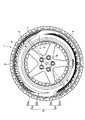
図1は、本実施形態における空気入りタイヤ1を示す図である。 FIG. 1 is a view showing a pneumatic tire 1 in the present embodiment.
空気入りタイヤ1は、トレッド部2と、サイドウォール部3とを有し、リム4に固定されている。 The pneumatic tire 1 has a tread portion 2 and a sidewall portion 3 and is fixed to a rim 4.
トレッド部2は、路面と接触する厚いゴム層であり、摩耗や外傷を防ぐための空気入りタイヤ1の外皮である。 The tread portion 2 is a thick rubber layer that comes into contact with the road surface, and is a skin of the pneumatic tire 1 for preventing wear and trauma.
サイドウォール部3は、一対備えられており、トレッド部2の両端から延びる壁面である。 A pair of sidewall portions 3 is provided, and is a wall surface extending from both ends of the tread portion 2.
また、サイドウォール部3は、タイヤ径方向に延びてタイヤ周方向に繰り返し形成されている複数のリッジ7と、所定の模様6とを有し、所定のタイヤ径方向幅を有してタイヤ周方向に延びる円弧環状帯5を有している。
Further, the sidewall portion 3 has a plurality of
リッジ7については、後に詳述する。
The
また、所定の模様6とは、空気入りタイヤ1のブランド名やサイズである。 The predetermined pattern 6 is the brand name or size of the pneumatic tire 1.
また、円弧環状帯5は、タイヤ周方向上において、偶数個の環状帯5a及び5bに分断されている。
Moreover, the circular arc zone 5 is divided into an even number of
この環状帯5a及び5bのタイヤ周方向長さは、円弧環状帯5を分断した数によってタイヤ全体のタイヤ周方向長さを除した数値の50〜100%である。
The circumferential lengths of the
例えば、空気入りタイヤ1の周方向長さが2000mmであり、同図に示すように、円弧環状帯5が2分割されている場合においては、2000mmを2で除した1000mmの50〜100%、即ち、500〜1000mmが、環状帯5a及び5bのタイヤ周方向長さとなる。
For example, in the case where the circumferential length of the pneumatic tire 1 is 2000 mm and the circular arc belt 5 is divided into two as shown in the figure, 50 to 100% of 1000 mm obtained by dividing 2000 mm by 2, That is, 500 to 1000 mm is the tire circumferential direction length of the
また、この環状帯5a及び5bは、タイヤ周方向に延びるリブ8と、リブ8よりタイヤ径方向外側に位置する外側層50a及び50dと、リブ8よりタイヤ径方向内側に位置する内側層50b及び50cとを有している。
The
この外側層50a及び50dと内側層50b及び50cのタイヤ径方向幅は、環状帯5a及び5bのタイヤ径方向幅の50±10%である。
The tire radial width of the
リブ8、外側層50a及び50d、内側層50b及び50cについては、後に詳述する。
The
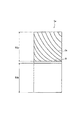
図2は、本実施形態における環状帯5a及び5bを示す図である。
FIG. 2 is a diagram showing the
なお、同図は、図1におけるAの領域を拡大した図である。 In addition, the same figure is the figure which expanded the area | region of A in FIG.
同図に示すように、一方の環状帯5a(以下において、第1環状帯5a)の外側層50aに形成されているリッジ7の傾斜方向は、タイヤの回転中心10を介して向かい合う他方の環状帯5b(以下において、第2環状帯5b)の内側層50cに形成されているリッジ7の傾斜方向と同一である。このため、同図に示すように、第1環状帯5aの外側層50aと第2環状帯5bの内側層50cとにB方向から光が当たることにより、双方において、C方向に光を反射させる。
As shown in the figure, the inclination direction of the
また、このリッジ7は、直線である。
The
リブ8は、タイヤ幅方向最大幅領域を含む位置に形成されており、タイヤ径方向幅が0.3〜3mmであり、高さが0.2〜1.5mmである。
The
ここで、タイヤ最大幅領域とは、空気入りタイヤにおけるサイドウォール部3において、タイヤ幅方向に最も突出している領域である。 Here, the tire maximum width region is a region that protrudes most in the tire width direction in the sidewall portion 3 of the pneumatic tire.
なお、環状帯5a及び5bに形成されているリッジ7の傾斜方向が、同図とは逆であってもよい。
The inclination direction of the
図3は、本実施形態における円弧環状帯5を示す断面図である。なお、同図は、図2における第1環状帯5aの断面Dを示している。
FIG. 3 is a cross-sectional view showing the circular arc zone 5 in the present embodiment. The figure shows a cross section D of the first
同図に示すように、リッジ7は、略三角形の形状を有し、トレッド幅方向に突出している。リッジ7は、タイヤ径方向(同図において、奥行き方向)に対して所定の角度傾斜してタイヤ周方向に繰り返し形成されている。
As shown in the figure, the
リブ8は、同図に示すように、タイヤ周方向に延びている。
As shown in the figure, the
なお、リッジ7は、同図に示すような略三角形状であることに限定されず、半円形状等の形状を有するものであってもよい。
The
(変更例1)
以下において、本実施形態におけるリッジ7の変更例について、図4を用いて説明する。
(Modification 1)
Hereinafter, a modified example of the
図4は、本実施形態における第1環状帯5aの変更例を示す図である。
FIG. 4 is a diagram showing a modification of the first
なお、図4は、上述した図2における第1環状帯5aの変更例である。
FIG. 4 is a modification of the first
同図に示すように、リッジ7aは、曲線である。 As shown in the figure, the ridge 7a is a curve.
なお、リッジ7aは、同図における方向とは逆の向きに湾曲していてもよい。 Note that the ridge 7a may be curved in a direction opposite to the direction in FIG.
[実施形態2]
以下において、本実施形態における空気入りタイヤ1について説明する。
[Embodiment 2]
Below, the pneumatic tire 1 in this embodiment is demonstrated.
なお、本実施形態における空気入りタイヤ1は、第1実施形態における空気入りタイヤ1と第1環状帯5a及び第2環状帯5bが異なるのみであるため、異なる部分についてのみ説明し、重複する部分については,説明を省略する。
In addition, since the pneumatic tire 1 in the present embodiment is different from the pneumatic tire 1 in the first embodiment only in the first
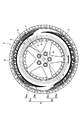
図5は、本実施形態における空気入りタイヤ1を示す図である。 FIG. 5 is a view showing the pneumatic tire 1 in the present embodiment.
同図に示すように、第1環状帯5aの外側層50a及び内側層50bと、第2環状帯5bの内側層50c及び外側層50dとには、リッジ7が形成されている。
As shown in the figure, a
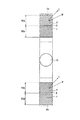
図6は、本実施形態における第1環状帯5a及び第2環状帯5bを示す図である。
FIG. 6 is a diagram showing the first
同図に示すように、環状帯5a及び5bの外側層50a及び50dと内側層50b及び50cとに形成されているリッジ7の傾斜方向は、異なる。
As shown in the figure, the inclination directions of the
(変更例1)
以下において、本実施形態におけるリッジ7の変更例について、図7を用いて説明する。
(Modification 1)
Hereinafter, a modified example of the
図7は、本実施形態における環状帯5a及び5bの変更例を示す図である。
FIG. 7 is a diagram showing a modification of the
同図に示すように、リッジ7は、曲線である。
As shown in the figure, the
なお、リッジ7は、同図における方向とは逆の向きに湾曲していてもよい。
The
(本実施形態における空気入りタイヤの作用・効果)
本実施形態に係る空気入りタイヤ1によると、円弧環状帯5が、タイヤ周方向上において、偶数個の環状帯5a及び5bに分断されており、環状帯5a及び5bが、タイヤ周方向に延びるリブ8と、リブ8よりタイヤ径方向外側に位置する外側層50a及び50dと、リブ8よりタイヤ径方向内側に位置する内側層50b及び50cとを有し、一方の環状帯(第1環状帯5a)の外側層50aに形成されているリッジ7の傾斜方向が、タイヤの回転中心10を介して向かい合う他方の環状帯(第2環状帯5b)の内側層50cに形成されているリッジ7の傾斜方向と同一であるため、タイヤが車輌に装着されている場合における上部と下部とに形成されている環状帯5a及び5bにおいて、それぞれの環状帯5a及び5bの上方と下方とに当たる光を同一方向に反射させることができ、上部と下部との双方の視認性を向上することができる。
(Operation / Effect of Pneumatic Tire in this Embodiment)
According to the pneumatic tire 1 according to the present embodiment, the circular arc zone 5 is divided into an even number of
また、タイヤ径方向に延びてタイヤ周方向に繰り返し形成されている複数のリッジ7が円弧環状帯5に形成されているため、該リッジ7が縞模様となり、縞模様の錯覚効果によって円弧環状帯5を狭く見せることにより、扁平率の低いタイヤに見せることができる。
In addition, since the plurality of
また、リブ8が、タイヤ幅方向最大幅領域を含む位置に形成されているため、一方から光が当たる場合に、この光の当たり方が異なる外側層50a及び50dと内側層50b及び50cとを分断することができる。また、所定の模様6を有する円弧環状帯5にこのリブ8が形成されていることにより、所定の模様6をより目立たせることができる。
Further, since the
また、外側層50a及び50dと内側層50b及び50cのタイヤ径方向幅が、環状帯5a及び5bのタイヤ径方向幅の50±10%であるため、外側層50a及び50dと内側層50b及び50cとのタイヤ径方向幅を略同一にすることができることにより、外側層50a及び50dと内側層50b及び50cとの双方の視認性を向上することができる。
Further, since the tire radial width of the
また、環状帯5a及び5bの外側層50a及び50dと内側層50b及び50cとに形成されているリッジ7の傾斜方向が、異なるため、一方から当たる光を異なる方向へ反射させることにより、視認性を確保しながら光の反射方向をより複雑にし、円弧環状帯5をよりよく見せることができる。
Further, since the inclination directions of the
また、一方の環状帯(第1環状帯5a)の外側層50aに形成されているリッジ7の傾斜方向が、タイヤの回転中心10を介して向かい合う他方の環状帯(第2環状帯5b)の内側層50cに形成されているリッジ7の傾斜方向と同一であり、環状帯5a及び5bの外側層50a及び50dと内側層50b及び50cとに形成されているリッジ7の傾斜方向が異なるため、周上においてリッジ7の傾斜方向が変化する位置が現われるが、円弧環状帯5が、タイヤ周方向上において、偶数個の環状帯5a及び5bに分断されているため、周上の任意の位置においてリッジ7の傾斜方向を容易に変化させることができる。
Further, the inclination direction of the
また、リブ8は、タイヤ径方向幅が0.3〜3mmであり、高さが0.2〜1.5mmであることが好ましい。リブ8のタイヤ径方向幅が0.3mmより小さいと、モールドによってリッジ7を加工する際に、加工誤差により、外側層50a及び50dと内側層50b及び50cとが重なってしまう恐れがあり、3mmより大きいと、外側層50a及び50dと内側層50b及び50cとが離れすぎてしまうため、2本の層で1つの円弧環状帯5であるという一体感を失ってしまう。また、リブ8の高さは構造上リッジ7の高さよりも高くなるが、リブ8の高さが0.2mmよりも小さいと、リッジ7も0.2mmより小さくなってしまい、リッジ7の効果が不十分となり、1.5mmより大きいと、リブ8がリッジ7よりも目立ってしまうだけではなく、モールドの加工効率、及びサイドウォール部3における耐久性が低下する。
The
また、リッジ7は、直線又は曲線であることが好ましい。リッジ7の形状を直線と曲線とで使い分けることにより、また、曲線の角度を変えることにより、反射の方向等を変えることができ、視認性を確保しながら円弧環状帯5の見え方を変えることができる。
The
また、環状帯5a及び5bのタイヤ周方向長さが、円弧環状帯5を分断した数によってタイヤ全体の周方向長さを除した数値の50〜100%であるため、環状帯5a及び5bにおいて、所定の模様6を形成する領域を充分に確保することができ、該所定の模様6を見易く表示することができる。
Moreover, since the tire circumferential direction length of the
1…空気入りタイヤ
2…トレッド部
3…サイドウォール部
4…リム
5…円弧環状帯
5a…第1環状帯
5b…第2環状帯
6…模様
7…リッジ
7a…リッジ
8…リブ
10…回転中心
50a、50d…外側層
50b、50c…内側層
DESCRIPTION OF SYMBOLS 1 ... Pneumatic tire 2 ... Tread part 3 ... Side wall part 4 ... Rim 5 ... Arc
Claims (7)
前記円弧環状帯は、タイヤ周方向上において、偶数個の環状帯に分断されており、
前記環状帯は、タイヤ周方向に延びるリブと、前記リブよりタイヤ径方向外側に位置する外側層と、前記リブよりタイヤ径方向内側に位置する内側層とを有し、
一方の環状帯の前記外側層に形成されている前記リッジの傾斜方向は、タイヤの回転中心を介して向かい合う他方の環状帯の前記内側層に形成されているリッジの傾斜方向と同一であることを特徴とする空気入りタイヤ。 A plurality of ridges extending in the tire radial direction and repeatedly formed in the tire circumferential direction, and having a predetermined pattern, an arc annular band extending in the tire circumferential direction with a predetermined tire radial width, In the pneumatic tire in the part,
The circular arc zone is divided into an even number of annular zones on the tire circumferential direction,
The annular belt has a rib extending in the tire circumferential direction, an outer layer positioned on the outer side in the tire radial direction from the rib, and an inner layer positioned on the inner side in the tire radial direction from the rib,
The inclination direction of the ridge formed in the outer layer of one annular band is the same as the inclination direction of the ridge formed in the inner layer of the other annular band facing through the rotation center of the tire. Pneumatic tire characterized by.
The tire circumferential direction length of the annular band is 50 to 100% of a numerical value obtained by dividing the tire circumferential direction length of the entire tire by the number of divided circular arc bands. Pneumatic tire.
Priority Applications (1)
| Application Number | Priority Date | Filing Date | Title |
|---|---|---|---|
| JP2005106835A JP4673113B2 (en) | 2005-04-01 | 2005-04-01 | Pneumatic tire |
Applications Claiming Priority (1)
| Application Number | Priority Date | Filing Date | Title |
|---|---|---|---|
| JP2005106835A JP4673113B2 (en) | 2005-04-01 | 2005-04-01 | Pneumatic tire |
Publications (2)
| Publication Number | Publication Date |
|---|---|
| JP2006282079A true JP2006282079A (en) | 2006-10-19 |
| JP4673113B2 JP4673113B2 (en) | 2011-04-20 |
Family
ID=37404413
Family Applications (1)
| Application Number | Title | Priority Date | Filing Date |
|---|---|---|---|
| JP2005106835A Expired - Fee Related JP4673113B2 (en) | 2005-04-01 | 2005-04-01 | Pneumatic tire |
Country Status (1)
| Country | Link |
|---|---|
| JP (1) | JP4673113B2 (en) |
Cited By (11)
| Publication number | Priority date | Publication date | Assignee | Title |
|---|---|---|---|---|
| JP2011105231A (en) * | 2009-11-19 | 2011-06-02 | Bridgestone Corp | Pneumatic tire |
| JP2011116306A (en) * | 2009-12-07 | 2011-06-16 | Bridgestone Corp | Tire |
| JP2011126335A (en) * | 2009-12-15 | 2011-06-30 | Bridgestone Corp | Tire |
| JP2011148338A (en) * | 2010-01-19 | 2011-08-04 | Bridgestone Corp | Tire |
| JP2012076649A (en) * | 2010-10-04 | 2012-04-19 | Bridgestone Corp | Tire |
| JP2012148651A (en) * | 2011-01-18 | 2012-08-09 | Yokohama Rubber Co Ltd:The | Pneumatic tire |
| JP2013237292A (en) * | 2012-05-11 | 2013-11-28 | Bridgestone Corp | Pneumatic tire, assembly of tire and rim wheel, and method for decorating tire side part |
| JP2014058319A (en) * | 2014-01-06 | 2014-04-03 | Bridgestone Corp | Pneumatic tire |
| US9365080B2 (en) | 2009-11-19 | 2016-06-14 | Bridgestone Corporation | Tire |
| JP6210127B1 (en) * | 2016-05-26 | 2017-10-11 | 横浜ゴム株式会社 | Pneumatic tire |
| WO2018155441A1 (en) * | 2017-02-21 | 2018-08-30 | 横浜ゴム株式会社 | Pneumatic tire |
Citations (2)
| Publication number | Priority date | Publication date | Assignee | Title |
|---|---|---|---|---|
| JPH07164831A (en) * | 1993-12-10 | 1995-06-27 | Bridgestone Corp | Pneumatic tire having strip-shaped design |
| JP2003252011A (en) * | 2002-02-26 | 2003-09-09 | Sumitomo Rubber Ind Ltd | Tire |
-
2005
- 2005-04-01 JP JP2005106835A patent/JP4673113B2/en not_active Expired - Fee Related
Patent Citations (2)
| Publication number | Priority date | Publication date | Assignee | Title |
|---|---|---|---|---|
| JPH07164831A (en) * | 1993-12-10 | 1995-06-27 | Bridgestone Corp | Pneumatic tire having strip-shaped design |
| JP2003252011A (en) * | 2002-02-26 | 2003-09-09 | Sumitomo Rubber Ind Ltd | Tire |
Cited By (14)
| Publication number | Priority date | Publication date | Assignee | Title |
|---|---|---|---|---|
| US9365080B2 (en) | 2009-11-19 | 2016-06-14 | Bridgestone Corporation | Tire |
| JP2011105231A (en) * | 2009-11-19 | 2011-06-02 | Bridgestone Corp | Pneumatic tire |
| JP2011116306A (en) * | 2009-12-07 | 2011-06-16 | Bridgestone Corp | Tire |
| JP2011126335A (en) * | 2009-12-15 | 2011-06-30 | Bridgestone Corp | Tire |
| JP2011148338A (en) * | 2010-01-19 | 2011-08-04 | Bridgestone Corp | Tire |
| JP2012076649A (en) * | 2010-10-04 | 2012-04-19 | Bridgestone Corp | Tire |
| JP2012148651A (en) * | 2011-01-18 | 2012-08-09 | Yokohama Rubber Co Ltd:The | Pneumatic tire |
| JP2013237292A (en) * | 2012-05-11 | 2013-11-28 | Bridgestone Corp | Pneumatic tire, assembly of tire and rim wheel, and method for decorating tire side part |
| JP2014058319A (en) * | 2014-01-06 | 2014-04-03 | Bridgestone Corp | Pneumatic tire |
| JP6210127B1 (en) * | 2016-05-26 | 2017-10-11 | 横浜ゴム株式会社 | Pneumatic tire |
| WO2017204308A1 (en) * | 2016-05-26 | 2017-11-30 | 横浜ゴム株式会社 | Pneumatic tire |
| JP2017210132A (en) * | 2016-05-26 | 2017-11-30 | 横浜ゴム株式会社 | Pneumatic tire |
| WO2018155441A1 (en) * | 2017-02-21 | 2018-08-30 | 横浜ゴム株式会社 | Pneumatic tire |
| JPWO2018155441A1 (en) * | 2017-02-21 | 2019-11-07 | 横浜ゴム株式会社 | Pneumatic tire |
Also Published As
| Publication number | Publication date |
|---|---|
| JP4673113B2 (en) | 2011-04-20 |
Similar Documents
| Publication | Publication Date | Title |
|---|---|---|
| JP4673113B2 (en) | Pneumatic tire | |
| JP6574770B2 (en) | Tire with a specific texture on the sidewall | |
| JP5310805B2 (en) | Pneumatic tire | |
| CN102848861B (en) | Pneumatic tire | |
| JP5793159B2 (en) | Pneumatic tire | |
| JPH11291722A (en) | Pneumatic tire provided with annular ornamental unit formed by many ridges | |
| CN103009936B (en) | Pneumatic tire | |
| JP6972966B2 (en) | tire | |
| JP2015033983A (en) | Pneumatic tire | |
| JP3946850B2 (en) | Pneumatic tire with an annular decorative body consisting of many ridges | |
| JP2009067355A (en) | Tire | |
| JP2012148651A (en) | Pneumatic tire | |
| JP2015013605A (en) | Pneumatic tire | |
| JP4502437B2 (en) | Pneumatic tire | |
| WO2012029239A1 (en) | Pneumatic tire | |
| WO2015029928A1 (en) | Pneumatic tire | |
| JP2019196152A (en) | Pneumatic tire | |
| JPH08318717A (en) | Pneumatic tire provided with decoration body consisting of multiple ridge | |
| JP2003146025A (en) | Tire | |
| JPH0939518A (en) | Pneumatic tire provided with ornamental body of numbers of ridges | |
| JP4315515B2 (en) | Pneumatic tire | |
| JP2010052585A (en) | Pneumatic tire | |
| JP3326428B1 (en) | tire | |
| CN107709051A (en) | Tire | |
| JP3645358B2 (en) | Pneumatic tire with a decorative body consisting of many ridges |
Legal Events
| Date | Code | Title | Description |
|---|---|---|---|
| A621 | Written request for application examination |
Free format text: JAPANESE INTERMEDIATE CODE: A621 Effective date: 20080327 |
|
| A977 | Report on retrieval |
Free format text: JAPANESE INTERMEDIATE CODE: A971007 Effective date: 20101028 |
|
| A131 | Notification of reasons for refusal |
Free format text: JAPANESE INTERMEDIATE CODE: A131 Effective date: 20101102 |
|
| A521 | Written amendment |
Free format text: JAPANESE INTERMEDIATE CODE: A523 Effective date: 20101221 |
|
| TRDD | Decision of grant or rejection written | ||
| A01 | Written decision to grant a patent or to grant a registration (utility model) |
Free format text: JAPANESE INTERMEDIATE CODE: A01 Effective date: 20110118 |
|
| A01 | Written decision to grant a patent or to grant a registration (utility model) |
Free format text: JAPANESE INTERMEDIATE CODE: A01 |
|
| A61 | First payment of annual fees (during grant procedure) |
Free format text: JAPANESE INTERMEDIATE CODE: A61 Effective date: 20110120 |
|
| R150 | Certificate of patent or registration of utility model |
Ref document number: 4673113 Country of ref document: JP Free format text: JAPANESE INTERMEDIATE CODE: R150 Free format text: JAPANESE INTERMEDIATE CODE: R150 |
|
| FPAY | Renewal fee payment (event date is renewal date of database) |
Free format text: PAYMENT UNTIL: 20140128 Year of fee payment: 3 |
|
| R250 | Receipt of annual fees |
Free format text: JAPANESE INTERMEDIATE CODE: R250 |
|
| R250 | Receipt of annual fees |
Free format text: JAPANESE INTERMEDIATE CODE: R250 |
|
| R250 | Receipt of annual fees |
Free format text: JAPANESE INTERMEDIATE CODE: R250 |
|
| R250 | Receipt of annual fees |
Free format text: JAPANESE INTERMEDIATE CODE: R250 |
|
| R250 | Receipt of annual fees |
Free format text: JAPANESE INTERMEDIATE CODE: R250 |
|
| R250 | Receipt of annual fees |
Free format text: JAPANESE INTERMEDIATE CODE: R250 |
|
| LAPS | Cancellation because of no payment of annual fees |