JP2006276700A - Recording paper carrying speed detecting method, recording paper carrying speed control method and image forming apparatus - Google Patents
Recording paper carrying speed detecting method, recording paper carrying speed control method and image forming apparatus Download PDFInfo
- Publication number
- JP2006276700A JP2006276700A JP2005098557A JP2005098557A JP2006276700A JP 2006276700 A JP2006276700 A JP 2006276700A JP 2005098557 A JP2005098557 A JP 2005098557A JP 2005098557 A JP2005098557 A JP 2005098557A JP 2006276700 A JP2006276700 A JP 2006276700A
- Authority
- JP
- Japan
- Prior art keywords
- recording paper
- conveyance speed
- transfer
- image forming
- forming apparatus
- Prior art date
- Legal status (The legal status is an assumption and is not a legal conclusion. Google has not performed a legal analysis and makes no representation as to the accuracy of the status listed.)
- Withdrawn
Links
Images


Abstract
Description
本発明は、電子写真方式・静電記録方式・磁気記録方式等の作像プロセス機構により記録紙に目的の画像情報に対応した未定着画像を形成担持させ、この記録紙を定着器に導入して記録紙上の未定着画像を熱定着させて画像記録物として出力させる、レーザープリンタ、複写機、ファクシミリ等の画像形成装置に関し、特にその記録紙搬送速度検出方法、記録紙搬送速度制御方法に関する。 In the present invention, an unfixed image corresponding to target image information is formed and supported on a recording paper by an image forming process mechanism such as an electrophotographic system, an electrostatic recording system, or a magnetic recording system, and the recording paper is introduced into a fixing device. In particular, the present invention relates to an image forming apparatus such as a laser printer, a copying machine, and a facsimile machine that heat-fixes an unfixed image on a recording sheet and outputs it as an image recording material, and more particularly to a recording sheet conveyance speed detection method and a recording sheet conveyance speed control method.
従来、熱ローラ方式やフィルム加熱方式の定着装置においては、加熱体と加圧部材との圧接ニップ部に記録紙を侵入させ両部材により記録紙を挟持搬送させて記録紙を加熱処理する。例えば、フィルム加熱方式の定着装置では、加熱体にフィルムを介して圧接させる加圧部材(例えば、加圧ローラ)を駆動回転させることで、フィルムを加熱体に摺動移動させつつ、フィルムもしくはフィルムと記録紙を一緒に加熱体と加圧ローラとの圧接ニップ部において挟持搬送させる構成が採用されている。 2. Description of the Related Art Conventionally, in a heat roller type or film heating type fixing device, a recording sheet is inserted into a pressure nip portion between a heating body and a pressure member, and the recording sheet is nipped and conveyed by both members, and the recording sheet is heated. For example, in a film heating type fixing device, a film or film is slid and moved to a heating body by driving and rotating a pressure member (for example, a pressure roller) that presses the heating body through the film. And the recording paper are held and conveyed together at the pressure nip portion between the heating body and the pressure roller.
このような定着装置においては、構成部品の温度状態によって記録紙の挟持搬送速度に変動を生じる。すなわち、加圧部材駆動式の定着装置では、装置の稼動に伴って、加圧ローラの温度が上昇することで、加圧ローラは熱により微妙ながら膨張しその外径が大きくなる。加圧ローラは通常一定回転数で回転駆動されているため、加圧ローラが高温のときは低温のときよりも熱膨張が大きくなって回転周速度が増加し、記録紙の挟持搬送速度が速くなってしまう。その結果、加圧ローラの温度状態によって定着装置による記録紙の挟持搬送速度に速度差が生じる。 In such a fixing device, the recording paper nipping / conveying speed varies depending on the temperature state of the components. That is, in the fixing member driving type fixing device, the temperature of the pressure roller rises with the operation of the device, so that the pressure roller is slightly expanded due to heat and its outer diameter is increased. Since the pressure roller is normally driven to rotate at a constant rotational speed, when the pressure roller is hot, the thermal expansion becomes larger and the rotational peripheral speed increases than when the pressure roller is low, and the nipping and conveying speed of the recording paper increases. turn into. As a result, a speed difference occurs in the nipping and conveying speed of the recording paper by the fixing device depending on the temperature state of the pressure roller.
このような要因により、例えば、この加熱装置を画像加熱定着装置として画像形成装置に使用した場合、定着装置よりも上流側の処理部である作像部、例えば画像転写部での記録紙の搬送速度は所定の値に一定に保たれているため、記録紙が転写部から定着装置のニップ部に到達して挟持搬送状態になると、加圧ローラが高温状態時には転写部での記録紙搬送速度よりも定着装置のニップ部における記録紙の搬送速度が大きい状態を生じる。その結果として、記録紙が定着装置の記録紙搬送速度で引っ張られて搬送されるので、記録画像が記録紙搬送方向に引き伸ばされてしまい、いわゆる画像伸びが生じてしまう。場合によっては、その画像伸びで画像後端部が記録紙後端から外れて欠損してしまうことになる。
上記問題を解決するために、加圧ローラの温度を測定して、その膨張量を予測して駆動速度を変化させる方法も提案されている(特許文献1、2)。しかし、この方法では誤差が大きい為、より正確な制御ができない。
In order to solve the above problem, a method of changing the driving speed by measuring the temperature of the pressure roller and predicting the expansion amount is proposed (
また、フィルムに複数の反射部を設け、反射型センサのON/OFFの周期を読み取ることによってフィルムの周速を検知し、その周速が一定になるように逐次、加圧ローラの駆動速度を変化させる方法が提案されている(特許文献3)。この方法では、フィルムに複数の反射板を設けなくてはならないため、コストが高くなる。また、それらの反射板の間隔を均等にしなければならないため精度良く加工するのが難しい。 Also, the film is provided with a plurality of reflecting portions, and the peripheral speed of the film is detected by reading the ON / OFF cycle of the reflective sensor, and the driving speed of the pressure roller is sequentially adjusted so that the peripheral speed is constant. A method of changing is proposed (Patent Document 3). In this method, since a plurality of reflecting plates must be provided on the film, the cost increases. In addition, it is difficult to process with high accuracy because the interval between the reflectors must be uniform.
さらに、記録紙検知部材(以下TOPセンサ)の記録紙先端検知から記録紙後端検知までの時間と記録紙サイズとに基づいて記録紙搬送速度を算出し加圧ローラ等の駆動速度を変化させる方法が提案されている(特許文献4)。この方法では、TOPセンサが記録紙により摩耗するとTOPセンサのレスポンス速度が変化し(タイミングが早くなり)、経年的に正確な速度検知ができなくなってしまう。 Further, the recording paper conveyance speed is calculated based on the time from the recording paper leading edge detection to the recording paper trailing edge detection and the recording paper size of the recording paper detection member (hereinafter referred to as TOP sensor), and the driving speed of the pressure roller or the like is changed. A method has been proposed (Patent Document 4). In this method, when the TOP sensor is worn by the recording paper, the response speed of the TOP sensor changes (timing is advanced), and accurate speed detection becomes impossible over time.
本発明はこのような背景においてなされたものであり、その目的は、反射板等の部材追加によるコストアップ、TOPセンサ等の部材劣化による検知精度低下等の不具合を招くことなく、画像伸びを低減し印刷倍率精度を向上させることのできる記録紙搬送速度検出方法、記録紙搬送速度制御方法および画像形成装置を提供することにある。 The present invention has been made in such a background, and the object thereof is to reduce image expansion without incurring problems such as cost increase due to addition of a member such as a reflector and a decrease in detection accuracy due to deterioration of a member such as a TOP sensor. Another object of the present invention is to provide a recording paper conveyance speed detection method, a recording paper conveyance speed control method, and an image forming apparatus capable of improving the printing magnification accuracy.
本発明では、未定着のトナー像を転写部材により記録紙に転写し、定着させる画像形成装置において、転写ニップ部に記録紙が存在する時と存在しない時とで転写部材に印加される電圧または電流が変化することに着目して、その電流もしくは電圧変化タイミングをモニタすることにより記録紙先端から記録紙後端までの時間を検知しその検知結果と通紙記録紙サイズに基づいて記録紙搬送速度を求める。 In the present invention, in an image forming apparatus in which an unfixed toner image is transferred to a recording paper by a transfer member and fixed, the voltage applied to the transfer member when the recording paper is present or not at the transfer nip portion, or Paying attention to the current change, the current or voltage change timing is monitored to detect the time from the leading edge of the recording paper to the trailing edge of the recording paper, and the recording paper is transported based on the detection result and the passing paper size. Find the speed.
すなわち、本発明による記録紙搬送速度検出方法は、未定着のトナー像を転写部材により記録紙に転写し、定着させる画像形成装置における記録紙搬送速度検出方法であって、転写部材に印加されている電流もしくは電圧の変化タイミングを検出するステップと、前記変化タイミングに基づいて、記録紙先端から記録紙後端までが前記転写部材を通過するに要する時間を求めるステップと、求められた時間と当該記録紙サイズとに基づいて記録紙の搬送速度を算出するステップとを備えたことを特徴とする。 In other words, the recording paper conveyance speed detection method according to the present invention is a recording paper conveyance speed detection method in an image forming apparatus for transferring an unfixed toner image onto a recording paper by a transfer member and fixing it. Detecting a change timing of a current or a voltage, a step of obtaining a time required for the recording paper leading end to pass through the transfer member based on the change timing, And a step of calculating a recording paper conveyance speed based on the recording paper size.
また本発明による記録紙搬送速度制御方法は、上記求められた記録紙搬送速度に従って記録紙搬送速度を制御する。 The recording paper transport speed control method according to the present invention controls the recording paper transport speed in accordance with the obtained recording paper transport speed.
本発明による画像形成装置は、未定着のトナー像を転写部材により記録紙に転写し、定着させる画像形成装置であって、転写部材に印加されている電流もしくは電圧の変化タイミングを検出する検出手段と、前記変化タイミングに基づいて、記録紙先端から記録紙後端までが前記転写部材を通過するに要する時間を求める手段と、求められた時間と当該記録紙サイズとに基づいて記録紙の搬送速度を算出する手段と、算出された搬送速度を目的の搬送速度に合わせるように搬送速度を変更する搬送速度変更手段とを備えたことを特徴とする。 An image forming apparatus according to the present invention is an image forming apparatus that transfers an unfixed toner image onto a recording sheet by a transfer member and fixes the toner image, and detects a change timing of a current or voltage applied to the transfer member. And a means for obtaining a time required for the recording paper from the leading edge to the trailing edge of the recording paper to pass through the transfer member based on the change timing, and the conveyance of the recording paper based on the obtained time and the recording paper size. The apparatus includes a means for calculating the speed and a transport speed changing means for changing the transport speed so that the calculated transport speed matches the target transport speed.
このようにして、画像形成装置において、常に目標とする記録紙搬送速度を維持することにより画像伸びを最小限にし印刷倍率精度が向上する。 In this way, in the image forming apparatus, by always maintaining the target recording paper conveyance speed, the image expansion is minimized and the printing magnification accuracy is improved.
前記搬送速度変更手段は、例えば、定着ユニットの記録紙搬送速度を変更することにより搬送速度を変更することができる。 The transport speed changing unit can change the transport speed by changing the recording paper transport speed of the fixing unit, for example.
前記搬送速度変更手段による搬送速度の変更は、記録紙搬送速度を算出したプリントの次のプリントとの間で行うことができる。これによりページ単位に記録紙搬送速度を調整することができる。 The change of the conveyance speed by the conveyance speed changing unit can be performed between the prints subsequent to the print for which the recording paper conveyance speed is calculated. This makes it possible to adjust the recording paper conveyance speed for each page.
本発明によれば、未定着のトナー像を転写部材により記録紙に転写し、定着させる画像形成装置において、従来のように反射板等の部材追加によるコストアップ、TOPセンサ等の部材劣化による検知精度低下を招くことなく、画像伸びを最小限にし印刷倍率精度を向上させることができる。 According to the present invention, in an image forming apparatus in which an unfixed toner image is transferred onto a recording sheet by a transfer member and fixed, the cost increases due to the addition of a member such as a reflection plate as in the past, and the detection due to deterioration of a member such as a TOP sensor The image magnification can be minimized and the printing magnification accuracy can be improved without causing a decrease in accuracy.
以下、本発明の好適な実施の形態について図面を参照しながら詳細に説明する。 DESCRIPTION OF EXEMPLARY EMBODIMENTS Hereinafter, preferred embodiments of the invention will be described in detail with reference to the drawings.
図1は本発明が適用される画像形成装置1の概略側面図である。プロセスカートリッジ2は画像形成装置1に着脱可能に収納される。画像形成装置1としてここではプリンタを例に説明するが、複写機やファクシミリであってもよい。
FIG. 1 is a schematic side view of an
画像形成プロセスは、パソコン等の外部装置(図示せず)からプリンタインタフェースやLANを介して画像データを受信して開始される。具体的には、まず、帯電ローラ3により像担持体4を所定の一定電位に帯電させてから露光部(図示せず)にて画像を形成する像担持体(例えば感光ドラム)4上のポイントを露光させ所定の電位に低下させる。複写機の場合には、画像読取部(図示せず)により原稿から読み取った画像に基づいて露光を行う。ファクシミリの場合には画像読取装置5の代わりに通信回線からファクシミリデータを受信するデータ受信部を備え、受信データにより得られた画像に基づいて露光を行う。
The image forming process is started by receiving image data from an external device (not shown) such as a personal computer via a printer interface or a LAN. Specifically, first, a point on the image carrier (for example, a photosensitive drum) 4 on which an image is formed by an exposure unit (not shown) after the image carrier 4 is charged to a predetermined constant potential by the charging roller 3. Is exposed to a predetermined potential. In the case of a copying machine, exposure is performed based on an image read from an original by an image reading unit (not shown). In the case of a facsimile, a data receiving unit that receives facsimile data from a communication line is provided instead of the
このように露光により低下させた像担持体4上の電位と現像スリーブ6に印加する電位との差、つまり電界の作用を利用して、現像スリーブ6上の帯電されているトナー7を、駆動部21により回転駆動される像担持体4上へ付着させる。像担持体4に付着したトナー7は、像担持体4の回転により所定の転写領域に搬送され、転写ローラ8の作用によって、記録紙カセット13から給紙ローラ14により搬送されてきた記録紙Pに転写される。
The charged toner 7 on the developing sleeve 6 is driven by utilizing the difference between the potential on the image carrier 4 and the potential applied to the developing sleeve 6 that has been lowered by exposure, that is, the action of the electric field. The image is adhered onto the image carrier 4 that is rotationally driven by the
トナー像が転写された記録紙Pは、定着ユニット10まで搬送され、定着フィルム11と加圧ローラ12のニップ部において、熱と加圧によりトナー像が記録紙P上に定着され、排紙ローラ16により排紙される。加圧ローラ12は駆動部22により回転駆動される。駆動部22の回転速度は本発明における搬送速度変更手段を構成するCPU23により可変制御される。
The recording paper P onto which the toner image has been transferred is conveyed to the fixing unit 10, and the toner image is fixed on the recording paper P by heat and pressure at the nip portion between the fixing film 11 and the pressure roller 12. 16 is discharged. The pressure roller 12 is rotationally driven by the
像担持体4上に付着し転写しきれなかったトナー7は、クリーニングブレード9によりプロセスカートリッジ2内の廃トナー収容スペースに掻き落され回収される。記録紙検知部材としてのTOPセンサ15の役割としては、記録紙Pの先端がTOPセンサ15の位置にきてTOPセンサ15を倒すと、そのタイミングが基点となり画像プロセス形成開始に関係する高圧、露光のタイミングが決定する。記録紙Pの後端がTOPセンサ15の位置を抜けるとTOPセンサ15は起上がり、そのタイミングが基点となり画像形成終了に関係する高圧、露光のタイミングが決定される。
The toner 7 that adheres to the image carrier 4 and cannot be transferred is scraped off and collected by the cleaning blade 9 into the waste toner storage space in the
プリント中の転写高圧制御には定電圧制御と定電流制御とがあるが、まず定電圧制御について説明する。 The transfer high voltage control during printing includes constant voltage control and constant current control. First, constant voltage control will be described.
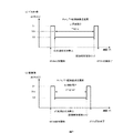
図2(a)は記録紙Pが像担持体4と転写ローラ8のニップ部に到達していない時の様子を示す図であり、図2(b)は記録紙Pが像担持体4と転写ローラ8のニップ部を通過中の様子を示す図である。
FIG. 2A is a diagram illustrating a state where the recording paper P has not reached the nip portion between the image carrier 4 and the
図2(a)、図2(b)において転写高圧電源17により転写ローラ8に定電圧Vtrが印加され、その時流れる電流i1により記録紙Pの背面を帯電させ像担持体4と記録紙Pの背面電位との電位差により像担持体4上のトナー7を記録紙Pの印刷面に転写させる。本実施の形態では、転写高圧電源17と転写ローラ8との間に転写電流検知用負荷18を設ける。転写電流検知用負荷18の抵抗値Rは転写ローラ8の抵抗値より小さくする。例えば、転写ローラの抵抗値は10の9乗Ωであり、転写電流検知用負荷18の抵抗値Rは10の6乗Ωとする。このように転写ローラの抵抗値に比べ転写電流検知用負荷18の抵抗値は1000分の1とかなり小さく、転写プロセスに関してなんら影響は与えない。
2A and 2B, a constant voltage Vtr is applied to the
図2(a)の記録紙Pが像担持体4と転写ローラ8のニップ部に到達していない時に転写高圧が出力する電圧がVtrで、その時流れる電流がi1であるとすると、転写電流検知用負荷18での電圧降下V1はV1=i1*Rである。
Assuming that the voltage output by the transfer high voltage is Vtr when the recording paper P in FIG. 2A has not reached the nip portion between the image carrier 4 and the
同様に図2(b)の記録紙Pが像担持体4と転写ローラ8のニップ部を通過中においては定電圧制御である為、印加している電圧はVtrであり、記録紙Pがニップ部中に存在する為、記録紙Pの抵抗値分だけ流れる電流が低下する。その時の電流値をi2(i1>i2)とすると、転写電流検知用負荷18の抵抗値Rでの電圧降下V2はV2=i2*Rとなる。
Similarly, since the constant voltage control is performed while the recording paper P in FIG. 2B passes through the nip portion between the image carrier 4 and the
例えば、転写電流検知用負荷18の抵抗値RをR=10の6乗Ω、転写に必要な電流値i2が3.5μA、その時の転写ローラ8の抵抗値で3.5μAを出力する為の印加電圧Vtr=2.0kVとする。また、印加電圧Vtr=2.0kVかつ記録紙Pがニップ部にない時の電流値i1が5.0μAとする。このような条件下で、記録紙Pがニップ部に存在しない場合と存在する場合の転写電流検知用負荷18での電圧降下V1,V2はそれぞれ次のようになる。
(1)記録紙Pがニップ部に存在しない時:V1=[5.0](μA)*[10の6乗](Ω)
=[5.0](V)
(2)記録紙Pがニップ部に存在する時:V2=[3.5]( μA)*[10の6乗](Ω)
=[3.5](V)
For example, the resistance value R of the transfer
(1) When the recording paper P is not present in the nip portion: V1 = [5.0] (μA) * [10 to the sixth power] (Ω)
= [5.0] (V)
(2) When the recording paper P is present in the nip portion: V2 = [3.5] (μA) * [10 to the sixth power] (Ω)
= [3.5] (V)
このような電圧V1からV2への変動は記録紙Pの先端がニップ部に突入した時に発生し、逆に電圧V2からV1への変動は記録紙Pの後端がニップ部を抜けた時に発生する。この転写電流検知用負荷18での電圧出力変動をモニタすることにより、記録紙Pのニップ部への先端の突入時点および後端の抜け時点を検知し、その間の時間と、ユーザ設定により決定された記録紙サイズに基づいてその時の記録紙搬送速度を算出することができる。
Such a change from the voltage V1 to V2 occurs when the leading edge of the recording paper P enters the nip portion. Conversely, a fluctuation from the voltage V2 to V1 occurs when the trailing edge of the recording paper P leaves the nip portion. To do. By monitoring the voltage output fluctuation at the transfer
図3は転写電流検知用負荷18の降下電圧変動に基づく記録紙の先端および後端の検知および記録紙Pの搬送速度算出の方法を説明するための図である。図3(a)はデフォルト状態つまり加圧ローラが熱膨張していない時の電圧出力波形を示し、図3(b)は加圧ローラが熱膨張し記録紙Pの搬送速度が速くなってしまった時の電圧出力波形を示している。
FIG. 3 is a diagram for explaining a method of detecting the leading and trailing edges of the recording paper and calculating the conveyance speed of the recording paper P based on the voltage drop variation of the transfer
最初にTOPセンサ15が記録紙先端を検知すると、記録紙先端が転写ニップ部より上流側に位置する時点t0で転写高圧Vtrが印加される。その時の転写電流検知用負荷18の電圧降下はV1である。次に時点t1で記録紙Pの先端が転写ニップ部に突入すると、転写電流検知用負荷18での電圧降下はV2となる。さらに、時点t2で、記録紙Pの後端が転写ニップ部を抜けると転写電流検知用負荷18での電圧降下はV1となる。その後、時点t3で転写高圧Vtrの印加が終了する。
First, when the
あらかじめ閾値電圧Vthを設定しておき転写電圧Vtr印加期間(t0〜t3)内に転写電流検知用負荷18での出力値viが閾値電圧Vth以下になった時のタイミングt1と閾値電圧Vth以上になったときのタイミングt2をCPUによりメモリに格納する。記録紙Pが転写ニップ部を通過するのに要した時間Tは、T=t2−t1で求めらる。この時間Tと記録紙サイズLに基づいて、記録紙搬送速度Pvが次式で求められる。
・記録紙搬送速度Pv=L/T
The threshold voltage Vth is set in advance, and the output value vi at the transfer
・ Recording paper conveyance speed Pv = L / T
これに対して、加圧ローラ膨張時はその周速度が速くなるため、図3(b)に示すように、図3(a)の時点t2、t3にそれぞれ対応する時点t2’、t3’のタイミングが早くなる。このときの記録紙搬送速度Pv’は、記録紙Pが転写ニップ部を通過するのに要した時間T’=t2’−t1’と記録紙サイズLに基づいて、上記と同様にして次式で求められる。
・記録紙搬送速度Pv’=L/T’
On the other hand, when the pressure roller is expanded, the peripheral speed is increased. Therefore, as shown in FIG. 3B, at the time points t2 ′ and t3 ′ corresponding to the time points t2 and t3 in FIG. The timing is early. The recording paper conveyance speed Pv ′ at this time is expressed by the following equation based on the time T ′ = t2′−t1 ′ required for the recording paper P to pass through the transfer nip and the recording paper size L in the same manner as described above. Is required.
Recording paper transport speed Pv ′ = L / T ′
例えばA4サイズ(搬送方向サイズ:297mm)を連続通紙した時、V1=5.0V、 V2=3.5V、 Vth=4.25V で初期の記録紙Pが転写ニップ部を通過するのに要した時間Tが3.324sec、加圧ローラ膨張時(連続200枚後)のT’が3.308secであったとすると、初期時および加圧ローラ膨張時(200枚連続通紙後)の記録紙搬送速度Pv、Pv’はそれぞれ下記のようになる。
・初期の記録紙搬送速度Pv=297(mm)/3.324(sec)
=89.3501(mm/sec)
・200枚連続通紙後記録紙搬送速度Pv’=297(mm)/3.308(sec)
=89.7823(mm/sec)
For example, when A4 size (conveying direction size: 297 mm) is continuously passed, V1 = 5.0V, V2 = 3.5V, Vth = 4.25V, and it is necessary for the initial recording paper P to pass through the transfer nip. Assuming that the time T is 3.324 sec and T ′ when the pressure roller is expanded (after 200 consecutive sheets) is 3.308 sec, the recording paper at the initial time and when the pressure roller is expanded (after 200 consecutive sheets are passed) The conveyance speeds Pv and Pv ′ are as follows.
-Initial recording paper conveyance speed Pv = 297 (mm) /3.324 (sec)
= 89.3501 (mm / sec)
・ Recording paper transport speed Pv '= 297 (mm) /3.308 (sec) after continuous 200 sheets
= 89.7823 (mm / sec)
よって膨張時には記録紙搬送速度が0.4322mm/sec速くなっていることが分かる。この結果に基づいて、加圧ローラ12の速度をデフォルト時から0.4322mm/secだけ低下させれば、加圧ローラ12の膨張の影響を相殺することができる。 Therefore, it can be seen that the recording paper conveyance speed is 0.4322 mm / sec faster during expansion. Based on this result, if the speed of the pressure roller 12 is reduced by 0.4322 mm / sec from the default, the influence of expansion of the pressure roller 12 can be offset.
図4は、本実施の形態における制御の手順を表したフローチャートである。この制御の手順を表すプログラムは図示しないROM(メモリ)内に格納され、CPUがこれを解釈実行することにより、この制御が実現される。 FIG. 4 is a flowchart showing a control procedure in the present embodiment. A program representing the control procedure is stored in a ROM (memory) (not shown), and this control is realized by the CPU interpreting and executing it.
まず、n枚の連続プリント指示が入力されると、プリント枚数カウント変数xを1にセットし(S11)、前回転中にATVC(Active Transfer Voltage Control)検知を行い現在の転写ローラ8の抵抗値で目標の電流値を流す為に要する電圧Vtrを決定する(S12)。そこで、x枚目のプリントがスタートする(S13)。このx枚目のプリントにおいて、TOPセンサ15が記録紙先端を検知すると、記録紙先端が転写ニップ部より上流側の位置で転写高圧Vtrが印加開始される(S14)。記録紙後端が転写ニップ部を抜けた後に転写高圧Vtrの印加が終了する(S15)。x枚目のプリントが終了したら(S16)、カウント変数xをインクリメント(+1)する(S17)。xがn+1に達したらプリント動作を終了する。xがn+1に達するまでは、ステップS13へ戻って次のページのプリントを続行する。
First, when an instruction for continuous printing of n sheets is input, the print sheet count variable x is set to 1 (S11), ATVC (Active Transfer Voltage Control) detection is performed during the previous rotation, and the current resistance value of the
転写電流検知用負荷18でのVi検知は転写高圧Vtr印加中に行われる(S21)。一方で、閾値レベルVthが決定される(S31)。記録紙の種類によりその抵抗は変わりうるので、閾値レベルVthは記録紙の種類によって変更することができる。電圧Viが検知されたら、図3で説明したように、閾値レベルVthと電圧Viとの関係に基づいて、記録紙先端の転写ニップ部への突入時点t1および記録紙後端の転写ニップ部抜け時点t2を検出する(S32)。さらに、この時点t1、t2および使用している記録紙サイズ(L)情報に基づいて、記録紙搬送速度Pvを算出する(S33)。この算出された記録紙搬送速度Pvとデフォルトの基準搬送速度PVrefとに基づいて、記録紙搬送速度変化分を算出する(S34)。この算出結果に基づいて、その変化分だけ加圧ローラ12の速度を変更指示する(S35)。この加圧ローラ12の速度の変更は、検知したプリントと次のプリントとの紙間中に行う。もし次のプリントが存在しないのであれば可変せずにそのままプリント動作を終了させる。
Vi detection by the transfer
以上説明した実施の形態では、プリント中転写高圧制御は定電圧制御の場合を説明した。しかし、定電流制御であってもよい。以下、プリント中転写高圧制御を定電流制御により行う場合について説明する。ここでは図5の転写高圧電源19が定電流制御となる。図5(a)は転写ニップ部への記録紙Pの通過前、図5(b)は記録紙Pの通過中を示している。転写高圧電源19は定電流制御である為記録紙Pが転写ニップ部での存在有無に関わらず常に同じ電流を流している。ここではi1を常時流しているとする。転写高圧電源19が印加している電圧Vtrは記録紙Pが転写ニップ部での存在有無により変化する。記録紙Pが転写ニップ部に存在する時には記録紙Pの抵抗値分だけ電圧Vtrより高い電圧Vtr’となる。本実施の形態では上記と同じ方法でこのVtrの電圧出力変動を、閾値Vthに照らしてモニタすることにより、記録紙Pの転写ニップ部への先端突入時点および後端抜け時点を検知し、その先端から後端までの通過時間とユーザ設定により決定された記録紙サイズに基づいてその時の記録紙搬送速度を算出し、搬送速度変化分を導きだす。そしてその変化分だけ加圧ローラの速度を可変する。 In the embodiment described above, the case where the high voltage control during printing is the constant voltage control has been described. However, constant current control may be used. Hereinafter, a case where the high voltage control during printing is performed by constant current control will be described. Here, the transfer high-voltage power supply 19 of FIG. 5 performs constant current control. FIG. 5A shows a state before the recording paper P passes through the transfer nip portion, and FIG. Since the transfer high-voltage power supply 19 uses constant current control, the recording paper P always flows the same current regardless of the presence or absence of the recording paper P in the transfer nip portion. Here, it is assumed that i1 is constantly flowing. The voltage Vtr applied by the transfer high-voltage power supply 19 varies depending on whether or not the recording paper P exists in the transfer nip portion. When the recording paper P exists in the transfer nip portion, the voltage Vtr ′ is higher than the voltage Vtr by the resistance value of the recording paper P. In the present embodiment, the voltage output fluctuation of Vtr is monitored against the threshold value Vth by the same method as described above to detect the time when the leading edge of the recording paper P enters the transfer nip and the time when the trailing edge slips out. Based on the passing time from the leading edge to the trailing edge and the recording paper size determined by the user setting, the recording paper conveyance speed at that time is calculated, and the change in the conveyance speed is derived. Then, the speed of the pressure roller is varied by the change.
以上、本発明の好適な実施の形態について詳細に説明したが、上記で言及した以外にも種々の変形、変更を行うことができる。例えば、上記実施の形態では、記録紙のサイズに基づく寸法値をメモリに格納して用いた。しかし、使用する記録紙によっては寸法にばらつきがありうる。そこで、朝一番や長時間スタンバイ後の加圧ローラがあまり膨張していないときに画像形成を行った場合、その記録紙の転写部への先端突入時点および後端抜け時点を検知し、その先端から後端までの通過時間を現在のカセット内の記録紙の基準値としてメモリに格納し、その後の記録紙通過時間をその基準値に合わせるようにしてもよい。 The preferred embodiment of the present invention has been described in detail above, but various modifications and changes other than those mentioned above can be made. For example, in the above embodiment, a dimension value based on the size of the recording paper is stored in the memory and used. However, the size may vary depending on the recording paper used. Therefore, when image formation is performed when the pressure roller after the first standby in the morning or for a long time has not expanded much, the time when the leading edge of the recording paper enters the transfer section and the time when the trailing edge slips out is detected. It is also possible to store the passage time from the rear end to the rear end in the memory as the reference value of the recording paper in the current cassette, and adjust the subsequent recording paper passage time to the reference value.
1…画像形成装置、2…プロセスカートリッジ、3…帯電ローラ、4…像担持体(感光ドラム)、5…レーザスキャナユニット、6…現像スリーブ、7…トナー、8…転写ローラ、9…クリーニングブレード 10…定着ユニット、11…定着フィルム、12…加圧ローラ、13…記録紙カセット、14…給紙ローラ、15…記録紙検知部材(TOPセンサ)、16…排紙ローラ、17…転写高圧電源(定電圧制御)、18…転写電流検知用負荷、P…記録紙、19…転写高圧電源(定電流制御)、23…CPU
DESCRIPTION OF
Claims (5)
転写部材に印加されている電流もしくは電圧の変化タイミングを検出するステップと、
前記変化タイミングに基づいて、記録紙先端から記録紙後端までが前記転写部材を通過するに要する時間を求めるステップと、
求められた時間と当該記録紙サイズとに基づいて記録紙の搬送速度を算出するステップと
を備えたことを特徴とする記録紙搬送速度検出方法。 A method for detecting a conveyance speed of a recording paper in an image forming apparatus in which an unfixed toner image is transferred onto a recording paper by a transfer member and fixed.
Detecting a change timing of a current or voltage applied to the transfer member;
Based on the change timing, obtaining a time required for the recording paper leading edge to the recording paper trailing edge to pass through the transfer member;
And a step of calculating a recording paper conveyance speed based on the obtained time and the recording paper size.
転写部材に印加されている電流もしくは電圧の変化タイミングを検出するステップと、
前記変化タイミングに基づいて、記録紙先端から記録紙後端までが前記転写部材を通過するに要する時間を求めるステップと、
求められた時間と当該記録紙サイズとに基づいて記録紙の搬送速度を算出するステップと、
算出された搬送速度を目的の搬送速度に合わせるように搬送速度を補正するステップと
を備えたことを特徴とする記録紙搬送速度制御方法。 A recording paper conveyance speed control method in an image forming apparatus for transferring and fixing an unfixed toner image onto a recording paper by a transfer member,
Detecting a change timing of a current or voltage applied to the transfer member;
Based on the change timing, obtaining a time required for the recording paper leading edge to the recording paper trailing edge to pass through the transfer member;
Calculating a recording paper conveyance speed based on the obtained time and the recording paper size;
And a step of correcting the transport speed so that the calculated transport speed matches the target transport speed.
転写部材に印加されている電流もしくは電圧の変化タイミングを検出する検出手段と、
前記変化タイミングに基づいて、記録紙先端から記録紙後端までが前記転写部材を通過するに要する時間を求める手段と、
求められた時間と当該記録紙サイズとに基づいて記録紙の搬送速度を算出する手段と、
算出された搬送速度を目的の搬送速度に合わせるように搬送速度を変更する搬送速度変更手段と
を備えたことを特徴とする画像形成装置。 An image forming apparatus for transferring and fixing an unfixed toner image onto a recording sheet by a transfer member,
Detection means for detecting a change timing of the current or voltage applied to the transfer member;
Means for obtaining a time required for the recording paper from the leading edge of the recording paper to the trailing edge of the recording paper to pass through the transfer member based on the change timing;
Means for calculating the conveyance speed of the recording paper based on the obtained time and the recording paper size;
An image forming apparatus comprising: a conveyance speed changing unit configured to change the conveyance speed so that the calculated conveyance speed matches a target conveyance speed.
Priority Applications (1)
| Application Number | Priority Date | Filing Date | Title |
|---|---|---|---|
| JP2005098557A JP2006276700A (en) | 2005-03-30 | 2005-03-30 | Recording paper carrying speed detecting method, recording paper carrying speed control method and image forming apparatus |
Applications Claiming Priority (1)
| Application Number | Priority Date | Filing Date | Title |
|---|---|---|---|
| JP2005098557A JP2006276700A (en) | 2005-03-30 | 2005-03-30 | Recording paper carrying speed detecting method, recording paper carrying speed control method and image forming apparatus |
Publications (2)
| Publication Number | Publication Date |
|---|---|
| JP2006276700A true JP2006276700A (en) | 2006-10-12 |
| JP2006276700A5 JP2006276700A5 (en) | 2008-05-15 |
Family
ID=37211500
Family Applications (1)
| Application Number | Title | Priority Date | Filing Date |
|---|---|---|---|
| JP2005098557A Withdrawn JP2006276700A (en) | 2005-03-30 | 2005-03-30 | Recording paper carrying speed detecting method, recording paper carrying speed control method and image forming apparatus |
Country Status (1)
| Country | Link |
|---|---|
| JP (1) | JP2006276700A (en) |
Cited By (2)
| Publication number | Priority date | Publication date | Assignee | Title |
|---|---|---|---|---|
| JP2008250250A (en) * | 2007-03-30 | 2008-10-16 | Canon Finetech Inc | Heating device and image forming apparatus having the same |
| JP2017223731A (en) * | 2016-06-13 | 2017-12-21 | 株式会社リコー | Fixing device and image forming apparatus |
-
2005
- 2005-03-30 JP JP2005098557A patent/JP2006276700A/en not_active Withdrawn
Cited By (2)
| Publication number | Priority date | Publication date | Assignee | Title |
|---|---|---|---|---|
| JP2008250250A (en) * | 2007-03-30 | 2008-10-16 | Canon Finetech Inc | Heating device and image forming apparatus having the same |
| JP2017223731A (en) * | 2016-06-13 | 2017-12-21 | 株式会社リコー | Fixing device and image forming apparatus |
Similar Documents
| Publication | Publication Date | Title |
|---|---|---|
| US8027607B2 (en) | Image forming apparatus | |
| JP2002287560A (en) | Image forming apparatus | |
| JP5110806B2 (en) | Image forming apparatus | |
| JP4598970B2 (en) | Image forming apparatus | |
| JPH10186946A (en) | Image forming device | |
| JP4372691B2 (en) | Fixing apparatus and image forming apparatus having the same | |
| JP4594013B2 (en) | Image forming apparatus | |
| JP4047193B2 (en) | Image forming apparatus | |
| JP6907682B2 (en) | Image formation system and control method of image formation system | |
| JP2006276700A (en) | Recording paper carrying speed detecting method, recording paper carrying speed control method and image forming apparatus | |
| JP5516143B2 (en) | Image forming apparatus | |
| JP2006171480A (en) | Image forming apparatus | |
| JP2004178888A (en) | Heating device | |
| JPH1020718A (en) | Image forming device | |
| JP4701051B2 (en) | Fixing apparatus and image forming apparatus | |
| US20240126198A1 (en) | Image forming apparatus | |
| JP2000075693A (en) | Image forming device | |
| JP2003316229A (en) | Image forming apparatus, recording medium carrying speed control method, program, and storage medium | |
| JP2005266505A (en) | Image forming apparatus | |
| JP2006038920A (en) | Image forming apparatus | |
| JP2001242730A (en) | Image forming device | |
| JP2009075411A (en) | Image forming apparatus | |
| JPH1184782A (en) | Image forming device | |
| JP2024057199A (en) | Image forming device | |
| JP2006154645A (en) | Image forming apparatus |
Legal Events
| Date | Code | Title | Description |
|---|---|---|---|
| A521 | Written amendment |
Free format text: JAPANESE INTERMEDIATE CODE: A523 Effective date: 20080331 |
|
| A621 | Written request for application examination |
Free format text: JAPANESE INTERMEDIATE CODE: A621 Effective date: 20080331 |
|
| A761 | Written withdrawal of application |
Free format text: JAPANESE INTERMEDIATE CODE: A761 Effective date: 20100126 |