JP2006265993A - Pipe installation method for stabilizing ground, prelining method for tunnel and excavation device used therefor - Google Patents
Pipe installation method for stabilizing ground, prelining method for tunnel and excavation device used therefor Download PDFInfo
- Publication number
- JP2006265993A JP2006265993A JP2005088159A JP2005088159A JP2006265993A JP 2006265993 A JP2006265993 A JP 2006265993A JP 2005088159 A JP2005088159 A JP 2005088159A JP 2005088159 A JP2005088159 A JP 2005088159A JP 2006265993 A JP2006265993 A JP 2006265993A
- Authority
- JP
- Japan
- Prior art keywords
- drilling
- bit
- inner pipe
- pipe
- hole
- Prior art date
- Legal status (The legal status is an assumption and is not a legal conclusion. Google has not performed a legal analysis and makes no representation as to the accuracy of the status listed.)
- Pending
Links
Images


Abstract
Description
本発明は、地盤の安定化用管体設置工法、トンネルの先受け工法及びそれに用いる掘削装置に関するものである。 The present invention relates to a tube installation method for stabilizing ground, a tunnel tip receiving method, and an excavation apparatus used therefor.
地中構造物、たとえばトンネルを構築する場合、地盤、とりわけ地山を安定化させるために、地中構造物を構築するに先立って、その上方に管体を設置または建込む先受け工法が汎用されている。この管体はこれ自体で、あるいはその管体を注入材の注入通路としさらに補強することで、地盤の安定化に寄与するものである。 When constructing underground structures, such as tunnels, a pre-construction method that installs or builds a tube above the underground structure is generally used prior to constructing the underground structure in order to stabilize the ground, especially ground. Has been. This tubular body contributes to the stabilization of the ground by itself or by further reinforcing the tubular body as an injection passage for the injection material.
近年の大断面のトンネルの指向に伴って先受け工法の必要性がより高まっている。先受け工法には、坑口から施工を開始するパイプルーフ工法やフォアパイリング工法などがあるが、削孔長が短い故に施工能率が高くない問題がある。長尺の管体の設置のためには、目的の掘削線に沿った孔曲りのない削孔が必要である。そこで、本発明者らは、削孔過程の途中で孔曲りを確実に修正でき、もって長尺の削孔が可能である地盤の安定化用管体設置工法、トンネルの先受け工法及び孔曲り修正機能を有する掘削装置を提案している(特許文献1参照)。
しかしながら、上記発明ではトップハンマー方式(ロータリーパーカッション方式)の削孔駆動装置を主として用い、かつ内管の基端側に打撃力を与え、それを内管ビットに伝達させるかたちとなっているので、削孔深度が深くなっていくと、先端のビットに打撃力が伝達し難くなるため、削孔速度が減速して削孔効率が悪化するという問題があった。
したがって、本発明の主たる課題は、削孔深度が深くなっても削孔速度が減速せず、削孔効率が優れた地盤の安定化用管体設置工法、トンネルの先受け工法及びそれに用いる掘削装置を提供することにある。
However, in the above invention, a top hammer type (rotary percussion type) drilling drive device is mainly used, and a striking force is applied to the proximal end side of the inner pipe, which is transmitted to the inner pipe bit. As the drilling depth becomes deeper, it becomes difficult to transmit the striking force to the bit at the tip, so that the drilling speed is reduced and the drilling efficiency is deteriorated.
Therefore, the main problem of the present invention is that the drilling speed does not slow down even when the drilling depth is deep and the ground stabilization pipe installation method with excellent drilling efficiency, the tunnel tip receiving method, and the excavation used therefor To provide an apparatus.
上記課題を解決した本発明は次記のとおりである。
<請求項1記載の発明>
請求項1記載の発明は、外管と、内管と、この内管の先端側に取付けられたダウンザホールハンマーと、このダウンザホールハンマーの先端に取付けられ、このダウンザホールハンマーによる打撃力のみを与えて削孔を行うと、地盤が有する削孔反力との関係で削孔方向が偏心させる力を生じさせる形状の内管ビットと、を備えた掘削装置を用いて地盤の安定化用の管体を地盤内に設置する工法であって、直線削孔の時には、前記内管ビットに軸心回りの回転力、及び前記ダウンザホールハンマーによる打撃力を与えつつ削孔を行い、削孔に伴う孔曲りの修正時には、前記内管ビットによる打撃力のみで削孔を行い、上記の削孔を目標長まで削孔した後、前記外管は地盤中に残置させて地盤の安定化用の管体とすることを特徴とする地盤の安定化用管体設置工法である。
The present invention that has solved the above problems is as follows.
<Invention of
According to the first aspect of the present invention, an outer tube, an inner tube, a down-the-hole hammer attached to the tip side of the inner tube, and a tip attached to the tip-end of the down-the-hole hammer, the cutting force is applied only by the down-the-hole hammer. When the hole is drilled, the pipe for stabilizing the ground is formed using an excavator having an inner pipe bit having a shape that generates a force that decenters the drilling direction in relation to the drilling reaction force of the ground. It is a construction method that is installed in the ground, and in the case of straight drilling, drilling is performed while giving the inner pipe bit a rotational force around the axis and a striking force by the down-the-hole hammer. At the time of correction, drilling is performed only with the striking force of the inner pipe bit, and after drilling the above-mentioned drilling hole to a target length, the outer pipe is left in the ground to form a pipe for stabilizing the ground. The ground is characterized by A reduction for tube installation method.
<請求項2記載の発明>
請求項2記載の発明は、前記内管ビットは、該内管の軸心方向に対して傾斜した受圧面を有するテーパー状である、請求項1記載の地盤の安定化用管体設置工法である。
<Invention of
According to a second aspect of the present invention, the inner pipe bit has a tapered shape having a pressure receiving surface inclined with respect to the axial center direction of the inner pipe. is there.
<請求項3記載の発明>
請求項3記載の発明は、前記外管の先端に、外管ビットが取付けられ、該外管ビットは、前記内管ビットと略同一の傾斜角の受圧面を有するテーパー状であり、かつ、内管ビットと係合することによって、内管ビットの回転により同方向に回転する構成であり、直線削孔の時には、内管ビットと外管ビットの受圧面の傾斜が揃った状態で、内管ビット及び外管ビットが回転すると共に、内管ビットで打撃力を与えて削孔を行い、削孔に伴う孔曲りの修正時には、前記内管ビットによる打撃力のみで削孔を行う、請求項2記載の地盤の安定化用管体設置工法である。
<Invention of
According to a third aspect of the present invention, an outer pipe bit is attached to the tip of the outer pipe, and the outer pipe bit has a taper shape having a pressure receiving surface with substantially the same inclination angle as the inner pipe bit, and By engaging with the inner tube bit, the inner tube bit rotates in the same direction as the inner tube bit rotates. The pipe bit and the outer pipe bit rotate, and the inner pipe bit applies a striking force to perform drilling, and when correcting the bending of the hole due to the drilling, the inner pipe bit performs drilling only with the striking force.
(請求項1乃至3記載の発明の作用効果)
内管ビットとして、打撃力のみを与えて削孔を行うと、地盤が有する削孔反力との関係で削孔方向がある方向に偏心させる力を生じさせる形状のものを使用する。たとえば、内管ビットを該内管の軸心方向に対して傾斜した受圧面を有するテーパー状にすると、ダウンザホールハンマーによる打撃力によりビット(そして管体の先端部も)はテーパーの受圧面(傾斜面)の先端に向かう方向に逃げるようになる。本発明はこの原理を積極的に採用するものである。
すなわち、内管ビットに軸心回りの回転力、及びダウンザホールハンマーによる打撃力を与えつつ削孔を行うことで、この受圧面(傾斜面)の回転により逃げの力が相殺されるため、直線の削孔が保証される。それに対して、内管ビットによる打撃力のみで削孔を行うことによって、地盤が有する削孔反力(切削抵抗)との関係で削孔方向がテーパーの傾斜した受圧面の先端方向に偏心させる力を生じ、削孔に伴う孔曲りの修正が可能となるものである。
本発明に係る地盤の掘削装置では、内管の先端側に取付けられたダウンザホールハンマーにより内管ビットに打撃力を与えるため、打撃力の伝達ロスが少なく、削孔深度が深くなっても削孔速度が減速する虞はない。そのため、従来型の内管の基端側に打撃力を与えるトップハンマー方式(ロータリーパーカッション方式)に比べて、削孔効率が優れる。
また、外管の先端に、外管ビットを取付け、この外管ビットを内管ビットと略同一の傾斜角の受圧面を有するテーパー状とし、かつ、内管ビットと係合することによって、内管ビットの回転により同方向に回転する構成とすることにより、より削孔効率を向上させることができる。
(Effects of the Inventions of
As the inner pipe bit, when the hole is drilled by applying only the striking force, a shape that generates a force that decenters the hole in a certain direction due to the drilling reaction force of the ground is used. For example, if the inner pipe bit is tapered with a pressure receiving surface inclined with respect to the axial direction of the inner pipe, the bit (and the tip of the tube body) is also tapered by the impact force of the down-the-hole hammer (inclined). Escape in the direction toward the tip of the surface. The present invention actively adopts this principle.
That is, by performing drilling while giving the inner pipe bit a rotational force around the axis and a striking force by the down-the-hole hammer, the relief force is offset by the rotation of the pressure receiving surface (inclined surface). Drilling is guaranteed. On the other hand, by performing drilling only with the striking force of the inner pipe bit, the drilling direction is decentered toward the tip of the pressure-receiving surface with the taper inclined in relation to the drilling reaction force (cutting resistance) of the ground. A force is generated, and it becomes possible to correct the hole bending accompanying the drilling.
In the ground excavation apparatus according to the present invention, since the impact force is given to the inner pipe bit by the down-the-hole hammer attached to the distal end side of the inner pipe, there is little transmission loss of the impact force, and even if the drilling depth becomes deeper There is no risk of slowing down. Therefore, the drilling efficiency is superior to the top hammer method (rotary percussion method) in which the striking force is applied to the proximal end side of the conventional inner pipe.
An outer tube bit is attached to the tip of the outer tube, and the outer tube bit is tapered with a pressure-receiving surface having substantially the same inclination angle as the inner tube bit, and is engaged with the inner tube bit to By adopting a configuration in which the tube bit rotates in the same direction, the drilling efficiency can be further improved.
<請求項4記載の発明>
請求項4記載の発明は、外管と、内管と、この内管の先端側に取付けられたダウンザホールハンマーと、このダウンザホールハンマーの先端に取付けられ、このダウンザホールハンマーによる打撃力のみを与えて削孔を行うと、地盤が有する削孔反力との関係で削孔方向が偏心させる力を生じさせる形状の内管ビットと、を備えた掘削装置を用いて、トンネル横断面の上方に、トンネル掘削に先立ってトンネル線に沿って管体を建込む先受け工法であって、直線削孔の時には、前記内管ビットに軸心回りの回転力、及び前記ダウンザホールハンマーによる打撃力を与えつつ削孔を行い、削孔に伴う孔曲りの修正時には、前記内管ビットによる打撃力のみで削孔を行い、上記の削孔を目標長まで削孔した後、前記外管は地盤中に残置させて地盤の安定化用の管体とすることを特徴とするトンネルの先受け工法である。
<Invention of
The invention according to
<請求項5記載の発明>
請求項5記載の発明は、前記内管ビットは、該内管の軸心方向に対して傾斜した受圧面を有するテーパー状である、請求項4記載のトンネルの先受け工法である。
<Invention of Claim 5>
The invention according to claim 5 is the tunnel tip receiving method according to
<請求項6記載の発明>
請求項6記載の発明は、前記外管の先端に、外管ビットが取付けられ、該外管ビットは、前記内管ビットと略同一の傾斜角の受圧面を有するテーパー状であり、かつ、内管ビットと係合することによって、内管ビットの回転により同方向に回転する構成であり、直線削孔の時には、内管ビットと外管ビットの受圧面の傾斜が揃った状態で、内管ビット及び外管ビットが回転すると共に、内管ビットで打撃力を与えて削孔を行い、削孔に伴う孔曲りの修正時には、前記内管ビットによる打撃力のみで削孔を行う、請求項5記載のトンネルの先受け工法である。
<Invention of Claim 6>
According to a sixth aspect of the present invention, an outer tube bit is attached to the tip of the outer tube, and the outer tube bit has a tapered shape having a pressure receiving surface with substantially the same inclination angle as the inner tube bit, and By engaging with the inner tube bit, the inner tube bit rotates in the same direction as the inner tube bit rotates. The pipe bit and the outer pipe bit rotate, and the inner pipe bit applies a striking force to perform drilling, and when correcting the bending of the hole due to the drilling, the inner pipe bit performs drilling only with the striking force. Item 6. The tunnel receiving method according to Item 5.
(請求項4乃至6記載の発明の作用効果)
本発明は、トンネル横断面の上方に、トンネル掘削に先立ってトンネル線に沿って管体を建込む先受け工法において顕著な利点をもたらす。具体的に、従来、削孔精度の観点から15m程度、ある程度精度を無視したとしても50m程度であった削孔長を、100m以上及び施工機械を選定することで、300m以上の削孔が可能とすると共に、従来型の内管の基端側に打撃力を与えるトップハンマー方式(ロータリーパーカッション方式)に比べて、削孔速度が向上し、削孔効率が優れる。
(Effects of the Inventions of
The present invention provides significant advantages in a prior construction method in which a tube is built along the tunnel line prior to tunnel excavation above the tunnel cross section. Specifically, from the point of view of drilling accuracy, about 15m, even if the accuracy is neglected to some extent, by selecting a drilling length of 100m or more and construction machine, drilling of 300m or more is possible. In addition, the drilling speed is improved and the drilling efficiency is superior compared to the top hammer method (rotary percussion method) that applies a striking force to the proximal end side of the conventional inner pipe.
<請求項7記載の発明>
請求項7記載の発明は、外管と、内管と、この内管の先端側に取付けられたダウンザホールハンマーと、このダウンザホールハンマーの先端に取付けられ、このダウンザホールハンマーによる打撃力のみを与えて削孔を行うと、地盤が有する削孔反力との関係で削孔方向が偏心させる力を生じさせる形状の内管ビットと、を備えた掘削装置であって、直線削孔の時には、前記内管ビットに軸心回りの回転力、及び前記ダウンザホールハンマーによる打撃力を与えつつ削孔を行い、削孔に伴う孔曲りの修正時には、前記内管ビットによる打撃力のみで削孔を行う構成とされた、ことを特徴とする掘削装置である。
<Invention of Claim 7>
The invention according to claim 7 includes an outer tube, an inner tube, a down-the-hole hammer attached to the tip side of the inner tube, and a tip attached to the tip-end of the down-the-hole hammer. An excavator provided with an inner pipe bit having a shape that generates a force that decenters the drilling direction in relation to the drilling reaction force of the ground when the hole is drilled. A structure in which drilling is performed while applying a rotational force around the axis to the tube bit and a striking force by the down-the-hole hammer, and when correcting the bending of the hole due to the drilling, the drilling is performed only by the striking force by the inner tube bit The excavator is characterized by that.
<請求項8記載の発明>
請求項8記載の発明は、前記内管ビットは、該内管の軸心方向に対して傾斜した受圧面を有するテーパー状である、請求項7記載の掘削装置である。
<Invention of Claim 8>
The invention according to claim 8 is the excavator according to claim 7, wherein the inner pipe bit has a tapered shape having a pressure receiving surface inclined with respect to the axial direction of the inner pipe.
<請求項9記載の発明>
請求項9記載の発明は、前記外管の先端に、外管ビットが取付けられ、該外管ビットは、前記内管ビットと略同一の傾斜角の受圧面を有するテーパー状であり、かつ、内管ビットと係合することによって、内管ビットの回転により同方向に回転する構成であり、直線削孔の時には、内管ビットと外管ビットの受圧面の傾斜が揃った状態で、内管ビット及び外管ビットが回転すると共に、内管ビットで打撃力を与えて削孔を行い、削孔に伴う孔曲りの修正時には、前記内管ビットによる打撃力のみで削孔を行う、請求項8記載の掘削装置である。
<Invention of Claim 9>
According to the ninth aspect of the present invention, an outer tube bit is attached to the tip of the outer tube, and the outer tube bit has a tapered shape having a pressure-receiving surface having substantially the same inclination angle as the inner tube bit, and By engaging with the inner tube bit, the inner tube bit rotates in the same direction as the inner tube bit rotates. The pipe bit and the outer pipe bit rotate, and the inner pipe bit applies a striking force to perform drilling, and when correcting the bending of the hole due to the drilling, the inner pipe bit performs drilling only with the striking force. Item 9. The excavator according to Item 8.
(請求項7乃至9記載の発明の作用効果)
本発明の掘削装置は、前述の各工法に良好に利用できる。具体的には、内管ビットへの軸心回りの回転力、及びダウンザホールハンマーによる打撃力を選択・調整することにより、直進削孔と孔曲りの修正の態様を切り替えることができる。また、本発明に係る地盤の掘削装置では、内管の先端側に取付けられたダウンザホールハンマーにより内管ビットに打撃力を与えるため、打撃力の伝達ロスが少なく、削孔深度が深くなっても削孔速度が減速する虞はない。そのため、従来型の内管の基端側に打撃力を与えるトップハンマー方式(ロータリーパーカッション方式)に比べて、削孔効率が優れる。
また、外管の先端に、外管ビットを取付け、この外管ビットを内管ビットと略同一の傾斜角の受圧面を有するテーパー状とし、かつ、内管ビットと係合することによって、内管ビットの回転により同方向に回転する構成とすることにより、より削孔効率を向上させることができる。
(Effects of inventions of claims 7 to 9)
The excavator of the present invention can be used well for each of the above-described construction methods. Specifically, by selecting and adjusting the rotational force around the axis of the inner pipe bit and the striking force by the down-the-hole hammer, it is possible to switch between the straight-cutting hole and the correction mode of the hole bending. Further, in the ground excavation device according to the present invention, the impact force is given to the inner pipe bit by the down-the-hole hammer attached to the distal end side of the inner pipe, so that the transmission loss of the impact force is small and the drilling depth is deep. There is no risk that the drilling speed will slow down. Therefore, the drilling efficiency is superior to the top hammer method (rotary percussion method) in which the striking force is applied to the proximal end side of the conventional inner pipe.
An outer tube bit is attached to the tip of the outer tube, and the outer tube bit is tapered with a pressure-receiving surface having substantially the same inclination angle as the inner tube bit, and is engaged with the inner tube bit to By adopting a configuration in which the tube bit rotates in the same direction, the drilling efficiency can be further improved.
本発明によれば、削孔深度が深くなっても削孔速度が減速せず、削孔効率に優れる等の利点がもたらされる。 According to the present invention, even if the drilling depth is increased, the drilling speed is not reduced, and there are advantages such as excellent drilling efficiency.
以下、本発明の実施の形態を図面を参照しながらさらに詳説する。
(使用する管体と回転駆動装置との関係)
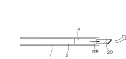
使用する管体は、図1及び図4に示すように、外管1と内管2とからなる二重管である。外管1は、内管2又はその先端側に取付けられたダウンザホールハンマー4に係合しており、それによって内管2に引張られながら削孔方向に進んでいく構成となっている。内管2の基端部は、回転駆動装置3に連結されて使用され、回転駆動装置3は、図1の場合には、ロータリーパーカッション方式によるもので、内管2の基端に対して回転力が与えられ、これが内管2の先端にも伝達されるものである。また、内管2の先端側にはダウンザホールハンマー4が取付けられており、内管2の先端に取付けられた内管ビット20に対して打撃力が伝達されるようになっている。削孔作業の際には、内管2の回転に伴って内管ビット20が回転すると共に、内管ビット20に対して打撃力が加えられるが、一方、外管1に対しては回転力や打撃力が伝えられることはない。
なお、内管2に軸心回りの回転力を与えることができ、かつ内管ビットに対して打撃力を与えることが可能な限り、適宜の回転駆動装置、及びダウンザホールハンマーを使用可能である。
Hereinafter, embodiments of the present invention will be described in more detail with reference to the drawings.
(Relationship between the tube used and the rotation drive device)
As shown in FIGS. 1 and 4, the tube used is a double tube made up of an
As long as a rotational force around the axis can be applied to the
また、管体は所定長さの単位管体を順次連結させながら、掘進を行うものである。さらに、以下の例においては、二重管の例を採って説明するが、その内管内に他の管体または流路を設けたり、外管との間に他の管体または流路を設けることが可能である。 Further, the pipe body is used for digging while sequentially connecting unit pipe bodies having a predetermined length. Furthermore, in the following example, an example of a double pipe will be described, but another pipe body or flow path is provided in the inner pipe, or another pipe body or flow path is provided between the outer pipe and the outer pipe. It is possible.
(削孔の基本概念)
本発明においては、図1に示すように、内管2の先端側にダウンザホールハンマー4を取付け、このダウンザホールハンマー4の先端に内管ビット20を設けている。ダウンザホールハンマー4は、ピストン(図示せず)とリーダー(図示せず)を備えており、地上から圧縮空気又は加圧した水を送ることによって、ピストンに上下運動をさせ、内管ビット20を打撃し掘削(穿孔)するものであり、ピストンの打撃エネルギーが直接内管ビット20に伝達されるため、伝達ロスが少なく、掘削対象地盤が硬岩等であっても効率よく削孔が可能である。
(Basic concept of drilling)
In the present invention, as shown in FIG. 1, a down-the-
内管ビット20は、ダウンザホール4による打撃力のみを与えて削孔を行うと、地盤が有する削孔反力との関係で削孔方向が偏心させる力を生じさせる形状であり、具体的には、内管2の軸心方向に対して傾斜した受圧面を有するテーパー形状である。この受圧面(傾斜面)が形成されていることにより、削孔の際には、内管2の回転及び打撃力によって直進をするが、打撃のみでは地盤が有する削孔反力(切削抵抗)との関係で削孔方向がテーパーの傾斜した受圧面の先端方向に偏心させる力を生じ、孔曲がりの修正がなされる。
The
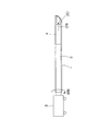
外管1の先端部は、図1に示すように、削孔方向に対して直交した面で構成されていてもよく、また、他の実施例として、図4に示すように、内管ビット20と同じようなテーパーの傾斜した受圧面で構成してもよい。
As shown in FIG. 1, the distal end portion of the
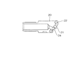
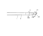
図3及び図6に示すように、内管ビット20に、ダウンザホールハンマー4により与えられる打撃力が作用すると、地盤が有する削孔反力(切削抵抗)を受けてビットは受圧面(傾斜面)の先端に向かう方向に逃げるようになるが、図2及び図5に示すように、削孔の際には、内管ビット20には、その基端から回転駆動装置3による回転力が作用するので、この受圧面(傾斜面)の回転により逃げの力が相殺されるため、直線の削孔が保証される。
As shown in FIGS. 3 and 6, when a striking force applied by the down-the-
他方、図3及び図6に示すように、削孔に伴う孔曲りの修正時には、修正方向に受圧面(傾斜面)の先端が向くように内管ビット20の位置を調整した状態で、回転駆動装置3による回転力を作用させないで、ダウンザホールハンマー4による打撃力のみを与えて削孔を行なう。なお、図6に示す外管1の先端を使用する場合には、その先端部を、内管ビット20の先端と同じ方向に傾斜面を向くように予め調整しておくことが好ましい。
On the other hand, as shown in FIG. 3 and FIG. 6, when correcting the bending of the hole due to drilling, the rotation is performed with the position of the
このように、ダウンザホールハンマー4による打撃で、この削孔方向の変更をある長さ続けることで、削孔方向の修正を行うことができる。そして、削孔方向の修正が終了したならば、再度前述の直線削孔を行う。
Thus, the drilling direction can be corrected by continuing the change in the drilling direction for a certain length by hitting with the down-the-
他の実施例として、図14及び図15に示すように、内管ビット20と略同一の傾斜角の受圧面を有するテーパー状の外管ビット10を、外管1の先端に設けたものを考えることができる。具体的には、この外管ビット10を内管ビット20の受圧面の傾斜と揃えて配置した状態で、外管ビット10を内管ビット20と係合させ、内管ビット20の回転により外管ビット10を同方向に回転させる構成を考えることができる。外管ビット10と内管ビット20との係合は、例えば、外管ビット10の内周面に突起部(図示せず)を設け、この突起部に嵌合するように内管ビット20に溝(図示せず)を削孔方向(軸方向)に延在するように形成しておき、外管ビット10の突起部と内管ビット20の溝との嵌合関係により、内管ビット20の回転に伴って外管ビット10が回転するが、内管ビット20の打撃については連動しない構成とすることができる。なお、外管1と外管ビット10を回り対偶の関係にして、外管ビット10を外管1に対して回転自在の構成にすれば、外管1を回転させずに外管ビット10のみを回転させることができる。
As another embodiment, as shown in FIGS. 14 and 15, a tapered
上記構成の場合、削孔の際では、図14に示すように、内管ビット20と外管ビット10とのそれぞれの受圧面の傾斜を揃えた状態で、内管2の回転によって内管ビット20及び外管ビット10が回転し、かつダウンザホールハンマー4により内管ビット20のみに打撃力が与えられる状態で直進削孔を行なう。一方、図15に示すように、ダウンザホールハンマー4による内管ビット20の打撃のみでは、地盤が有する削孔反力(切削抵抗)との関係で削孔方向がテーパーの傾斜した受圧面の先端方向に偏心させる力を生じ、孔曲がりの修正がなされるものである。なお、上記外管ビット10の突起部と内管ビット20の溝との嵌合関係を有する構成において、外管ビット10をロストビットとして、削孔作業終了の際に、外管1から切り離して孔内に残置させることもできる。
In the case of the above configuration, when drilling, as shown in FIG. 14, the inner tube bit is rotated by the rotation of the
本発明の掘削装置は、トンネルの先受け工法等を含む地盤の安定化用管体設置工法に良好に利用できる。具体的には、内管ビット20への軸心回りの回転力、及びダウンザホールハンマー4による打撃力を選択・調整することにより、直進削孔と孔曲りの修正の態様を切り替えることができる。また、本発明に係る地盤の掘削装置では、内管の先端側に取付けられたダウンザホールハンマー4により内管ビット20に打撃力を与えるため、打撃力の伝達ロスが少なく、削孔深度が深くなっても削孔速度が減速する虞はない。
The excavator of the present invention can be used well for a tube installation method for ground stabilization including a tunnel tip receiving method and the like. Specifically, by selecting and adjusting the rotational force around the axis of the
図13に示すように、従来型の内管の基端側に打撃力を与えるトップハンマー方式(ロータリーパーカッション方式)の掘削装置では、先端のビットに打撃力が伝達し難くなるため、削孔速度が減速して削孔効率が悪化していたが、本発明の掘削装置では、削孔深度が深くなっても削孔速度は一定である。そのため、従来型の掘削装置に比べて、削孔速度が削孔深度に比例して減速することがないため削孔効率が顕著に優れている。 As shown in FIG. 13, in a top hammer type (rotary percussion type) excavator that applies a striking force to the proximal end side of a conventional inner pipe, it is difficult to transmit the striking force to the bit at the tip. However, in the excavating apparatus of the present invention, the drilling speed is constant even when the drilling depth is increased. Therefore, the drilling efficiency is remarkably superior because the drilling speed does not decrease in proportion to the drilling depth as compared with the conventional excavator.
削孔の過程における適宜の時点で、外管1及び内管2の継ぎ足しを行う。この継ぎ足し自体は周知の事項であるので説明を省略する。
At an appropriate point in the drilling process, the
(内管ビット)
図7乃至図9を参照しながら、内管ビット20の構造を以下に説明する。
内管2の先端に螺合連結などにより一体化される内管ビット20は、有底筒状となり、内部は内管2を通して圧送される切削用水の通路となり、先端の吐出口24から吐出されるようになっている。内管ビット20の先端面の中央部分が重圧面(傾斜面)21とされている。先端面の適宜位置には多数のビット刃22が一体化されている。さらに、外周面には切削に伴う排泥溝25,25が形成されている。そして、内管ビット20の基端部分は、ダウンザホールハンマー4に連結されていると共に、外管1に内装される構成となっている。
(Inner pipe bit)
The structure of the
The
(回転角度の把握例)
削孔方向の修正を行うに際して、各時点での、特に内管ビット20角度把握は重要である。そこで、たとえば図10に示す形態を採れば、管体の継ぎ足し後においても把握できるようになる。すなわち、回転駆動装置3の回転ヘッド3Aにロータリーエンコーダなどの回転角検出器40を設けておく。なお、図10において、ダウンザホールハンマー4の図示は省略する。
(Example of grasping the rotation angle)
When correcting the drilling direction, it is particularly important to grasp the angle of the
当初または適宜の時点で、現在の内管ビット20の位置をセットしておく。図10の(a)の段階ではゼロリセット状態としてある。管体の1本分の削孔が終了したならば、(b)に示すように、外管チャッキング4Aにより外管1を把持し、回転ヘッド3Aを逆回転して先の外管1との切り離しを行う。この場合の回転ヘッド3Aの回転角方位は問題にしない。続いて、(c)のように、内管チャッキング4Bにより内管2を把持し、その内管2との回転ヘッド3Aの切り離しも行う。その際に、内管チャッキング4Bにより内管2を把持した時点での回転角度(たとえば180度)を回転角検出器40に記憶させておく。切り離し後の回転ヘッド3Aの回転角方位は問題にしない。次に(d)に示すように、新たな内管を持ち込み、先の内管との連結を行う。その後(e)に示すように、回転角検出器40に記憶させておいた回転角度(たとえば180度)になるまで、回転ヘッド3Aを回転させ、内管ヘッド20の位置をセットする。続いて、新たに持ち込んだ外管と先の外管との連結を行う。
The current position of the
(孔曲り検出を併用する削孔例)
孔曲りの検出には適宜の検出器を採用できる。たとえば、水平方向に曲がりに関しては機械式ジャイロ、磁気コンパスなどを、鉛直方向の曲がりに関しては傾斜計、液圧差計などを使用できる。
(Example of drilling with hole bending detection)
An appropriate detector can be employed for detecting the hole bending. For example, a mechanical gyroscope or a magnetic compass can be used for bending in the horizontal direction, and an inclinometer, a hydraulic pressure difference meter, or the like can be used for bending in the vertical direction.
そこで、図11に示す例では、傾斜計51を内管2の先端部に設け、その鉛直方向の信号を管体内を通して、管体外に取り込むようにする(信号の伝送系は図示せず)。これに対し、水平方向の孔曲り検出のために、ジャイロ52を挿入するようにする。なお、図11において、ダウンザホールハンマー4の図示は省略する。
Therefore, in the example shown in FIG. 11, an
施工法を順に説明すると、図11の(a)に示すように二重管ロータリーパーカッションによる直線削孔を続け、適宜の長さ分の削孔が終了して時点で、回転駆動装置3の回転ヘッド3Aと切り離し、(b)に示すように内管2の基端口から内管2内にジャイロ52を先端部まで挿入し、その先端部の位置を検出する。位置検出が終了したならば(c)に示すようにジャイロ52は引き抜く。その後(d)に示すように、管体を回転ヘッド3Aと接続した状態で、ジャイロ52の水平方向位置及び傾斜計51による鉛直方向位置信号に基づいて、外管1及び内管2(内管ヘッド20)の周方向位置を修正した後に、(e)に示すように打撃力による推進を行う。以下は(f)に示すように、ジャイロ52の挿入及び管路計測、直線削孔、方位修正削孔などを適宜組み合わせ、目標長までの削孔を行う。最終削孔が完了したならば、(g)に示すように内管2を撤去し、外管1を残置した先受け管とする。
The construction method will be described in order. As shown in FIG. 11 (a), the straight hole drilling by the double pipe rotary percussion is continued, and when the drilling for an appropriate length is completed, the rotation of the
この削孔例において、ジャイロ52などの方位検出器の挿入及び後退に際しては、たとえば図12に示す形態を採ることができる。すなわち、ジャイロ52などの方位検出器を内管2内にほぼ液密状態となる関係のケース53内に収納し、後退をリール巻取り器54と連結し、内管2内にポンプ55のホース56口を連通させる。ポンプ55からホース56を通して送水すると、ケース53を押し進めることができる。後退時には、リール巻取り器54により引き込むことで後退させることができる。
In this drilling example, when the orientation detector such as the
1…外管、2…内管、3…回転駆動装置、3A…回転ヘッド、10…外管ビット、20…内管ビット、21…傾斜面、24…吐出口、51…傾斜計、52…ジャイロ。
DESCRIPTION OF
Claims (9)
直線削孔の時には、前記内管ビットに軸心回りの回転力、及び前記ダウンザホールハンマーによる打撃力を与えつつ削孔を行い、
削孔に伴う孔曲りの修正時には、前記内管ビットによる打撃力のみで削孔を行い、
上記の削孔を目標長まで削孔した後、前記外管は地盤中に残置させて地盤の安定化用の管体とすることを特徴とする地盤の安定化用管体設置工法。 The outer pipe, the inner pipe, the down-the-hole hammer attached to the tip side of the inner pipe, and the tip of the down-the-hole hammer are attached to the tip of the down-the-hole hammer. This is a method of installing a pipe for ground stabilization in the ground using an excavator equipped with an inner pipe bit that generates a force that decenters the drilling direction in relation to the drilling reaction force. And
In the case of linear drilling, drilling while giving the inner pipe bit a rotational force around the axis and a striking force by the down-the-hole hammer,
When correcting the hole bending associated with the hole drilling, the hole drilling is performed only with the striking force of the inner pipe bit,
After the above-mentioned drilling hole is drilled to a target length, the outer pipe is left in the ground to form a pipe for ground stabilization, which is a tube installation method for ground stabilization.
該外管ビットは、前記内管ビットと略同一の傾斜角の受圧面を有するテーパー状であり、かつ、内管ビットと係合することによって、内管ビットの回転により同方向に回転する構成であり、
直線削孔の時には、内管ビットと外管ビットの受圧面の傾斜が揃った状態で、内管ビット及び外管ビットが回転すると共に、内管ビットで打撃力を与えて削孔を行い、
削孔に伴う孔曲りの修正時には、前記内管ビットによる打撃力のみで削孔を行う、請求項2記載の地盤の安定化用管体設置工法。 An outer pipe bit is attached to the tip of the outer pipe,
The outer tube bit has a tapered shape having a pressure receiving surface with substantially the same inclination angle as the inner tube bit, and is configured to rotate in the same direction by the rotation of the inner tube bit by engaging with the inner tube bit. And
In the case of straight drilling, the inner pipe bit and the outer pipe bit are rotated with the inclination of the pressure receiving surfaces of the inner pipe bit and the outer pipe bit aligned, and a striking force is applied to the inner pipe bit to perform drilling.
3. The ground stabilization pipe body installation method according to claim 2, wherein the hole bending is performed only by the striking force of the inner pipe bit when correcting the hole bending accompanying the hole drilling.
直線削孔の時には、前記内管ビットに軸心回りの回転力、及び前記ダウンザホールハンマーによる打撃力を与えつつ削孔を行い、
削孔に伴う孔曲りの修正時には、前記内管ビットによる打撃力のみで削孔を行い、
上記の削孔を目標長まで削孔した後、前記外管は地盤中に残置させて地盤の安定化用の管体とすることを特徴とするトンネルの先受け工法。 The outer tube, the inner tube, the down-the-hole hammer attached to the tip of the inner tube, and the down-the-hole hammer attached to the tip of the down-the-hole hammer. Using an excavator equipped with an inner pipe bit shaped to generate a force that decenters the drilling direction in relation to the drilling reaction force, along the tunnel line above the tunnel cross section and prior to tunnel excavation A pre-construction method to build a pipe body,
In the case of linear drilling, drilling while giving the inner pipe bit a rotational force around the axis and a striking force by the down-the-hole hammer,
When correcting the hole bending associated with the hole drilling, the hole drilling is performed only with the striking force of the inner pipe bit,
A tunnel tip receiving method characterized in that, after the above-mentioned drilling hole is drilled to a target length, the outer pipe is left in the ground to form a pipe for stabilizing the ground.
該外管ビットは、前記内管ビットと略同一の傾斜角の受圧面を有するテーパー状であり、かつ、内管ビットと係合することによって、内管ビットの回転により同方向に回転する構成であり、
直線削孔の時には、内管ビットと外管ビットの受圧面の傾斜が揃った状態で、内管ビット及び外管ビットが回転すると共に、内管ビットで打撃力を与えて削孔を行い、
削孔に伴う孔曲りの修正時には、前記内管ビットによる打撃力のみで削孔を行う、請求項5記載のトンネルの先受け工法。 An outer pipe bit is attached to the tip of the outer pipe,
The outer tube bit has a tapered shape having a pressure receiving surface with substantially the same inclination angle as the inner tube bit, and is configured to rotate in the same direction by the rotation of the inner tube bit by engaging with the inner tube bit. And
In the case of straight drilling, the inner pipe bit and the outer pipe bit are rotated with the inclination of the pressure receiving surfaces of the inner pipe bit and the outer pipe bit aligned, and a striking force is applied to the inner pipe bit to perform drilling.
6. The tunnel tip receiving method according to claim 5, wherein when correcting the hole bending accompanying the hole drilling, the hole drilling is performed only by the striking force of the inner pipe bit.
直線削孔の時には、前記内管ビットに軸心回りの回転力、及び前記ダウンザホールハンマーによる打撃力を与えつつ削孔を行い、
削孔に伴う孔曲りの修正時には、前記内管ビットによる打撃力のみで削孔を行う構成とされた、
ことを特徴とする掘削装置。 The outer pipe, the inner pipe, the down-the-hole hammer attached to the tip side of the inner pipe, and the tip of the down-the-hole hammer are attached to the tip of the down-the-hole hammer. An inner pipe bit having a shape that generates a force that decenters the drilling direction in relation to the drilling reaction force,
In the case of linear drilling, drilling while giving the inner pipe bit a rotational force around the axis and a striking force by the down-the-hole hammer,
At the time of correcting the hole bending accompanying the drilling, it was configured to perform drilling only with the striking force by the inner pipe bit,
Drilling rig characterized by that.
該外管ビットは、前記内管ビットと略同一の傾斜角の受圧面を有するテーパー状であり、かつ、内管ビットと係合することによって、内管ビットの回転により同方向に回転する構成であり、
直線削孔の時には、内管ビットと外管ビットの受圧面の傾斜が揃った状態で、内管ビット及び外管ビットが回転すると共に、内管ビットで打撃力を与えて削孔を行い、
削孔に伴う孔曲りの修正時には、前記内管ビットによる打撃力のみで削孔を行う、請求項8記載の掘削装置。 An outer pipe bit is attached to the tip of the outer pipe,
The outer tube bit has a tapered shape having a pressure receiving surface with substantially the same inclination angle as the inner tube bit, and is configured to rotate in the same direction by the rotation of the inner tube bit by engaging with the inner tube bit. And
In the case of straight drilling, the inner pipe bit and the outer pipe bit are rotated with the inclination of the pressure receiving surfaces of the inner pipe bit and the outer pipe bit aligned, and a striking force is applied to the inner pipe bit to perform drilling.
The excavation apparatus according to claim 8, wherein the drilling is performed only by the striking force of the inner pipe bit when correcting the hole bending accompanying the drilling.
Priority Applications (1)
| Application Number | Priority Date | Filing Date | Title |
|---|---|---|---|
| JP2005088159A JP2006265993A (en) | 2005-03-25 | 2005-03-25 | Pipe installation method for stabilizing ground, prelining method for tunnel and excavation device used therefor |
Applications Claiming Priority (1)
| Application Number | Priority Date | Filing Date | Title |
|---|---|---|---|
| JP2005088159A JP2006265993A (en) | 2005-03-25 | 2005-03-25 | Pipe installation method for stabilizing ground, prelining method for tunnel and excavation device used therefor |
Publications (2)
| Publication Number | Publication Date |
|---|---|
| JP2006265993A true JP2006265993A (en) | 2006-10-05 |
| JP2006265993A5 JP2006265993A5 (en) | 2007-07-19 |
Family
ID=37202238
Family Applications (1)
| Application Number | Title | Priority Date | Filing Date |
|---|---|---|---|
| JP2005088159A Pending JP2006265993A (en) | 2005-03-25 | 2005-03-25 | Pipe installation method for stabilizing ground, prelining method for tunnel and excavation device used therefor |
Country Status (1)
| Country | Link |
|---|---|
| JP (1) | JP2006265993A (en) |
Cited By (3)
| Publication number | Priority date | Publication date | Assignee | Title |
|---|---|---|---|---|
| JP2011226059A (en) * | 2010-04-15 | 2011-11-10 | Maeda Corp | Curved boring method and boring device used therein |
| JP2011231590A (en) * | 2010-04-30 | 2011-11-17 | Maeda Corp | Curved boring method and boring device used therefor |
| JP2020134483A (en) * | 2019-02-26 | 2020-08-31 | 公益財団法人鉄道総合技術研究所 | Ground survey device |
Citations (6)
| Publication number | Priority date | Publication date | Assignee | Title |
|---|---|---|---|---|
| JPS61122394A (en) * | 1984-11-15 | 1986-06-10 | 東急建設株式会社 | Appatus for propelling embedded pipe |
| JP2003247387A (en) * | 2002-02-26 | 2003-09-05 | Kajima Corp | Method for controlling direction in horizontal drilling, and drill rod for use therein |
| JP2004107880A (en) * | 2002-09-13 | 2004-04-08 | Raito Kogyo Co Ltd | Drilling method and drilling device |
| JP2004169436A (en) * | 2002-11-21 | 2004-06-17 | Kyowa Kiso:Kk | Double tube excavation system |
| JP2004183375A (en) * | 2002-12-05 | 2004-07-02 | Raito Kogyo Co Ltd | Drilling position detecting method and drilling device used for the same |
| JP2004263431A (en) * | 2003-02-28 | 2004-09-24 | Raito Kogyo Co Ltd | Pipe installation method for stabilizing ground, prelining method for tunnel and excavating apparatus having function of correcting bent hole |
-
2005
- 2005-03-25 JP JP2005088159A patent/JP2006265993A/en active Pending
Patent Citations (6)
| Publication number | Priority date | Publication date | Assignee | Title |
|---|---|---|---|---|
| JPS61122394A (en) * | 1984-11-15 | 1986-06-10 | 東急建設株式会社 | Appatus for propelling embedded pipe |
| JP2003247387A (en) * | 2002-02-26 | 2003-09-05 | Kajima Corp | Method for controlling direction in horizontal drilling, and drill rod for use therein |
| JP2004107880A (en) * | 2002-09-13 | 2004-04-08 | Raito Kogyo Co Ltd | Drilling method and drilling device |
| JP2004169436A (en) * | 2002-11-21 | 2004-06-17 | Kyowa Kiso:Kk | Double tube excavation system |
| JP2004183375A (en) * | 2002-12-05 | 2004-07-02 | Raito Kogyo Co Ltd | Drilling position detecting method and drilling device used for the same |
| JP2004263431A (en) * | 2003-02-28 | 2004-09-24 | Raito Kogyo Co Ltd | Pipe installation method for stabilizing ground, prelining method for tunnel and excavating apparatus having function of correcting bent hole |
Cited By (4)
| Publication number | Priority date | Publication date | Assignee | Title |
|---|---|---|---|---|
| JP2011226059A (en) * | 2010-04-15 | 2011-11-10 | Maeda Corp | Curved boring method and boring device used therein |
| JP2011231590A (en) * | 2010-04-30 | 2011-11-17 | Maeda Corp | Curved boring method and boring device used therefor |
| JP2020134483A (en) * | 2019-02-26 | 2020-08-31 | 公益財団法人鉄道総合技術研究所 | Ground survey device |
| JP6990668B2 (en) | 2019-02-26 | 2022-01-12 | 公益財団法人鉄道総合技術研究所 | Ground exploration equipment |
Similar Documents
| Publication | Publication Date | Title |
|---|---|---|
| JP4767307B2 (en) | Double pipe drilling rig | |
| JP2006265993A (en) | Pipe installation method for stabilizing ground, prelining method for tunnel and excavation device used therefor | |
| KR20110007956A (en) | Double-pipe drilling tools | |
| JP3996530B2 (en) | Excavator with tube installation method for ground stabilization, tunnel tip receiving method and hole bending correction function | |
| JP5384223B2 (en) | How to install pipes on natural ground | |
| JP4939260B2 (en) | Inserting long members into the ground | |
| JP2008274547A (en) | Hole drilling device | |
| JP6307002B2 (en) | Ground drilling method and ground drilling device | |
| JP4156582B2 (en) | Underground excavation equipment | |
| JP4397296B2 (en) | Pipe laying method by one-push propulsion method | |
| JP2007231733A (en) | Double pipe type excavating tool | |
| JP2004232304A (en) | One-way tunneling universal pipe-jacking tool, one-way tunneling pipe-jacking method and laying construction method for pipe | |
| JP2001254584A (en) | Drilling device and method | |
| JP2008038400A (en) | Pipe burying construction method | |
| JP2007270492A (en) | Direction control drilling device and drilling method using it | |
| JP2009293346A (en) | Excavating bit | |
| JPH0452833B2 (en) | ||
| JP3884428B2 (en) | Natural mountain reinforcement pipe | |
| JPH11159274A (en) | Excavating tool | |
| JP4349522B2 (en) | Ground improvement method | |
| JP2756593B2 (en) | Underground drilling rig | |
| JP4195876B2 (en) | Drilling rig | |
| JPH035593A (en) | Underground arc promoting work | |
| JPH07116900B2 (en) | Modified boring equipment | |
| JP5666823B2 (en) | Bent boring method and drilling device used therefor |
Legal Events
| Date | Code | Title | Description |
|---|---|---|---|
| A521 | Written amendment |
Free format text: JAPANESE INTERMEDIATE CODE: A523 Effective date: 20070530 |
|
| A621 | Written request for application examination |
Effective date: 20070530 Free format text: JAPANESE INTERMEDIATE CODE: A621 |
|
| A977 | Report on retrieval |
Effective date: 20090220 Free format text: JAPANESE INTERMEDIATE CODE: A971007 |
|
| A131 | Notification of reasons for refusal |
Effective date: 20090306 Free format text: JAPANESE INTERMEDIATE CODE: A131 |
|
| A521 | Written amendment |
Free format text: JAPANESE INTERMEDIATE CODE: A523 Effective date: 20090428 |
|
| A02 | Decision of refusal |
Effective date: 20100409 Free format text: JAPANESE INTERMEDIATE CODE: A02 |