JP2006255643A - Coating machine and coating method using it - Google Patents
Coating machine and coating method using it Download PDFInfo
- Publication number
- JP2006255643A JP2006255643A JP2005079164A JP2005079164A JP2006255643A JP 2006255643 A JP2006255643 A JP 2006255643A JP 2005079164 A JP2005079164 A JP 2005079164A JP 2005079164 A JP2005079164 A JP 2005079164A JP 2006255643 A JP2006255643 A JP 2006255643A
- Authority
- JP
- Japan
- Prior art keywords
- coating
- coating liquid
- liquid discharge
- coating machine
- machine
- Prior art date
- Legal status (The legal status is an assumption and is not a legal conclusion. Google has not performed a legal analysis and makes no representation as to the accuracy of the status listed.)
- Pending
Links
Images

Classifications
-
- B—PERFORMING OPERATIONS; TRANSPORTING
- B05—SPRAYING OR ATOMISING IN GENERAL; APPLYING FLUENT MATERIALS TO SURFACES, IN GENERAL
- B05C—APPARATUS FOR APPLYING FLUENT MATERIALS TO SURFACES, IN GENERAL
- B05C5/00—Apparatus in which liquid or other fluent material is projected, poured or allowed to flow on to the surface of the work
- B05C5/02—Apparatus in which liquid or other fluent material is projected, poured or allowed to flow on to the surface of the work the liquid or other fluent material being discharged through an outlet orifice by pressure, e.g. from an outlet device in contact or almost in contact, with the work
- B05C5/0254—Coating heads with slot-shaped outlet
Abstract
Description
本発明は、塗工機及びそれを用いた塗工方法に関する。 The present invention relates to a coating machine and a coating method using the same.
塗工機には、ダイコータ、コンマコータ、グラビアコータ、リップコータ等、目的に合わせて種久の塗工方式のものが用いられている。いずれの方式であっても製品用途により塗工面の高い平坦性が求められる場合があり、この場合液物性をはじめ、液供給方式、塗工方式等の検討が行なわれる。塗工面の平坦性という点については、特に塗工面の端部膜厚ばらつきが指摘され、これを解決するため、ダイコータの口金形状を曲線状にする等の提案がなされている(特許文献1参照)。
しかしながら、十分な解決には至らず、端部が中央部に対して盛り上がるいわゆる耳高問題が生じていた。また、塗工する対象物が平坦でなく、凹凸面等に塗工する場合、ボイド(気泡)が発生する等の問題があった。本発明の目的は、均一な膜厚の塗工が可能となる塗工機を提供することである。また、凹凸面に塗工する場合においてもボイドを低減できる塗工機及びそれを用いた塗工方法を提供することである。 However, the solution has not been sufficiently solved, and a so-called ear height problem has occurred in which the end portion rises with respect to the central portion. In addition, when the object to be applied is not flat and is applied to an uneven surface or the like, there is a problem that voids (bubbles) are generated. An object of the present invention is to provide a coating machine capable of coating with a uniform film thickness. Moreover, it is providing the coating machine which can reduce a void, and the coating method using the same, when applying to an uneven surface.
上記目的を達成するため、鋭意検討の結果、塗工面の膜厚ばらつきは、これは塗工時の塗液吐出圧力が高くなると、塗液吐出部の開口端部の塗液流動性により端部の圧力が中央部に対し極端に高くなることに起因して、塗液の液溜め部の開口幅が塗液吐出部の開口幅と等しいかまたは大きい従来の塗工機の構造に問題があることを究明し、本発明に至った。
すなわち、本発明は、
(1)塗液の液溜め部2の開口幅aより塗液吐出部3の開口幅bが広い塗工機であって、塗液吐出部3の先端部5の少なくとも1mmはストレート形状を有することを特徴とする塗工機。
(2)塗液吐出部3の先端部5の2〜8mmがストレート形状を有する項(1)記載の塗工機。
(3)塗工膜厚が100μm以上である項(1)又は(2)記載の塗工機。
(4)項(1)〜(3)いずれかに記載の塗工機を用いて塗液を基材の塗工対象面に塗工する塗工方法であって、基材の塗工対象面が凹凸を有する塗工方法。
In order to achieve the above-mentioned purpose, as a result of intensive investigation, the coating surface thickness variation is caused by the coating liquid flowability at the opening end of the coating liquid discharge portion when the coating liquid discharge pressure during coating increases. There is a problem with the structure of a conventional coating machine in which the opening width of the liquid reservoir is equal to or larger than the opening width of the coating liquid discharge part As a result, the present invention has been achieved.
That is, the present invention
(1) A coating machine in which the opening width b of the coating
(2) The coating machine according to item (1), wherein 2 to 8 mm of the
(3) The coating machine according to item (1) or (2), wherein the coating film thickness is 100 μm or more.
(4) A coating method for coating a coating liquid on a surface to be coated of a base material using the coating machine according to any one of (1) to (3), wherein the surface to be coated of the base material Is a coating method having irregularities.
本発明により塗工面の膜厚ばらつき、特に端部耳高が低減できる塗工機を提供することが可能である。また、本発明の塗工機を用いて、凹凸面に塗工した場合、ボイド(気泡)が低減でき、間欠塗工においては、切れ性が良好である。 According to the present invention, it is possible to provide a coating machine that can reduce the coating thickness variation of the coated surface, particularly the end ear height. Moreover, when it coats on an uneven surface using the coating machine of this invention, a void (bubble) can be reduced and in intermittent coating, the cutting property is favorable.
以下、図面を参照して、本発明の塗工機の実施形態を説明する。
たとえば、塗工機として、塗液吐出用スリットを設けたスリットダイコータを用いた場合、塗工機の塗液の液溜め部の開口幅、塗液吐出部の開口幅、及び塗液吐出部の先端部の形状は、スリット間隔を形成するシム(スペーサー)の形状により調整することが可能である。以下、スリットダイコータのシムの形状図を元に、本発明を説明する。
Hereinafter, an embodiment of a coating machine of the present invention will be described with reference to the drawings.
For example, when a slit die coater provided with a coating liquid discharge slit is used as the coating machine, the opening width of the coating liquid reservoir of the coating machine, the opening width of the coating liquid discharge section, and the coating liquid discharge section The shape of the tip can be adjusted by the shape of a shim (spacer) that forms the slit interval. Hereinafter, the present invention will be described based on the shape of the shim of the slit die coater.
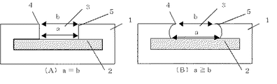
図1は、従来の塗工機の塗液の液溜め部と塗液吐出部の平面構造を示す一例として、従来のスリットダイコータのシムの断面図を示したものである。図1(A)は長方形形状のシム1、図1(B)は、特開2004−864号公報の曲線形状のシム1の例を示すものである。図1の斜線部は塗液の液溜め部2であり、塗液は、液溜め部2から塗液突出部3の先端部5に流れ出て、開口部4から基材等の対象面に塗布される。
FIG. 1 shows a sectional view of a shim of a conventional slit die coater as an example of a planar structure of a coating liquid reservoir and a coating liquid discharge unit of a conventional coating machine. 1A shows an example of a
図2は、本発明の塗工機の塗液の液溜め部2と塗液吐出部3の構造を示す一例として、スリットダイコータのシム1の断面図を示したものである。塗液吐出部3の開口幅bが、塗液の液溜め部2の開口幅aよりが広く、すなわち、a<bとなるように、段差状(A)、テーパー状(B)、R状(C)とする。この場合、形状は上記形状に限定されるものではない。
FIG. 2 shows a cross-sectional view of a
また、上記いずれの場合にしても、塗液吐出部3の先端部5の少なくとも1mmはストレート形状を有する。このときストレート形状部cの長さが2〜8mmの範囲であることが望ましい。上記の塗液吐出部の先端部5の少なくとも1mmがストレートでないと、塗液吐出部3の開口部4の端部は圧力が低下し、塗工面はダラダラとダレてしまい、平坦な塗工面が得られなくなる。
In any case, at least 1 mm of the
塗液吐出部3の厚みは、樹脂供給圧力の観点から、200〜800μmの範囲で設定されるが好ましい。塗液吐出部3の厚みが200μm未満では樹脂供給圧力が高すぎて吐出部及び液溜め部が変形しやすくなる傾向にあり、800μmを超えると逆に圧力が低く塗工時(特に凹凸面に塗工した場合)に気泡を巻き込みやすくなる傾向にある。
The thickness of the coating
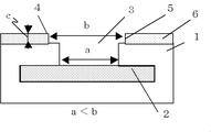
本発明の塗工機に用いられるシムの材質としては特に限定はないが、樹脂、金属などが好ましく、中でも剛性や精度の点を考慮すると、ステンレス鋼がより好ましく、SUS合金がより好ましい。また、従来の塗工機に塗工幅調整具を追加する等の手法によっても、本発明の塗工機は製造可能である。たとえば、図1(A)の従来のシムに塗工幅調整具6を追加し、塗工機の塗液の液溜め部2の開口幅a、塗液吐出部3の開口幅b、及び塗液吐出部3の先端部5の形状を本発明の範囲に調整した例を、図3に断面図で示す。
The material of the shim used in the coating machine of the present invention is not particularly limited, but resins, metals and the like are preferable. Among them, stainless steel is more preferable and SUS alloy is more preferable in consideration of rigidity and accuracy. Moreover, the coating machine of this invention can be manufactured also by the method of adding a coating width adjusting tool to the conventional coating machine. For example, a coating
本発明の塗工機は、塗工膜厚が100μm以上である場合にも好ましく、さらには、塗工膜厚が500μm以上であってもより好ましい。また、本発明の塗工機は、塗工対象面が凹凸を有する基材に塗液を塗工する場合にも、好適である。 The coating machine of the present invention is preferable even when the coating film thickness is 100 μm or more, and more preferably, the coating film thickness is 500 μm or more. Moreover, the coating machine of this invention is suitable also when coating a coating liquid on the base material whose coating object surface has an unevenness | corrugation.
以下、実施例に基づいて本発明を具体的に説明するがこれらに限定されるものではない。
以下、UV硬化樹脂を用いて500μmの塗布厚みにて塗工した場合について説明するが、樹脂物性、厚みに関してこれに限定されるものではない。
(実施例1)
塗工に用いる樹脂(塗液)は、供給タンクからポンプを用いて塗液の液溜め部に定量供給される。この場合、タンクを直接Airにて加圧するいわゆる圧空送液供給しても良い。上記ポンプ又はAir圧空により塗布厚み500μmに調整して塗液の液量を調整する。その後、塗液は液溜め部から塗液吐出部の先端開口部に流れ出て、基材(対象面)に塗布される。
EXAMPLES Hereinafter, although this invention is demonstrated concretely based on an Example, it is not limited to these.
Hereinafter, although the case where it coats with the application | coating thickness of 500 micrometers using UV hardening resin is demonstrated, it is not limited to this about resin physical property and thickness.
Example 1
The resin (coating liquid) used for coating is quantitatively supplied from the supply tank to the liquid reservoir of the coating liquid using a pump. In this case, a so-called pressurized air feeding liquid that directly pressurizes the tank with Air may be supplied. The amount of coating liquid is adjusted by adjusting the coating thickness to 500 μm using the pump or Air pressure. Thereafter, the coating liquid flows out from the liquid reservoir to the tip opening of the coating liquid discharge section, and is applied to the substrate (target surface).
東レエンジニアリング社製の塗工機を用い、400μm厚みのシムをスペーサーとして、アクリル系UV樹脂(粘度3000cps/25℃)を塗工した。この時の塗工圧力はポンプ回転数を調整して0.45MPaとした。その後、Si処理を施した東洋紡社製のカバーフィルムをSi処理面が塗工面側となるようにラミネートし、アイグラフィック社製のメタルハライドランプを用いて総照射量2000mJ/cm2でUVを照射し硬化させた。図2(A)の形状を有するシム1を用いて、スリットダイコータにより、上記方法により、ポリエチレンテレフタレート(PET)製の基材上に500μm厚みの塗工面を得た。
Using a coating machine manufactured by Toray Engineering Co., Ltd., an acrylic UV resin (viscosity 3000 cps / 25 ° C.) was applied using a 400 μm thick shim as a spacer. The coating pressure at this time was adjusted to 0.45 MPa by adjusting the pump rotation speed. Then, a Toyobo Co., Ltd. cover film that had been subjected to Si treatment was laminated so that the Si-treated surface was the coated surface side, and UV irradiation was performed using a metal halide lamp made by Eye Graphic with a total irradiation amount of 2000 mJ / cm 2. Cured. A coated surface having a thickness of 500 μm was obtained on a polyethylene terephthalate (PET) substrate by a slit die coater using the
(実施例2)
図2(B)の形状を有するシム1を用いた以外は実施例1と同様にして500μm厚みの塗工面を得た。
(Example 2)
A coated surface having a thickness of 500 μm was obtained in the same manner as in Example 1 except that the
(比較例1)
従来例の図1(B)の形状を有するシム1を用いた以外は実施例1と同様にして500μm厚みの塗工面を得た。
(Comparative Example 1)
A coated surface having a thickness of 500 μm was obtained in the same manner as in Example 1 except that the
実施例1、実施例2及び比較例1で得た塗工面の膜厚ばらつきと、塗工面端部の盛上がり量を、以下の通り、測定した。
接触式膜厚測定計(イトマン社製、ID−C112)により幅方向の膜厚ばらつきを測定した。測定は基材部/樹脂部/カバー部の総厚を測定しその後基材とカバーの厚みを補正し、樹脂塗工部のみの厚みとし幅方向両端部から100mmまでを5mm間隔、それ以外は50mm間隔で測定した。測定結果と、用いたシム形状を下記表1に示した。
The film thickness variation of the coated surface obtained in Example 1, Example 2 and Comparative Example 1 and the amount of swell at the edge of the coated surface were measured as follows.
The film thickness variation in the width direction was measured with a contact-type film thickness meter (ID-C112, manufactured by Itoman). Measurement is made by measuring the total thickness of the base part / resin part / cover part, and then correcting the thicknesses of the base part and the cover, with the thickness of only the resin coating part being 5 mm intervals from both ends in the width direction to 100 mm, otherwise Measurements were taken at 50 mm intervals. The measurement results and the shim shape used are shown in Table 1 below.

実施例1、2では、表1に示すとおり、膜厚ばらつきが少なく、良好な塗装面が得られた。図2(C)の形状を有する形状のシムを用いた場合も、実施例1と同様の結果が得られた。また、図2(A)、(B)及び(C)のシムを用いたスリットダイコータを用いて、凹凸面を有する基材を塗工したところ、膜厚ばらつきも耳高も少ない、良好な塗工面が得られた。さらに、間欠塗工を行った場合、液切れ性が良好であった。これに対して、比較例1では表1に示すとおり、塗工面が耳高を示した。図1(B)の形状を有する形状のシムを用いた場合も、比較例1と同様の結果が得られた。 In Examples 1 and 2, as shown in Table 1, there was little film thickness variation and a good coated surface was obtained. Even when a shim having the shape of FIG. 2C was used, the same result as in Example 1 was obtained. In addition, when a substrate having an uneven surface was applied using a slit die coater using shims of FIGS. 2A, 2B, and 2C, a good coating with little film thickness variation and low ear height was obtained. The work surface was obtained. Furthermore, when intermittent coating was performed, the liquid cutting property was good. In contrast, in Comparative Example 1, as shown in Table 1, the coated surface showed an ear height. Even when a shim having the shape of FIG. 1B was used, the same result as in Comparative Example 1 was obtained.
1:シム、2:塗液の液溜め部、3:塗液吐出部、4:塗液吐出部の開口部、5:塗液吐出部の先端部、6:塗工幅調整具
a:塗液の液溜め部の開口幅、b:塗液吐出部の開口幅、c:塗液吐出部の先端部のストレート形状部
1: Shim, 2: Liquid storage part for coating liquid, 3: Coating liquid discharge part, 4: Opening part of coating liquid discharge part, 5: Tip part of coating liquid discharge part, 6: Coating width adjusting tool a: Coating The opening width of the liquid reservoir part, b: the opening width of the coating liquid discharge part, c: the straight shape part at the tip of the coating liquid discharge part
Claims (4)
It is a coating method which coats a coating liquid on the coating object surface of a base material using the coating machine in any one of Claims 1-3, Comprising: The coating object surface of a base material has an unevenness | corrugation Method.
Priority Applications (1)
| Application Number | Priority Date | Filing Date | Title |
|---|---|---|---|
| JP2005079164A JP2006255643A (en) | 2005-03-18 | 2005-03-18 | Coating machine and coating method using it |
Applications Claiming Priority (1)
| Application Number | Priority Date | Filing Date | Title |
|---|---|---|---|
| JP2005079164A JP2006255643A (en) | 2005-03-18 | 2005-03-18 | Coating machine and coating method using it |
Publications (1)
| Publication Number | Publication Date |
|---|---|
| JP2006255643A true JP2006255643A (en) | 2006-09-28 |
Family
ID=37095429
Family Applications (1)
| Application Number | Title | Priority Date | Filing Date |
|---|---|---|---|
| JP2005079164A Pending JP2006255643A (en) | 2005-03-18 | 2005-03-18 | Coating machine and coating method using it |
Country Status (1)
| Country | Link |
|---|---|
| JP (1) | JP2006255643A (en) |
Cited By (7)
| Publication number | Priority date | Publication date | Assignee | Title |
|---|---|---|---|---|
| JP2011249305A (en) * | 2010-05-24 | 2011-12-08 | Samsung Sdi Co Ltd | Active material coating apparatus and coating method using the same |
| JP2013176748A (en) * | 2012-02-28 | 2013-09-09 | Samsung Sdi Co Ltd | Coating width adjustable slot die |
| JP2014233651A (en) * | 2013-05-31 | 2014-12-15 | オリジン電気株式会社 | Device and method of adhesive coating |
| CN111250354A (en) * | 2020-03-18 | 2020-06-09 | 天能帅福得能源股份有限公司 | Extrusion coating type die head gasket capable of eliminating coating edge effect |
| WO2021132992A1 (en) * | 2019-12-27 | 2021-07-01 | 주식회사 엘지에너지솔루션 | Electrode slurry-discharging shim allowing even coating, and coating die comprising same |
| WO2022097950A1 (en) * | 2020-11-03 | 2022-05-12 | 주식회사 엘지에너지솔루션 | Shim for die coater, die coater comprising same, and lithium secondary battery comprising cathode manufactured using same |
| EP4272877A1 (en) * | 2022-05-04 | 2023-11-08 | LG Energy Solution, Ltd. | Deposition system |
-
2005
- 2005-03-18 JP JP2005079164A patent/JP2006255643A/en active Pending
Cited By (13)
| Publication number | Priority date | Publication date | Assignee | Title |
|---|---|---|---|---|
| US9067229B2 (en) | 2010-05-24 | 2015-06-30 | Samsung Sdi Co., Ltd. | Active material coating apparatus and coating method using the same |
| JP2011249305A (en) * | 2010-05-24 | 2011-12-08 | Samsung Sdi Co Ltd | Active material coating apparatus and coating method using the same |
| JP2013176748A (en) * | 2012-02-28 | 2013-09-09 | Samsung Sdi Co Ltd | Coating width adjustable slot die |
| JP2014233651A (en) * | 2013-05-31 | 2014-12-15 | オリジン電気株式会社 | Device and method of adhesive coating |
| JP7442541B2 (en) | 2019-12-27 | 2024-03-04 | エルジー エナジー ソリューション リミテッド | Coating shim for discharging electrode slurry with excellent coating uniformity and coating die containing the same |
| US11951508B2 (en) | 2019-12-27 | 2024-04-09 | Lg Energy Solution, Ltd. | Electrode slurry-discharging shim allowing even coating, and coating die comprising same |
| WO2021132992A1 (en) * | 2019-12-27 | 2021-07-01 | 주식회사 엘지에너지솔루션 | Electrode slurry-discharging shim allowing even coating, and coating die comprising same |
| CN113543896A (en) * | 2019-12-27 | 2021-10-22 | 株式会社Lg新能源 | Coating pad for electrode paste discharge allowing uniform coating and coating die including the same |
| JP2022521016A (en) * | 2019-12-27 | 2022-04-04 | エルジー エナジー ソリューション リミテッド | Coating shim for discharging electrode slurry with excellent coating uniformity and coating die containing it |
| CN111250354B (en) * | 2020-03-18 | 2021-08-20 | 天能帅福得能源股份有限公司 | Extrusion coating type die head gasket capable of eliminating coating edge effect |
| CN111250354A (en) * | 2020-03-18 | 2020-06-09 | 天能帅福得能源股份有限公司 | Extrusion coating type die head gasket capable of eliminating coating edge effect |
| WO2022097950A1 (en) * | 2020-11-03 | 2022-05-12 | 주식회사 엘지에너지솔루션 | Shim for die coater, die coater comprising same, and lithium secondary battery comprising cathode manufactured using same |
| EP4272877A1 (en) * | 2022-05-04 | 2023-11-08 | LG Energy Solution, Ltd. | Deposition system |
Similar Documents
| Publication | Publication Date | Title |
|---|---|---|
| JP2006255643A (en) | Coating machine and coating method using it | |
| JP5463713B2 (en) | Doctor for gravure coating | |
| JP2000320544A (en) | Dynamic pressure bearing device, manufacture thereof and manufacture of coining punch used in the manufacture of dynamic pressure bearing device | |
| JP2007000730A (en) | Gravure coater | |
| KR102316972B1 (en) | Coating apparatus and method for producing coating film | |
| JP2007021415A (en) | Coating tool | |
| JP7289504B2 (en) | film applicator | |
| EP3730245A1 (en) | Abrasive member | |
| US20180264687A1 (en) | Metal molds for polymer microwedge fabrication | |
| JP5972932B2 (en) | Coating apparatus and coating method | |
| JP2005347508A (en) | Electronic component transferring method and transferring apparatus | |
| JP2011177977A (en) | Sliding member for printing, and printer | |
| JP5142937B2 (en) | Rolling roll and screen printing mesh | |
| KR20170063546A (en) | Blade device, and printer and coating apparatus provided with said blade device | |
| JP4802760B2 (en) | Coating rod and coating method and apparatus using the same | |
| JP4797458B2 (en) | Application method | |
| JP5520074B2 (en) | Coating resin liquid coating method and coating apparatus | |
| JP5857395B2 (en) | Gravure coating equipment | |
| JP4023784B2 (en) | Intaglio pick-up roll blade mechanism and offset printing method using the same | |
| JP2011067795A (en) | Block for coating head, coating head, coating apparatus, and method for manufacturing block for coating head | |
| JP2009083443A (en) | Pasty material filling squeegee, pasty material filling method and pasty material filling device | |
| JP2008229537A (en) | Die head and method of producting laminate | |
| KR102197516B1 (en) | Film cutting apparatus | |
| JP2008119656A (en) | Method for manufacturing coating film-formed sheet | |
| JP3964727B2 (en) | Processed film manufacturing method and apparatus |