JP2006247221A - Pulse wave detector - Google Patents
Pulse wave detector Download PDFInfo
- Publication number
- JP2006247221A JP2006247221A JP2005070165A JP2005070165A JP2006247221A JP 2006247221 A JP2006247221 A JP 2006247221A JP 2005070165 A JP2005070165 A JP 2005070165A JP 2005070165 A JP2005070165 A JP 2005070165A JP 2006247221 A JP2006247221 A JP 2006247221A
- Authority
- JP
- Japan
- Prior art keywords
- pulse wave
- function waveform
- correlation function
- waveform
- determined
- Prior art date
- Legal status (The legal status is an assumption and is not a legal conclusion. Google has not performed a legal analysis and makes no representation as to the accuracy of the status listed.)
- Withdrawn
Links
Images


Landscapes
- Measuring Pulse, Heart Rate, Blood Pressure Or Blood Flow (AREA)
Abstract
Description
本発明は、生体から発生する脈波を検出する脈波検出装置に関するものである。 The present invention relates to a pulse wave detection device that detects a pulse wave generated from a living body.
生体から脈波を検出して診断に利用する装置が種々提案されている。脈波に基づく診断の方法には種々の方法があり、たとえば、脈波の形状を反映する特徴値を用いる方法がある(たとえば特許文献1参照)。特許文献1では、脈波の特徴値として、脈波の立ち上がり点からピーク(最大点)までの時間であるU-timeなどの上昇特徴値や、脈波の先鋭度を算出し、それら上昇特徴値や先鋭度に基づいて、下肢動脈の狭窄を判定している。
Various devices for detecting a pulse wave from a living body and using it for diagnosis have been proposed. There are various methods of diagnosis based on a pulse wave, for example, a method using a feature value reflecting the shape of the pulse wave (see, for example, Patent Document 1). In
また、脈波に基づく別の診断方法として、脈波の立ち上がり点や脈波のピークなど所定の部位の発生時間や大きさを用いる方法がある(たとえば、前記特許文献1、特許文献2参照)。特許文献1では、脈波の立ち上がり点など所定部位の発生時間に基づいて、生体内を脈波が伝播する速度である脈波伝播速度を算出し、その脈波伝播速度を前述の上昇特徴値および先鋭度と同様に、下肢動脈の狭窄の判定に用いている。また、特許文献2では、脈波の立ち上がり点(すなわち最小点)およびピーク(すなわち最大点)の大きさから、予め決定された関係を用いて、連続的に血圧値を決定している。
As another diagnostic method based on the pulse wave, there is a method using the generation time and magnitude of a predetermined part such as the rising point of the pulse wave and the peak of the pulse wave (see, for example,
脈波に基づいて診断を行う場合、検出される脈波に体動などに起因するノイズが含まれていないことが必要となる。そのため、特許文献2では、逐次検出される脈波の振幅がその直前に検出された脈波の振幅に基づいて決定される所定範囲内であるか、または前回検出された脈波の振幅と今回の脈波の振幅との振幅差が、その直前に算出された振幅差に基づいて決定される所定範囲内であるかを判断することにより、体動によるノイズが含まれている脈波であるかどうかを判定している。
特許文献2の装置では、検出される脈波に混入するノイズの大きさがその脈波の振幅よりも小さい場合には、ノイズが発生したことを検出できない。しかし、脈波にノイズが混入する場合に、必ず脈波の振幅が大きく変化するとは限らず、ノイズが比較的小さい場合には、振幅はそれほど変化しないが、極大点の数が増えるなど、脈波の形状が変化する場合がある。そのように、ノイズによって脈波の形状が変化する場合にも、診断に悪影響を及ぼすことがある。 In the apparatus of Patent Document 2, when the magnitude of noise mixed in the detected pulse wave is smaller than the amplitude of the pulse wave, it cannot be detected that noise has occurred. However, when noise is mixed in the pulse wave, the amplitude of the pulse wave does not always change greatly. When the noise is relatively small, the amplitude does not change so much, but the number of local maximum points increases. The wave shape may change. As such, even when the pulse wave shape changes due to noise, the diagnosis may be adversely affected.
本発明は以上の事情を背景として為されたものであって、その目的とするところは、ノイズが含まれている脈波であるかどうかを精度良く判定できる脈波検出装置を提供することにある。 The present invention has been made against the background of the above circumstances, and the object of the present invention is to provide a pulse wave detection device that can accurately determine whether or not the pulse wave contains noise. is there.
前記目的を達成する為の本発明は、生体から脈波を検出する脈波センサと、その脈波センサにより検出された脈波の相関関数波形を決定する相関関数波形決定手段とを含むことを特徴とする脈波検出装置である。 The present invention for achieving the above object includes a pulse wave sensor for detecting a pulse wave from a living body, and a correlation function waveform determining means for determining a correlation function waveform of the pulse wave detected by the pulse wave sensor. This is a characteristic pulse wave detection device.
この発明によれば、相関関数波形決定手段により、脈波センサによって検出された脈波の相関関数波形が決定され、ノイズが混入することによって極大点が増加した脈波に基づいて決定される相関関数波形は、ノイズの少ない正常な脈波に基づいて決定される相関関数波形よりも極大点の多い複雑な形状の波形となるので、相関関数波形から脈波が正常に検出されたかどうかを精度良く判断することが可能となる。 According to this invention, the correlation function waveform determining means determines the correlation function waveform of the pulse wave detected by the pulse wave sensor, and the correlation is determined based on the pulse wave whose maximum point has increased due to the mixing of noise. The function waveform has a complex shape with more maximum points than the correlation function waveform determined based on the normal pulse wave with less noise, so it is accurate whether the pulse wave was detected normally from the correlation function waveform. It becomes possible to judge well.
ここで、前記相関関数波形決定手段により決定される相関関数波形は、相互相関関数波形でも良いが、自己相関関数波形であることが好ましい。その理由は、自己相関関数波形は同一の2つの脈波から決定されるので、自己相関関数波形の決定に用いられる両脈波には同じノイズが含まれる。従って、そのノイズに由来する自己相関関数波形の極大点が大きくなるので、脈波が正常に検出されたかどうかを判断しやすくなるからである。 Here, the correlation function waveform determined by the correlation function waveform determining means may be a cross correlation function waveform, but is preferably an autocorrelation function waveform. The reason is that since the autocorrelation function waveform is determined from the same two pulse waves, both pulse waves used for the determination of the autocorrelation function waveform contain the same noise. Therefore, the maximum point of the autocorrelation function waveform derived from the noise becomes large, and it is easy to determine whether or not the pulse wave is normally detected.
また、好ましくは、前記脈波検出装置は、前記相関関数波形決定手段により決定された相関関数波形を出力する出力装置を備える。このようにすれば、出力装置に出力された相関関数波形から、医師等が、脈波が正常に検出されたかどうかを判断することができる。 Preferably, the pulse wave detection device includes an output device that outputs the correlation function waveform determined by the correlation function waveform determination means. In this way, a doctor or the like can determine whether or not the pulse wave is normally detected from the correlation function waveform output to the output device.
また、好ましくは、前記脈波検出装置は、前記相関関数波形決定手段により決定された相関関数波形に基づいて、前記脈波センサにより検出された脈波が正常に検出されたかどうかを判定する検出結果判定手段を備えている。このようにすれば、脈波が正常に検出されたかどうかが自動的に判定されるので、ノイズを含んだ脈波に基づく誤った診断がされることが防止される。 Preferably, the pulse wave detection device detects whether or not the pulse wave detected by the pulse wave sensor is normally detected based on the correlation function waveform determined by the correlation function waveform determination means. A result judging means is provided. In this way, since it is automatically determined whether or not the pulse wave is detected normally, an erroneous diagnosis based on the pulse wave including noise is prevented.
上記検出結果判定手段による判定の方法としては、たとえば、前記相関関数波形の極大点の数に基づく判定方法や、前記相関関数波形のパワースペクトルに基づく判定方法がある。ノイズが多いほど脈波にノイズ由来の極大点が増えることから、相関関数波形にも極大点の数が増えるので、相関関数波形に存在する極大点の数が、予め設定された所定数以上である場合には、脈波が正常に検出されていないと判定することができる。また、相関関数波形に極大点の数が増えると、相関関数波形のパワースペクトルにもノイズ由来の成分が増えるので、相関関数波形のパワースペクトルからも、脈波が正常に検出されたかどうかを判定することができる。また、前記相関関数波形決定手段により決定される相関関数波形が相互相関関数波形である場合には、検出結果判定手段は、その相互相関関数波形の最大値を示す時点を基準とし、その最大値を示す時点よりもマイナス側の波形とプラス側の波形との相関係数に基づいて、前記脈波センサにより検出された脈波が正常に検出されたかどうかを判定することもできる。 Examples of the determination method by the detection result determination means include a determination method based on the number of local maximum points of the correlation function waveform and a determination method based on the power spectrum of the correlation function waveform. Since the number of local maximum points derived from noise increases in the pulse wave as the noise increases, the number of local maximum points also increases in the correlation function waveform. Therefore, the number of local maximum points existing in the correlation function waveform is greater than or equal to a preset number. In some cases, it can be determined that the pulse wave is not normally detected. Also, as the number of local maximum points in the correlation function waveform increases, noise-derived components also increase in the power spectrum of the correlation function waveform, so it is determined whether the pulse wave has been detected normally from the power spectrum of the correlation function waveform. can do. Further, when the correlation function waveform determined by the correlation function waveform determining means is a cross correlation function waveform, the detection result determining means is based on the time point indicating the maximum value of the cross correlation function waveform, and the maximum value It is also possible to determine whether or not the pulse wave detected by the pulse wave sensor has been detected normally based on the correlation coefficient between the waveform on the minus side and the waveform on the plus side of the time point.
以下、本発明の実施の形態を説明する。まず、本発明の一実施例を図面に基づいて説明する。本発明の脈波検出装置は種々の診断に利用することができるが、この実施例は、脈波検出装置を動脈の狭窄の診断に利用する狭窄診断装置である。図1は、その狭窄診断装置10の回路構成を示すブロック図である。
Embodiments of the present invention will be described below. First, an embodiment of the present invention will be described with reference to the drawings. The pulse wave detection device of the present invention can be used for various diagnoses. This embodiment is a stenosis diagnosis device that uses a pulse wave detection device for diagnosis of arterial stenosis. FIG. 1 is a block diagram showing a circuit configuration of the stenosis
図1において、カフ12は、一般的な足首用のカフであり、足首14に巻き着けられる。カフ12には、圧力センサ16および調圧弁18が配管20により接続されている。また、調圧弁18は配管21により空気ポンプ22と接続されている。上記カフ12は、布製帯状袋内にゴム製袋を収容した構造である。調圧弁18は、空気ポンプ22から供給される圧力の高い空気の圧力を調圧してカフ12内へ供給し、或いは、カフ12内の空気を排気することによりカフ12内の圧力を調圧する。
In FIG. 1, a
圧力センサ16は、カフ12内の圧力を検出してその圧力を表す圧力信号SPを静圧弁別回路24および脈波弁別回路26にそれぞれ供給する。静圧弁別回路24はローパスフィルタを備え、圧力信号SPに含まれる定常的な圧力すなわちカフ12の圧迫圧力(以下、この圧力をカフ圧PCという)を表すカフ圧信号SCを弁別して、そのカフ圧信号SCをA/D変換器28を介して電子制御装置30へ供給する。
The
脈波弁別回路26はバンドパスフィルタを備え、圧力信号SPの振動成分である脈波信号SMを周波数的に弁別してその脈波信号SMをA/D変換器32を介して電子制御装置30へ供給する。この脈波信号SMは足首14から検出される脈波すなわち足首脈波を表していることから、脈波信号SMを含む圧力信号SPを検出するカフ12が脈波センサとして機能している。
The pulse wave
上記電子制御装置30は、CPU34,ROM36,RAM38,および図示しないI/Oポート等を備えた所謂マイクロコンピュータにて構成されている。CPU34は、ROM36に予め記憶されたプログラムに従ってRAM38の記憶機能を利用しつつ信号処理を実行することにより、I/Oポートから駆動信号を出力して図示しない駆動回路を介して調圧弁18および空気ポンプ22を制御する。CPU34は、調圧弁18および空気ポンプ22を制御することにより、カフ12内の圧力を制御する。また、CPU34は、電子制御装置30に供給される信号を演算処理することにより、足首脈波が正常に検出されたかどうかの判定や、%MAPなどの狭窄関連情報の決定を行う。また、CPU34は、出力装置として機能する表示器40の表示内容を制御する。
The
図2は、電子制御装置30の制御機能の要部を示す機能ブロック線図である。カフ圧制御手段50は、図示しない測定開始ボタンが操作されると、静圧弁別回路24から供給されるカフ圧信号SCに基づいてカフ圧PCを判断しつつ、調圧弁18および空気ポンプ22を制御することにより、カフ圧PCを所定の脈波検出圧とする。この脈波検出圧は、カフ12が装着されている部位(すなわち足首14)における最低血圧値よりも低い圧力であって、且つ、脈波弁別回路26により弁別される脈波信号SMが十分な信号強度となるような圧力であり、たとえば50〜60mmHgに設定されている。
FIG. 2 is a functional block diagram showing the main part of the control function of the
脈波表示手段52は、カフ圧制御手段50によりカフ圧PCが上記脈波検出圧に制御されている状態で脈波弁別回路26から供給される一拍分の脈波信号SM、すなわち一拍分の足首脈波を、表示器40の所定位置に表示する。
The pulse wave display means 52 is a pulse wave signal SM for one beat supplied from the pulse
自己相関関数波形決定手段54は、カフ圧制御手段50によりカフ圧PCが上記脈波検出圧に制御されている状態で脈波弁別回路26から供給される一拍分の足首脈波信号SMの自己相関関数波形を決定し、決定した自己相関関数波形を表示器40に表示する。なお、上記自己相関関数波形は、式1に記述される自己相関関数R(τ)によって表される波形である。

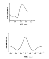
図3および図4は、上記脈波表示手段52および自己相関関数波形決定手段54により表示器40に表示される足首脈波および自己相関関数波形の一例を示す図であり、図3は、ノイズの少ない正常に検出された足首脈波およびそれから決定される自己相関関数波形を示し、図4は、ノイズが多い異常な足首脈波およびそれから決定される自己相関関数波形を示している。図3および図4から分かるように、正常な足首脈波から決定される自己相関関数波形は、極大点が一つしかない単純な形状の波形であるのに対して、正常に検出されなかった足首脈波から決定される自己相関関数波形は、複数の極大点があり複雑な形状の波形となっている。従って、医師等は、表示器40に表示される自己相関関数波形から、足首脈波が正常に検出されたかどうかを判断することができる。
3 and 4 are diagrams showing an example of an ankle pulse wave and an autocorrelation function waveform displayed on the
検出結果判定手段56は、脈波弁別回路26から供給された足首脈波が正常に検出された脈波であるかどうかを、自己相関関数波形決定手段54により決定された自己相関関数波形の極大点の数に基づいて判定する。すなわち、自己相関関数波形の極大点の数が所定数よりも少なければ、足首脈波は正常に検出されたと判定し、極大点の数が所定数(たとえば3つ)以上であれば、体動などのノイズにより足首脈波は正常に検出されなかったと判定する。
The detection
狭窄関連情報決定手段58は、脈波弁別回路26から供給される足首脈波に基づいて、血管の狭窄に関連する生体情報である狭窄関連情報を決定し、決定した狭窄関連情報を表示器40に表示する。狭窄関連情報としては、たとえば、前記特許文献1に記載されている上昇特徴値、先鋭度、脈波伝播速度情報などがあるが、本実施例では、上昇特徴値であるアップストロークタイム(upstroke time(以下、U-timeという))および先鋭度である%MAPを決定する。U-timeは、脈波の立ち上がり点からピーク(最大点)までの時間であり、%MAPは、脈波のピーク高さH(すなわち脈圧)に対する脈波面積Sの重心位置の高さGの割合(=100×H/G)である。これらU-timeや%MAPが表示器40に表示されると、その値から動脈の狭窄を判定することが可能となる。
Based on the ankle pulse wave supplied from the pulse
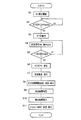
図5は、図2の機能ブロック線図に示した電子制御装置30の制御作動を説明するフローチャートである。まず、ステップ(以下、ステップを省略する)S1では、空気ポンプ22を起動させるとともに、調圧弁18を制御して、カフ圧PCの昇圧を開始する。続くS2では、カフ圧PCが脈波検出圧として設定された50mmHg以上となったか否かを判断する。このS2の判断が否定された場合は、S2の判断を繰り返し実行するが、肯定された場合には、続くS3において、調圧弁18を閉じることによりそのカフ圧PCを維持するとともに、空気ポンプ22を停止させる。
FIG. 5 is a flowchart for explaining the control operation of the
そして、続くS4では、カフ圧PCが維持されている状態で、脈波弁別回路26から供給される脈波信号SMを読み込み、続くS5では、脈波信号SMを一拍分読み込んだか否かを判断する。この判断が否定された場合には、前記S4を繰り返し実行することにより脈波信号SMの読み込みを継続するが、肯定された場合には、続くS6において、調圧弁18を解放することによりカフ圧PCを大気圧まで排圧する。図5では、S1乃至S3および上記S6がカフ圧制御手段50に相当する。
In the subsequent S4, the pulse wave signal SM supplied from the pulse
続くS7は脈波表示手段52に相当し、S4乃至S5の繰り返しにより読み込んだ一拍分の脈波信号SMが表す足首脈波を、たとえば前述の図3または図4に示すように、表示器40に表示する。 Subsequent S7 corresponds to the pulse wave display means 52, and the ankle pulse wave represented by the pulse wave signal SM for one beat read by repeating S4 to S5 is displayed as shown in FIG. 3 or FIG. 4, for example. 40.
続くS8は自己相関関数波形決定手段54に相当し、S4乃至S5の繰り返しにより読み込んだ一拍分の脈波信号SMに基づいて、前記式1から一拍分の足首脈波の自己相関関数波形を決定し、決定した自己相関関数波形を、たとえば前述の図3または図4に示すように、表示器40に表示する。
The subsequent S8 corresponds to the autocorrelation function
続くS9乃至S10は検出結果判定手段56に相当し、S9では、上記S8で決定した自己相関関数波形の極大点の数を決定し、その極大点の数が予め設定されている所定数(たとえば3つ)以上であれば、足首脈波は正常に検出されていないと判定し、極大点の数が所定数よりも少なければ、足首脈波は正常に検出されたと判定する。そして、続くS10では、S9で判定した結果を表示器40に表示する。
Subsequent S9 to S10 correspond to the detection result determination means 56. In S9, the number of local maximum points of the autocorrelation function waveform determined in S8 is determined, and the number of local maximum points is set to a predetermined number (for example, If three or more), it is determined that the ankle pulse wave is not normally detected, and if the number of local maximum points is less than the predetermined number, it is determined that the ankle pulse wave is normally detected. In subsequent S10, the result determined in S9 is displayed on the
続くS11は狭窄関連情報決定手段58に相当し、S4乃至S5の繰り返しにより読み込んだ一拍分の足首脈波に基づいて、U-timeおよび%MAPを決定する。すなわち、読み込んだ足首脈波の立ち上がり点およびピークを決定し、その立ち上がり点からピークまでの時間をU-timeとし、足首脈波の面積Sの重心位置高さGおよび足首脈波のピーク高さHを決定し、そのピーク高さHに対する脈波面積Sの重心位置高さGの割合(=100×H/G)を%MAPとして決定する。そして、決定したU-timeおよび%MAPを表示器40に表示する。
Subsequent S11 corresponds to the stenosis related
本装置10を用いた診断では、S8で表示された自己相関関数波形やS10で表示された検出結果から、足首脈波が正常に検出されたかどうかを判断した上で、上記S11により表示されたU-timeおよび%MAPや、前記S7で表示された足首脈波の形状から、狭窄の有無を判断する。
In the diagnosis using the
上述の実施例によれば、自己相関関数波形決定手段54(S8)により、カフ12によって検出された足首脈波の自己相関関数波形が決定され、ノイズが混入することによって極大点が増加した足首脈波に基づいて決定される自己相関関数波形は、ノイズの少ない正常な足首脈波に基づいて決定される自己相関関数波形よりも極大点の多い複雑な形状の波形となるので、自己相関関数波形から足首脈波が正常に検出されたかどうかを精度良く判断することが可能となる。
According to the above-described embodiment, the autocorrelation function waveform determining means 54 (S8) determines the autocorrelation function waveform of the ankle pulse wave detected by the
また、本実施例によれば、自己相関関数波形決定手段54(S8)により決定された自己相関関数波形が表示器40に表示されることから、その表示された自己相関関数波形から、医師等が、脈波が正常に検出されたかどうかを判断することができる。
Further, according to the present embodiment, since the autocorrelation function waveform determined by the autocorrelation function waveform determining means 54 (S8) is displayed on the
また、本実施例によれば、検出結果判定手段56(S9乃至S10)により、自己相関関数波形決定手段54(S8)によって決定された自己相関関数波形に基づいて、カフ12により検出された足首脈波が正常に検出されたかどうかが自動的に判定されるので、ノイズを含んだ足首脈波に基づく誤った診断がされることが防止される。
Further, according to this embodiment, the ankle detected by the
以上、本発明の一実施例を図面に基づいて説明したが、本発明は他の態様においても適用される。 As mentioned above, although one Example of this invention was described based on drawing, this invention is applied also in another aspect.
たとえば、前述の実施例の検出結果判定手段56では、自己相関関数波形の極大点の数に基づいて足首脈波が正常に検出されたかどうかを判定していたが、自己相関関数波形のパワースペクトルを求めて、そのパワースペクトルから、足首脈波が正常に検出されたかどうかを判定してもよい。図6は、そのパワースペクトルの一例を示す図であって、(a)は正常な足首脈波に基づいて決定された自己相関関数波形のパワースペクトルの一例であり、(b)はノイズが多く混入している正常でない足首脈波に基づいて決定された自己相関関数波形のパワースペクトルの一例である。ノイズが多く混入していると、図6(b)に示されるように、そのノイズに起因してパワースペクトルの高周波部分が増加して、高周波部分にピークが確認できることから、パワースペクトルから足首脈波が正常に検出されたかどうかを判定できるのである。
For example, the detection
また、前述の実施例では、相関関数波形として自己相関関数波形を決定していたが、それに代えて、相互相関関数波形を決定してもよい。なお、相互相関関数波形を決定するための2つの脈波は、異なる2つの部位からそれぞれ検出される2つの脈波であってもよいし、同一部位であるが検出時間が異なる2つの脈波であってもよい。図7は、検出部位が異なる2つの脈波(第1脈波x(t)および第2脈波y(t))、およびその2つの脈波から決定される相互相関関数波形を示す図である。なお、相互相関関数波形は、式2に記述される相互相関関数Rxy(τ)によって表される波形である。
相関関数波形として相互相関関数波形を決定する場合、その相互相関関数波形から、脈波センサにより検出された脈波が正常であるかどうかを判定する方法は、前述の自己相関関数波形と同様に、極大点の数に基づく方法や相関関数波形のパワースペクトルに基づく方法であってもよいが、相互相関関数波形の左右の対称性に基づく方法であってもよい。相互相関関数波形の左右の対称性に基づく方法とは、図7に例示したような相互相関関数波形をその最大値を示す時点(図7では時間τ=0)を基準点(0点)として左右に分けて、図8に示すように、左側波形(すなわちマイナス側の波形)L(τ)と右側波形(すなわちプラス側の波形)R(τ)とし、その左側波形L(τ)と右側波形R(τ)との相関係数cを求め、その相関係数cが所定値よりも低い場合には、脈波検出が正常に行われなかったと判定する方法である。 When determining the cross-correlation function waveform as the correlation function waveform, the method for determining whether or not the pulse wave detected by the pulse wave sensor is normal from the cross-correlation function waveform is the same as the autocorrelation function waveform described above. A method based on the number of local maximum points or a method based on the power spectrum of the correlation function waveform may be used, but a method based on the left-right symmetry of the cross-correlation function waveform may also be used. The method based on the left-right symmetry of the cross-correlation function waveform refers to the time point (time τ = 0 in FIG. 7) at which the cross-correlation function waveform illustrated in FIG. As shown in FIG. 8, the left waveform (that is, the negative waveform) L (τ) and the right waveform (that is, the positive waveform) R (τ) are divided into the left and right waveforms, as shown in FIG. In this method, a correlation coefficient c with the waveform R (τ) is obtained, and when the correlation coefficient c is lower than a predetermined value, it is determined that the pulse wave detection has not been performed normally.
なお、上記相関係数cは0と1の間の値であるが、第1脈波xおよび第2脈波yともにノイズの混入が少ない場合には、第1脈波xと第2脈波yとは比較的似た形状となるので、相互相関関数波形の左側波形L(τ)と右側波形R(τ)は比較的高い対称性を示し、相関係数cは1に近い値となる。一方、第1脈 波xおよび第2脈波yの一方にノイズが混入して、第1脈波xの形状と第2脈波yの形状とは比較的大きく異なると、相互相関関数波形の左側波形L(τ)の形状と右側波形R(τ)の形状は比較的大きく異なるので、相関係数cは1よりも十分に小さい値となる。従って、脈波検出が正常に行われたかどうかを判断するための所定値は、1よりも小さい範囲で1に比較的近い値に設定される。 The correlation coefficient c is a value between 0 and 1, but when there is little noise mixing in both the first pulse wave x and the second pulse wave y, the first pulse wave x and the second pulse wave Since y has a relatively similar shape, the left waveform L (τ) and the right waveform R (τ) of the cross-correlation function waveform show relatively high symmetry, and the correlation coefficient c is close to 1. . On the other hand, if noise is mixed in one of the first pulse wave x and the second pulse wave y and the shape of the first pulse wave x and the shape of the second pulse wave y are relatively different, Since the shape of the left waveform L (τ) and the shape of the right waveform R (τ) are relatively different, the correlation coefficient c is a value sufficiently smaller than 1. Therefore, the predetermined value for determining whether or not the pulse wave detection is normally performed is set to a value relatively close to 1 within a range smaller than 1.
また、前述の実施例では、図3および図4に示すように、時間τがマイナスである領域についても自己相関関数波形が示されているが、相関関数が自己相関関数である場合には、相関関数波形は時間τ=0を中心として対称となるので、時間τがマイナスである領域の波形を決定しなくてもよい。 In the above-described embodiment, as shown in FIGS. 3 and 4, the autocorrelation function waveform is also shown for the region where the time τ is negative. However, when the correlation function is an autocorrelation function, Since the correlation function waveform is symmetric with respect to time τ = 0, it is not necessary to determine the waveform in the region where time τ is negative.
また、前述の実施例では、脈波を検出した場合には、その脈波に基づいて必ず狭窄関連情報を決定していたが、検出結果判定手段56により正常に検出されたと判定された場合にのみ、その脈波から狭窄関連情報を決定するようになっていてもよい。
In the above-described embodiment, when the pulse wave is detected, the stenosis related information is always determined based on the pulse wave. However, when the detection
また、前述の実施例では、一拍分の脈波を検出していたが、複数拍分の脈波を検出し、その複数拍分の脈波から狭窄関連情報をそれぞれ決定してもよい。なお、そのように複数拍分の脈波を用いる場合、すべての脈波に基づいて狭窄関連情報を決定してもよいし、前述のように、正常に検出されたと判定された脈波についてのみ狭窄関連情報を決定してもよい。 In the above-described embodiment, a pulse wave for one beat is detected. However, pulse waves for a plurality of beats may be detected, and stenosis related information may be determined from the pulse waves for the plurality of beats. In addition, when using pulse waves for a plurality of beats as described above, stenosis-related information may be determined based on all pulse waves, or as described above, only for pulse waves that are determined to be normally detected. Stenosis related information may be determined.
また、前述の実施例では、カフ12が脈波センサとして機能していたが、脈波センサは前述の実施例のものに限定されず、押圧面に備えられた感圧素子により圧脈波を検出する型式など、圧脈波を検出する圧脈波センサを用いることもでき、また、酸素飽和度測定用の光電脈波検出プローブ、脈拍検出などのために指尖部などに装着される光電脈波センサなど、容積脈波を検出するセンサなどを用いることもできる。
In the above-described embodiment, the
また、前述の実施例では、脈波を検出する部位は足首14であったが、頸部など他の部位で脈波を検出してもよい。なお、正常に検出された脈波同士であっても検出部位によって極大点の数は異なるので、脈波の検出部位が異なれば、相関関数波形の極大点の数も異なる。従って、相関関数波形の極大点の数に基づいて、検出された脈波が正常であるかどうかを判断する場合、相関関数波形の極大点の数が幾つより少なければ正常であるかは、脈波の検出部位によって異なる。
In the above-described embodiment, the part for detecting the pulse wave is the
以上、本発明の実施の形態を説明したが、本発明は前述の実施の形態に限定されず、当業者の知識に基づいて種々の変更、改良を加えた態様で実施することができる。 Although the embodiments of the present invention have been described above, the present invention is not limited to the above-described embodiments, and can be implemented in variously modified and improved forms based on the knowledge of those skilled in the art.
10:狭窄診断装置(脈波検出装置)
12:カフ(脈波センサ)
40:表示器(出力装置)
52:脈波表示手段
54:自己相関関数波形決定手段
56:検出結果判定手段
10: Stenosis diagnosis device (pulse wave detection device)
12: Cuff (pulse wave sensor)
40: Display (output device)
52: Pulse wave display means 54: Autocorrelation function waveform determination means 56: Detection result determination means
Claims (8)
該脈波センサにより検出された脈波の相関関数波形を決定する相関関数波形決定手段と
を含むことを特徴とする脈波検出装置。 A pulse wave sensor for detecting a pulse wave from a living body;
And a correlation function waveform determining means for determining a correlation function waveform of the pulse wave detected by the pulse wave sensor.
前記相関関数波形決定手段により決定された相関関数波形を出力する出力装置をさらに含むことを特徴とする脈波検出装置。 The pulse wave detection device according to any one of claims 1 to 3,
The pulse wave detection device further comprising an output device for outputting the correlation function waveform determined by the correlation function waveform determination means.
前記相関関数波形決定手段により決定された相関関数波形に基づいて、前記脈波センサにより検出された脈波が正常に検出されたかどうかを判定する検出結果判定手段をさらに含むことを特徴とする脈波検出装置。 The pulse wave detection device according to any one of claims 1 to 4,
The pulse further comprising detection result determination means for determining whether or not the pulse wave detected by the pulse wave sensor is normally detected based on the correlation function waveform determined by the correlation function waveform determination means. Wave detector.
前記検出結果判定手段は、前記相関関数波形の極大点の数に基づいて、前記脈波センサにより検出された脈波が正常に検出されたかどうかを判定するものであることを特徴とする脈波検出装置。 The pulse wave detection device according to claim 5,
The detection result determining means determines whether or not the pulse wave detected by the pulse wave sensor is normally detected based on the number of maximum points of the correlation function waveform. Detection device.
前記検出結果判定手段は、前記相関関数波形のパワースペクトルに基づいて、前記脈波センサにより検出された脈波が正常に検出されたかどうかを判定するものであることを特徴とする脈波検出装置。 The pulse wave detection device according to claim 5,
The detection result determining means determines whether or not the pulse wave detected by the pulse wave sensor is normally detected based on a power spectrum of the correlation function waveform. .
前記相関関数波形決定手段により決定された相互相関関数波形の最大値を示す時点を基準とし、該最大値を示す時点よりもマイナス側の波形とプラス側の波形との相関係数に基づいて、前記脈波センサにより検出された脈波が正常に検出されたかどうかを判定する検出結果判定手段をさらに含むことを特徴とする脈波検出装置。
The pulse wave detection device according to claim 3,
Based on the correlation coefficient between the waveform on the minus side and the waveform on the plus side with respect to the time point indicating the maximum value of the cross correlation function waveform determined by the correlation function waveform determining means, The pulse wave detection device further comprising a detection result determination means for determining whether or not the pulse wave detected by the pulse wave sensor is normally detected.
Priority Applications (1)
| Application Number | Priority Date | Filing Date | Title |
|---|---|---|---|
| JP2005070165A JP2006247221A (en) | 2005-03-11 | 2005-03-11 | Pulse wave detector |
Applications Claiming Priority (1)
| Application Number | Priority Date | Filing Date | Title |
|---|---|---|---|
| JP2005070165A JP2006247221A (en) | 2005-03-11 | 2005-03-11 | Pulse wave detector |
Publications (1)
| Publication Number | Publication Date |
|---|---|
| JP2006247221A true JP2006247221A (en) | 2006-09-21 |
Family
ID=37088291
Family Applications (1)
| Application Number | Title | Priority Date | Filing Date |
|---|---|---|---|
| JP2005070165A Withdrawn JP2006247221A (en) | 2005-03-11 | 2005-03-11 | Pulse wave detector |
Country Status (1)
| Country | Link |
|---|---|
| JP (1) | JP2006247221A (en) |
Cited By (7)
| Publication number | Priority date | Publication date | Assignee | Title |
|---|---|---|---|---|
| WO2011052651A1 (en) * | 2009-10-30 | 2011-05-05 | オムロンヘルスケア株式会社 | Pulse wave analyzer and recording medium |
| JP2014073159A (en) * | 2012-10-02 | 2014-04-24 | Fujitsu Ltd | Pulse wave detector, pulse wave-detecting program, and pulse wave detecting-method |
| WO2014155750A1 (en) * | 2013-03-29 | 2014-10-02 | 富士通株式会社 | Blood flow index calculation method, blood flow index calculation program and blood flow index calculation device |
| WO2016203862A1 (en) * | 2015-06-15 | 2016-12-22 | フォスター電機株式会社 | Signal processing method, biosignal processing method, signal processing device, and biosignal processing device |
| WO2017085896A1 (en) * | 2015-11-20 | 2017-05-26 | 富士通株式会社 | Information processing device, information processing method, and information processing program |
| WO2017085894A1 (en) * | 2015-11-20 | 2017-05-26 | 富士通株式会社 | Pulse wave analysis device, pulse wave analysis method, and pulse wave analysis program |
| WO2018062323A1 (en) * | 2016-09-27 | 2018-04-05 | 京セラ株式会社 | Electronic device, control method, and program |
-
2005
- 2005-03-11 JP JP2005070165A patent/JP2006247221A/en not_active Withdrawn
Cited By (20)
| Publication number | Priority date | Publication date | Assignee | Title |
|---|---|---|---|---|
| RU2570282C2 (en) * | 2009-10-30 | 2015-12-10 | Омрон Хэлткэа Ко., Лтд. | Pulse wave analyser and record medium |
| JP2011092556A (en) * | 2009-10-30 | 2011-05-12 | Omron Healthcare Co Ltd | Pulse wave analyzer and pulse wave analysis program |
| CN102469942A (en) * | 2009-10-30 | 2012-05-23 | 欧姆龙健康医疗事业株式会社 | Pulse wave analyzer and recording medium |
| DE112010004170T5 (en) | 2009-10-30 | 2012-10-04 | Omron Healthcare Co., Ltd. | Pulse wave analysis device and recording medium |
| WO2011052651A1 (en) * | 2009-10-30 | 2011-05-05 | オムロンヘルスケア株式会社 | Pulse wave analyzer and recording medium |
| US9044145B2 (en) | 2009-10-30 | 2015-06-02 | Omron Healthcare Co., Ltd. | Pulse wave analysis device and recording medium |
| JP2014073159A (en) * | 2012-10-02 | 2014-04-24 | Fujitsu Ltd | Pulse wave detector, pulse wave-detecting program, and pulse wave detecting-method |
| JPWO2014155750A1 (en) * | 2013-03-29 | 2017-02-16 | 富士通株式会社 | Blood flow index calculation method, blood flow index calculation program, and blood flow index calculation device |
| WO2014155750A1 (en) * | 2013-03-29 | 2014-10-02 | 富士通株式会社 | Blood flow index calculation method, blood flow index calculation program and blood flow index calculation device |
| US10292602B2 (en) | 2013-03-29 | 2019-05-21 | Fujitsu Limited | Blood flow index calculating method, blood flow index calculating apparatus, and recording medium |
| WO2016203862A1 (en) * | 2015-06-15 | 2016-12-22 | フォスター電機株式会社 | Signal processing method, biosignal processing method, signal processing device, and biosignal processing device |
| JP2017000625A (en) * | 2015-06-15 | 2017-01-05 | フォスター電機株式会社 | Signal processing method, biological signal processing method, signal processing device, and biological signal processing device |
| WO2017085896A1 (en) * | 2015-11-20 | 2017-05-26 | 富士通株式会社 | Information processing device, information processing method, and information processing program |
| WO2017085894A1 (en) * | 2015-11-20 | 2017-05-26 | 富士通株式会社 | Pulse wave analysis device, pulse wave analysis method, and pulse wave analysis program |
| JPWO2017085896A1 (en) * | 2015-11-20 | 2018-07-26 | 富士通株式会社 | Information processing apparatus, information processing method, and information processing program |
| JPWO2017085894A1 (en) * | 2015-11-20 | 2018-08-02 | 富士通株式会社 | Pulse wave analyzer, pulse wave analysis method, and pulse wave analysis program |
| US20180256046A1 (en) * | 2015-11-20 | 2018-09-13 | Fujitsu Limited | Pulse wave analysis apparatus, pulse wave analysis method, and non-transitory computer-readable storage medium |
| US10743783B2 (en) | 2015-11-20 | 2020-08-18 | Fujitsu Limited | Pulse wave analysis apparatus, pulse wave analysis method, and non-transitory computer-readable storage medium |
| WO2018062323A1 (en) * | 2016-09-27 | 2018-04-05 | 京セラ株式会社 | Electronic device, control method, and program |
| JP2018050812A (en) * | 2016-09-27 | 2018-04-05 | 京セラ株式会社 | Electronic device, control method, and program |
Similar Documents
| Publication | Publication Date | Title |
|---|---|---|
| US6845263B2 (en) | Heart-sound detecting apparatus and pulse-wave-propagation-velocity-relating-information obtaining system using the heart-sound detecting apparatus | |
| US6796946B2 (en) | Arteriostenosis inspecting apparatus and ankle-blood-pressure measuring apparatus | |
| JP2006247221A (en) | Pulse wave detector | |
| JP3590613B2 (en) | Amplitude increase index calculation device and arteriosclerosis test device | |
| EP1319363A1 (en) | Arteriosclerosis diagnosing apparatus | |
| JP2007007075A (en) | Blood pressure measuring apparatus | |
| JP3697241B2 (en) | Atherosclerosis evaluation device | |
| JP2002272688A (en) | Ankle-brachial blood pressure index measuring apparatus | |
| US6969355B2 (en) | Arteriostenosis diagnosing apparatus | |
| JP3603036B2 (en) | Automatic blood pressure measurement device | |
| JP5041155B2 (en) | Blood pressure measurement device | |
| JP3621394B2 (en) | Atherosclerosis evaluation device | |
| JP2003199718A (en) | Arterial sclerosis evaluation apparatus | |
| US20040171941A1 (en) | Blood flow amount estimating apparatus | |
| JP2003116800A (en) | Waveform characteristic point determining device and pulse wave propagation velocity information measuring device using this waveform characteristic point determining device | |
| JP3952082B2 (en) | Blood pressure monitoring device | |
| EP1410757A1 (en) | Vital-information obtaining apparatus | |
| JP3697239B2 (en) | Upper limb artery stenosis evaluation device | |
| JP2007185320A (en) | Constriction estimating apparatus | |
| JP3975604B2 (en) | Arteriosclerosis measuring device | |
| JP2004049331A (en) | Arteriosclerosis diagnosing system | |
| JP2009125316A (en) | Blood pressure monitor system | |
| JP2007020749A (en) | Blood pressure measuring method and blood pressure measuring device | |
| JP2009125317A (en) | Blood pressure monitor system | |
| JP2004073722A (en) | Cuff pulse wave detector and pulse wave propagation velocity information measuring device |
Legal Events
| Date | Code | Title | Description |
|---|---|---|---|
| A300 | Withdrawal of application because of no request for examination |
Free format text: JAPANESE INTERMEDIATE CODE: A300 Effective date: 20080513 |