JP2006246830A - Partitioning material of tree-planting area, partitioning structure and tree-planting facility - Google Patents
Partitioning material of tree-planting area, partitioning structure and tree-planting facility Download PDFInfo
- Publication number
- JP2006246830A JP2006246830A JP2005070461A JP2005070461A JP2006246830A JP 2006246830 A JP2006246830 A JP 2006246830A JP 2005070461 A JP2005070461 A JP 2005070461A JP 2005070461 A JP2005070461 A JP 2005070461A JP 2006246830 A JP2006246830 A JP 2006246830A
- Authority
- JP
- Japan
- Prior art keywords
- partition
- greening
- greening area
- planting
- partitioning
- Prior art date
- Legal status (The legal status is an assumption and is not a legal conclusion. Google has not performed a legal analysis and makes no representation as to the accuracy of the status listed.)
- Pending
Links
Images


Classifications
-
- Y—GENERAL TAGGING OF NEW TECHNOLOGICAL DEVELOPMENTS; GENERAL TAGGING OF CROSS-SECTIONAL TECHNOLOGIES SPANNING OVER SEVERAL SECTIONS OF THE IPC; TECHNICAL SUBJECTS COVERED BY FORMER USPC CROSS-REFERENCE ART COLLECTIONS [XRACs] AND DIGESTS
- Y02—TECHNOLOGIES OR APPLICATIONS FOR MITIGATION OR ADAPTATION AGAINST CLIMATE CHANGE
- Y02A—TECHNOLOGIES FOR ADAPTATION TO CLIMATE CHANGE
- Y02A30/00—Adapting or protecting infrastructure or their operation
- Y02A30/24—Structural elements or technologies for improving thermal insulation
- Y02A30/254—Roof garden systems; Roof coverings with high solar reflectance
-
- Y—GENERAL TAGGING OF NEW TECHNOLOGICAL DEVELOPMENTS; GENERAL TAGGING OF CROSS-SECTIONAL TECHNOLOGIES SPANNING OVER SEVERAL SECTIONS OF THE IPC; TECHNICAL SUBJECTS COVERED BY FORMER USPC CROSS-REFERENCE ART COLLECTIONS [XRACs] AND DIGESTS
- Y02—TECHNOLOGIES OR APPLICATIONS FOR MITIGATION OR ADAPTATION AGAINST CLIMATE CHANGE
- Y02B—CLIMATE CHANGE MITIGATION TECHNOLOGIES RELATED TO BUILDINGS, e.g. HOUSING, HOUSE APPLIANCES OR RELATED END-USER APPLICATIONS
- Y02B80/00—Architectural or constructional elements improving the thermal performance of buildings
- Y02B80/32—Roof garden systems
Landscapes
- Cultivation Of Plants (AREA)
Abstract
Description
本発明は、建築物の屋上、屋根、ベランダ等に形成する緑化エリアと非緑化エリアとを仕切る仕切材及び仕切構造、並びに仕切材を有する緑化設備に関する。 The present invention relates to a partition material and a partition structure for partitioning a greening area and a non-greening area formed on a rooftop, a roof, a veranda or the like of a building, and a greening facility having the partitioning material.
建築物の屋上、屋根、ベランダ等に形成する緑化エリアと非緑化エリアとを仕切る仕切構造や緑化設備に関する技術として、特許文献1のバルコニー等の緑化設備がある。特許文献1の緑化設備は、防水処理を施したバルコニー又は屋上の床面の一部に植物を植えた緑化ユニットを載置し、緑化ユニットを載置した載置部とその他の床面との境界部に、前記緑化ユニットより高く且つ上部に載置部側に突出する突出部が形成された仕切部を設け、緑化ユニットと仕切部との隙間を隠すものである。 As a technique related to a partitioning structure and a greening facility for partitioning a greening area and a non-greening area formed on a rooftop, a roof, a veranda or the like of a building, there is a greening facility such as a balcony of Patent Document 1. In the greening facility of Patent Document 1, a greening unit in which a plant is planted is placed on a part of a floor surface of a balcony or rooftop that has been waterproofed, and a placement unit on which the greening unit is placed and other floor surfaces. A partition portion is provided at the boundary portion, which is higher than the greening unit and has a protruding portion formed on the upper portion that protrudes toward the placement portion, and hides the gap between the greening unit and the partitioning portion.
その他の関連技術として、特許文献2には、陸屋根床面などの床面に敷設され、芝、庭木、花などの植物が植えられる植生マットの周りを囲む庭園フレームで、床面に設けられる断面上向きコ字状のベースと、このベースに上側から嵌まる断面下向きコ字状のカバーとからなり、ベース内に配管を配設するものが開示されている。 As another related technique, Patent Document 2 discloses a cross-section provided on a floor surface in a garden frame that is laid on a floor surface such as a flat roof floor and surrounds a vegetation mat on which plants such as grass, garden trees, and flowers are planted. There is disclosed an upper U-shaped base and a cross-sectionally downward U-shaped cover that is fitted to the base from above, and a pipe is disposed in the base.
ところで、特許文献1の構成は、仕切部やその突出部と緑化ユニットとの間に空間が形成され、仕切部やその突出部と緑化ユニットとが分離して設けられることから、風通しの良い場所など設置した場合に、緑化エリア内に入り込んだ風等で緑化ユニットが飛散してしまう不具合がある。斯様な緑化ユニットの飛散は、仕切部の近傍ではより風の影響を受けやすくなるため、より高い確率で発生する。更に、特許文献2の構成も、植生マットの周りに単に庭園フレームを設けるものであるため、仮に緑化ユニットの周りに庭園フレームを設けた場合、同様に緑化ユニットが飛散する不具合を生ずる。 By the way, since the structure of patent document 1 has a space formed between a partition part or its protrusion part, and a greening unit, and a partition part, its protrusion part, and a greening unit are provided separately, a place with good ventilation When installed, etc., there is a problem that the greening unit is scattered by the wind entering the greening area. Such scattering of the greening unit is more likely to be affected by the wind in the vicinity of the partition, and therefore occurs with a higher probability. Furthermore, since the configuration of Patent Document 2 also simply provides a garden frame around the vegetation mat, if a garden frame is provided around the greening unit, the problem of the greening unit scattering similarly occurs.
また、特許文献1の構成は、潅水設備や配線設備を施す場合に、配管や配線を外部に剥き出しに配置するか、或いは別途に配管や配線の経路を形成する必要があるため、美観が損なわれるという不具合もある。他方で、特許文献2の構成は、潅水設備を設ける場合にベース内に配管を配設することができるので、美観が損なわれることを防止することが可能である。しかし、緑化エリアの広さによっては複数の配管や太い配管を配設することが必要になるが、斯様な場合にベースの幅を広くすることが必要となるため、緑化エリアの広さに応じて様々な広さのベースやカバーを用意しなければならなくなり、緑化設備が高コスト化する。 In addition, in the configuration of Patent Document 1, when irrigation equipment or wiring equipment is provided, it is necessary to arrange piping or wiring to be exposed to the outside, or to separately form piping or wiring paths, so that the aesthetics are impaired. There is also a problem that it is. On the other hand, the configuration of Patent Document 2 can prevent piping from being spoiled because piping can be disposed in the base when irrigation equipment is provided. However, depending on the size of the greening area, it may be necessary to install multiple pipes or thick pipes. In such a case, it is necessary to increase the width of the base. Accordingly, bases and covers of various sizes have to be prepared, and the greening facilities are expensive.
本発明は上記課題に鑑みて提案するものであって、緑化エリア内の緑化ユニットが風等で飛散することを安価に防止することができる緑化エリアの仕切材及び仕切構造、並びに前記仕切材を有する緑化設備を提供することを目的とする。また、本発明の他の目的は、緑化エリアの優れた美観を確保すると共に、緑化エリアの広さに応じた配管や配線の配設に適応する設置スペースを安価に実現することにある。 This invention proposes in view of the said subject, Comprising: The partition material and partition structure of the greening area which can prevent the greening unit in a greening area from scattering with a wind etc. cheaply, and the said partition material The purpose is to provide a greening facility. Another object of the present invention is to ensure an excellent aesthetics of the greening area and to realize an inexpensive installation space adapted to the arrangement of piping and wiring according to the size of the greening area.
本発明の緑化エリアの仕切材は、緑化ユニットを敷設して形成される緑化エリアの外縁近傍に固定され、緑化エリアと非緑化エリアとを仕切ると共に、緑化エリアの外縁を上方から押圧する押圧片を有することを特徴とし、又、本発明の緑化エリアの仕切構造は、前記仕切材を有することを特徴とする。前記仕切材は、押圧片から屈曲して下方に延設される側壁と、側壁下端から屈曲して側方へ延設され、緑化エリアの外縁近傍に固定される固定片とを有するものとすると好適であり、更に、例えば押圧片と側壁と固定片とが断面略Z字形に一体として形成されているものとするとより好適である。 The partition material of the greening area of the present invention is fixed near the outer edge of the greening area formed by laying the greening unit, partitions the greening area and the non-greening area, and presses the outer edge of the greening area from above In addition, the partition structure of the greening area of the present invention is characterized by having the partition material. The partition material has a side wall that is bent from the pressing piece and extends downward, and a fixing piece that is bent from the lower end of the side wall and extends to the side and is fixed near the outer edge of the greening area. Further, for example, it is more preferable that the pressing piece, the side wall, and the fixed piece are integrally formed in a substantially Z-shaped cross section.
また、本発明の緑化エリアの仕切構造は、緑化ユニットを敷設して形成される緑化エリアと非緑化エリアとを仕切る仕切構造であって、緑化エリアの外縁近傍に仕切材が固定され、仕切材から所定距離離間して外壁材が配設され、仕切材と該外壁材との間にカバー材が覆設されることを特徴とする。更に、前記仕切構造は、前記仕切材と外壁材とを同一部材とする構成、或いは前記仕切材とカバー材と外壁材に囲まれた空間を、配管若しくは配線若しくはその双方を配設する空間とする構成、或いは前記仕切材が、その相互間に所定の隙間を形成して配設されている構成とすると好適である。 The partitioning structure of the greening area of the present invention is a partitioning structure for partitioning a greening area formed by laying a greening unit and a non-greening area, and the partitioning material is fixed in the vicinity of the outer edge of the greening area. An outer wall material is disposed at a predetermined distance from the outer wall material, and a cover material is provided between the partition material and the outer wall material. Further, the partition structure is configured such that the partition member and the outer wall member are the same member, or a space surrounded by the partition member, the cover member, and the outer wall member is a space in which piping or wiring or both are disposed. It is preferable that the partitioning material or the partitioning material is disposed with a predetermined gap therebetween.
また、本発明の緑化設備は、緑化ユニットを構成する箱形植栽部の側壁に、該箱形植栽部と隣接する別の箱形植栽部の側壁とを連係する連係構造が設けられ、隣接する箱形植栽部が相互に連係されて緑化エリアが構成されると共に、緑化エリアの外縁近傍に仕切構造が設けられることを特徴とする。前記連係構造は、例えば箱形植栽部の側壁の上端付近に外方へ突出する略鉤形の突出片を形成し、略鉤形突出片を隣接する箱形植栽部の側壁上端或いは前記側壁上端付近に形成された凹部に上方から引っ掛けて係合する構造や、或いは箱形植栽部の側壁外面に凸部を形成し、これと隣接する箱形植栽部の側壁外面に凹部を形成し、凸部と凹部を係合する構造等とすることが可能である。 Further, the greening facility of the present invention is provided with a linkage structure that links the side wall of the box-shaped planting unit and the side wall of another box-shaped planting unit adjacent to the side wall of the box-shaped planting unit constituting the greening unit. The adjacent box-shaped planting parts are linked to each other to form a greening area, and a partition structure is provided in the vicinity of the outer edge of the greening area. The linkage structure is formed, for example, in the vicinity of the upper end of the side wall of the box-shaped planting part, forming a substantially bowl-shaped protruding piece that protrudes outwardly, and the upper end of the side wall of the adjacent box-shaped planting part or the A structure that hooks and engages with a recess formed near the upper end of the side wall from above, or a convex portion is formed on the outer side wall of the box-shaped planting portion, and a concave portion is formed on the outer side wall of the box-shaped planting portion adjacent thereto. It is possible to form a structure that engages the convex portion and the concave portion.
更に、本発明の緑化設備は、折板屋根の山部相互間に下地材が架設され、緑化エリアの外縁に対応する位置の下地材に折板屋根の谷部の一部を覆うカバー部が設けられると共に、該下地材上に敷設されることを特徴とする。前記下地材は、例えば断面略コ字形のチャンネル部材や四角柱形等の棒材等、更に前記緑化エリアの外縁の対応位置に配設される下地材は、前記棒材に一体若しくは別体でカバー部が形成されたもの等とすることが可能であり、又、カバー部は、例えば谷部の底との間に若干の排水用の隙間が形成される程度の略台形の板状部等とすることが可能である。 Furthermore, in the greening facility of the present invention, a base material is installed between the mountain parts of the folded plate roof, and a cover part covering a part of the valley part of the folded plate roof is provided on the base material at a position corresponding to the outer edge of the greening area. It is provided and is laid on the base material. The base material is, for example, a channel member having a substantially U-shaped cross section or a bar material such as a quadrangular prism, and the base material disposed at a corresponding position on the outer edge of the greening area is integrated with or separate from the bar material. The cover portion can be formed with a cover portion, and the cover portion is, for example, a substantially trapezoidal plate-like portion having a slight gap for drainage formed between the bottom of the valley portion and the like. Is possible.
尚、本発明には、各発明から部分的な作用効果を奏する限度で構成を削除し、或いは各発明の構成を他の構成に変更し、或いは各発明の構成に他の構成を追加したものも含まれる。 In the present invention, the configuration is deleted from each invention as long as partial effects are obtained, or the configuration of each invention is changed to another configuration, or another configuration is added to the configuration of each invention. Is also included.
本発明では、緑化エリアの外縁近傍に固定され、緑化エリアの外縁を上方から押圧する押圧片を設けることから、仕切材や仕切構造と隣り合う緑化ユニットを押圧片と敷設箇所とで強固に挟持することができ、緑化ユニットが風等で飛散することを防止できる。 In the present invention, a pressing piece that is fixed near the outer edge of the greening area and presses the outer edge of the greening area from above is provided, so that the greening unit adjacent to the partition material or the partition structure is firmly held between the pressing piece and the installation location. It is possible to prevent the greening unit from being scattered by wind or the like.
また、仕切材を、押圧片から屈曲して下方に延設される側壁と、側壁下端から屈曲して側方へ延設され、緑化エリアの外縁近傍に固定される固定片とを有するものとし、好適には押圧片と側壁と固定片とが断面略Z字形に一体として形成されているものとするとより、形状を単純化し、例えば樹脂の押出成形など安価な製法で製造することができる。 Further, the partition member has a side wall that is bent from the pressing piece and extends downward, and a fixing piece that is bent from the lower end of the side wall and extends to the side and is fixed near the outer edge of the greening area. If the pressing piece, the side wall, and the fixing piece are preferably integrally formed in a substantially Z-shaped cross section, the shape can be simplified and the manufacturing can be performed by an inexpensive manufacturing method such as resin extrusion.
また、仕切構造を、緑化エリアの外縁近傍に固定される仕切材或いは緑化エリアに略接して配設される仕切材と、仕切材から所定距離離間して配設される外壁材と、仕切材と該外壁材との間に覆設されるカバー材とで構成することにより、仕切材と外壁材とカバー材とで囲んで空間を形成する単純な構造で、仕切構造に空間を形成することができる。更に、カバー材の幅を変更するだけで仕切構造や空間の広さを変更することが可能であり、美観や必要性等に応じて仕切構造や空間の広さ調整を安価に行うことができる。 In addition, the partition structure is a partition material fixed in the vicinity of the outer edge of the greening area or a partition material disposed substantially in contact with the greening area, an outer wall material disposed at a predetermined distance from the partition material, and a partition material And a cover material laid between the outer wall material and the outer wall material to form a space in the partition structure with a simple structure that surrounds the partition material, the outer wall material and the cover material. Can do. Furthermore, it is possible to change the size of the partition structure and space simply by changing the width of the cover material, and it is possible to adjust the width of the partition structure and space at a low cost according to aesthetics and necessity. .
また、仕切材と外壁材とを同一部材とすることにより、別途に外壁材を製造する必要がなくなり、コストダウンを図ることができる。 Further, by making the partition member and the outer wall member the same member, it is not necessary to separately manufacture the outer wall member, and the cost can be reduced.
また、仕切材とカバー材、外壁材に囲まれた空間を配管や配線を配設するための空間とすることにより、美観に優れた緑化エリアを形成することが可能になると共に、収納する配管や配線の量やその配設構造の多様性に応じて、カバー材の幅を変更して空間の幅や広さを増減することが可能であり、緑化エリアの広さに応じた配管や配線の配設等に適応する設置スペースを安価に実現することができる。 In addition, by making the space surrounded by the partitioning material, the cover material, and the outer wall material a space for arranging piping and wiring, it is possible to form a greening area with excellent aesthetics and to store the piping. It is possible to change the width and width of the space by changing the width of the cover material according to the amount of wiring and the diversity of the arrangement structure, piping and wiring according to the size of the greening area It is possible to realize an installation space suitable for the arrangement of the apparatus at a low cost.
また、仕切材を、相互に所定の隙間を形成して配設することにより、仕切構造の空間に配管や配線を設ける場合に、前記隙間から緑化エリア内に配管や配線を導くことが可能となり、仕切材に別途穴開け加工等を施す必要がなくなる。従って、配管や配線等が敷設される緑化設備を、より低コスト化することができる。 In addition, by arranging the partition members with a predetermined gap between each other, it becomes possible to guide the pipes and wires from the gap into the greening area when piping and wiring are provided in the space of the partition structure. In addition, it is not necessary to separately drill holes in the partition material. Therefore, the greening facility in which piping and wiring are laid can be further reduced in cost.
また、緑化ユニットを構成する箱形植栽部の側壁に、該箱形植栽部と隣接する別の箱形植栽部の側壁とを連係する連係構造を設け、隣接する箱形植栽部を相互に連係して緑化エリアを構成すると共に、緑化エリアの外縁を押圧片で押圧する仕切構造を設けることにより、緑化ユニット全体を一体化して、緑化エリアや緑化設備の敷設箇所への定着力を一層向上することができ、より確実に緑化ユニットの飛散を防止することができる。 Moreover, the box-shaped planting part which adjoins the side wall of the box-shaped planting part which comprises a tree planting unit provides the linkage structure which links this box-shaped planting part and the side wall of another box-shaped planting part adjacent to the box-shaped planting part. Are connected to each other to form a greening area, and by providing a partition structure that presses the outer edge of the greening area with a pressing piece, the entire greening unit is integrated, and the fixing power to the greening area and the installation site of the greening equipment Can be further improved, and scattering of the greening unit can be prevented more reliably.
また、折板屋根の山部相互間に架設する下地材上に緑化設備を設け、緑化エリアの外縁に対応する位置の下地材に折板屋根の谷部の一部を覆うカバー部を設けることにより、折板屋根の良好な排水性を確保しつつ、緑化エリアの下方への風の入り込みを抑制することが可能となり、より一層確実に緑化ユニットの飛散を防止することができる。 In addition, greening equipment should be provided on the base material laid between the mountain parts of the folded-plate roof, and a cover part covering a part of the valley of the folded-plate roof should be provided on the base material at a position corresponding to the outer edge of the greening area. Thus, it is possible to suppress the intrusion of the wind below the greening area while ensuring good drainage of the folded plate roof, and to prevent the greening unit from scattering more reliably.
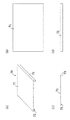
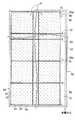
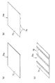
以下、本発明について緑化設備の実施例に基づき説明する。図1〜図4は第1実施例の緑化設備に関し、図1は仕切材を示す図、図2はカバー材を示す図、図3及び図4は仕切構造を形成した状態を示す図である。 Hereinafter, this invention is demonstrated based on the Example of a greening installation. 1 to 4 relate to the greening facility of the first embodiment, FIG. 1 is a view showing a partition member, FIG. 2 is a view showing a cover member, and FIGS. 3 and 4 are views showing a state in which a partition structure is formed. .
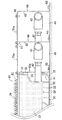
先ず、第1実施例の緑化設備に於ける緑化ユニット10及び緑化エリアについて説明する。第1実施例に於ける緑化ユニット10は底面吸水型であり、図3及び図4に示すように、側壁21と底面22とを有する上面開放の略箱形である植栽部20と、植栽部20の下方に設けられ、側壁31と底面32とを有する上面開放の貯水部30とで構成される。
First, the
植栽部20は、その側壁21に内向きへこみ部23が形成されている。隣接する植栽部20・20の内向きへこみ部23・23相互間で、且つ貯水部30の側壁31の上方位置に空間41が形成され、空間41に多孔質の給水管42或いは配線等を配設可能であり、空間41に給水管42や配線を配設して優れた美観を確保することができる。
The planting
植栽部20の側壁21の隣り合う2辺には、側壁21の略中央上端付近に外方へ突出する略鉤形等の突出片が形成され、側壁21の他の隣り合う2辺には、側壁21の略中央上端付近に凹部が形成されており、植栽部20の突出片を隣り合う植栽部20の凹部へ係合して、隣り合う植栽部20・20相互が連係されている(図示せず)。植栽部20の底面22には、余剰水を配水可能で、且つ植物の根に空気を与えるための通水兼通気孔が複数穿設され(図示せず)、又、底面22には、中空で下端頂面に吸水孔25が穿設された吸水凸部24が下方に突出して4つ形成されていると共に、底面下方へ吸水凸部24よりも僅かに長く突出した脚部26が形成されている。
On the two adjacent sides of the
植栽部20には育成材27が充填され、例えば種子を蒔く・切芝を敷設する・植栽マットを敷設する・植物の苗を施す等により、植物28が植栽される。育成材27には、植物28を栽培可能な適宜のものを用いることが可能であり、例えばパーライト、バーミキュウライト、ピートモス、バーク堆肥、チャフコン、木質腐朽有機物、ゼオライト、下水や浄水場から発生する汚泥、或いは汚泥の焼却灰等とすることができ、又、これらの内の数種類を選定し、必要に応じて根腐れ防止用の珪酸塩白土等を植物の種類、環境等に応じて適宜選定し、これらを保水性、排水性を良好にするためにバランス良く配合したもの、又、これらを単体で若しくは配合して固化しブロック状にした軽量育成材や、スポンジやヤシガラ繊維、不織布等の繊維材等の軽量育成材等としてもよい。前記通気性良好な軽量育成材を育成材27として採用することにより、植物28の根が傷むことを防止することができ、又、これらの軽量育成材の重量は客土の約1/3以下であることから、敷設面への荷重負荷を軽減することが可能である。
The
また、貯水部30は、低い側壁31を有するトレー状であり、側壁31の四辺には側壁上端に外方に突出する鉤形連係部が形成されており、一方の隣り合う2辺には突出する幅が広い幅広連係部33が形成され、他の隣り合う2辺には突出する幅が狭い幅狭連係部34が形成されている。貯水部30の幅狭連係部34を覆うように隣の貯水部30の幅広連係部33を上方から係合することにより、隣り合う貯水部30・30相互を連係可能である。
Moreover, the
上記植栽部20は貯水部30の底面32に脚部26を配置して貯水部30に載置される。植栽部20を貯水部30に載置した状態では、吸水凸部24の下端頂面と貯水部底面32との間に隙間が形成され、吸水孔25から良好な吸水を行うことが可能になっている。尚、貯水部側壁31の上端或いは連係部33、34に切欠を設ける、又は貯水部側壁31の高さを低くする等により、貯水部30の最大貯水時の水位を植栽部底面22より下方に位置させる構成とすると、植栽部底面22と貯水部30に貯水される水との間に空気層を常時確保し、新鮮な空気を植物28の根へ与えることが可能になって好適である。
The
更に、上記植栽部20と貯水部30とで構成される緑化ユニット10を、貯水部30の連係部33、34を係合し且つ植栽部20の上記突出片と凹部を係合しながら連係して、建築物の屋上・屋根・ベランダ・テラス等の敷設面に複数並べて敷設すると共に、空間41の貯水部30・30の隣接する側壁31・31の上方位置等に多孔質の給水管42を配設し、給水管42を中心に両側の貯水部30・30に水分や養分等を供給可能にして、緑化エリアを構成する。尚、前記給水管42は、各緑化ユニット10の貯水部30に直接給水可能に配設する以外に、例えば敷設面の勾配に応じて上流側に少なくとも1つ以上配設し、貯水部30の側壁31上端やその上端に形成された凹部等をオーバーフローさせて全貯水部30に給水する構成等としてもよい。
Further, the
そして、上記緑化エリアと非緑化エリアとを仕切る仕切構造が緑化エリアの周縁に配設される。前記仕切構造は図1に示す仕切材50を有し、仕切材50は、略水平に設けられる押圧片51と、押圧片51の外端縁を下方に屈曲して垂下延設されている側壁52と、側壁52の下端縁を外方に屈曲して水平に延設されている固定片53とで構成される柱状であり、断面視略Z字形に形成されている。
And the partition structure which partitions off the said greening area and a non-greening area is arrange | positioned at the periphery of a greening area. The partition structure includes a
仕切材50は、緑化ユニット10の敷設面・敷設箇所或いは仕切材50の設置箇所に、固定片53がボルト、アンカーボルト、接着剤等の固定手段で固定され、前記固定状態で、押圧片51の下面により、緑化エリアの周縁に設けられる植栽部20の一部、例えば植栽部側壁21の上端、植栽部20に充填された育成材27若しくはそこに植栽された植物28の緑化エリア周縁近傍、或いはこれらの複数箇所を押圧する構成であり、固定片53の下面から押圧片51の下面までの高さは、押圧前は、敷設された緑化ユニット10の上端部よりも僅かに低く形成されており、固定片53を設置箇所に固定することにより、押圧片51で緑化ユニット10を押圧する構成となっている。緑化エリアの周縁で、配管或いは配線等を配設しない仕切箇所には、上記仕切材50を配設するのみで仕切構造が完成する。
The
尚、植栽部20の押圧される上端箇所が弾性を有する植栽マットや切芝である場合に、柔軟性を持って押圧することが可能になって好適であり、又、押圧片51の押圧面にシート状等のゴム材など弾性材を設ける構成、又は、仕切材50若しくは押圧片51を弾性樹脂材など弾性材で形成することも可能である。
In addition, when the upper end location where the
他方で、配管或いは配線等を配設する場合には、緑化エリアの周縁に於ける植栽部20の隅部或いは植栽部20の隅部の集合箇所の一部等で、且つ給水管42等が緑化エリアに引き込まれて配設されていない箇所に、短めの仕切材50aを配設し、仕切材50aから配管や配線の設置スペースに応じた所定距離だけ外方に離間した位置に、同一部材など仕切材50と同一形状の外壁材60を配設する。尚、仕切材50aは、少なくとも植栽部20の隅部で植栽部20を押圧可能であればよく、前記短めの仕切材50とする以外に、例えば植栽部20の側壁21全体に沿って植栽部20を押圧する構成等としてもよい。又、前記外壁材60を配設する所定距離は、配管や配線の太さや量など必要とする設置スペースに応じて変更可能である。
On the other hand, in the case of arranging piping or wiring, etc., at the corner of the
更に、緑化エリアの周縁に於ける植栽部20の周縁の一部箇所に仕切材50aを配設し、仕切材50aから所定距離離して外壁材60を配設することにより、仕切材50aと外壁材60との間の空間40、即ち、仕切材50aの側壁52の外面と、外壁材60の側壁62の内面と、敷設面等とで構成される空間40に、例えば給水本管43を配設し、給水本管43から分岐して給水管42を空間41内に導入するなど、配管或いはセンサーや電力等の配線を設置し、仕切材50aと外壁材60との間に上方からカバー材70を架橋して被せる。前記カバー材70には、図2に示すように、カバー板71の内端に仕切材50aの押圧片51の内端縁に係止可能なフック部72が下方へ屈曲して形成され、カバー板71の外端に外壁材60の側壁62上端を覆いながら係止する屈曲片73が下方へ屈曲して形成されており、カバー材70は外壁材60の側壁62上端部分(押圧片61)に、ビス、リベット、両面テープ、接着剤等の固定手段で固定して設けられ、仕切構造が完成する。
Furthermore, the
尚、出隅、入隅の処理は、図3に示すように、仕切材50のみの仕切構造の場合に於ける仕切材50の隅部を、突合箇所の長さが合うように45度など所定角度にカットし、突き合わせることで処理する。また、配管などが配設される仕切材50a、外壁材60、カバー材70で構成される仕切構造と、仕切材50とを突合する場合には、前記仕切構造の幅に応じて突合箇所の長さが合うように、仕切材50a、外壁材60、カバー材70と仕切材50を所定角度にカットし、突き合わせることで処理する。
In addition, as shown in FIG. 3, the corners of the
上記第1実施例の緑化設備、或いはその仕切構造、仕切材50、50aを使用することにより、緑化エリアの最も風などの影響を受けやすい外周近傍を仕切材50、50aの押圧片51で上方から押圧することができるため、風などで緑化ユニット10等が飛散することを防止することができる。特に、緑化エリアの外周以外の内部は風の影響を受けにくいことに加え、第1実施例では、植栽部20・20の側壁21・21相互間が上記突出部と凹部の係合で連係され、貯水部30・30の側壁31・31相互間が連係部33、34の係合で連係されるため、風などの影響で飛散する可能性は極めて低い。また、例えば植物28として芝生等の匍匐植物を植栽する構成によっても、植栽部20・20を隣り合う側壁21・21の上端近傍で芝生のランナー等で連結することができるため、風などの影響で飛散する可能性を低下することができる。換言すれば、仕切箇所で押圧片53を有する仕切材50、50aなど仕切構造を敷設面と固定状態とすることにより、緑化エリア全体を敷設面や敷設箇所に略固定状態とし、安定して定着させることができる。
By using the greening facility of the first embodiment, or its partition structure, and the
また、仕切材50aと外壁材60と敷設箇所或いは敷設面とカバー材70とで空間を形成する仕切構造とすることにより、配管或いは配線用の空間を確保することができ、美観に優れた緑化エリアを形成することが可能となる。更に、カバー材70の幅を変更して空間の幅や広さを簡単に調整することができるので、収納すべき配管や配線の量やその配設構造の多様性に容易且つ安価に適応することが可能である。更に、外壁材60を仕切材50、50aと同一部材とする場合には、別途異なる部材を製造、準備する必要がなくなるため、コストダウンを図ることができる。
In addition, by using a partition structure in which a space is formed by the
以上、第1実施例の緑化設備、及びその仕切構造、仕切材50、50a等について説明したが、本発明に於ける緑化設備、仕切構造、その仕切材、カバー材、外壁材等の構成や形状は上記第1実施例に限定されるものではなく、例えば以下のような様々な拡張や変形が可能である。
As described above, the greening equipment of the first embodiment, and its partition structure,
緑化ユニット10、植栽部20、貯水部30は第1実施例に於ける構成以外にも適宜であり、又、緑化ユニットはユニット体であれば適宜であり、例えば植栽部20のみの緑化ユニット、貯水部30の側壁31の上端に植栽部20の脚部26を配置して貯水部30の貯水容量を大きくした緑化ユニット等とすることが可能である。更に、植栽部20は箱体に育成材27を充填する構成以外に、例えば固化した育成材27のみで構成される植栽部20、繊維材の育成材27のみで構成される植栽部20等とすることが可能である。更に、植栽部20は一つの凹部が形成された一体的な箱体とする構成以外に、例えば複数の箱体を連結リブで連結し、一ユニットに対応して複数の凹部が設けられた植栽部20、或いは複数の凹部が形成された一体的な箱体の植栽部20等とすることが可能である。更に、貯水部30と植栽部20とを1対1で対応する構成以外に、例えば一つの植栽部20に対応して複数の貯水部30を設ける、或いは複数の植栽部20に対応して一つの貯水部30を設ける、或いは1対1で対応させずに3個の植栽部20を2個の貯水部30に対応させる等、複数の植栽部20を複数の貯水部30に対応して設ける構成等とすることが可能である。
The
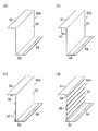
また、仕切材50、50aの形状は第1実施例に於ける形状に限定されるものではなく、例えば図5に示す形状としてもよい。図5(a)の仕切材50bは、仕切材50と同様に押圧片51、側壁52、固定片53を備えると共に、固定片53に凹溝54が形成され、敷設面に固定するアンカー等を打つ際の穴開け加工時に凹溝54で穴あけの位置を決定し、幅方向の位置ズレを防止して確実に所定箇所に固定することが可能な構成である。図5(b)の仕切材50cは、仕切材50と同様に押圧片51、側壁52、固定片53を備えると共に、凹溝54が形成され、更に、押圧片51と側壁52との間に中空筒形の補強部55が設けられ、押圧片51による押圧時に押圧片51が上方へ屈曲する、或いは上方へ大きく屈曲することを防止する構成である。図5(c)の仕切材50dは、仕切材50と同様に押圧片51、側壁52、固定片53を備えると共に、凹溝54が形成され、更に、押圧片51の下面に補強用の突条56、側壁52の内面に補強用の複数の突条57が設けられ、側壁52の最下端の突条57は固定片53を内側へそのまま延設したものとする。前記構成により、固定片53の安定性が高められると共に、側壁52、押圧片51の強度を増加することができる。図5(d)の仕切材50eは、仕切材50と同様に押圧片51、側壁52、固定片53を備えると共に、凹溝54が形成され、更に、側壁52の外方に僅かに突出する複数の突条58が設けられ、側壁52から押圧片51に至る屈曲部59が肉厚に形成され、又、側壁52の最下端で固定片53を内側へそのまま延設して突条57としているものである。前記構成により、押圧片51による押圧時に押圧片51が上方へ屈曲されることを防止することができると共に、側壁52の強度を増加することができ、更には、デザイン性に優れた仕切材50eを構成することが可能となる。尚、仕切構造として用いる仕切材50等には、上記構成の仕切材50等を単独で用いる、又は組み合わせて用いることが可能である。また、これらの仕切材50〜50eは樹脂等を素材として押出成形などで成形することが可能であり、安価に製造することができる。
Moreover, the shape of the
また、カバー材70の形状も第1実施例に於ける形状に限定されるものではなく、例えば図6に示す形状としてもよい。図6(a)のカバー材70aは、フック部72と屈曲片73を有しないカバー板71だけからなるものであり、製造コストを大幅に低減可能な構成である。尚、カバー板71にフック部72又は屈曲片73の何れか一方のみを設ける構成としてもよい。図6(b)のカバー材70bは、カバー板71の下面に補強用の複数の突条74が形成され、強度を高められるようになっている。図6(c)のカバー材70cは、カバー板71の上面に若干幅広の突条75が形成されている。前記突条75により、補強して強度を高められると共に、飾り等として用いることでデザイン性を向上することができる。尚、仕切構造として用いるカバー材70等には、上記構成のカバー材70等を単独で用いる、又は組み合わせて用いることが可能である。また、これらのカバー材70〜70cは、樹脂等を素材とする押出成形或いは曲げ加工などで成形することが可能であり、安価に製造することができる。
Further, the shape of the
また、予め配管や配線の量や構造を認識し、その量や構造に応じたカバー材70等を製造して用いる構成、或いは幅広のカバー材70a〜70c等を準備し、現場で必要に応じて切断して幅を調整する構成とする以外に、例えば図7に示すように、仕切材50aを固設し、仕切材50aから所定距離離して仕切材50aと同一形状或いは長さのみ異なる中間仕切材80をアンカー等で固定して設け、中間仕切材80から所定距離離して外壁材60を固定して設け、仕切材50aと中間仕切材80との間、中間仕切材80と外壁材60との間に、それぞれ給水本管43等を配設すると共に、仕切材50aと中間仕切材80との間にカバー材70a等を架橋して仕切材50aの押圧片51の上面と中間仕切材80の押圧片81の上面にボルト締め等で固設し、中間仕切材80と外壁材60との間にカバー材70a等を架橋して中間仕切材80の押圧片81の上面と外壁材60の押圧片61の上面にボルト締め等で固設する構成としてもよく、更には、仕切材50aと中間仕切材80との間の距離と、中間仕切材80と外壁材60との間の距離を同一とし、同一幅のカバー材70を並設する構成等としてもよい。前記構成により、配管や配線の量や構造に応じて柔軟に仕切構造内の空間量を調整することが可能であると共に、仕切構造の構成部材の種類を減らし、在庫管理の労力や製造コストを低減することができる。更に、中間仕切材80の存在により、カバー材70aの上方からの踏圧などの力に対して強度が増し、カバー材70aを薄く形成することができ、コストダウンに繋がる。
Also, the amount and structure of piping and wiring are recognized in advance, and a structure for manufacturing and using the
尚、図7の構成では、一番内側の仕切材50aは給水本管43から緑化エリア内に導入される給水管42が横切らない箇所に配設され、中間仕切材80も同様に給水管42が横切らない箇所に配設され、外壁材60は外周側面を全て覆うように配設されるようになっており、例えば外側の給水本管43と内側の給水本管43の両方から給水管43が導入される箇所に配設される仕切材50aは、仕切材50a相互間等に給水管42の導入に必要な隙間を形成するために、長さが短く形成され、必要に応じて数多く配設され、外側の給水本管43から給水管42が導入される箇所に配設される中間仕切材80は、仕切材50aより長さが長く形成され、必要に応じて仕切材50aより数少なく配設される。
In the configuration of FIG. 7, the
また、仕切材50等、外壁材60、カバー材70等は別体として構成する以外に、全て或いは一部を一体化した部材を用いてもよく、例えば仕切材50等とカバー材70等を一体形成、或いはカバー材70等と外壁材60を一体形成、或いは仕切材50等と外壁材60とカバー材70等を一体形成した部材を用いることが可能である。
In addition, the
また、上記仕切材50等、外壁材60、中間仕切材80の固定片53、63、83は、施工性の考慮から外方に屈曲して延設する構成としたが、例えば意匠上の配慮から、固定片53、63、83、特に外壁材60の固定片63を内方へ屈曲して延設し、断面コ字形の仕切材50等、外壁材60、中間仕切材80としてもよく、前記構成により、仕切構造や緑化設備の美観を高められる。
Further, the fixing
また、板状のカバー材70等とする他に、例えば仕切材50等と外壁材60との間に配線或いは配管を施し、それらの上からカバー材として砂利等を充填して被覆するようにすることも可能であり、前記構成により、緑化設備やその仕切構造の優れた美観が得られる。尚、カバー材として、砂利等の他に、木材、石材、ゴム板、ゴムチップ等を充填或いは敷設することも可能であり、又、配管や配線と敷設面との間に、発泡材等の下地材を配設してから、前記のようなカバー材で覆う構成としてもよい。
In addition to the plate-
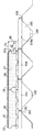
また、緑化エリアの仕切構造は、例えば図8及び図9に示す山部101と谷部102が交互に連設される折板屋根100など、下方から風等の影響を受けやすい箇所に緑化エリアを形成する場合に用いると一層有効である。尚、超高層ビルの屋上やベランダなど風の強い場所でも同様に有効性が高い。
The partitioning structure of the greening area is, for example, a greening area in a place that is easily affected by wind or the like from below, such as a folded-
図8、図9の第2実施例の緑化設備に関し、ハゼタイプの折板屋根100には、山部101・101相互間にハゼ103の頂部よりも上面が高くなる下地の棒材104が架橋される。棒材104は、断面コ字形のチャンネル部材であり、山部101・101の頂面に下方が開口するように配設されて接着剤や両面テープ等で固定される。前記棒材104の構成により、材料費や製造費を低減することが可能になると共に、後述する仕切構造との固定も容易となる。また、緑化エリアの周縁に位置する最外端の棒材104aには、折板屋根100の谷部102の形状に合う略台形のカバー部105が一体で形成され或いは別体で設けられ、カバー部105で風の進入を防止することが可能であると共に、カバー部105の最下部と谷部102の最下部との間に開口106が形成され、開口106から排水可能になっている。そして、固定された棒材104、104a上に緑化ユニット10が配設され緑化エリアが構成されると共に、緑化エリアの周縁に仕切材50、50a、外壁材60、カバー材70等で構成される仕切構造が設けられ、仕切材50、50a、外壁材60は適宜箇所の棒材104、104aにビスなどで固定される。前記緑化エリアは、排水の必要性から開口106を設けることが不可欠となるが、開口106から進入する風で緑化ユニット10に風力が負荷されても、前記仕切構造により、飛散を防止することができる。
8 and FIG. 9, regarding the greening facility in the second embodiment of FIG. 8, the
また、緑化エリアの仕切構造を、仕切構造の端部相互を隣接して突き合わせる構成以外に、例えば仕切構造の端部相互を離間して集合させるようにして配設してもよい。更に、仕切構造の端部相互の突き合わせ箇所や集合箇所では、例えば仕切構造の端部相互を接続板を介して接続する構成や、或いはカバー材で被覆する構成等とすることが可能である。 Further, the partitioning structure of the greening area may be arranged so as to collect the end portions of the partitioning structure apart from each other, for example, in addition to the configuration in which the end portions of the partitioning structure are adjacently butted. Further, at the locations where the ends of the partition structure are abutted or gathered, for example, the ends of the partition structure can be connected to each other via a connection plate, or can be configured to be covered with a cover material.
本発明は、例えば建築物の屋上、屋根、ベランダ等に緑化ユニットを敷設して緑化エリアを形成する際に、緑化エリアと非緑化エリアとを仕切る場合に利用することができる。 The present invention can be used for partitioning a greening area and a non-greening area when a greening area is formed by laying a greening unit on a rooftop, roof, veranda or the like of a building, for example.
10 緑化ユニット
20 植栽部
30 貯水部
21、31 側壁
22、32 底面
23 内向きへこみ部
27 育成材
28 植物
33、34 連係部
40、41 空間
42 給水管
43 給水本管
50、50a、50b、50c、50d、50e 仕切材
60 外壁材
80 中間仕切材
51、61、81 押圧片
52、62、82 側壁
53、63、83 固定片
60 外壁材
70、70a、70b、70c カバー材
71 カバー板
72 フック部
73 屈曲片
100 折板屋根
103 ハゼ
104、104a 棒材
105 カバー部
106 開口
DESCRIPTION OF
Claims (7)
Priority Applications (1)
| Application Number | Priority Date | Filing Date | Title |
|---|---|---|---|
| JP2005070461A JP2006246830A (en) | 2005-03-14 | 2005-03-14 | Partitioning material of tree-planting area, partitioning structure and tree-planting facility |
Applications Claiming Priority (1)
| Application Number | Priority Date | Filing Date | Title |
|---|---|---|---|
| JP2005070461A JP2006246830A (en) | 2005-03-14 | 2005-03-14 | Partitioning material of tree-planting area, partitioning structure and tree-planting facility |
Publications (1)
| Publication Number | Publication Date |
|---|---|
| JP2006246830A true JP2006246830A (en) | 2006-09-21 |
Family
ID=37087939
Family Applications (1)
| Application Number | Title | Priority Date | Filing Date |
|---|---|---|---|
| JP2005070461A Pending JP2006246830A (en) | 2005-03-14 | 2005-03-14 | Partitioning material of tree-planting area, partitioning structure and tree-planting facility |
Country Status (1)
| Country | Link |
|---|---|
| JP (1) | JP2006246830A (en) |
Cited By (3)
| Publication number | Priority date | Publication date | Assignee | Title |
|---|---|---|---|---|
| WO2007063660A1 (en) * | 2005-12-02 | 2007-06-07 | Kyodo Ky-Tec Corp. | Partition structure of greening facility |
| JP2010138545A (en) * | 2008-12-09 | 2010-06-24 | Sekisui Plastics Co Ltd | Roof seeding and planting structure |
| JP2016011519A (en) * | 2014-06-28 | 2016-01-21 | 株式会社トーケン | Installation hardware and installation structure of greening base material |
Citations (6)
| Publication number | Priority date | Publication date | Assignee | Title |
|---|---|---|---|---|
| JPH1175562A (en) * | 1997-09-01 | 1999-03-23 | C I Kasei Co Ltd | Plant culture device and its outer frame structure |
| JPH1175568A (en) * | 1997-08-29 | 1999-03-23 | Kyodo Ky Tec Kk | Planting mat and method for laying same |
| JP2000324953A (en) * | 1999-05-17 | 2000-11-28 | Daiwa House Ind Co Ltd | Greening system for sloped roof |
| JP2003339241A (en) * | 2002-05-23 | 2003-12-02 | Shimizu Corp | Greening system for slanting corrugated roof |
| JP2004236669A (en) * | 1998-10-20 | 2004-08-26 | Kyodo Ky Tec Corp | Structure for treating border in plant growing area |
| JP2004290152A (en) * | 2003-03-28 | 2004-10-21 | Kyodo Ky Tec Corp | Border structure of greening area |
-
2005
- 2005-03-14 JP JP2005070461A patent/JP2006246830A/en active Pending
Patent Citations (6)
| Publication number | Priority date | Publication date | Assignee | Title |
|---|---|---|---|---|
| JPH1175568A (en) * | 1997-08-29 | 1999-03-23 | Kyodo Ky Tec Kk | Planting mat and method for laying same |
| JPH1175562A (en) * | 1997-09-01 | 1999-03-23 | C I Kasei Co Ltd | Plant culture device and its outer frame structure |
| JP2004236669A (en) * | 1998-10-20 | 2004-08-26 | Kyodo Ky Tec Corp | Structure for treating border in plant growing area |
| JP2000324953A (en) * | 1999-05-17 | 2000-11-28 | Daiwa House Ind Co Ltd | Greening system for sloped roof |
| JP2003339241A (en) * | 2002-05-23 | 2003-12-02 | Shimizu Corp | Greening system for slanting corrugated roof |
| JP2004290152A (en) * | 2003-03-28 | 2004-10-21 | Kyodo Ky Tec Corp | Border structure of greening area |
Cited By (4)
| Publication number | Priority date | Publication date | Assignee | Title |
|---|---|---|---|---|
| WO2007063660A1 (en) * | 2005-12-02 | 2007-06-07 | Kyodo Ky-Tec Corp. | Partition structure of greening facility |
| JP2007151445A (en) * | 2005-12-02 | 2007-06-21 | Kyodo Ky Tec Corp | Partition structure of greening facilities |
| JP2010138545A (en) * | 2008-12-09 | 2010-06-24 | Sekisui Plastics Co Ltd | Roof seeding and planting structure |
| JP2016011519A (en) * | 2014-06-28 | 2016-01-21 | 株式会社トーケン | Installation hardware and installation structure of greening base material |
Similar Documents
| Publication | Publication Date | Title |
|---|---|---|
| KR100676993B1 (en) | Plant cultivation mat and method for laying the same | |
| JP5142498B2 (en) | Planting equipment and planting structure for plants | |
| RU2370020C2 (en) | Construction for greening up wall | |
| EP2331768B1 (en) | Roof with modular plant covering | |
| SG189299A1 (en) | Planting tray | |
| CN109168942A (en) | The support of assembled roof greening plant | |
| EP3945778A1 (en) | Panel-modular layered wall system for shaping spatial structures | |
| WO2007069395A1 (en) | Fixing structure for planting bed | |
| KR100844108B1 (en) | Bending structure for green wall unit and green wall system using the same | |
| JP4593459B2 (en) | Rooftop greening construction panel and rooftop greening construction system using the rooftop greening construction panel | |
| JP2006246830A (en) | Partitioning material of tree-planting area, partitioning structure and tree-planting facility | |
| JP4987294B2 (en) | Planting equipment, planting container and laying method | |
| KR102048147B1 (en) | Folwerpot Modume | |
| JP4589505B2 (en) | Manufacturing method of water retention pad for rooftop greening, water retention pad for rooftop greening, vegetation base and rooftop greening method | |
| JP2005261294A (en) | Method for greening on artificial ground, greening structure and water holding drainage base material used therein | |
| KR100624746B1 (en) | Housetop tree planting system | |
| JP3834015B2 (en) | Rooftop greening equipment | |
| JP4767116B2 (en) | Revegetation structure of the constructed wall with the machin block | |
| KR100830937B1 (en) | Water supply sheet with water supply column | |
| JP5007040B2 (en) | Greening facility partition structure | |
| JP4962895B2 (en) | Origami roof greening structure and greening origami roof | |
| JP4747135B2 (en) | Planting mat and its laying method | |
| JP7154559B2 (en) | Greening area partition structure | |
| WO2023188200A1 (en) | Planting unit | |
| JP5011199B2 (en) | Rooftop greening construction panel and rooftop greening construction system using the rooftop greening construction panel |
Legal Events
| Date | Code | Title | Description |
|---|---|---|---|
| A621 | Written request for application examination |
Free format text: JAPANESE INTERMEDIATE CODE: A621 Effective date: 20080206 |
|
| A977 | Report on retrieval |
Free format text: JAPANESE INTERMEDIATE CODE: A971007 Effective date: 20100402 |
|
| A131 | Notification of reasons for refusal |
Free format text: JAPANESE INTERMEDIATE CODE: A131 Effective date: 20101208 |
|
| A521 | Written amendment |
Free format text: JAPANESE INTERMEDIATE CODE: A523 Effective date: 20110202 |
|
| A02 | Decision of refusal |
Free format text: JAPANESE INTERMEDIATE CODE: A02 Effective date: 20110824 |