JP2006245110A - Heat-treating apparatus - Google Patents
Heat-treating apparatus Download PDFInfo
- Publication number
- JP2006245110A JP2006245110A JP2005055944A JP2005055944A JP2006245110A JP 2006245110 A JP2006245110 A JP 2006245110A JP 2005055944 A JP2005055944 A JP 2005055944A JP 2005055944 A JP2005055944 A JP 2005055944A JP 2006245110 A JP2006245110 A JP 2006245110A
- Authority
- JP
- Japan
- Prior art keywords
- substrate
- heaters
- processing
- thermal processing
- heater
- Prior art date
- Legal status (The legal status is an assumption and is not a legal conclusion. Google has not performed a legal analysis and makes no representation as to the accuracy of the status listed.)
- Pending
Links
Images


Classifications
-
- G—PHYSICS
- G02—OPTICS
- G02F—OPTICAL DEVICES OR ARRANGEMENTS FOR THE CONTROL OF LIGHT BY MODIFICATION OF THE OPTICAL PROPERTIES OF THE MEDIA OF THE ELEMENTS INVOLVED THEREIN; NON-LINEAR OPTICS; FREQUENCY-CHANGING OF LIGHT; OPTICAL LOGIC ELEMENTS; OPTICAL ANALOGUE/DIGITAL CONVERTERS
- G02F1/00—Devices or arrangements for the control of the intensity, colour, phase, polarisation or direction of light arriving from an independent light source, e.g. switching, gating or modulating; Non-linear optics
- G02F1/01—Devices or arrangements for the control of the intensity, colour, phase, polarisation or direction of light arriving from an independent light source, e.g. switching, gating or modulating; Non-linear optics for the control of the intensity, phase, polarisation or colour
- G02F1/13—Devices or arrangements for the control of the intensity, colour, phase, polarisation or direction of light arriving from an independent light source, e.g. switching, gating or modulating; Non-linear optics for the control of the intensity, phase, polarisation or colour based on liquid crystals, e.g. single liquid crystal display cells
- G02F1/1303—Apparatus specially adapted to the manufacture of LCDs
-
- B—PERFORMING OPERATIONS; TRANSPORTING
- B65—CONVEYING; PACKING; STORING; HANDLING THIN OR FILAMENTARY MATERIAL
- B65G—TRANSPORT OR STORAGE DEVICES, e.g. CONVEYORS FOR LOADING OR TIPPING, SHOP CONVEYOR SYSTEMS OR PNEUMATIC TUBE CONVEYORS
- B65G39/00—Rollers, e.g. drive rollers, or arrangements thereof incorporated in roller-ways or other types of mechanical conveyors
- B65G39/10—Arrangements of rollers
- B65G39/12—Arrangements of rollers mounted on framework
- B65G39/18—Arrangements of rollers mounted on framework for guiding loads
-
- C—CHEMISTRY; METALLURGY
- C03—GLASS; MINERAL OR SLAG WOOL
- C03B—MANUFACTURE, SHAPING, OR SUPPLEMENTARY PROCESSES
- C03B27/00—Tempering or quenching glass products
- C03B27/012—Tempering or quenching glass products by heat treatment, e.g. for crystallisation; Heat treatment of glass products before tempering by cooling
-
- C—CHEMISTRY; METALLURGY
- C03—GLASS; MINERAL OR SLAG WOOL
- C03B—MANUFACTURE, SHAPING, OR SUPPLEMENTARY PROCESSES
- C03B27/00—Tempering or quenching glass products
- C03B27/04—Tempering or quenching glass products using gas
Abstract
Description
本発明は、例えば、液晶表示装置(LCD)等のFPD(フラットパネルディスプレイ)の製造プロセスにおけるガラス基板等のフォトリソグラフィー工程において、基板を加熱、冷却するために用いる熱的処理装置に関する。 The present invention relates to a thermal processing apparatus used for heating and cooling a substrate in a photolithography process such as a glass substrate in a manufacturing process of an FPD (flat panel display) such as a liquid crystal display (LCD).
例えば、LCDの製造工程においては、フォトリソグラフィー技術を用いて、ガラス基板にレジスト液を供給して塗布膜を形成し、これを乾燥、熱処理した後に、露光処理、現像処理を逐次行うことにより、ガラス基板に所定の回路パターンを形成している。ここで、ガラス基板にレジスト液を供給して塗布膜を形成した後は、塗布膜を加熱して不要な溶剤等を除去するプリベーク処理が行われている。また、露光処理後には露光によるレジスト膜の化学変化を促進するためのポストエクスポージャーベーク処理が行われ、現像処理後には現像パターンの固定とガラス基板の乾燥を兼ねたポストベーク処理が行われている。 For example, in the LCD manufacturing process, by using a photolithographic technique, a resist solution is supplied to a glass substrate to form a coating film, which is dried and heat treated, and then sequentially subjected to exposure processing and development processing, A predetermined circuit pattern is formed on the glass substrate. Here, after forming the coating film by supplying the resist solution to the glass substrate, a pre-bake process is performed in which the coating film is heated to remove unnecessary solvents and the like. Further, after the exposure process, a post-exposure bake process for promoting chemical change of the resist film due to exposure is performed, and after the development process, a post-bake process that combines fixing of the development pattern and drying of the glass substrate is performed. .
従来、このような熱処理を行う装置としては、ガラス基板を載置するためのホットプレートと、このホットプレート上でガラス基板を昇降させるための昇降機構と、ホットプレートを内包するためのチャンバと、を有する加熱装置が用いられている(例えば、特許文献1参照)。また、加熱処理が終了したガラス基板は、必要に応じて、冷却プレートを備えた冷却装置に搬送されて、そこで冷却処理される。 Conventionally, as an apparatus for performing such heat treatment, a hot plate for placing a glass substrate, a lifting mechanism for lifting and lowering the glass substrate on the hot plate, a chamber for containing the hot plate, (For example, refer patent document 1). In addition, the glass substrate that has been subjected to the heat treatment is transported to a cooling device having a cooling plate as needed, and is subjected to a cooling treatment there.
しかしながら、このような加熱装置および冷却装置では、ガラス基板を装置に搬入出するために時間がかかり、スループットがよいものではない。また、近時、ガラス基板の大型化が急速に進んでいるために、フォトリソグラフィー工程においては、ガラス基板を回転させてレジスト膜を形成する等のスピンナタイプの装置を用いた処理では、ガラス基板の中心と周縁とで処理にむらが生じやすいため、このような装置に代えて、基板を一方向に搬送しながらレジスト液を塗布して塗布膜を形成し、また現像液を塗布して現像する、所謂、搬送タイプの装置が用いられるようになっている。そのため、このような搬送タイプの装置と、従前のバッチ式の加熱装置等を組み合わせて、レジスト膜形成から現像までを一貫して行うシステムを構築すると、基板の搬送システムが複雑となり、またスループットを高めることも困難となる。
本発明はかかる事情に鑑みてなされたものであり、基板を搬送しながら加熱や冷却を行うことができるスループットの高い熱的処理装置であって、さらに基板の加熱むらや冷却むらの発生を抑制することができる熱的処理装置を提供することを目的とする。 The present invention has been made in view of such circumstances, and is a high-throughput thermal processing apparatus that can perform heating and cooling while transporting a substrate, and further suppresses the occurrence of uneven heating and cooling of the substrate. It is an object of the present invention to provide a thermal processing apparatus that can be used.
本発明によれば、基板を略水平姿勢で水平方向に搬送しながら熱的処理する熱的処理装置であって、
基板を水平方向に搬送するための基板搬送機構と、
基板を加熱するために、前記基板搬送機構による基板の搬送ルート上の所定の高さ位置に当該搬送ルートに沿って所定間隔で隙間を設けながら配置された複数のパネル形状のヒータと、
を具備し、
前記ヒータはそれぞれ複数の小ヒータから構成され、前記複数の小ヒータの継ぎ目に起因して基板に転写痕が発生することを防止するために、前記複数の小ヒータはその継ぎ目が一定の距離範囲内において基板搬送方向と平行にならないように連結されていることを特徴とする熱的処理装置、が提供される。
According to the present invention, a thermal processing apparatus that performs thermal processing while conveying a substrate in a horizontal direction in a substantially horizontal posture,
A substrate transport mechanism for transporting the substrate in a horizontal direction;
In order to heat the substrate, a plurality of panel-shaped heaters arranged at predetermined intervals along the transfer route at predetermined height positions on the transfer route of the substrate by the substrate transfer mechanism,
Comprising
Each of the heaters is composed of a plurality of small heaters, and in order to prevent transfer marks from being generated on the substrate due to the joints of the plurality of small heaters, the joints of the plurality of small heaters have a certain distance range. In the thermal processing apparatus, the thermal processing apparatus is connected so as not to be parallel to the substrate transport direction.
本発明に係る熱的処理装置において、各ヒータは大きさの異なる複数種の小ヒータを複数組み合わせて構成されていることが好ましく、これにより小ヒータの継ぎ目を配置する自由度が大きくなる。また、この熱的処理装置に、複数のヒータ間に設けられた隙間へ所定温度に加熱されたガスを供給する加熱ガス供給装置と、複数のヒータ間に設けられた隙間から吸気を行うための吸気装置をさらに設け、加熱ガス供給装置からのガス供給ポイントと、吸気装置からの吸気ポイントを基板搬送方向に沿って存在する複数のヒータ間の隙間に交互に設けると、基板からの蒸発物を効率的に排除することができ、好ましい。 In the thermal processing apparatus according to the present invention, each heater is preferably configured by combining a plurality of types of small heaters having different sizes, thereby increasing the degree of freedom in arranging the joints of the small heaters. In addition, a heating gas supply device that supplies a gas heated to a predetermined temperature to a gap provided between the plurality of heaters, and an intake air from the gap provided between the plurality of heaters. If an intake device is further provided, and the gas supply point from the heated gas supply device and the intake point from the intake device are alternately provided in the gaps between the plurality of heaters along the substrate transport direction, the evaporated material from the substrate is removed. This is preferable because it can be eliminated efficiently.
基板搬送機構として、基板搬送方向に垂直な方向を長軸方向として基板搬送方向に所定間隔で並べられた複数の円柱状のローラー部材と、これらのローラー部材を回転させるためのローラー駆動手段を有するものを用い、さらに熱的処理装置に基板搬送機構によって搬送される基板の裏面から基板を加熱するためのIRヒータまたは熱放射能を有するランプを設けて、IRヒータまたはランプは基板を直接加熱するだけでなくローラー部材を加熱して、ローラー部材から基板への熱伝達によっても基板を加熱する構成とすると、スループットを向上させることができ、好ましい。このため、ローラー部材には蓄熱性材料が好適に用いられる。 The substrate transport mechanism includes a plurality of cylindrical roller members arranged at predetermined intervals in the substrate transport direction with a direction perpendicular to the substrate transport direction as a major axis direction, and roller driving means for rotating these roller members. Further, an IR heater or a lamp having thermal radiation for heating the substrate from the back surface of the substrate transported by the substrate transport mechanism is provided in the thermal processing apparatus, and the IR heater or lamp directly heats the substrate. In addition to heating the roller member and heating the substrate by heat transfer from the roller member to the substrate, the throughput can be improved, which is preferable. For this reason, a heat storage material is used suitably for a roller member.
熱的処理装置には、ヒータにより加熱された基板を冷却するために、基板の搬送ルート上の所定の高さ位置に冷却板を設けることができる。その場合、基板の裏面から基板を冷却するために基板の裏面に冷却ガスを吹き付けるための冷却ガス噴射装置を設けることが好ましい。冷却ガスの雰囲気にさらされることによって冷却されるローラー部材には、熱伝導性の高い材料が好適に用いられる。 In the thermal processing apparatus, a cooling plate can be provided at a predetermined height position on the substrate transport route in order to cool the substrate heated by the heater. In that case, it is preferable to provide a cooling gas injection device for spraying a cooling gas to the back surface of the substrate in order to cool the substrate from the back surface of the substrate. A material having high thermal conductivity is suitably used for the roller member that is cooled by being exposed to the atmosphere of the cooling gas.
ヒータを複数の小ヒータから構成すると、個々の小ヒータの温度を調整することによりを加熱均一性を高めることができ、しかも小ヒータの継ぎ目を基板の搬送方向に延在しないように小ヒータを配置することで、処理むらの発生を防止することができる。また、ガラス基板の大きさに適応させたサイズのヒータを作製することが容易であり、さらにヒータコストを低減することができる。基板の上側にパネル状のヒータを配置しても、基板から蒸発する物質を加熱ガスにより効率的に除去することができるので、基板の再汚染を抑制することができる。基板をヒータによってその上面から加熱することに加えて、裏面からも加熱することにより、スループットを向上させることができる。 If the heater is composed of a plurality of small heaters, the uniformity of heating can be improved by adjusting the temperature of each small heater, and the small heaters can be connected so that the seams of the small heaters do not extend in the substrate transport direction. By arranging, it is possible to prevent the occurrence of processing unevenness. Further, it is easy to produce a heater having a size adapted to the size of the glass substrate, and further, the heater cost can be reduced. Even if a panel-like heater is disposed on the upper side of the substrate, the substance evaporating from the substrate can be efficiently removed by the heated gas, so that recontamination of the substrate can be suppressed. In addition to heating the substrate from its upper surface with a heater, the substrate can also be heated from the back surface, thereby improving the throughput.
以下、本発明の実施の形態について添付図面を参照して詳細に説明する。
図1は本発明の第1の実施形態に係るLCDガラス基板(以下「基板」という)Gのレジスト塗布・現像処理システム100の外観を示す斜視図であり、図2(a)はレジスト塗布・現像処理システム100の上段の構成を示す平面図であり、図2(b)はその下段の構成を示す平面図である。
Hereinafter, embodiments of the present invention will be described in detail with reference to the accompanying drawings.
FIG. 1 is a perspective view showing an appearance of a resist coating / developing
レジスト塗布・現像処理システム100は、複数の基板Gを収容するカセットCを載置する容器搬入出部(カセットステーション)6と、基板Gに所定の熱的処理または液処理を施す複数のゾーンが設けられた第1処理部1および第2処理部2と、図示しない露光装置との間で基板Gの受け渡しを行うためのインターフェース部5と、第1処理部1と容器搬入出部6との間に設けられた第1搬送部3と、第1処理部1と第2処理部2との間に設けられた第2搬送部4と、を有している。なお、図1に示されるように、レジスト塗布・現像処理システム100の長手方向をX方向、水平面においてX方向と直交する方向をY方向、鉛直方向をZ方向とする。
The resist coating /
第1処理部1は、上下方向(Z方向)に2段に仕切られた積層構造を有しており、かつ上段と下段がそれぞれY方向にも2つに仕切られている。こうして、第1処理部1の下段には独立した処理ブロック11a・11bが、その上段には処理ブロック11c・11dがそれぞれ形成されている。第2処理部2も同様に上下方向(Z方向)に2段に仕切られ、また、上段と下段がそれぞれY方向にも2つに仕切られており、その下段に独立した処理ブロック12a・12bが、その上段に処理ブロック12c・12dがそれぞれ形成されている。
The
容器搬入出部6はカセットCを載置するステージ7を有しており、例えば、4個のカセットCを所定位置に載置することができるようになっている。容器搬入出部6には、外部からレジスト塗布・現像処理システム100において処理すべき基板Gが収納されたカセットCが搬入され、また、レジスト塗布・現像処理システム100において所定の処理が終了した基板Gが収納されたカセットCが次工程へと搬送される。このようなカセットCの搬入出は、手動搬送またはコンベア等を用いた自動搬送のいずれの形態を用いても構わない。
The container carry-in / out section 6 has a
第1処理部1と容器搬入出部6との間に設けられた第1搬送部3には第1搬送装置17が配設されている。この第1搬送装置17はX方向に伸縮する搬送アーム17aを有しており、搬送アーム17aは、Y方向にスライド自在であり、また水平面内で回転自在であり、さらにZ方向に昇降自在に構成されている。このような構成により第1搬送装置17は、容器搬入出部6と第1処理部1にアクセスして、容器搬入出部6と第1処理部1にとの間で基板Gの受け渡しを行い、また、第1処理部1を構成する処理ブロック11a〜11d間での基板Gの受け渡しを行う。
A
第1処理部1と第2処理部2との間に設けられた第2搬送部4には、搬送アーム18aを有する第2搬送装置18が配設されている。この第2搬送装置18は第1搬送装置17と同様の構造を有しており、第1処理部1と第2処理部2との間での基板Gの受け渡しと、第1処理部1を構成する処理ブロック11a〜11d間での基板Gの受け渡しと、第2処理部2を構成する処理ブロック12a〜12d間での基板Gの受け渡しを行う。
A
インターフェース部5には、第1搬送装置17と同様の構造を有する第3搬送装置19が配設されており、第3搬送装置19の搬送アーム19aは、第2処理部2を構成する処理ブロック12a〜12dにアクセスし、また、第2処理部2との間にインターフェース部5を挟むように配設された図示しない露光装置にアクセスすることができるようになっている。こうして第3搬送装置19は、第2処理部2を構成する処理ブロック12a〜12d間での基板Gの受け渡しを行い、また、第2処理部2と露光装置との間で基板Gの受け渡しを行う。
The
第1処理部1を構成する処理ブロック11aには、第1搬送部3側にスクラバ洗浄に先立って基板Gの有機物を除去するためのエキシマUV照射ゾーン(e−UV)21が設けられ、このエキシマUV照射ゾーン(e−UV)21に隣接して基板Gのスクラバ洗浄処理を行うスクラバ洗浄ゾーン(SCR)22が第2搬送部4側に設けられている。この処理ブロック11a内においては、基板Gは回転処理されることなく、コロ搬送等の方法を用いてX方向に略水平に搬送されつつ、エキシマUV照射処理とスクラバ洗浄処理が連続して行われる。
The
エキシマUV照射ゾーン(e−UV)21とスクラバ洗浄ゾーン(SCR)22の天井部には図示しないフィルターファンユニット(FFU)が設けられている。また、基板Gのスクラバ洗浄処理中に発生する処理液のミスト等がスクラバ洗浄ゾーン(SCR)22からエキシマUV照射ゾーン(e−UV)21へ飛散しないように、スクラバ洗浄ゾーン(SCR)22とエキシマUV照射ゾーン(e−UV)21との間にはシャッターを設けることが好ましい。また、フィルターファンユニット(FFU)からのダウンフローの向きを調節することによってもミスト等の飛散を抑制することができる。 A filter fan unit (FFU) (not shown) is provided on the ceiling of the excimer UV irradiation zone (e-UV) 21 and the scrubber cleaning zone (SCR) 22. In addition, the scrubber cleaning zone (SCR) 22 and the mist of the processing liquid generated during the scrubber cleaning processing of the substrate G are not scattered from the scrubber cleaning zone (SCR) 22 to the excimer UV irradiation zone (e-UV) 21. A shutter is preferably provided between the excimer UV irradiation zone (e-UV) 21. Moreover, scattering of mist etc. can be suppressed also by adjusting the direction of the downflow from a filter fan unit (FFU).
処理ブロック11aのY方向側に仕切壁を隔てて位置する処理ブロック11bには、第1搬送部3側から第2搬送部4側に向かって、クーリングユニット(COL)23、レジスト塗布ユニット(CT)24、減圧乾燥/周縁レジスト除去ユニット(VD/ER)25が並べて配置されており、処理ブロック11bの天井部には図示しないフィルターファンユニット(FFU)が配設されている。
The
クーリングユニット(COL)23においては、基板Gに形成するレジスト膜の均一性を高めるために、レジスト塗布前に基板Gの温度均一性を高める熱的処理が行われる。レジスト塗布ユニット(CT)24では、例えば、帯状にレジスト液を吐出するノズルの下を基板Gを略水平姿勢で通過させることにより、基板Gの表面にレジスト膜が形成される。減圧乾燥/周縁レジストユニット(VD/ER)25は、基板Gに形成されたレジスト膜を熱処理によらずに減圧処理することによりレジスト膜に含まれる揮発成分を蒸発させ、また、レジスト塗布ユニット(CT)24におけるレジスト膜の塗布の際に基板Gの裏面に付着したレジストおよび基板Gの周縁部分のレジスト膜を除去する。クーリングユニット(COL)23からレジスト塗布ユニット(CT)24への基板Gの搬送と、レジスト塗布ユニット(CT)24から減圧乾燥/周縁レジスト除去ユニット(VD/ER)25に向けての基板Gの搬送は、例えば、図示しない基板搬送アームを配設して行うことができる。 In the cooling unit (COL) 23, in order to increase the uniformity of the resist film formed on the substrate G, a thermal process is performed to increase the temperature uniformity of the substrate G before applying the resist. In the resist coating unit (CT) 24, for example, a resist film is formed on the surface of the substrate G by passing the substrate G in a substantially horizontal posture under a nozzle that discharges the resist solution in a strip shape. The reduced-pressure drying / peripheral resist unit (VD / ER) 25 evaporates a volatile component contained in the resist film by subjecting the resist film formed on the substrate G to a reduced pressure process without using a heat treatment. CT) 24, the resist adhering to the back surface of the substrate G at the time of applying the resist film and the resist film on the peripheral portion of the substrate G are removed. Transport of the substrate G from the cooling unit (COL) 23 to the resist coating unit (CT) 24 and the substrate G from the resist coating unit (CT) 24 toward the vacuum drying / periphery resist removal unit (VD / ER) 25 The transfer can be performed, for example, by arranging a substrate transfer arm (not shown).
処理ブロック11aの上段に位置する処理ブロック11cには、第2搬送部4側から第1搬送部3側に向かって、スクラバ洗浄処理が終了した基板Gの脱水ベーク処理を行う脱水ベークゾーン(DHP)51と、基板Gに対して疎水化処理を施す2つのアドヒージョン処理ゾーン(AD)52、基板Gを所定温度に冷却するクーリングゾーン(COL)53が設けられている。
In the
これらの脱水ベークゾーン(DHP)51、アドヒージョン処理ゾーン(AD)52、クーリングゾーン(COL)53はX方向に仕切られてはおらず、各処理を行うための温度ゾーンに分けられているだけであり、第2搬送部4側から第1搬送部3側に向かって、基板Gは処理ブロック11c内をX方向に略水平に搬送されつつ、各ゾーンを通過することで熱処理される。アドヒージョン処理ゾーン(AD)52とクーリングゾーン(COL)53とでは設定温度に大きな差があるために、シャッターによりこれらのゾーンを遮断することが可能となっており、このシャッターは基板Gのアドヒージョン処理ゾーン(AD)52からクーリングゾーン(COL)53への通過時にのみ開口され、それ以外のときには閉口した状態に保持される。
These dehydration bake zone (DHP) 51, adhesion treatment zone (AD) 52, and cooling zone (COL) 53 are not partitioned in the X direction, but are only divided into temperature zones for performing each treatment. The substrate G is heat-treated by passing through each zone while being transported substantially horizontally in the X direction in the
処理ブロック11bの上段に位置する処理ブロック11dには、第2搬送部4側から第1搬送部3側に向かって、現像処理が終了した基板Gのポストベーク処理を行うポストベークゾーン(POB)56と、ポストベーク処理後の基板Gを冷却するクーリングゾーン(COL)57を備えている。
A
処理ブロック11cの構造と同様に、ポストベークゾーン(POB)56とクーリングゾーン(COL)57についても、これらはX方向に仕切られてはおらず、各処理を行うための温度ゾーンに分けられているだけであり、第2搬送部4から第1搬送部3に向かって、基板Gは、処理ブロック11d内をX方向に略水平に搬送されつつ、所定のゾーンを通過することで熱処理される。この処理ブロック11cの構造については、後にさらに詳細に説明する。
Similar to the structure of the
第2処理部2を構成する下段の処理ブロック12aは、露光処理後の基板Gの現像処理を行う現像処理ユニット(DEV)27となっており、現像処理ユニット(DEV)27内において、基板Gはインターフェース部5側から第2搬送部4側に向けて略水平姿勢で搬送されつつ、現像液塗布、現像後の現像液洗浄、乾燥処理が逐次施されるようになっている。現像処理ユニット(DEV)27の天井部には図示しないフィルターファンユニット(FFU)が設けられ、清浄な空気のダウンフローが搬送される基板Gに供給されるようになっている。
The
処理ブロック12aのY方向側に仕切壁を隔てて位置する処理ブロック12bには、第2搬送部4側に露光処理後の基板Gに所定の情報を記録するタイトラー(TIT)62が配設され、インターフェース部5側に露光後の基板Gを退避させて一時的にストックするストックユニット(ST)64が配置され、これらの中間に、レジスト塗布・現像処理システム100のシーケンサや現像処理等に使用する各種の処理液を供給するためのポンプ等、各種制御機器や動力機器を収納可能なユーティリティユニット(UTL)63が配設されている。
In the
処理ブロック12aの上段に位置する処理ブロック12cには、第2搬送部4側からインターフェース部5側に向かって、レジスト塗布処理が終了した基板のプリベーク処理を行うプリベークゾーン(PRB)54と、基板Gの所定温度に冷却するクーリングゾーン(COL)55が設けられている。
The
この処理ブロック12cの構造は前述した処理ブロック11cの構造と基本的に同じであり、プリベークゾーン(PRB)54とクーリングゾーン(COL)55はX方向で仕切られることなく、各処理を行うための温度ゾーンに分けられており、基板Gは略水平姿勢で第2搬送部4側からインターフェース部5側に向かってX方向に搬送されつつ、所定のゾーンを通過する際に熱処理される。
The structure of the
処理ブロック12bの上段に位置する処理ブロック12dは、搬送ユニット(TRS)61となっており、第2搬送部4とインターフェース部5との間で何ら処理を行うことなく基板Gを搬送することができるようになっている。なお、処理ブロック12b・12dは必ずしも必要ではなく、必要に応じてその他の処理装置を配置してもよい。
The
次に、上述した構成を有するレジスト塗布・現像処理システム100における基板Gの搬送経路について、図3を参照しながら説明する。図3は、先に示した図2における基板Gの搬送順路を矢印D1〜D16で示した説明図であり、図3においては第1搬送装置17〜第3搬送装置19の図示を省略している。
Next, the conveyance path of the substrate G in the resist coating /
最初に、第1搬送装置17が容器搬入出部6に載置されたカセットCから基板Gを搬出し(矢印D1)、処理ブロック11aのエキシマUV照射ゾーン(e−UV)21に搬入する。基板GはエキシマUV照射ゾーン(e−UV)21およびスクラバ洗浄ゾーン(SCR)22を略水平姿勢で搬送されながら液処理される(矢印D2)。続いて、第2搬送装置18が基板Gを処理ブロック11aから搬出し、処理ブロック11cの脱水ベークゾーン(DHP)51に搬入する。こうして基板Gは、脱水ベークゾーン(DHP)51、アドヒージョン処理ゾーン(AD)52、クーリングゾーン(COL)53を略水平姿勢で逐次通過し、熱的処理される(矢印D3)。
First, the
続いて、第1搬送装置17が所定温度に冷却された基板Gを処理ブロック11cから搬出し、処理ブロック11bのクーリングユニット(COL)23に搬入する。基板Gは、クーリングユニット(COL)23において均一温度に調節された後に、レジスト塗布ユニット(CT)24、減圧乾燥/周縁レジスト除去ユニット(VD/ER)25の順で処理され、基板Gにレジスト膜が形成される(矢印D4)。第2搬送装置18は、レジスト膜が形成された基板Gを処理ブロック11bから搬出し、処理ブロック12cに搬入する。基板Gはプリベークゾーン(PRB)54とクーリングゾーン(COL)55を略水平姿勢で逐次通過し、プリベーク処理が終了する(矢印D5)。
Subsequently, the
その後、第3搬送装置19がプリベーク処理が終了した基板Gを処理ブロック12cから搬出し、インターフェース部5に隣接して設けられた図示しない露光装置に搬入する(矢印D6)。そして、第3搬送装置19は露光処理が終了した基板Gを露光装置から搬出し(矢印D7)、処理ブロック12dの搬送ユニット(TRS)61に搬入する。基板Gは処理ブロック12d内を搬送され(矢印D8)、第2搬送装置18が基板Gを処理ブロック12dから搬出し、処理ブロック12bのタイトラー(TIT)62に搬入する(矢印D9)。タイトラー(TIT)62において所定の情報が記録された基板Gは、第2搬送装置18によって搬出され(矢印D10)、次いで、処理ブロック12dに搬入されてインターフェース部5側へ搬送される(矢印D11)。
Thereafter, the
第3搬送装置19は処理ブロック12dから基板Gを搬出し、処理ブロック12aに設けられた現像処理ユニット(DEV)27が空いている場合には現像処理ユニット(DEV)27へ搬入するが、ここで、現像処理ユニット(DEV)27が使用中のために基板Gを搬入することができない場合には、一時的に基板Gをストックユニット(ST)64へ搬入する(矢印D12)。そして、現像処理ユニット(DEV)27が使用可能となった時点で、第3搬送装置19は基板Gをストックユニット(ST)64から搬出し(矢印D13)、処理ブロック12aに搬入する。
The
現像処理ユニット(DEV)27に搬入された基板Gは処理ブロック12a内を略水平姿勢で搬送されつつ現像処理され(矢印D14)、第2搬送装置18によって現像処理ユニット(DEV)27から搬出される。第2搬送装置18は現像処理が終了した基板Gを処理ブロック11dに搬入し、基板Gはポストベークゾーン(POB)56とクーリングゾーン(COL)57を略水平姿勢で逐次通過し、ポストベーク処理される(矢印D15)。続いて、第1搬送装置17が処理ブロック11dからポストベーク処理が終了した基板Gを搬出し、所定のカセットCに搬入する(矢印D16)。こうして、基板Gに対する洗浄からレジスト塗布、現像に至る処理が終了する。
The substrate G carried into the development processing unit (DEV) 27 is developed while being conveyed in the
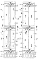
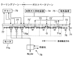
次に、ポストベークゾーン(POB)56とクーリングゾーン(COL)57を有する処理ブロック11cの構造について、より詳細に説明する。図4に処理ブロック11cの内部構造(つまり、ポストベークゾーン(POB)56とクーリングゾーン(COL)57の構成)を示す概略側面図を示す。
Next, the structure of the
ポストベークゾーン(POB)56は、基板Gを略水平姿勢で水平方向に搬送するための基板搬送機構71と、基板Gを加熱するために、基板搬送機構71による基板Gの搬送ルート上の所定の高さ位置に搬送ルートに沿って所定間隔で隙間73を設けながら配置された複数のパネル形状のヒータ72・72′と、これら複数のヒータ72・72′間に設けられた所定の隙間73へ所定温度に加熱されたガスを供給する加熱ガス供給装置74と、複数のヒータ72・72′間に設けられた所定の隙間73から吸気を行うための吸気装置75と、基板搬送機構71によって搬送される基板Gの裏面から基板Gを加熱するためのIR(赤外線)ヒータ76と、を備えている。
The post-bake zone (POB) 56 includes a
基板搬送機構71は、Y方向(基板搬送方向であるX方向に垂直な方向)を長軸方向としてX方向に所定間隔で並べられた複数の円柱状のローラー部材71aと、これらのローラー部材を回転させるためのローラー駆動手段、例えばモータ71bと、を有している。図4では4個のローラー部材71aを1組として、これらをモータ71b(全てを図示せず)で回転させる構造を示しているが、このような構成に限定されるものではなく、全てのローラー部材71aにモータ71bを直結させて回転駆動させてもよく、また、1つおきや2つおきにモータ71bによって回転駆動されるものと、基板Gとの摩擦により回転するフリーなものとを組み合わせた構成としてもよい。
The
ローラー部材71aとしては、図5の斜視図に示すように、その長軸方向の長さが、基板Gの幅(Y方向長さ)よりも長いものを用いる。これは、基板GにおいてX方向にローラー部材71aと接触する部分と接触しない帯状の部分ができると、基板Gの熱履歴に分布が生じてしまって縞模様等の転写痕が発生してしまうので、それを防止するためである。
As the
図6にヒータ72・72′の概略構造を示す斜視図を示す。この図6に示されるように、ヒータ72・72′は共に複数の小ヒータ72a・72bから構成されている。一辺の長さが1mを超えるような大型の基板Gを熱的に処理する場合には、これと同等以上の大きさのヒータが必要となるが、そのようなヒータでは、製造コストが高くなり、熱輻射の均一性も低下する。そこで、複数の既存の小ヒータ72a・72bを連結することにより、安価にしかも各小ヒータ72a・72bごとに温度調節を行うことでヒータ72・72′からの熱輻射を均一なものとすることができる。
FIG. 6 is a perspective view showing a schematic structure of the
このようにヒータ72を複数の小ヒータ72a・72bから構成する場合、一定の距離範囲内において小ヒータ72a・72bどうしの継ぎ目がX方向と平行にならないように、複数の小ヒータ72a・72bを連結する。小ヒータ72a・72bどうしの継ぎ目の直下では基板Gへの熱輻射が小さくなるので、この継ぎ目がX方向に長く存在すると、基板Gの熱処理均一性が悪くなり、基板Gに転写痕が発生してしまうが、継ぎ目のX方向長さを一定の範囲内とすることで、このような転写痕の発生を防止することができる。なお、「一定の範囲」は、ヒータ72・72′の設定温度やヒータ72・72′と基板Gとの間の距離(間隔)等によって、変化するので、これらの因子を考慮して、実際に基板Gに転写痕が発生することのないように設定される。ヒータ72・72′の下面と基板Gの上面との間隔は、基板Gに均一に熱輻射を行うことができるように、適宜設定すればよく、例えば、ヒータ72・72′の平均温度を120℃とした場合に、2mm以上50mm以下とすることができる。
When the
図6では2種類のヒータ72・72′を示したが、これはY方向に小ヒータ72a・72bを並べて構成されるブロックと、Y方向に小ヒータ72aのみを並べて構成されるブロックとを、X方向で3ブロック連結した構成としたからであり、これら各ブロックを2ブロック、4ブロックの交互連結とすれば、1種類のヒータで足りる。またヒータ72・72′は、図6に示したように、異なる大きさの小ヒータを組み合わせて構成してもよいし、同じ形状の小ヒータを組み合わせて構成することもできる。ヒータ72・72′の平面形状は必ずしも、矩形(正方形や長方形等)に限定されるものではなく、例えば、Y方向端においては、凹凸があっても構わない。このような小ヒータの平面形状は矩形のものに限定されず、三角形や六角形等の多角形のものも用いてもよい。
In FIG. 6, two types of
なお、基板Gの表裏で温度差が発生すると基板Gに反りが生じるので、基板Gの表裏の温度が同程度となるように、ヒータ72・72′とIRヒータ76の出力を制御する。ヒータ72・72′から基板Gの表面までの距離と、IRヒータ76から基板Gの裏面までの距離は異なるので、基板の設定温度に対するヒータ72・72′とIRヒータ76の出力の相関関係データをレジスト塗布・現像処理システム100の制御装置に記憶させておき、基板Gの設定処理温度に応じてその相関データを基にヒータ72・72′とIRヒータ76とを制御する。
If a temperature difference occurs between the front and back surfaces of the substrate G, the substrate G is warped. Therefore, the outputs of the
ヒータ72どうしの間に形成された隙間73は交互に、加熱ガス供給装置74から所定温度に加熱されたガスを供給するために、また、基板Gとヒータ72との間の空間からの吸気を行うために、利用される。加熱ガスを基板Gとヒータ72との間に供給することによって基板Gの加熱を促進することができ、このようにして加熱ガスを基板Gとヒータ72との間の空間に給排気を行うことによって、基板Gから発生する昇華物等を気流に乗せて、基板Gとヒータ72との間の空間から排除することができる。このような吸気系配管(つまり、吸気口(隙間73)〜吸気装置75の手前まで)に昇華物が固化しないように、吸気系配管を所定温度に加熱保持することも好ましい。
The
ヒータ72・72′としてX方向長さの短いものを用いて隙間73を多く形成すると、このような昇華物の排除がより容易となる。但し、その際に基板Gの加熱特性が低下しないように、ヒータ72・72′の形状および配置を考慮する必要がある。
If
加熱ガスの温度は基板Gの設定処理温度より低く、かつ、基板Gの設定処理温度とそれよりも10℃低い温度との間とすることが好ましい。加熱ガスの温度が設定処理温度よりも高いと基板Gを加熱しすぎるおそれがあり、また、基板Gの設定処理温度よりも10℃低い温度よりさらに低くなると、加熱ガスが噴射される位置(つまり、空隙73)の直下において基板Gが冷却されてしまい、基板Gに反りが生ずるおそれがある。 The temperature of the heating gas is preferably lower than the set processing temperature of the substrate G and between the set processing temperature of the substrate G and a temperature lower by 10 ° C. If the temperature of the heating gas is higher than the set processing temperature, the substrate G may be heated too much. If the temperature is further lower than the temperature lower by 10 ° C. than the setting processing temperature of the substrate G, the position where the heating gas is injected (that is, , The substrate G is cooled immediately below the gap 73), and the substrate G may be warped.
基板搬送機構71によって搬送される基板Gの裏面から基板Gを加熱するためのIR(赤外線)ヒータ76は、基板Gのみならず、ローラー部材71aを加熱するように配置することが好ましい。これによりローラー部材71aからの熱伝達および熱輻射によっても基板Gが加熱され、基板Gの乾燥時間を短縮することができる。このため、ローラー部材71aは、蓄熱性材料(例えば、セラミックス等)で構成されているものを用いることが好ましい。IRヒータ76に代えて、熱放射能を有するランプを用いてもよい。
The IR (infrared)
ポストベークゾーン(POB)56から基板Gを受け取り、冷却するクーリングゾーン(COL)57には、ポストベークゾーン(POB)56に設けられた基板搬送機構71が延設されており、ポストベークゾーン(POB)56から連続的に基板Gが略水平姿勢で搬送される。そして、クーリングゾーン(COL)57には、基板Gをその表面側から冷却するために基板Gの搬送ルート上の所定の高さ位置に設けられた冷却板77と、基板Gを裏面から冷却するために基板Gの裏面に冷却ガスを吹き付ける冷却ガス噴射装置78が配設されている。
A
冷却板77は、その内部に冷却媒体を通すための配管が埋設されており、チラー79との間で冷媒が循環するように構成されている。冷却板77どうしの隙間から、冷却板77と基板Gとの間の空間の温まったガスを吸気する構成とすることも好ましい。
The cooling
また、冷却ガス噴射装置78としては、例えば、冷媒中に設けられた配管内に窒素ガスまたは空気を通すことでガスを冷却し、ノズル78aから基板Gに向けて吹き付ける構成のものを用いることができる。このような冷却ガスの雰囲気にさらされることによってローラー部材71を冷却し、基板Gからローラー部材71aへの熱伝達により基板Gの冷却速度を速めることも好ましい。その場合、冷却されるローラー部材71aは、熱伝導性の高い材料、例えば、金属材料で構成することが好ましい。クーリングゾーン(COL)57に配設されるローラー部材71aは、内部に冷却水を循環させて冷却する構造としてもよい。
Further, as the cooling
なお、ポストベークゾーン(POB)56とクーリングゾーン(COL)57とでは設定温度に大きな差があるために、図示しないシャッタにより、ポストベークゾーン(POB)56とクーリングゾーン(COL)57を簡易的に遮断する、つまり基板Gを搬送するための隙間を確保しながら両者を仕切ることも好ましい。処理ブロック11cの構成は、基板Gに熱的処理を施す他の処理ブロック11d・12cにも同様に適用することができ、処理ブロック11cのアドヒージョン処理ゾーン(AD)52では、加熱したHMDSガス等の処理ガスが基板Gに供給される。
In addition, since there is a large difference in the set temperature between the post-bake zone (POB) 56 and the cooling zone (COL) 57, the post-bake zone (POB) 56 and the cooling zone (COL) 57 are simplified by a shutter (not shown). It is also preferable to partition the two while ensuring a gap for transporting the substrate G. The configuration of the
本発明は、LCDガラス基板等の大型基板のフォトリソグラフィー工程における加熱処理と冷却処理に好適である。 The present invention is suitable for heat treatment and cooling treatment in a photolithography process of a large substrate such as an LCD glass substrate.
1;第1処理部
2;第2処理部
3;第1搬送部
4;第2搬送部
5;インターフェース部
6;容器搬入出部
11a〜11d・12a〜12d;処理ブロック
56;ポストベークゾーン(POB)
57;クーリングゾーン(COL)
7l;基板搬送機構
71a;ローラー部材
72;ヒータ
74;加熱ガス供給装置
75;吸気装置
76;IR(赤外線)ヒータ
77;冷却板
78;冷却ガス噴射装置
100;レジスト塗布・現像処理システム
G;基板(LCD基板)
DESCRIPTION OF
57; Cooling zone (COL)
7l;
Claims (8)
基板を水平方向に搬送するための基板搬送機構と、
基板を加熱するために、前記基板搬送機構による基板の搬送ルート上の所定の高さ位置に当該搬送ルートに沿って所定間隔で隙間を設けながら配置された複数のパネル形状のヒータと、
を具備し、
前記ヒータはそれぞれ複数の小ヒータから構成され、前記複数の小ヒータの継ぎ目に起因して基板に転写痕が発生することを防止するために、前記複数の小ヒータはその継ぎ目が一定の距離範囲内において基板搬送方向と平行にならないように連結されていることを特徴とする熱的処理装置。 A thermal processing apparatus for performing thermal processing while conveying a substrate in a horizontal direction in a substantially horizontal posture,
A substrate transport mechanism for transporting the substrate in a horizontal direction;
In order to heat the substrate, a plurality of panel-shaped heaters arranged at predetermined intervals along the transfer route at predetermined height positions on the transfer route of the substrate by the substrate transfer mechanism,
Comprising
Each of the heaters is composed of a plurality of small heaters, and in order to prevent transfer marks from being generated on the substrate due to the joints of the plurality of small heaters, the joints of the plurality of small heaters have a certain distance range. The thermal processing apparatus is connected so as not to be parallel to the substrate transport direction.
前記加熱ガス供給装置からのガス供給ポイントと、前記吸気装置からの吸気ポイントは、基板搬送方向に沿って存在する前記複数のヒータ間の隙間に交互に設けられていることを特徴とする請求項1または請求項2に記載の熱的処理装置。 A heating gas supply device that supplies a gas heated to a predetermined temperature to a gap provided between the plurality of heaters; and an intake device for performing intake air from the gap provided between the plurality of heaters. And
The gas supply point from the heating gas supply device and the intake point from the intake device are alternately provided in a gap between the plurality of heaters existing along the substrate transfer direction. The thermal processing apparatus of Claim 1 or Claim 2.
さらに、前記基板搬送機構によって搬送される基板の裏面から当該基板を加熱するためのIRヒータまたは熱放射能を有するランプを具備し、
前記IRヒータまたは前記ランプによって前記ローラー部材が加熱され、前記ローラー部材から基板への熱伝達によっても当該基板が加熱されることを特徴とする請求項1から請求項3のいずれか1項に記載の熱的処理装置。 The substrate transport mechanism includes a plurality of cylindrical roller members arranged at predetermined intervals in the substrate transport direction with a direction perpendicular to the substrate transport direction as a major axis direction, and roller driving means for rotating the plurality of roller members And having
Furthermore, it comprises an IR heater for heating the substrate from the back surface of the substrate transported by the substrate transport mechanism or a lamp having thermal radiation,
The said roller member is heated by the said IR heater or the said lamp | ramp, The said board | substrate is heated also by the heat transfer from the said roller member to a board | substrate, The Claim 1 characterized by the above-mentioned. Thermal processing equipment.
Priority Applications (3)
| Application Number | Priority Date | Filing Date | Title |
|---|---|---|---|
| JP2005055944A JP2006245110A (en) | 2005-03-01 | 2005-03-01 | Heat-treating apparatus |
| TW095106655A TWI295415B (en) | 2005-03-01 | 2006-02-27 | Thermal processing unit |
| KR1020060019378A KR101237092B1 (en) | 2005-03-01 | 2006-02-28 | Thermal processing unit |
Applications Claiming Priority (1)
| Application Number | Priority Date | Filing Date | Title |
|---|---|---|---|
| JP2005055944A JP2006245110A (en) | 2005-03-01 | 2005-03-01 | Heat-treating apparatus |
Publications (2)
| Publication Number | Publication Date |
|---|---|
| JP2006245110A true JP2006245110A (en) | 2006-09-14 |
| JP2006245110A5 JP2006245110A5 (en) | 2007-04-19 |
Family
ID=37051248
Family Applications (1)
| Application Number | Title | Priority Date | Filing Date |
|---|---|---|---|
| JP2005055944A Pending JP2006245110A (en) | 2005-03-01 | 2005-03-01 | Heat-treating apparatus |
Country Status (3)
| Country | Link |
|---|---|
| JP (1) | JP2006245110A (en) |
| KR (1) | KR101237092B1 (en) |
| TW (1) | TWI295415B (en) |
Cited By (8)
| Publication number | Priority date | Publication date | Assignee | Title |
|---|---|---|---|---|
| JP2008160011A (en) * | 2006-12-26 | 2008-07-10 | Tokyo Electron Ltd | Substrate treating equipment |
| JP2008172104A (en) * | 2007-01-12 | 2008-07-24 | Tokyo Electron Ltd | Reflow processing system and reflow processing method |
| JP2008218593A (en) * | 2007-03-02 | 2008-09-18 | Tokyo Electron Ltd | Substrate-treating apparatus |
| JP2008224192A (en) * | 2007-03-15 | 2008-09-25 | Koyo Thermo System Kk | Continuous type kiln |
| JP2008311250A (en) * | 2007-06-12 | 2008-12-25 | Tokyo Electron Ltd | Reflow system and reflow method |
| JP2011066318A (en) * | 2009-09-18 | 2011-03-31 | Tokyo Electron Ltd | Heat processing apparatus |
| WO2011148716A1 (en) * | 2010-05-25 | 2011-12-01 | シャープ株式会社 | Bake device |
| JP2018029137A (en) * | 2016-08-18 | 2018-02-22 | 株式会社アルバック | Conveying device |
Families Citing this family (3)
| Publication number | Priority date | Publication date | Assignee | Title |
|---|---|---|---|---|
| KR100811695B1 (en) * | 2006-11-28 | 2008-03-11 | 엔티엠 주식회사 | Apparatus for drying substrate |
| KR101052758B1 (en) * | 2008-11-18 | 2011-08-01 | 세메스 주식회사 | Flat panel display device manufacturing device |
| KR102410492B1 (en) * | 2015-07-23 | 2022-06-20 | 삼성디스플레이 주식회사 | Glass molding apparatus |
Family Cites Families (3)
| Publication number | Priority date | Publication date | Assignee | Title |
|---|---|---|---|---|
| JPH09237965A (en) * | 1996-02-29 | 1997-09-09 | Furukawa Electric Co Ltd:The | Reflow furnace |
| JP3756402B2 (en) * | 2000-12-08 | 2006-03-15 | 富士写真フイルム株式会社 | Substrate transfer apparatus and method |
| JP2003332727A (en) * | 2002-05-15 | 2003-11-21 | Sony Corp | Heat shielding member and reflow apparatus |
-
2005
- 2005-03-01 JP JP2005055944A patent/JP2006245110A/en active Pending
-
2006
- 2006-02-27 TW TW095106655A patent/TWI295415B/en not_active IP Right Cessation
- 2006-02-28 KR KR1020060019378A patent/KR101237092B1/en not_active IP Right Cessation
Cited By (8)
| Publication number | Priority date | Publication date | Assignee | Title |
|---|---|---|---|---|
| JP2008160011A (en) * | 2006-12-26 | 2008-07-10 | Tokyo Electron Ltd | Substrate treating equipment |
| JP2008172104A (en) * | 2007-01-12 | 2008-07-24 | Tokyo Electron Ltd | Reflow processing system and reflow processing method |
| JP2008218593A (en) * | 2007-03-02 | 2008-09-18 | Tokyo Electron Ltd | Substrate-treating apparatus |
| JP2008224192A (en) * | 2007-03-15 | 2008-09-25 | Koyo Thermo System Kk | Continuous type kiln |
| JP2008311250A (en) * | 2007-06-12 | 2008-12-25 | Tokyo Electron Ltd | Reflow system and reflow method |
| JP2011066318A (en) * | 2009-09-18 | 2011-03-31 | Tokyo Electron Ltd | Heat processing apparatus |
| WO2011148716A1 (en) * | 2010-05-25 | 2011-12-01 | シャープ株式会社 | Bake device |
| JP2018029137A (en) * | 2016-08-18 | 2018-02-22 | 株式会社アルバック | Conveying device |
Also Published As
| Publication number | Publication date |
|---|---|
| KR101237092B1 (en) | 2013-02-25 |
| KR20060096903A (en) | 2006-09-13 |
| TW200641553A (en) | 2006-12-01 |
| TWI295415B (en) | 2008-04-01 |
Similar Documents
| Publication | Publication Date | Title |
|---|---|---|
| JP2006245110A (en) | Heat-treating apparatus | |
| JP4542577B2 (en) | Normal pressure drying apparatus, substrate processing apparatus, and substrate processing method | |
| JP4592787B2 (en) | Substrate processing equipment | |
| JP4384685B2 (en) | Normal pressure drying apparatus, substrate processing apparatus, and substrate processing method | |
| JP4384686B2 (en) | Normal pressure drying apparatus, substrate processing apparatus, and substrate processing method | |
| JP4341978B2 (en) | Substrate processing equipment | |
| CN100454482C (en) | Heat treatment unit, heat treatiment method, control program and computer-readable recording medium | |
| JP2009290207A (en) | Substrate processing apparatus and method used for manufacture of flat panel display | |
| JP4407971B2 (en) | Substrate processing equipment | |
| JP4638931B2 (en) | Substrate processing equipment | |
| JP2008160011A (en) | Substrate treating equipment | |
| JP4813583B2 (en) | Substrate processing equipment | |
| JP4804332B2 (en) | Baking apparatus and substrate processing apparatus | |
| JP4967013B2 (en) | SUBSTRATE PROCESSING APPARATUS, SUBSTRATE PROCESSING METHOD, AND RECORDING MEDIUM RECORDING PROGRAM FOR EXECUTING THE SUBSTRATE PROCESSING METHOD | |
| JP2011103422A (en) | Substrate processing apparatus | |
| JP4954642B2 (en) | Development processing apparatus and development processing method | |
| JP4028351B2 (en) | Baking method and baking apparatus | |
| JP7405889B2 (en) | Substrate processing equipment and substrate processing method | |
| JP4897035B2 (en) | SUBSTRATE PROCESSING APPARATUS, SUBSTRATE PROCESSING METHOD, AND RECORDING MEDIUM RECORDING PROGRAM FOR EXECUTING THE SUBSTRATE PROCESSING METHOD | |
| TWI833460B (en) | Substrate processing apparatus and substrate processing method | |
| JP2004022992A (en) | Method and apparatus for heat treatment | |
| JP2004200574A (en) | Heat treatment device | |
| TW202336822A (en) | Substrate processing apparatus and substrate processing method | |
| JP4796040B2 (en) | Substrate processing apparatus, substrate processing method, and substrate manufacturing method | |
| JP2000068187A (en) | Apparatus and method of heat-treating substrate |
Legal Events
| Date | Code | Title | Description |
|---|---|---|---|
| A621 | Written request for application examination |
Free format text: JAPANESE INTERMEDIATE CODE: A621 Effective date: 20061113 |
|
| A521 | Written amendment |
Free format text: JAPANESE INTERMEDIATE CODE: A523 Effective date: 20070228 |
|
| A131 | Notification of reasons for refusal |
Free format text: JAPANESE INTERMEDIATE CODE: A131 Effective date: 20090811 |
|
| A521 | Written amendment |
Free format text: JAPANESE INTERMEDIATE CODE: A523 Effective date: 20091009 |
|
| A02 | Decision of refusal |
Free format text: JAPANESE INTERMEDIATE CODE: A02 Effective date: 20091124 |
|
| A521 | Written amendment |
Free format text: JAPANESE INTERMEDIATE CODE: A523 Effective date: 20110602 |
|
| A521 | Written amendment |
Free format text: JAPANESE INTERMEDIATE CODE: A523 Effective date: 20110602 |