JP2006228471A - Battery locking mechanism of electronic apparatus - Google Patents

Battery locking mechanism of electronic apparatus Download PDF

Info

Publication number
JP2006228471A
JP2006228471A JP2005038251A JP2005038251A JP2006228471A JP 2006228471 A JP2006228471 A JP 2006228471A JP 2005038251 A JP2005038251 A JP 2005038251A JP 2005038251 A JP2005038251 A JP 2005038251A JP 2006228471 A JP2006228471 A JP 2006228471A
Authority
JP
Japan
Prior art keywords
battery
lock mechanism
lock
electronic device
slider plate
Prior art date
Legal status (The legal status is an assumption and is not a legal conclusion. Google has not performed a legal analysis and makes no representation as to the accuracy of the status listed.)
Pending
Application number
JP2005038251A
Other languages
Japanese (ja)
Inventor
Hiroshi Tsutsumitake
浩 堤竹
Current Assignee (The listed assignees may be inaccurate. Google has not performed a legal analysis and makes no representation or warranty as to the accuracy of the list.)
Sony Corp
Original Assignee
Sony Corp
Priority date (The priority date is an assumption and is not a legal conclusion. Google has not performed a legal analysis and makes no representation as to the accuracy of the date listed.)
Filing date
Publication date
Application filed by Sony Corp filed Critical Sony Corp
Priority to JP2005038251A priority Critical patent/JP2006228471A/en
Publication of JP2006228471A publication Critical patent/JP2006228471A/en
Pending legal-status Critical Current

Links

Images

Classifications

    • YGENERAL TAGGING OF NEW TECHNOLOGICAL DEVELOPMENTS; GENERAL TAGGING OF CROSS-SECTIONAL TECHNOLOGIES SPANNING OVER SEVERAL SECTIONS OF THE IPC; TECHNICAL SUBJECTS COVERED BY FORMER USPC CROSS-REFERENCE ART COLLECTIONS [XRACs] AND DIGESTS
    • Y02TECHNOLOGIES OR APPLICATIONS FOR MITIGATION OR ADAPTATION AGAINST CLIMATE CHANGE
    • Y02EREDUCTION OF GREENHOUSE GAS [GHG] EMISSIONS, RELATED TO ENERGY GENERATION, TRANSMISSION OR DISTRIBUTION
    • Y02E60/00Enabling technologies; Technologies with a potential or indirect contribution to GHG emissions mitigation
    • Y02E60/10Energy storage using batteries

Abstract

<P>PROBLEM TO BE SOLVED: To enable further downsizing of an electronic apparatus with due consideration of arrangement and a structure of its battery lock mechanism. <P>SOLUTION: A battery mounting part for mounting a battery in free detachment is provided on one face of a case of the electronic apparatus, and at the same time, a lock mechanism for locking the battery is provided on an adjoining face of the battery mounting part of the case. The lock mechanism consists of a lock slider plate biased in one direction to get engaged with and locked to the battery, and a slide button fitted through the slider plate and a turning lever and moving the lock slider plate in another direction to take off the battery, the slide button and the lock slider plate sliding on the surface or rear face of the adjoining face. <P>COPYRIGHT: (C)2006,JPO&NCIPI

Description

本発明は、電子機器の駆動電源であるバッテリーを電子機器に装着した状態でロックすると共にそのロックを解除するバッテリーロック機構に関する。   The present invention relates to a battery lock mechanism that locks a battery as a driving power source for an electronic device while the battery is mounted on the electronic device and releases the lock.

従来、電子機器のバッテリーロック機構としては、例えば下記の特許文献1に記載されるようなものがある。
即ちこのバッテリーロック機構は、電子機器( ビデオカメラ) の背面側にバッテリーが装着され、その状態でバッテリーは、バッテリー装着面に突出するロック部材が係合してロックされるようになっている。そしてこのバッテリーロック機構では、ロック部材の横に押釦式のロック解除部材が設けられており、このロック解除部材を押すことでロック部材がバッテリーから外れ、これによってバッテリーのロックが解除されて電子機器からバッテリーを取り外すことができる構造となっている。
特開平7−312214号公報
Conventionally, as a battery lock mechanism of an electronic device, for example, there is one described in Patent Document 1 below.
That is, in this battery lock mechanism, a battery is mounted on the back side of an electronic device (video camera), and in this state, the battery is locked by engaging a locking member protruding from the battery mounting surface. In this battery locking mechanism, a push button type unlocking member is provided beside the locking member, and the locking member is released from the battery by pushing the unlocking member, and thereby the battery is unlocked to release the electronic device. The battery can be removed from the structure.
Japanese Patent Laid-Open No. 7-312214

この特許文献1に記載のバッテリーロック機構は、ロック部材の横に押釦式のロック解除部材を配置した構成であるため、機構の配置に大きなスペースを必要としていた。近年、電子機器は一層の小型化が進んでおり、内部構造の省スペース化が要求されているが、特許文献1に記載のバッテリーロック機構では、この要求に応えることはできない。
本発明は斯かる点に鑑みてなされたもので、電子機器におけるバッテリーロック機構の配置構成を考慮し、電子機器の一層の小型化を可能とすることを目的としている。
Since the battery lock mechanism described in Patent Document 1 has a configuration in which a push button type unlocking member is arranged beside the lock member, a large space is required for the arrangement of the mechanism. In recent years, electronic devices have been further miniaturized, and space saving of the internal structure is required. However, the battery lock mechanism described in Patent Document 1 cannot meet this requirement.
The present invention has been made in view of such a point, and an object of the present invention is to further reduce the size of the electronic device in consideration of the arrangement configuration of the battery lock mechanism in the electronic device.

本発明電子機器のバッテリーロック機構は、電子機器の筐体の一面にバッテリーを着脱自在に装着するバッテリー装着部を設けると共にこの筐体のバッテリー装着部の隣接面にこのバッテリーをロックするロック機構を設けるようにし、このロック機構は、このバッテリーと一方向に付勢されて係合しロックするロックスライダ板と、このロックスライダ板と回動レバーを介して設けられ、この一方向に移動することにより、このロックスライダ板を他方向に移動し、このバッテリーを取り外すスライドボタンとより成り、このスライドボタン及びこのロックスライダ板はこの隣接面の表面又は裏面を摺動するものである。   The battery lock mechanism of the electronic device according to the present invention is provided with a battery mounting portion for detachably mounting the battery on one surface of the housing of the electronic device and a lock mechanism for locking the battery on the adjacent surface of the battery mounting portion of the housing. The lock mechanism is provided via a lock slider plate that is biased and engaged and locked in one direction with the battery, and the lock slider plate and a rotation lever. The lock mechanism moves in this one direction. Thus, the lock slider plate is moved in the other direction, and a slide button for removing the battery is formed. The slide button and the lock slider plate slide on the front surface or the back surface of the adjacent surface.

本発明によれば、ロック機構をバッテリーを着脱自在に装着するバッテリー装着部の隣接面にスライドボタンとロックスライダ板とが回転レバーで逆方向に移動すると共にこのスライドボタン及びこのロックスライダ板をこの隣接面の表面又は裏面を摺動するようにしたので、薄型で操作性の良いロック機構を得ることができる。   According to the present invention, the slide button and the lock slider plate are moved in the reverse direction by the rotary lever on the adjacent surface of the battery mounting portion where the battery is detachably mounted, and the slide button and the lock slider plate are Since the front surface or the back surface of the adjacent surface is slid, a thin and easy-to-operate lock mechanism can be obtained.

以下、図面を参照しながら本発明の電子機器のバッテリーロック機構を実施するための最良の形態の例について詳細に説明する。
先ず、本発明が適用される電子機器として、撮像装置の構成の例につき図1〜図7を参照して説明する。
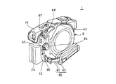
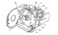
図1は斜視図、図2は表示装置を開いた後方からの斜視図、図3は表示装置を開いた前方からの斜視図、図4はディスク側の後方から見た斜視図、図5は底面側から見た斜視図、図6はディスク蓋を開いた前方から見た斜視図、図7は同じくディスク状記録媒体を装着した状態の斜視図である。
Hereinafter, an example of the best mode for carrying out a battery lock mechanism of an electronic apparatus according to the present invention will be described in detail with reference to the drawings.
First, as an electronic apparatus to which the present invention is applied, an example of the configuration of an imaging apparatus will be described with reference to FIGS.
1 is a perspective view, FIG. 2 is a perspective view from the rear with the display device opened, FIG. 3 is a perspective view from the front with the display device opened, FIG. 4 is a perspective view seen from the rear on the disk side, and FIG. FIG. 6 is a perspective view seen from the front side when the disc lid is opened, and FIG. 7 is a perspective view showing a state in which the disc-shaped recording medium is mounted.

この撮像装置1は、情報記憶メディアであるディスク状記録媒体の一具体例として直径8cmのDVD(Digital Versatile Disc)を使用し、光学的な画像をCCD(固体撮像素子)で電気的な信号に変換してDVDに記録したり、液晶モニタ等の表示装置に表示できるようにしたもの(以下「ディスク式撮像装置」という。)である。しかしながら、ディスク状記録媒体としては、DVDに限定されるものではなく、CD−ROMその他の記録可能な光学ディスクを用いることができることは勿論のこと、例えば光磁気ディスク、磁気ディスク等のように他の記録方式のディスク状記録媒体を適用できるものである。   This imaging apparatus 1 uses a DVD (Digital Versatile Disc) having a diameter of 8 cm as a specific example of a disc-shaped recording medium that is an information storage medium, and converts an optical image into an electrical signal by a CCD (solid-state imaging device). This is one that can be converted and recorded on a DVD or displayed on a display device such as a liquid crystal monitor (hereinafter referred to as “disk-type imaging device”). However, the disc-shaped recording medium is not limited to the DVD, and it is possible to use a CD-ROM or other recordable optical disc, for example, a magneto-optical disc, a magnetic disc, or the like. A disc-shaped recording medium of the above recording method can be applied.

このディスク式撮像装置1は、着脱自在に装着されるDVD2を回転駆動して情報信号の記録(書き込み)及び再生(読み出し)を行うディスクドライブ装置3(図6、図7を参照)と、このディスクドライブ装置3の駆動制御等を行う図示しない制御回路と、被写体の像を光として取り込んでCCDに導くレンズ装置4と、これらディスクドライブ装置3等が収納される外装ケース5と、この外装ケース5に回動自在に取り付けられてディスク収納部6を開閉可能に覆うことができるディスク蓋7等を備えて構成されている。   The disc type image pickup device 1 includes a disc drive device 3 (see FIGS. 6 and 7) for recording (writing) and reproducing (reading) information signals by rotationally driving a DVD 2 that is detachably mounted. A control circuit (not shown) that controls the drive of the disk drive device 3, a lens device 4 that takes an image of a subject as light and guides it to the CCD, an exterior case 5 in which these disk drive device 3 and the like are stored, and this exterior case 5 is provided with a disc lid 7 or the like that is rotatably attached to 5 and can open and close the disc storage portion 6.

外装ケース5は、三重に重ね合わせるように組み合わされるディスク側パネル、中央部パネル及び表示装置側パネルと、レンズ装置4の光軸方向の前後に配置されてこれらのパネルと組み合わされるフロントパネル及び背面側のバッテリー装着パネル12と、中央部パネルの内側に配置される図に表れない仕切りパネルとからなり、これらのパネルによって中空の筐体が構成されている。そして、仕切りパネルのディスク側パネル側の面に、ディスクドライブ装置3が4箇所に設けられたマウントインシュレータを介して弾性的に支持されている。これらのパネルは、互いに重ね合わされた適当な部分において、或いは他の部材を介して固定ネジからなる固着手段によって組立・分解可能に構成されている。   The outer case 5 includes a disk side panel, a center panel, and a display device side panel that are combined so as to be overlapped in triplicate, and a front panel and a rear surface that are arranged in front and rear in the optical axis direction of the lens device 4 and combined with these panels. The battery mounting panel 12 on the side and a partition panel not shown in the figure arranged inside the central panel are formed into a hollow casing. The disk drive device 3 is elastically supported on the surface on the disk side panel side of the partition panel via mount insulators provided at four locations. These panels are configured to be assembled and disassembled by a fixing means including a fixing screw at an appropriate portion overlapped with each other or through another member.

レンズ装置4は、外装ケース5の上部に内蔵された状態で固定されていて、その対物レンズ15がフロントパネルの上部を前方に貫通して前面に露出されている。図示しないが、外装ケース5の内部において、レンズ装置4の後方にCCDが配置されており、そのCCDの後方にビューファインダ16が配置されている。   The lens device 4 is fixed in a state of being built in the upper part of the outer case 5, and the objective lens 15 penetrates the upper part of the front panel forward and is exposed to the front surface. Although not shown, a CCD is disposed behind the lens device 4 inside the exterior case 5, and a viewfinder 16 is disposed behind the CCD.

ビューファインダ16は外装ケース5の上部に露出されていて、ファインダ移動機構によってレンズ装置4の光軸方向へ所定距離だけ進退移動可能に構成されている。このビューファインダ16は、前側を回動中心として後側が上下方向へ回動可能に構成されている。これによりビューファインダ16は、レンズ装置4の光軸と平行をなす水平状態から、後部を上方へ持ち上げた上向き状態まで所定角度範囲(本例では約90度)内で任意角度に角度調節可能とされている。このビューファインダ16の角度調整は、ファインダ移動機構の前端部から後端部までの如何なる位置においても行うことができる。   The viewfinder 16 is exposed at the upper part of the exterior case 5 and is configured to be moved forward and backward by a predetermined distance in the optical axis direction of the lens device 4 by a finder moving mechanism. The viewfinder 16 is configured such that the rear side can be rotated in the vertical direction with the front side as a rotation center. As a result, the viewfinder 16 can be adjusted to an arbitrary angle within a predetermined angle range (in this example, about 90 degrees) from a horizontal state parallel to the optical axis of the lens device 4 to an upward state in which the rear part is lifted upward. Has been. The angle of the viewfinder 16 can be adjusted at any position from the front end portion to the rear end portion of the viewfinder moving mechanism.

更に、外装ケース5の上部には、前側に内蔵マイクロホン22が配置され、その後方にビデオライトや外付けマイクロホン等のアクセサリーが着脱自在に装着されるアクセサリーシュー17が取り付けられている。アクセサリーシュー17はビューファインダ16の前方に配置されている。このアクセサリーシュー17には、通常、不使用時に空間部分を埋める蓋体をなすシューキャップ18が装着される。   Further, an upper part of the outer case 5 is provided with a built-in microphone 22 on the front side, and an accessory shoe 17 to which accessories such as a video light and an external microphone are detachably attached. The accessory shoe 17 is disposed in front of the viewfinder 16. The accessory shoe 17 is usually fitted with a shoe cap 18 that forms a lid that fills the space when not in use.

また、フロントパネルの前面には、上から順にリモコン受光部20とマイク端子とが配置されている。リモコン受光部20は、リモコン操作のための受信部である。このリモコン受光部20は、焦点を自動的に調整する等のために用いられる赤外線を発光する赤外線発光部も兼ねている。また、マイク端子は映像端子と音声端子とからなり、これらの端子は端子カバーによって開閉可能に覆われている。   Further, a remote control light receiving unit 20 and a microphone terminal are arranged in order from the top on the front surface of the front panel. The remote control light receiving unit 20 is a receiving unit for remote control operation. The remote control light receiving unit 20 also serves as an infrared light emitting unit that emits infrared light used for automatically adjusting the focus. The microphone terminal includes a video terminal and an audio terminal, and these terminals are covered with a terminal cover so as to be opened and closed.

図2、図4、図5に示すように、外装ケース5の一部を構成するバッテリー装着パネル12には、撮像装置の駆動用電源であるバッテリー24が着脱自在に装着されるバッテリー装着部25が設けられている。バッテリー装着部25は、バッテリー装着パネル12の背面及び下面に開口されていて、バッテリー24を下方から差し込んで装着し、同方向へ取り外し可能とされている。更に、バッテリー装着パネル12には、吊り下げ用ストラップのための2個の支持金具が取り付けられている。2個の支持金具のうち、一方の支持金具は右サイドの上部に配置され、他方の支持金具は左サイドの下部に配置されている。   As shown in FIGS. 2, 4, and 5, a battery mounting portion 25 in which a battery 24 that is a driving power source of the imaging device is detachably mounted on a battery mounting panel 12 that constitutes a part of the exterior case 5. Is provided. The battery mounting portion 25 is opened at the back and bottom surfaces of the battery mounting panel 12 so that the battery 24 can be inserted and mounted from below and can be removed in the same direction. Further, the battery mounting panel 12 is provided with two support fittings for hanging straps. Of the two support brackets, one support bracket is disposed at the upper part of the right side, and the other support bracket is disposed at the lower part of the left side.

図2及び図3に示すように、外装ケース5の表示装置側パネル10には、表示装置28が姿勢変更可能に取り付けられている。表示装置28は、平板状の液晶モニタ29と、この液晶モニタ29が収納されたパネルケース30と、このパネルケース30を外装ケース5に対して姿勢変更可能に支持するパネル支持部31とから構成されている。   As shown in FIGS. 2 and 3, a display device 28 is attached to the display device side panel 10 of the outer case 5 so that the posture can be changed. The display device 28 includes a flat liquid crystal monitor 29, a panel case 30 in which the liquid crystal monitor 29 is accommodated, and a panel support portion 31 that supports the panel case 30 with respect to the exterior case 5 so that the posture can be changed. Has been.

パネル支持部31は、垂直軸を回動中心としてパネルケース30を水平方向に略90度回動可能とした水平回動機能と、水平軸を回動中心としてパネルケース30を前後方向に略180度回動可能とした前後回動機能とを有している。これにより表示装置28は、図1に示す収納状態と、図2に示すパネルケース30を90度回動させて液晶モニタ29を後方へ対向させた状態と、図2の状態からパネルケース30を180度回動させて液晶モニタ29を前方へ対向させた状態と、それらの中間位置の状態とを任意に取ることができる。   The panel support unit 31 has a horizontal rotation function that allows the panel case 30 to be rotated about 90 degrees in the horizontal direction about the vertical axis, and the panel case 30 about 180 in the front-rear direction about the horizontal axis. It has a front / rear rotation function that can be rotated at a time. Accordingly, the display device 28 moves the panel case 30 from the storage state shown in FIG. 1, the state in which the panel case 30 shown in FIG. A state in which the liquid crystal monitor 29 is turned forward by rotating 180 degrees and a state at an intermediate position thereof can be arbitrarily taken.

更に、表示装置側パネル10には、パネルケース30によって開閉自在に覆われる操作ボタンからなる内側操作部と、パネルケース30の上方に配された操作ボタンからなる外側操作部が設けられている。   Further, the display device side panel 10 is provided with an inner operation portion composed of operation buttons which are covered with a panel case 30 so as to be freely opened and closed, and an outer operation portion composed of operation buttons arranged above the panel case 30.

ディスク収納部6は、ディスクドライブ装置3の一部を露出させるための開口部を有する一定領域からなり、この例では直径が8cmのディスク状記録媒体に対応する大きさの領域として形成されている。このディスク収納部6の略中央部にはディスクドライブ装置3のテーブル回転装置35が配置され、その中央部に位置するターンテーブル36に対して、ディスク状記録媒体の一具体例を示す直径8cmのDVD2が装着可能とされている。   The disk storage unit 6 is formed of a certain area having an opening for exposing a part of the disk drive device 3, and in this example, is formed as an area of a size corresponding to a disk-shaped recording medium having a diameter of 8 cm. . A table rotation device 35 of the disk drive device 3 is arranged at a substantially central portion of the disk storage portion 6, and a turntable 36 positioned at the center portion has a diameter of 8 cm showing a specific example of the disk-shaped recording medium. DVD2 can be mounted.

このテーブル回転装置35が配置されたディスク収納部6は、図6、図7に示すように、ディスク側パネル8に側面部を回動自在に支持されたディスク蓋7によって開閉可能に覆われている。ディスク蓋7は、ディスク収納部6の形状に見合う形状とされていて、ディスク収納部6の開口側を覆う平面部と、この平面部の外周縁の略全周に亘って連続する周面部を有している。ディスク蓋7の周面部は、ディスク側パネルのディスク収納部6の外周側切欠き部と嵌り合うように構成されている。   As shown in FIGS. 6 and 7, the disk storage unit 6 in which the table rotating device 35 is arranged is covered with a disk lid 7 whose side surface is rotatably supported by the disk side panel 8 so as to be opened and closed. Yes. The disc lid 7 has a shape commensurate with the shape of the disc storage portion 6, and includes a flat portion covering the opening side of the disc storage portion 6 and a peripheral surface portion continuous over substantially the entire circumference of the outer peripheral edge of the flat portion. Have. The peripheral surface portion of the disc lid 7 is configured to fit with the outer peripheral side cutout portion of the disc storage portion 6 of the disc side panel.

本例で示すディスク蓋7は、外周縁一周の略5/6(約300度)が円形(円形部分は全体の略3/4以上あれば良い。)とされたシェル形をなしていて、残りの部分が直線からなる方形部とされている。この方形部には、ディスク蓋7を開閉動作させるための回動中心となる蓋回動軸部39が取り付けられている。蓋回動軸部39は、図示しないが、方形部を貫通する支持軸と、この支持軸の両端を固定的に支持する一対の軸受片を有する軸受部材とからなり、軸受部材をディスク側パネルに固定することによってディスク蓋7が回動自在に支持されている。この蓋回動軸部39には、ディスク蓋7の最大開き角度(例えば、90度)を設定するストッパー部が設けられている。   The disk lid 7 shown in this example has a shell shape in which approximately 5/6 (about 300 degrees) of the circumference of the outer peripheral edge is circular (the circular portion may be approximately 3/4 or more of the whole). The remaining part is a square part made of a straight line. A lid rotation shaft portion 39 serving as a rotation center for opening and closing the disk lid 7 is attached to the rectangular portion. Although not shown, the lid rotation shaft portion 39 includes a support shaft that penetrates the rectangular portion and a bearing member that has a pair of bearing pieces that support both ends of the support shaft in a fixed manner. The disc lid 7 is rotatably supported by being fixed to. The lid rotation shaft portion 39 is provided with a stopper portion for setting a maximum opening angle (for example, 90 degrees) of the disc lid 7.

このような蓋回動軸部39が、その支持軸の軸方向を上下方向に設定してディスク側パネルに取り付けられている。これにより、ディスク蓋7が蓋回動軸部39を介してディスク側パネルの後部に回動可能に支持されている。その結果、ディスク蓋7は、ディスク式撮像装置1の正面を前側として前開きによって側方へ略90度開放動作させることができる。なお、蓋回動軸部39には、一定の開放角度の範囲内においてディスク蓋7を任意の開放位置で静止させることができると共に、その開放角度を超えたときにはディスク蓋7を開放側へ付勢するようにバネ部材が装着されている。   Such a lid rotation shaft portion 39 is attached to the disk side panel with the axial direction of the support shaft set in the vertical direction. Thereby, the disc lid 7 is rotatably supported on the rear portion of the disc side panel via the lid rotation shaft portion 39. As a result, the disc cover 7 can be opened approximately 90 degrees to the side by front opening with the front of the disc type imaging device 1 as the front side. The lid rotation shaft portion 39 can stop the disc lid 7 at an arbitrary opening position within a certain opening angle range, and attach the disc lid 7 to the opening side when the opening angle is exceeded. A spring member is mounted so as to be biased.

このディスク側パネルと重ね合わされる中央部パネルの上面部の略中央部から前面部の下部に亘る部分には、内側となる表示装置側パネル側に傾斜させることによって凹部となるくびれが設定されている。このくびれを有するディスク側パネル及び中央部パネルの円弧状をなす部分によってディスク式撮像装置1を握って保持するためのグリップ部43が構成されている。   A constriction that becomes a recess is set by tilting toward the inner side of the display device side panel in the portion extending from the approximate center of the upper surface of the center panel overlapped with the disk side panel to the lower part of the front surface. Yes. A grip portion 43 for gripping and holding the disc type imaging device 1 is constituted by the arc-shaped portions of the disc side panel and the central portion panel having the constriction.

このような中央部パネルとディスク側パネルの間には、ディスク蓋7の蓋開閉機構が設けられている。この蓋開閉機構は、ディスク収納部6を閉じた状態のディスク蓋7を、その閉じ状態においてロックする機能と、そのロックを解除する機能とを有するものである。   A lid opening / closing mechanism for the disk lid 7 is provided between the central panel and the disk side panel. This lid opening / closing mechanism has a function of locking the disk lid 7 in a state of closing the disk storage portion 6 in the closed state and a function of releasing the lock.

また、図3、図4及び図5等に示すように、ディスク側パネルには、ディスク蓋7を囲うようにハンドストラップ60が取り付けられている。ハンドストラップ60は、外装ケース5の把持部とされたグリップ部43を握るユーザーの手の部分を支えて、ディスク式撮像装置1の取り落とし等を防止するものである。   As shown in FIGS. 3, 4 and 5, a hand strap 60 is attached to the disk side panel so as to surround the disk lid 7. The hand strap 60 supports the part of the user's hand that grips the grip portion 43 that is the grip portion of the outer case 5, and prevents the disk-type imaging device 1 from being removed.

このハンドストラップ60は、両端がディスク側パネルに固定された支持ベルト61と、この支持ベルト61に装着されてユーザーの手の甲部分に当接される保護パッド62から構成されている。支持ベルト61の一端はディスク側パネルの前側下部に固定された取付金具63に連結され、他端はディスク側パネルの後側中途部に設けた貫通穴から内側に挿入されて、その内部に取り付けられた取付金具に固定されている。   The hand strap 60 includes a support belt 61 whose both ends are fixed to the disk side panel, and a protective pad 62 which is attached to the support belt 61 and comes into contact with the back of the user's hand. One end of the support belt 61 is connected to a mounting bracket 63 fixed to the front lower part of the disk side panel, and the other end is inserted inside through a through hole provided in the rear halfway part of the disk side panel and attached to the inside thereof. Fixed to the mounting bracket.

図3、図4等に示すように、ディスク側パネルの後部には、電源ボタン64とモード切換ダイヤル65と録画ボタン66が配置されている。モード切換ダイヤル65はリング状をなしていて、その穴内に電源ボタン64が収納されている。電源ボタン64はプッシュ・プッシュ方式のスイッチ手段からなり、その押圧動作によって電源バッテリー24からの電力供給がオン・オフされる。モード切換ダイヤル65は録画等の動作モードを選択するためのもので、その回動操作によって「静止画モード」と「動画モード」と「見る・編集モード」との3態様の中から任意のモードを選択することができる。また、録画ボタン66はプッシュ・プッシュ方式のスイッチ手段からなり、その押圧動作によって動画撮影のスタートとストップが繰り返される。   As shown in FIGS. 3 and 4, a power button 64, a mode switching dial 65, and a recording button 66 are arranged at the rear of the disk side panel. The mode switching dial 65 has a ring shape, and a power button 64 is accommodated in the hole. The power button 64 is composed of push-push type switch means, and the power supply from the power battery 24 is turned on and off by the pressing operation. The mode switching dial 65 is used to select an operation mode such as recording, and any mode can be selected from three modes of “still image mode”, “moving image mode”, and “view / edit mode” by rotating the mode dial 65. Can be selected. The recording button 66 includes push-push type switch means, and the start and stop of moving image shooting are repeated by the pressing operation.

更に、ディスク側パネルの後側上部には、シャッタボタン67とズームレバー68が配置されている。シャッタボタン67は静止画を撮影するためのもので、その押圧操作により、1回の押圧操作毎に1つの静止画が撮影される。また、ズームレバー68は撮影時や再生時等において画像を拡大するためのもので、その操作量に応じて一定の範囲内で倍率を無段階に調整することができる。   Further, a shutter button 67 and a zoom lever 68 are disposed on the upper rear side of the disk side panel. The shutter button 67 is for photographing a still image, and one still image is photographed for each pressing operation by the pressing operation. The zoom lever 68 is for enlarging an image at the time of shooting or reproduction, and the magnification can be adjusted steplessly within a certain range according to the operation amount.

前述したように外装ケース5の内部は仕切りパネルによって左右方向(レンズ装置4の光軸と交差する方向)に仕切られており、これにより、ディスク蓋7側の第1の室と表示装置側の第2の室が形成されている。仕切りパネルは板状の部材からなり、固定ネジによって外装ケース5の内部に締付固定されている。   As described above, the interior of the outer case 5 is partitioned in the left-right direction (the direction intersecting the optical axis of the lens device 4) by the partition panel, whereby the first chamber on the disc lid 7 side and the display device side are separated. A second chamber is formed. The partition panel is made of a plate-like member and is fastened and fixed inside the outer case 5 by a fixing screw.

図示しないが、外装ケース5の第1の室にはディスクドライブ装置3が収納され、第2の室にはレンズ装置4と制御回路部等が収納されている。そのため、仕切りパネルの一面側にはディスクドライブ装置3を支持するための複数個の支持突起が設けられ、他面側にはレンズ装置4やプリント基板等を支持するための複数個の支持片が設けられている。制御回路部は、例えば、マイクロコンピュータや記憶装置(RAM,ROM)、コンデンサや抵抗その他の電子部品と、これらの電子部品が搭載される回路基板等によって構成される。   Although not shown, the disk drive device 3 is accommodated in the first chamber of the outer case 5, and the lens device 4, the control circuit unit, and the like are accommodated in the second chamber. Therefore, a plurality of support protrusions for supporting the disk drive device 3 are provided on one side of the partition panel, and a plurality of support pieces for supporting the lens device 4 and the printed circuit board are provided on the other side. Is provided. The control circuit unit includes, for example, a microcomputer, a storage device (RAM, ROM), a capacitor, a resistor, and other electronic components, and a circuit board on which these electronic components are mounted.

図6に示すように、ディスクドライブ装置3は、仕切りパネルに取り付けられるメカシャーシ37と、このメカシャーシ37に固定されるテーブル回転装置35と、ピックアップ装置の一具体例を示す光学ピックアップ装置71等を備えて構成されている。メカシャーシ37は導電性の板材で形成されていて、絶縁性材料で形成された弾性体からなる複数個のマウントインシュレータを介して仕切りパネルに弾性的に支持されている。   As shown in FIG. 6, the disk drive device 3 includes a mechanical chassis 37 attached to the partition panel, a table rotating device 35 fixed to the mechanical chassis 37, an optical pickup device 71 showing a specific example of the pickup device, and the like. It is configured with. The mechanical chassis 37 is made of a conductive plate material, and is elastically supported by the partition panel via a plurality of mount insulators made of an elastic body made of an insulating material.

このように仕切りパネルに取り付けられたメカシャーシ37は、十分に大きな強度を有する枠状の部材によって構成されている。メカシャーシ37と仕切りパネルの導体部分は、図示しないアース部材によって互いに導通されていて、静電気等を外部に放出し易い構造とされている。このメカシャーシ37に搭載されたテーブル回転装置35は、メカシャーシ37に固定されたスピンドルモータと、このスピンドルモータの回転部に固定されたターンテーブル36とから構成されている。   The mechanical chassis 37 attached to the partition panel in this way is constituted by a frame-shaped member having a sufficiently large strength. The conductor portions of the mechanical chassis 37 and the partition panel are electrically connected to each other by a ground member (not shown), and are configured to easily discharge static electricity or the like to the outside. The table rotating device 35 mounted on the mechanical chassis 37 includes a spindle motor fixed to the mechanical chassis 37 and a turntable 36 fixed to a rotating portion of the spindle motor.

ターンテーブル36は、DVD2のセンタ穴が嵌合される嵌合部と、センタ穴の周縁部が載置される載置部とからなっている。更に、ターンテーブル36の嵌合部には、DVD2のセンタ穴の周縁部に係合してDVD2を保持する複数個の係合爪が周方向に複数個設けられている。各係合爪はスプリングによって半径方向外側へ付勢されており、このスプリングのバネ力によってDVD2が嵌合部に位置決め固定される。   The turntable 36 includes a fitting portion into which the center hole of the DVD 2 is fitted, and a placement portion on which the peripheral portion of the center hole is placed. Further, a plurality of engaging claws for engaging the peripheral edge of the center hole of the DVD 2 and holding the DVD 2 are provided in the fitting portion of the turntable 36 in the circumferential direction. Each engaging claw is urged radially outward by a spring, and the DVD 2 is positioned and fixed to the fitting portion by the spring force of the spring.

また、光学ピックアップ装置71は、DVD2の情報記録面に対向されるピックアップレンズを有する二軸アクチュエータと、この二軸アクチュエータが搭載されたスライド部材等を備えて構成されている。スライド部材は、図に表れない2本のガイド軸にガイドされて移動可能とされている。2本のガイド軸は、スピンドルモータを挟んで互いに平行とされており、一方のガイド軸の近傍にピックアップ移動装置が設けられている。   The optical pickup device 71 includes a biaxial actuator having a pickup lens facing the information recording surface of the DVD 2, a slide member on which the biaxial actuator is mounted, and the like. The slide member is movable while being guided by two guide shafts not shown in the drawing. The two guide shafts are parallel to each other across the spindle motor, and a pickup moving device is provided near one of the guide shafts.

図示しないが、ピックアップ移動装置は、スライド部材に取り付けられた送りナットに係合される送りネジ軸と、この送りネジ軸を回転軸とした送りモータとから構成されている。送りネジ軸は光学ピックアップ装置71のガイド軸と平行に設定され、メカシャーシ37に回転自在に支持されている。かくして、送りモータを駆動して送りネジ軸を回転することにより、その送りネジ軸の回転方向に応じて光学ピックアップ装置71がターンテーブル36に近づく方向とターンテーブル36から離れる方向とに選択的に移動される。これらメカシャーシ37とテーブル回転装置35と光学ピックアップ装置71とピックアップ移動装置とその他の関連機構とによってディスクドライブ装置3が構成されている。   Although not shown, the pickup moving device includes a feed screw shaft that is engaged with a feed nut attached to the slide member, and a feed motor that uses the feed screw shaft as a rotating shaft. The feed screw shaft is set parallel to the guide shaft of the optical pickup device 71 and is rotatably supported by the mechanical chassis 37. Thus, by driving the feed motor and rotating the feed screw shaft, the optical pickup device 71 selectively moves in the direction approaching the turntable 36 and the direction away from the turntable 36 according to the rotation direction of the feed screw shaft. Moved. The disk drive device 3 is constituted by the mechanical chassis 37, the table rotating device 35, the optical pickup device 71, the pickup moving device, and other related mechanisms.

このような構成を有するディスクドライブ装置3が取り付けられた仕切りパネルを外装ケース5内の所定位置に固定することにより、図6に示すように、テーブル回転装置35のターンテーブル36とその周辺部分がディスク側パネルのディスク収納部6に配置される。このディスク収納部6がディスク蓋7によって開閉され、そのディスク蓋7のロック及びそのロック解除が蓋開閉機構によって行われる。   By fixing the partition panel to which the disk drive device 3 having such a configuration is attached to a predetermined position in the outer case 5, as shown in FIG. Arranged in the disk storage portion 6 of the disk side panel. The disk storage 6 is opened and closed by a disk lid 7, and the disk lid 7 is locked and unlocked by a lid opening / closing mechanism.

蓋開閉機構は、図6に示すように、ディスク蓋7に固定されるロック部材と、ディスク側パネル側の部材であるベースプレートに摺動可能に取り付けられる操作部材等から構成されている。ロック部材は、一対のロック爪によりなり、ディスク蓋7を閉じたときにはこのロック爪がディスク側パネルの前面部に形成された挿入孔に挿入された状態でロックが行われ、このディスク蓋7のロックは、操作部材をスライド操作することによって解除されるようになっている。   As shown in FIG. 6, the lid opening / closing mechanism includes a lock member fixed to the disc lid 7 and an operation member slidably attached to a base plate which is a member on the disc side panel side. The lock member is composed of a pair of lock claws. When the disc lid 7 is closed, the lock claw is locked in a state where the lock claw is inserted into an insertion hole formed in the front portion of the disc side panel. The lock is released by sliding the operation member.

このようにディスク蓋7が開閉されるディスク式撮像装置1によれば、例えば、ディスク式撮像装置1を片手でしっかりと把持して被写体を撮影することができる。この場合、外装ケース5のディスク側パネル及びディスク蓋7の部分がそのままディスク式撮像装置1を握るための把持部となっており、しかも、その把持部の略全体が略円形に形成されているため、大きなグリップ部43で安定した撮影が可能となった。   Thus, according to the disc type imaging device 1 in which the disc lid 7 is opened and closed, for example, the subject can be photographed by firmly holding the disc type imaging device 1 with one hand. In this case, the disk side panel and the disk lid 7 of the outer case 5 serve as a grip part for gripping the disk type imaging device 1 as it is, and the entire grip part is formed in a substantially circular shape. Therefore, stable shooting can be performed with the large grip portion 43.

また、グリップ部43の内側にはくびれが設定されているため、そのくびれに人差し指から小指までの各先端部を掛けて握ることにより、十分に大きな把持力を生じさせることができる。更に、グリップ部43の内側に設定された空間領域に蓋開閉機構が収納されているため、外装ケース5内の空間領域を無駄なく利用できるようになった。そのため、外装ケース5内の空き領域を無くすことによって当該外装ケース5の小型化が可能となり、その結果、装置全体の小型化が可能となった。   In addition, since the constriction is set inside the grip portion 43, a sufficiently large gripping force can be generated by gripping the constriction with the tip portions from the index finger to the little finger. Furthermore, since the lid opening / closing mechanism is housed in the space area set inside the grip portion 43, the space area in the exterior case 5 can be used without waste. Therefore, it is possible to reduce the size of the outer case 5 by eliminating the empty area in the outer case 5, and as a result, it is possible to reduce the size of the entire apparatus.

次に、図8〜図17を参照し、本例のバッテリーロック機構について説明する。図8は撮像装置1のバッテリー24を外した状態を背面側から見た斜視図、図9はバッテリー24を取り付けた状態を示す底面側から見た斜視図、図10はバッテリー装着部の底面側から見た斜視図、図11はバッテリーロック機構を裏面側から見た斜視図、図12はバッテリーロック機構の解除状態を裏面から見た斜視図、図13〜図15はバッテリーロック解除動作の説明に供する要部の断面図、図16はバッテリーの裏側から見た斜視図、図17はバッテリーの取り外し動作の説明図である。   Next, the battery lock mechanism of this example will be described with reference to FIGS. 8 is a perspective view of the image pickup apparatus 1 with the battery 24 removed as seen from the back side, FIG. 9 is a perspective view of the state where the battery 24 is attached as seen from the bottom side, and FIG. 10 is a bottom side of the battery mounting portion. 11 is a perspective view of the battery lock mechanism as seen from the back side, FIG. 12 is a perspective view of the release state of the battery lock mechanism as seen from the back side, and FIGS. 13 to 15 are diagrams for explaining the battery lock release operation. FIG. 16 is a perspective view seen from the back side of the battery, and FIG. 17 is an explanatory view of the battery removing operation.

図5及び図8に示すように、バッテリー24は、撮像装置1の背面側に設けられたバッテリー装着部25に着脱自在に装着される。バッテリー装着部25は、撮像装置1の背面側において外装ケース5の一部を構成するバッテリー装着パネル12に設けられている。   As shown in FIGS. 5 and 8, the battery 24 is detachably mounted on a battery mounting portion 25 provided on the back side of the imaging device 1. The battery mounting part 25 is provided on the battery mounting panel 12 constituting a part of the outer case 5 on the back side of the imaging device 1.

図16に示すように、電池セルを収納したバッテリー24には、左右両側部において上下3箇所に長溝120a,120b,120cが形成されている。これに対しバッテリー装着パネル12には、図8及び図10に示す如く両側壁部12a及び12bの内面側に係合部130a,130b,130cが突出形成されており、バッテリー24はこの係合部130a,130b,130cに長溝120a,120b,120cが係合することによってバッテリー装着部25に固定保持される。図16に示すように、バッテリー24の長溝120a,120b,120cは上半部が前面に開放されており、バッテリー24を装着するときには、この開放部から長溝120a,120b,120cをバッテリー装着パネル12の係合部130a,130b,130cに係合させ、その状態からバッテリー24をバッテリー装着部25に沿って上方に移動させて長溝120a,120b,120cを完全に係合部130a,130b,130cに係合させるようにする。   As shown in FIG. 16, the battery 24 containing the battery cells is formed with long grooves 120a, 120b, 120c at three positions on the left and right sides. On the other hand, as shown in FIGS. 8 and 10, the battery mounting panel 12 has engaging portions 130a, 130b, and 130c protruding from the inner surface sides of both side wall portions 12a and 12b. The long grooves 120a, 120b, and 120c are engaged with 130a, 130b, and 130c, so that the battery mounting portion 25 is fixedly held. As shown in FIG. 16, the upper half of the long grooves 120a, 120b, 120c of the battery 24 is open to the front surface, and when the battery 24 is mounted, the long grooves 120a, 120b, 120c are connected to the battery mounting panel 12 from this open portion. Are engaged with the engaging portions 130a, 130b, and 130c, and from that state, the battery 24 is moved upward along the battery mounting portion 25, so that the long grooves 120a, 120b, and 120c are completely formed into the engaging portions 130a, 130b, and 130c. Engage.

こうしてバッテリー装着部25に装着されたバッテリー24は、その上端面と装着面との上部陵部に設けられた収納した電池セルの端子部121( 図16参照) が、バッテリー装着部25の上方に設けられた撮像装置側の端子部131( 図10参照) と接触し、撮像装置1に駆動電力を供給する。   The battery 24 mounted on the battery mounting portion 25 in this way has a terminal portion 121 (see FIG. 16) of the stored battery cell provided on the upper ridge between the upper end surface and the mounting surface above the battery mounting portion 25. It contacts with the provided terminal portion 131 (see FIG. 10) on the imaging device side and supplies driving power to the imaging device 1.

また、本例によるバッテリー24に、この端子部121とは反対側の下端面と装着面との下部陵部に所定幅Wの段差部122を設ける。   Further, the battery 24 according to the present example is provided with a stepped portion 122 having a predetermined width W at a lower ridge portion between the lower end surface opposite to the terminal portion 121 and the mounting surface.

そして、このようにバッテリー装着部25にバッテリー24が装着された状態でバッテリー24をロックすると共にそのロックを解除するバッテリーのロック機構をバッテリー装着部25の隣接面である外装ケース(筐体)5の底面板1aに設ける。   Then, the battery lock mechanism that locks and unlocks the battery 24 with the battery 24 mounted on the battery mounting portion 25 in this way is used as an outer case (housing) 5 that is an adjacent surface of the battery mounting portion 25. Provided on the bottom plate 1a.

このロック機構は、このバッテリー24と一方向(バッテリー装着部25側)に付勢されて係合しロックするロックスライダ板140と、このロックスライダ板140と回動レバー150を介して設けられ、この一方向(バッテリー装着部25側)に移動することにより、このロックスライダ板140を他方向(バッテリー装着部25側と反対側)に移動し、このバッテリー24のロックを解除して、このバッテリー24を取り外すスライドボタン160とより構成し、このスライドボタン160及びロックスライド板140を隣接面の表面又は裏面を摺動するようにする。   The lock mechanism is provided via a lock slider plate 140 that is urged and engaged with the battery 24 in one direction (on the battery mounting portion 25 side), and locks, and the lock slider plate 140 and the rotation lever 150 are provided. By moving in this one direction (battery mounting portion 25 side), this lock slider plate 140 is moved in the other direction (on the opposite side to the battery mounting portion 25 side), the lock of this battery 24 is released, and this battery The slide button 160 and the lock slide plate 140 are slid on the front surface or the back surface of the adjacent surface.

本例においては、このロックスライダ板140は、図9、図10、図11、図12、図13Bに示す如く、撮像装置1の筐体のバッテリー装着部25の隣接面である底面板1aの内側に、バッテリー装着部25のバッテリー装着面と直交する方向にスライド可能に配置される板状部品よりなる。このロックスライダ板140の一端部を所定長さこのバッテリー装着部25に突出するように、このロックスライダ板140の他端部を捩じりコイルバネ141により付勢する。140aはこのロックスライダ板140の一端部の突出長を規制する規制片である。   In this example, as shown in FIGS. 9, 10, 11, 12, and 13B, the lock slider plate 140 is formed on a bottom plate 1a that is an adjacent surface of the battery mounting portion 25 of the housing of the imaging device 1. It consists of a plate-like component that is slidably arranged on the inside in a direction perpendicular to the battery mounting surface of the battery mounting portion 25. The other end portion of the lock slider plate 140 is urged by the torsion coil spring 141 so that one end portion of the lock slider plate 140 protrudes to the battery mounting portion 25 by a predetermined length. Reference numeral 140a denotes a restricting piece for restricting the protruding length of one end of the lock slider plate 140.

この場合、このロックスライダ板140の一端部のバッテリー装着部25への突出長は図16に示す如きバッテリー24の段差部122の幅Wと略同じ長さとする。   In this case, the protruding length of the one end portion of the lock slider plate 140 to the battery mounting portion 25 is substantially the same as the width W of the stepped portion 122 of the battery 24 as shown in FIG.

上述構成により、バッテリー装着部25にバッテリー24が装着された状態では図9に示す如くバッテリー24の段差部122にロックスライダ板140の一端部が係合し、これによってバッテリー24は長溝120a,120b,120cがバッテリ装着部25の係合部130a,130b,130cから外れないように移動不能にロック(規制)される。   With the above configuration, when the battery 24 is mounted on the battery mounting portion 25, one end portion of the lock slider plate 140 is engaged with the stepped portion 122 of the battery 24 as shown in FIG. 9, whereby the battery 24 has the long grooves 120a and 120b. , 120c are locked (restricted) so as not to move so as not to be disengaged from the engaging portions 130a, 130b, 130c of the battery mounting portion 25.

本例のようにバッテリー24の段差部122をロックスライダ板140を当接し規制(ロック)するようにしたときには、バッテリー24の形状の範囲内でロックでき、このロック機構により、撮像装置1が大型化することがない。   When the stepped portion 122 of the battery 24 is restricted (locked) by contacting the lock slider plate 140 as in this example, it can be locked within the range of the shape of the battery 24, and this locking mechanism makes the imaging device 1 large. It will not become.

一方、本例によるこのバッテリー24を取り外すスライドボタン160は、図9、図10、図13Aに示す如く、撮像装置1の筐体の底面板1aの外側に、ロックスライダ板140と並列になる如く、バッテリー装着部25のバッテリー装着面と直交する方向にスライド可能に配置される板状部品より成る。   On the other hand, the slide button 160 for removing the battery 24 according to the present example is arranged in parallel with the lock slider plate 140 on the outside of the bottom plate 1a of the housing of the imaging device 1, as shown in FIGS. The plate-shaped component is slidably arranged in a direction orthogonal to the battery mounting surface of the battery mounting portion 25.

この場合、このスライドボタン160は安全装置を解除したときのみスライド可能に構成する。本例においては、この撮像装置1の筐体の底面板1aのバッテリー装着部25の近傍の所定位置に所定長及び所定幅の摺動孔1bを設け、この摺動孔1b及び底面板1aを挟んで、このスライドボタン160を弾性を有する合成樹脂よりなる固定板170に固定し、このスライドボタン160及び固定板170が一体としてバッテリー装着部25のバッテリー装着面に直交する如く、所定距離摺動するようにする。   In this case, the slide button 160 is configured to be slidable only when the safety device is released. In this example, a sliding hole 1b having a predetermined length and a predetermined width is provided at a predetermined position in the vicinity of the battery mounting portion 25 of the bottom plate 1a of the housing of the imaging device 1, and the sliding hole 1b and the bottom plate 1a are provided. The slide button 160 is fixed to a fixed plate 170 made of a synthetic resin having elasticity, and the slide button 160 and the fixed plate 170 are slid a predetermined distance so as to be orthogonal to the battery mounting surface of the battery mounting portion 25 as a unit. To do.

この固定板170に2つの弾性部170a及び170aを挟んで規制部170bを設け、この規制部170bに摺動孔1b及びスライドボタン160の所定位置に設けた貫通孔160aを介して所定長突出する突起170cを設け、通常時は、この規制部170bの一部と筐体の底面板1aの摺動孔1bの規制部とが当接して、安全装置を構成し、この突起170cが内側に押し込まれたときにこの規制部170bが押し上げられ、この規制部170bの一部と筐体の底面板1aの規制部との当接が解除されスライドボタン160のスライドを可能とする。   The fixing plate 170 is provided with a restricting portion 170b sandwiching two elastic portions 170a and 170a, and the restricting portion 170b protrudes a predetermined length through a through hole 160a provided at a predetermined position of the sliding hole 1b and the slide button 160. Protrusions 170c are provided, and in a normal state, a part of the restricting portion 170b and the restricting portion of the sliding hole 1b of the bottom plate 1a of the housing are in contact with each other to constitute a safety device, and the protrusion 170c is pushed inward. When this occurs, the restricting portion 170b is pushed up, the contact between a part of the restricting portion 170b and the restricting portion of the bottom plate 1a of the housing is released, and the slide button 160 can be slid.

本例においては安全装置を弾性材より成る固定板170と筐体の底面板1aとで構成するようにしたので、この安全装置を構成する部品点数を少なくできる。   In this example, since the safety device is constituted by the fixing plate 170 made of an elastic material and the bottom plate 1a of the housing, the number of parts constituting this safety device can be reduced.

また、このロックスライダ板140とスライドボタン160との間に回動レバー150を設ける。この回動レバー150は、撮像装置1の底面板1aの内側に設けられ、図11及び図12に示す如く中間点を軸150aとして回動するもので、この回動レバー150の一端150bに植立したボス150cをロックスライダ板140に設けた孔140bに挿入係合し、このロックスライダ板140がこの回動レバー150の一端150bの動きに追従するようにし、この回動レバー150の他端150dがこのスライドボタン160に関連して設けられたボス160bに当接する如くし、図12に示す如くこのスライドボタン160をバッテリー装着部25側に摺動したときにのみ係合し、この回動レバー150の他端150dをバッテリー装着部25側に移動し、この回動レバー150の一端150bをバッテリー装着部25より遠のく方向に移動し、このロックスライダ板140の一端部を筐体内に引き込む如くし、バッテリー24のロックを解除する如くする。   A rotation lever 150 is provided between the lock slider plate 140 and the slide button 160. The rotating lever 150 is provided inside the bottom plate 1a of the image pickup apparatus 1 and rotates about an intermediate point 150a as shown in FIGS. 11 and 12, and is planted on one end 150b of the rotating lever 150. The standing boss 150c is inserted into and engaged with a hole 140b provided in the lock slider plate 140 so that the lock slider plate 140 follows the movement of one end 150b of the rotary lever 150. 150d is brought into contact with a boss 160b provided in association with the slide button 160, and is engaged only when the slide button 160 is slid toward the battery mounting portion 25 as shown in FIG. The other end 150d of the lever 150 is moved toward the battery mounting portion 25, and the one end 150b of the rotating lever 150 is moved farther from the battery mounting portion 25. Go to direction, and as pull one end of the locking slide plate 140 in the housing and as to unlock the battery 24.

以上の如く構成される本例のバッテリーロック機構におけるバッテリーのロック解除動作を図9〜図15を参照して説明する。
図9、図11はバッテリー24のロック状態であり、即ちこの状態ではロックスライダ板140の一端部がバッテリー24の段差部122に当接し、バッテリー24はバッテリー装着部25から外れないようにロックされている。
The unlocking operation of the battery in the battery locking mechanism of the present example configured as described above will be described with reference to FIGS.
9 and 11 show the locked state of the battery 24, that is, in this state, one end portion of the lock slider plate 140 contacts the stepped portion 122 of the battery 24, and the battery 24 is locked so as not to be detached from the battery mounting portion 25. ing.

この状態で、スライドボタン160をバッテリーロック解除方向にスライド操作しようとしても安全装置である固定板170の規制部170bが底面板1aの摺動孔1bの規制部に突き当たる状態となるため、スライドボタン160を摺動することはできない。従って、安全装置が働き、バッテリー24のロックが誤って解除されることはない。   In this state, even if the slide button 160 is slid in the battery unlocking direction, the restricting portion 170b of the fixed plate 170, which is a safety device, comes into contact with the restricting portion of the sliding hole 1b of the bottom plate 1a. 160 cannot be slid. Therefore, the safety device works and the battery 24 is not accidentally unlocked.

この状態からバッテリー24のロックを解除するには、スライドボタン160の操作面に突出している突起170cを内側に押しながら、このスライドボタン160をバッテリー装着部25側に向かってスライド操作する。   In order to release the lock of the battery 24 from this state, the slide button 160 is slid toward the battery mounting portion 25 while pushing the projection 170c protruding from the operation surface of the slide button 160 inward.

即ち、先ず突起170cを押すと図14に示すように規制部170bが弾性部170aに抗して押し上げられ、底面板1aの規制部から解除され非対応となるので、このスライドボタン160が安全装置から解除される。   That is, when the projection 170c is first pressed, the restricting portion 170b is pushed up against the elastic portion 170a and released from the restricting portion of the bottom plate 1a as shown in FIG. Is released from.

そして、スライドボタン160を突起170cを押しながら、バッテリー装着部25に向かってスライド操作すると、図12、図15に示すように、スライドボタン160に関連して設けられたボス160bが回動レバー150の他端150dに係合して移動し回動レバー150の一端150bをバッテリー装着部25より遠のく方向に移動し、このロックスライダ板140の一端部を筐体(外装ケース5)内に引き込み、バッテリー24のロックを解除する。   Then, when the slide button 160 is slid toward the battery mounting portion 25 while pushing the protrusion 170c, the boss 160b provided in association with the slide button 160 is moved to the rotation lever 150 as shown in FIGS. The one end 150b of the rotating lever 150 is moved away from the battery mounting portion 25, and the one end portion of the lock slider plate 140 is drawn into the housing (exterior case 5). The battery 24 is unlocked.

そして、以上のようにバッテリー24のロックが解除された状態で、バッテリー24をバッテリー装着部25に沿って下方に移動させて長溝120a,120b,120cを係合部130a,130b,130cから外すことによりバッテリー24をバッテリー装着部25から取り外すことができる。   Then, with the battery 24 unlocked as described above, the battery 24 is moved downward along the battery mounting portion 25 to remove the long grooves 120a, 120b, 120c from the engaging portions 130a, 130b, 130c. Thus, the battery 24 can be removed from the battery mounting portion 25.

本例によれば、ロック機構をバッテリー24を着脱自在に装着するバッテリー装着部25の隣接面である底面板1aにスライドボタン160とロックスライダ板140とが回転レバー150で逆方向に移動すると共にこのスライドボタン160及びこのロックスライダ板140をこの隣接面である底面板1aの表面及び裏面を摺動するようにしたので、薄型で操作性の良いロック機構を得ることができ、またディスクドライブ部やプリント基板の邪魔になることなくロック機構を底面板に沿ってコンパクトに構成でき、電子機器の一層の小型化に大きく貢献することができた。   According to this example, the slide button 160 and the lock slider plate 140 are moved in the reverse direction by the rotary lever 150 on the bottom plate 1a which is the adjacent surface of the battery mounting portion 25 where the battery 24 is detachably mounted. Since the slide button 160 and the lock slider plate 140 slide on the front and back surfaces of the bottom plate 1a, which is the adjacent surface, a thin and easy-to-operate lock mechanism can be obtained, and the disk drive unit In addition, the lock mechanism can be configured compactly along the bottom plate without interfering with the printed circuit board, and can greatly contribute to further downsizing of electronic devices.

そして、本例のバッテリーロック機構によれば、バッテリーを取り外すときの動作を片手で簡単に行うことができる。即ち、バッテリー24を取り外すときは、図17に示すように、片手でバッテリー24を掴むように保持しながら、親指で安全装置の突起170cを押し(a)、そのままスライドボタン160をバッテリー24側にスライド操作(b)してバッテリーのロックを解除し、それから親指と対向する側の指でバッテリー24の上面を押し下げる(c)ことにより、自然と手の中に外れたバッテリー24を掴むことができる。こうして、人間工学的に無理のない動作でバッテリー24をスムーズに取り外すことができる。   And according to the battery lock mechanism of this example, the operation when removing the battery can be easily performed with one hand. That is, when removing the battery 24, as shown in FIG. 17, while holding the battery 24 with one hand, push the protrusion 170c of the safety device with the thumb (a), and directly move the slide button 160 to the battery 24 side. By sliding operation (b), the battery is unlocked, and then the upper surface of the battery 24 is pushed down with the finger on the side opposite to the thumb (c). . In this way, the battery 24 can be smoothly removed with an ergonomic operation.

このように本例のバッテリーロック機構は、バッテリーを意識的に外そうとしなければ外れないロック機構でありながら、バッテリーを外そうとするときには、片手でバッテリーを保持しながら容易に外すことを可能にした機構であり、この機構を採用することで、バッテリーを確実に装着し、かつ取り外しの簡単な使い易い撮像装置を実現することができた。   In this way, the battery lock mechanism of this example is a lock mechanism that cannot be removed unless you intentionally remove the battery, but when you try to remove the battery, you can easily remove it while holding the battery with one hand By adopting this mechanism, it was possible to realize an easy-to-use imaging device that can be securely attached and removed.

また、図14において、ロック状態のバッテリー24の下端面と底面板1aの外側の面には、少し段差があるが、この2つの面を同一面としてもよいのは勿論である。すなわち、ロックスライド板140をバッテリー24の段差部を規制するようにしたので、この2つの面を略同一平面とすることができた。その結果、バッテリー内部の電池セル等の邪魔になることなくバッテリーをロックすることができると共に、より大きなサイズのバッテリーが装着可能となった。   In FIG. 14, there is a slight difference between the lower end surface of the battery 24 in the locked state and the outer surface of the bottom plate 1a. Of course, these two surfaces may be the same surface. That is, since the lock slide plate 140 regulates the stepped portion of the battery 24, these two surfaces can be made substantially flush with each other. As a result, the battery can be locked without interfering with battery cells inside the battery, and a larger size battery can be mounted.

尚、上述例はDVDを記録媒体として用いたディスク記録式撮像装置に適用した例につき述べたが、本発明に上述例に限らず各種電子機のバッテリーロック機構に適用できることは勿論である。   Although the above example has been described with respect to an example applied to a disk recording type imaging apparatus using a DVD as a recording medium, it is needless to say that the present invention is not limited to the above example but can be applied to battery lock mechanisms of various electronic devices.

また、本発明は上述例に限らず本発明の要旨を逸脱することなく、その他種々の構成が採り得ることは勿論である。   Further, the present invention is not limited to the above-described example, and various other configurations can be adopted without departing from the gist of the present invention.

撮像装置の例を示す斜視図である。It is a perspective view which shows the example of an imaging device. 撮像装置の例の表示装置を開いた後方から見た斜視図である。It is the perspective view seen from the back which opened the display apparatus of the example of an imaging device. 撮像装置の例の表示装置を開いた前方から見た斜視図である。It is the perspective view seen from the front which opened the display apparatus of the example of an imaging device. 撮像装置の例のディスク側の後方から見た斜視図である。It is the perspective view seen from the disk side of the example of an imaging device. 撮像装置の例の底面側から見た斜視図である。It is the perspective view seen from the bottom face side of the example of an imaging device. 撮像装置の例のディスク蓋を開いた前方から見た斜視図である。It is the perspective view seen from the front which opened the disk cover of the example of an imaging device. 撮像装置の例のディスク状記録媒体を装着した状態をディスク蓋を開いた前方から見た斜視図である。It is the perspective view which looked at the state equipped with the disc-shaped recording medium of the example of an imaging device from the front which opened the disc lid. 撮像装置の例のバッテリーを外した状態を背面側から見た斜視図である。It is the perspective view which looked at the state which removed the battery of the example of an imaging device from the back side. バッテリー装着部の例にバッテリーを取り付けた状態を示す底面側から見た斜視図である。It is the perspective view seen from the bottom face side which shows the state which attached the battery to the example of the battery mounting part. バッテリー装着部の例の底面側から見た斜視図である。It is the perspective view seen from the bottom face side of the example of a battery mounting part. バッテリーロック機構の例を裏面側から見た斜視図である。It is the perspective view which looked at the example of the battery lock mechanism from the back side. バッテリーロック機構の例の解除状態を裏面から見た斜視図である。It is the perspective view which looked at the release state of the example of a battery lock mechanism from the back. バッテリーロック機構の例の要部の断面図である。It is sectional drawing of the principal part of the example of a battery lock mechanism. バッテリーロック機構の例の要部の断面図である。It is sectional drawing of the principal part of the example of a battery lock mechanism. バッテリーロック機構の例の要部の断面図である。It is sectional drawing of the principal part of the example of a battery lock mechanism. バッテリーの例の裏側から見た斜視図である。It is the perspective view seen from the back side of the example of a battery. バッテリーの取り外しの例の動作の説明に供する線図である。It is a diagram with which it uses for description of operation | movement of the example of removal of a battery.

符号の説明Explanation of symbols

1‥‥撮像装置、1a‥‥底面板、1b‥‥摺動孔、12‥‥バッテリー装着パネル、24‥‥バッテリー、25‥‥バッテリー装着部、122‥‥段差部、140‥‥ロックスライダ板、150‥‥回動レバー、160‥‥スライダボタン、170‥‥固定板、170c‥‥突起   DESCRIPTION OF SYMBOLS 1 ... Imaging device, 1a ... Bottom plate, 1b ... Sliding hole, 12 ... Battery mounting panel, 24 ... Battery, 25 ... Battery mounting part, 122 ... Step part, 140 ... Lock slider board , 150... Rotating lever, 160 ... Slider button, 170 ... Fixing plate, 170c ... Projection

Claims (5)

電子機器の筐体の一面にバッテリーを着脱自在に装着するバッテリー装着部を設けると共に前記筐体のバッテリー装着部の隣接面に前記バッテリーをロックするロック機構を設けるようにし、前記ロック機構は、前記バッテリーと一方向に付勢されて係合しロックするロックスライダ板と、該ロックスライダ板と回動レバーを介して設けられ、前記一方向に移動することにより、前記ロックスライダ板を他方向に移動し、前記バッテリーを取り外すスライドボタンとより成り、前記スライドボタン及び前記ロックスライダ板は前記隣接面の表面又は裏面を摺動することを特徴とする電子機器のバッテリーロック機構。   A battery mounting portion for detachably mounting the battery is provided on one surface of the housing of the electronic device, and a lock mechanism for locking the battery is provided on an adjacent surface of the battery mounting portion of the housing. A lock slider plate that is urged in one direction to engage and lock with the battery, and is provided via the lock slider plate and a rotating lever, and moves in the one direction to move the lock slider plate in the other direction. A battery lock mechanism for an electronic device, comprising: a slide button that moves and removes the battery, wherein the slide button and the lock slider plate slide on a front surface or a back surface of the adjacent surface. 請求項1記載の電子機器のバッテリーロック機構において、
前記バッテリーは、電池セルを収納し、略直方体形状に形成され、前記バッテリー装着部に装着される装着面と該装着面に隣接する第1の端面と、該第1の端面の対面で前記装着面に隣接する第2の端面を有し、前記装着面と前記第1の端面との第1の陵部には前記電池セルと電気的に接続された接続端子を備え、前記装着面と前記第2の端面との第2の陵部には段差部を有するものであって、
前記ロックスライダ板が前記段差部を規制することにより、前記バッテリーがロックされると共にこのロックされたときには、前記第2の端面と前記隣接面が略同一平面となるように構成されていることを特徴とする電子機器のバッテリーロック機構。
In the battery lock mechanism of the electronic device according to claim 1,
The battery accommodates a battery cell and is formed in a substantially rectangular parallelepiped shape. The mounting surface is mounted on the battery mounting portion, the first end surface adjacent to the mounting surface, and the first end surface facing the mounting surface. A second end face adjacent to a surface, and a connection terminal electrically connected to the battery cell is provided in a first projecting portion between the mounting surface and the first end surface, and the mounting surface and the The second ridge with the second end surface has a stepped portion,
The lock slider plate restricts the stepped portion so that the battery is locked, and when the battery is locked, the second end surface and the adjacent surface are substantially flush with each other. Battery lock mechanism for electronic devices.
請求項1記載の電子機器のバッテリーロック機構において、
前記スライドボタンに摺動を規制する安全機構を設けたことを特徴とする電子機器のバッテリーロック機構。
In the battery lock mechanism of the electronic device according to claim 1,
A battery lock mechanism for an electronic device, wherein the slide button is provided with a safety mechanism for restricting sliding.
請求項3記載の電子機器のバッテリーロック機構において、
前記安全機構は、前記スライドボタンを前記筐体に保持する弾性材料より成る固定板を設けると共に前記固定板に突起を設け、前記突起を押したときに前記固定板と前記筐体との係合が解除するようにしたことを特徴とする電子機器のバッテリーロック機構。
In the battery lock mechanism of the electronic device according to claim 3,
The safety mechanism is provided with a fixing plate made of an elastic material for holding the slide button on the housing, and a protrusion is provided on the fixing plate, and when the protrusion is pressed, the fixing plate and the housing are engaged with each other. A battery lock mechanism for electronic equipment, characterized in that is released.
請求項3又は4記載の電子機器のバッテリーロック機構において、
前記ロック機構及び安全機構を平面的に配置したことを特徴とする電子機器のバッテリーロック機構。
In the battery lock mechanism of the electronic device according to claim 3 or 4,
A battery lock mechanism for an electronic device, wherein the lock mechanism and the safety mechanism are arranged in a plane.
JP2005038251A 2005-02-15 2005-02-15 Battery locking mechanism of electronic apparatus Pending JP2006228471A (en)

Priority Applications (1)

Application Number Priority Date Filing Date Title
JP2005038251A JP2006228471A (en) 2005-02-15 2005-02-15 Battery locking mechanism of electronic apparatus

Applications Claiming Priority (1)

Application Number Priority Date Filing Date Title
JP2005038251A JP2006228471A (en) 2005-02-15 2005-02-15 Battery locking mechanism of electronic apparatus

Publications (1)

Publication Number Publication Date
JP2006228471A true JP2006228471A (en) 2006-08-31

Family

ID=36989675

Family Applications (1)

Application Number Title Priority Date Filing Date
JP2005038251A Pending JP2006228471A (en) 2005-02-15 2005-02-15 Battery locking mechanism of electronic apparatus

Country Status (1)

Country Link
JP (1) JP2006228471A (en)

Cited By (3)

* Cited by examiner, † Cited by third party
Publication number Priority date Publication date Assignee Title
US8603657B2 (en) 2007-03-30 2013-12-10 Sony Corporation Battery pack
EP3118909A1 (en) 2007-03-30 2017-01-18 Sony Corporation Battery pack
CN114824629A (en) * 2022-05-18 2022-07-29 武汉长江光电有限公司 Quick locking device of battery clamp

Cited By (6)

* Cited by examiner, † Cited by third party
Publication number Priority date Publication date Assignee Title
US8603657B2 (en) 2007-03-30 2013-12-10 Sony Corporation Battery pack
EP3118909A1 (en) 2007-03-30 2017-01-18 Sony Corporation Battery pack
EP3121866A1 (en) 2007-03-30 2017-01-25 Sony Corporation Battery pack
EP4220814A2 (en) 2007-03-30 2023-08-02 Sony Group Corporation Battery pack
CN114824629A (en) * 2022-05-18 2022-07-29 武汉长江光电有限公司 Quick locking device of battery clamp
CN114824629B (en) * 2022-05-18 2024-02-13 武汉长江光电有限公司 Quick locking device of battery clamp

Similar Documents

Publication Publication Date Title
JP4725317B2 (en) Electronics
US7617944B2 (en) Electronic apparatus
TW200920106A (en) Imaging apparatus and auxiliary recording medium unit
JP3903983B2 (en) Battery lock mechanism of electronic equipment
JP2007174584A (en) Electronic apparatus
JP2006228471A (en) Battery locking mechanism of electronic apparatus
JP2008165938A (en) Imaging apparatus
JP2003149708A (en) Digital still camera
JP4337544B2 (en) Image finder viewfinder
JP2009156988A (en) Camera apparatus
JP4244801B2 (en) Electronics
JP4285233B2 (en) Imaging device
JP2009159118A (en) Camera apparatus
JP3846475B2 (en) Imaging device
JP2007026701A (en) Lid device of electronic equipment
JP2009065396A (en) Imaging apparatus
JP5153355B2 (en) Lock mechanism
JP2005182877A (en) Imaging apparatus
JP2009063774A (en) Imaging apparatus and lens hood
JP2005191701A (en) Image pickup apparatus
JP2006228290A (en) Recording and reproducing device for disk-shaped recording medium
JP2005071426A (en) Photographing device using disk-shaped record medium
JP2009159117A (en) Camera apparatus and electronic equipment
JP2006186935A (en) Imaging apparatus and cradle device
JP2006303677A (en) Image recording device