JP2006303677A - Image recording device - Google Patents
Image recording device Download PDFInfo
- Publication number
- JP2006303677A JP2006303677A JP2005119595A JP2005119595A JP2006303677A JP 2006303677 A JP2006303677 A JP 2006303677A JP 2005119595 A JP2005119595 A JP 2005119595A JP 2005119595 A JP2005119595 A JP 2005119595A JP 2006303677 A JP2006303677 A JP 2006303677A
- Authority
- JP
- Japan
- Prior art keywords
- image recording
- unit
- disk
- recording medium
- video camera
- Prior art date
- Legal status (The legal status is an assumption and is not a legal conclusion. Google has not performed a legal analysis and makes no representation as to the accuracy of the status listed.)
- Withdrawn
Links
Images


Abstract
Description
本発明は、ディスク状の記録媒体に動画や静止画などの画像情報を記録、再生する装置に関するものである。 The present invention relates to an apparatus for recording and reproducing image information such as moving images and still images on a disk-shaped recording medium.
近年、カメラ一体型VTR等の電子機器が広く普及しているが、これらの電子機器においては装置の小型化が大きな課題となっている。また、記録媒体としては従来の磁気テープからDVD−R、DVD−RWといった、ディスク状の光記録媒体を使用した製品も登場してきている。 In recent years, electronic devices such as camera-integrated VTRs have become widespread. However, in these electronic devices, downsizing of the apparatus has become a major issue. As recording media, products using disk-shaped optical recording media such as DVD-R and DVD-RW from conventional magnetic tapes have also appeared.
これらの電子機器を小型化するための形態として、従来片側の側面に撮影画表示用のLCDモニタと電源供給の為のバッテリーパックを上下に配置し、もう一方の側面に撮影記録媒体を挿脱可能な撮影記録媒体駆動部を配置するとともに撮像部及び接眼用ビューファインダを最上部に一列に配置したいわゆる縦型のビデオカメラがあった。 In order to reduce the size of these electronic devices, a conventional LCD monitor for displaying captured images and a battery pack for supplying power are arranged vertically on one side, and a photographic recording medium is inserted / removed on the other side. There is a so-called vertical video camera in which a possible photographic recording medium driving unit is arranged and an imaging unit and an eyepiece viewfinder are arranged in a row at the top.
図7、図8に従来の縦型のビデオカメラ装置の外観を示す。図7はビデオカメラ701の前方から見た斜視図であり、図8は後方から見た斜視図である。
7 and 8 show the appearance of a conventional vertical video camera apparatus. 7 is a perspective view seen from the front of the
701はカメラ本体、702は撮影用レンズ、705はズームスイッチ、707は図中指の下に配されたスタート/ストップボタン、704は撮影時の画像もしくは再生時の画像を表示する為のLCDモニタユニット、709は接眼ファインダ、706は手を固定する為のグリップベルトを示す。 701 is a camera body, 702 is a photographing lens, 705 is a zoom switch, 707 is a start / stop button arranged under the finger in the figure, 704 is an LCD monitor unit for displaying an image at the time of photographing or an image at the time of reproduction. , 709 denotes an eyepiece finder, and 706 denotes a grip belt for fixing a hand.
以上のような構成において、撮影時は図8に示すようにベルト706に右手を通してベルト706が手の甲に当接するようにカメラ本体701を持つ。中指から小指までの3本の指をカメラ本体の前面の略平坦部703にかけ、親指はカメラ本体の背面部708にあるスタート/ストップボタン707の周囲に、人差し指はテレ及びワイド用のズームスイッチ705部周辺においた状態で把持する。スタート/ストップボタン707を操作するときは親指で、ズームをする時にはズームスイッチ705を人差し指でスライドさせて操作する。
In the above-described configuration, at the time of shooting, the
また、特開2000−333061には少なくとも一部が繰り返し再利用が可能である映像撮影装置が開示されている。その構成中には、不用意に指でレンズを隠すことがないようにするため、キャビネット中央に形成された一段低くなった凹部に配置された記録釦が配置されている。
しかしながら、上記従来例では本体形状が略直方体になるため手で把持しにくく、ホールディング性、操作性がよくないという問題があった。また特許文献のものでは不用意に指でレンズを隠すことがないようにするために凹部を設けているものであり、把持しやすくすべく設けられたのではないものであった。 However, in the above conventional example, the main body has a substantially rectangular parallelepiped shape, so that it is difficult to hold it by hand, and there is a problem that holding property and operability are not good. Further, in the case of the patent document, a concave portion is provided so as not to inadvertently hide the lens with a finger, and it is not provided to facilitate gripping.
また、手で掴みやすいように指係り部として本体に突起部を設けることも可能であるが、その場合は外形が大きくなってしまい、縦型のポイントである小型化に相反するものであった。 Also, it is possible to provide a protrusion on the main body as a finger handle so that it can be easily grasped by hand, but in that case, the outer shape becomes large, which conflicts with downsizing, which is a vertical point. .
本発明では、記録媒体としてディスク状の媒体を使う画像記録装置であって、撮像部及びビューファインダ部と記録媒体駆動装置の間に記録媒体の外形形状に沿って空間部を設け、画像記録装置の外形部を凹形状とする。また、凹形状部に操作キーを配置する。 The present invention is an image recording apparatus that uses a disk-shaped medium as a recording medium, wherein a space is provided along the outer shape of the recording medium between the imaging unit and the viewfinder unit and the recording medium driving device, and the image recording apparatus The outer shape of the is a concave shape. In addition, an operation key is arranged in the concave portion.
本発明によれば、ディスク状の記録媒体を使った小型の画像記録装置であって、撮像部もしくはビューファインダー部と記録媒体駆動装置の間にできる記録媒体と略同心円状の空間部にあわせて映像記録装置の外形部を凹形状とすることで指係り部を形成し、ホールド性を向上させ、把持しやすく操作性の良い小型の画像記録装置を提供することが可能となる。 According to the present invention, a small-sized image recording apparatus using a disk-shaped recording medium is formed in accordance with a space substantially concentric with the recording medium formed between the imaging unit or the viewfinder unit and the recording medium driving device. By making the outer shape of the video recording device concave, a finger hook portion is formed, the holdability is improved, and it is possible to provide a small image recording device that is easy to grip and has good operability.
以下、本発明を実施するための形態に関して説明する。 Hereinafter, embodiments for carrying out the present invention will be described.
以下、実施例を用いて本発明の説明を行う。図1及び図2は本発明を適用したビデオカメラ101の外観図であり、図3はそのビデオカメラ101の内部構成を模式的に表したレイアウト図である。又、図4は本ビデオカメラ101の構成を説明する分解斜視図である。
Hereinafter, the present invention will be described using examples. 1 and 2 are external views of a
図3においてディスク駆動装置301の上方にレンズユニットを含む撮像部302とビューファインダー部303が撮像光軸方向に略一直線に配置されている。撮像部302とビューファインダー部303の上面のデッドスペースを利用しマイクユニット508が収められている。ディスク駆動装置301の側方には主制御基板304を配し、ディスク駆動装置301前方には小基板504を配している。各コンポーネントは図示しないフレキシブル基板によって主制御基板304に接続する。主制御基板304の外側は外装カバーを隔てて液晶モニタユニット513及びバッテリーパック514が上下に配置されている。
In FIG. 3, an
図5にディスク駆動装置301の平面図を示す。ディスク駆動装置301は、ディスク401の装着及び保持を行うターンテーブル402と、ディスク401を回転させる為に回転方向の駆動力を発生するスピンドルモータ403と、このスピンドルモータ403によって回転操作されるディスク401の信号記録面に光ビームを照射し情報信号を記録したり、照射した光ビームがディスク401から反射された戻り光を検出して光ディスク401に記録された情報信号の読み取りを行う光ピックアップ部408と光ピックアップ部408をディスク401の任意の位置へ搬送するためのリードスクリュー409と、ピックアップ部408の搬送をするモータ412を備えている。ターンテーブル402上に載置されたディスク401は、中心孔405をターンテーブル402の中心部に設けたセンタリング部404に嵌合させることによって芯出しが図られてターンテーブル402と一体に回転するようにクランプされる。
FIG. 5 shows a plan view of the
光ディスク401の全記録領域を読み出す為には、光ピックアップ部408が光ディスクの中心孔405付近から外径付近まで移動すればよい。つまり、光ディスクのほぼ半径分だけ移動できれば良く、ディスク駆動装置301の全長は、スピンドルモータ403の大きさとディスク401の半径でほぼ決まり、ディスク装置301の一部がディスク401の外形からはみ出す形になる。また、ディスク駆動装置301の幅は、光ピックアップ部408、リードスクリュー409とモータ412によってほぼ決まり、光ディスク401の半径程度の幅に収めることが十分可能である。
In order to read the entire recording area of the
以上説明したように、ディスク駆動装置301の大きさは幅、全長共に光ディスク401の直径よりも小さくすることが容易であり、図5に示すようにディスク装置301の投影面積はディスク401の投影面積よりもかなり小型化することができる。このため、ビデオカメラの大きさはディスク装置301の外形形状ではなく、ディスク401の外径によって制限されることになる。
As described above, the size and width of the
次に、本ビデオカメラの各ユニットの構造とユニット間の関係を図4及び図1,2を用いてより詳細に説明する。図4に示すようにディスク駆動装置301は保持板金501に取り付けられ、該板金501には主制御基板304を取り付ける。
Next, the structure of each unit of the video camera and the relationship between the units will be described in more detail with reference to FIGS. As shown in FIG. 4, the
ディスク駆動装置301は主制御基板304に図示しないフレキシブル基板で接続されて通信を行う。機器前方にはリモコン受光素子503が実装された小基板504が配置され、リモコン受光素子503は機器前方に受光指向性を持っている。リモコン受光素子503前方の外観は、赤外光透過性樹脂による窓状部材505による。
The
撮像部302は、数枚のレンズから成る撮像光学系と、ズーム比の駆動や焦点調節を行うサーボ機構等を収めて成る略円筒状のレンズユニットに、固体撮像素子(CCD)と、CCDを駆動するための回路部品が実装されたプリント基板506を固定して成っている。撮像部302はレコーダー保持板金501に固定されている。
The
ビューファインダー303は、小型の液晶パネルと、該液晶パネルを後方より照射するバックライトを収め、該液晶パネルに映し出された映像を接眼部へ導出する光学系を含んでいる(何れも図示しない)。ビューファインダー303は、伸縮式にすることで非使用時の小型化を図る場合もある。尚、ビューファインダー部303は後述の外装カバー507にビス止めして固定される。
The
撮像部302の上方にはマイクユニット508が収められる。マイクユニット508は左右一対のマイクエレメントを格納したユニットであり、後述する左右の外装カバー507,509に狭持されて取り付けるものである。マイクユニット508の上面は多数の孔を設けた金属カバー510で覆われ、この孔を通して到達した音声をマイクエレメントによって電気信号へ変換し、図示しないケーブルで主制御基板304へ送るものである。
A
外装カバーは左右のユニット507、509として構成されている。外装カバー507、509の前面部は撮像部302の下部にあたる507a、509aがディスク401とほぼ同心円をなす曲面によってくびれた形状になっている。また、ビューファインダー303の下部にあたる507b、509b部(509bは不図示)もディスク401の外形とほぼ同心円をなす曲面によってくびれた形状となっており、撮影者が手で持った時にちょうど指がひっかかって把持しやすい形状となっている。
The exterior cover is configured as left and
撮影者から見て右側の外装カバー507には、ディスク駆動装置301を覆い、回転軸511aを中心に開閉可能に支持されたディスクカバー511が取り付けられる。
A
又、図2に示すようにズーム比を操作するズームスイッチ201と静止画記録ボタン202とを一体にしたスイッチユニット203を取り付け、機器背面側には画像記録開始ボタン204やメニュースイッチ205、ディスク取出しスイッチ206等が取り付けられている。特に撮影時に頻繁に使用する画像記録開始ボタン204はディスクカバーの曲面凹部507b、509bに配置されており、その押圧方向はディスク401の回転中心方向となっており親指で無理なく押すことができるとともに、撮影時に親指がかかりやすく操作しやすいように配置してある。
Further, as shown in FIG. 2, a
先述のディスク駆動装置301及び撮像部302のユニットが該外装カバー507の内側に固定され、先述のスイッチ類が図示しないフレキシブル基板によって主制御基板304に接続される。同様にビューファインダー部303も、外装カバー507に取り付けられた後、フレキシブル基板によって主制御基板304に接続される。一方の左側の外装カバー509には、ヒンジ512を介して液晶モニタユニット513が取り付けられている。液晶モニタユニット513は、大型の液晶パネルと、該液晶パネルを後方より照射するバックライトと、液晶パネルの駆動回路やバックライトを点灯するインバーター回路等を実装したプリント基板とを積み重ねてカバーに収めたものである。
The units of the
ヒンジ512は直交する2軸で成り、所謂ハイアングルやローアングル、或は対面撮影等、自由に姿勢を変えることができる。ヒンジ512についての詳細は周知のものであるので説明を省略する。
The
液晶モニタユニット513の下方にはバッテリーパック514の取り付け部がある。バッテリーパック514の取り付け部は、バッテリーパック514を着脱自在に固定するフック機構があり、更にバッテリーパック514に接触し電力を本体へ導くバッテリー端子が設置されている(何れも不図示)。図2に示すように底面には三脚へ取り付けるためのネジ部515が設置されている。
Below the liquid
ここで、本ビデオカメラ101の使い勝手について説明する。ディスク401を装着する時は、ディスク取出しスイッチ206を押す。するとディスクカバー511のロック機構(不図示)が解除されてディスクカバー511が開閉可能な状態となる。ユーザは手でディスクカバー511を開き、ディスク401の中心孔405をターンテーブル402の中心部に設けたセンタリング部404に嵌合させて装着した後、再びディスクカバー511をロックするまで閉じる。
Here, usability of the
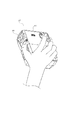
撮影時は、ディスクカバー511付近を手のひらで覆うようにし、人差し指をズームスイッチ近傍201に、又、親指を動画記録開始ボタン204近傍に各々添え、残りの中指、薬指、小指の3本は機器前方を掴むようにして本機101を把持して使用する。(図6)
前述のように動画記録ボタン204は、ディスク401と略同心円の曲面凹部上に配置されているので親指が自然な姿勢で乗り、無理なく動画記録ボタン204を操作することができる。また、ビデオカメラ101を把持した状態では機器前方の曲面凹部507a、509aにちょうど中指、薬指かかるため手に力が入りやすくホールド性が格段に向上する。
When shooting, cover the
As described above, since the moving
本実施例ではビデオカメラ本体の前後に設けた凹部に指を引っ掛けるように持つことで、安定してビデオカメラ本体を把持することが可能となっているが、さらにホールド性を高める為に、従来例にて説明したように機器の前方から後方へベルトを渡し、右手をベルトにくぐらせる構成とすることも当然可能である。 In this embodiment, it is possible to stably hold the video camera body by hooking the fingers in the recesses provided at the front and rear of the video camera body, but in order to further improve the holdability, As explained in the example, it is naturally possible to adopt a configuration in which the belt is passed from the front to the rear of the device and the right hand passes through the belt.
そして、撮像部302を被写体方向へ向けて本機101を構え、ビューファインダー303や液晶モニタ513を用いて画像を確認しながら撮影できる。又、撮像部302の上方に設置したマイクユニット508によって、周囲の音声を録音できる。
Then, the
101 ビデオカメラ本体
201 ズームスイッチ
202 静止画記録ボタン
203 スイッチユニット
204 動画記録開始ボタン
301 ディスク駆動装置
302 撮像部
303 ビューファインダー部
304 主制御基板
402 ターンテーブル
403 スピンドルモータ
408 光ピックアップ部
409 リードスクリュー
501 保持板金
503 リモコン受光素子
505 窓部材
506 プリント基板
507 外装カバー
508 マイクユニット
509 外装カバー
511 ディスクカバー
512 ヒンジ
513 液晶モニタユニット
514 バッテリーパック
DESCRIPTION OF
Claims (4)
Priority Applications (1)
| Application Number | Priority Date | Filing Date | Title |
|---|---|---|---|
| JP2005119595A JP2006303677A (en) | 2005-04-18 | 2005-04-18 | Image recording device |
Applications Claiming Priority (1)
| Application Number | Priority Date | Filing Date | Title |
|---|---|---|---|
| JP2005119595A JP2006303677A (en) | 2005-04-18 | 2005-04-18 | Image recording device |
Publications (1)
| Publication Number | Publication Date |
|---|---|
| JP2006303677A true JP2006303677A (en) | 2006-11-02 |
Family
ID=37471483
Family Applications (1)
| Application Number | Title | Priority Date | Filing Date |
|---|---|---|---|
| JP2005119595A Withdrawn JP2006303677A (en) | 2005-04-18 | 2005-04-18 | Image recording device |
Country Status (1)
| Country | Link |
|---|---|
| JP (1) | JP2006303677A (en) |
-
2005
- 2005-04-18 JP JP2005119595A patent/JP2006303677A/en not_active Withdrawn
Similar Documents
| Publication | Publication Date | Title |
|---|---|---|
| JP2005077574A (en) | Imaging apparatus | |
| JP2004007214A (en) | Image pickup unit | |
| JP2807616B2 (en) | Camera-integrated recording device with monitor | |
| WO2007077759A1 (en) | Imaging device | |
| JP4797955B2 (en) | Information recording / reproducing device | |
| JP2006303677A (en) | Image recording device | |
| US9179050B2 (en) | Electronic device with slidable display section | |
| JP3347048B2 (en) | Camera-integrated recording device with monitor | |
| JP2007049381A (en) | Photographing apparatus | |
| JP4207880B2 (en) | Waterproof electronic equipment | |
| JP2004179793A (en) | Image pickup apparatus | |
| JP2009300558A (en) | Imaging apparatus | |
| JP2766626B2 (en) | Camera-integrated recording device with monitor | |
| JP2001053994A (en) | Video camera | |
| JP2766625B2 (en) | Camera-integrated recording device with monitor | |
| JPH04114568A (en) | Vtr integrated camera | |
| JP2004180137A (en) | Image pickup apparatus | |
| JP4348541B2 (en) | Cradle equipment | |
| JP4645193B2 (en) | Imaging device | |
| JP2001053987A (en) | Camcorder | |
| JP3587732B2 (en) | Camera-integrated recording device with monitor | |
| JPH0537832A (en) | Image pickup recording and reproducing device | |
| JPH04114567A (en) | Vtr integrated camera | |
| JP2004023339A (en) | Camera | |
| JP2009253863A (en) | Cover device for storage medium, and recording and playback apparatus |
Legal Events
| Date | Code | Title | Description |
|---|---|---|---|
| A300 | Application deemed to be withdrawn because no request for examination was validly filed |
Free format text: JAPANESE INTERMEDIATE CODE: A300 Effective date: 20080701 |