JP2006218010A - Blood pump and dynamic pressure bearing - Google Patents
Blood pump and dynamic pressure bearing Download PDFInfo
- Publication number
- JP2006218010A JP2006218010A JP2005032890A JP2005032890A JP2006218010A JP 2006218010 A JP2006218010 A JP 2006218010A JP 2005032890 A JP2005032890 A JP 2005032890A JP 2005032890 A JP2005032890 A JP 2005032890A JP 2006218010 A JP2006218010 A JP 2006218010A
- Authority
- JP
- Japan
- Prior art keywords
- shaft
- bearing
- impeller
- blood
- blood pump
- Prior art date
- Legal status (The legal status is an assumption and is not a legal conclusion. Google has not performed a legal analysis and makes no representation as to the accuracy of the status listed.)
- Pending
Links
Images


Classifications
-
- F—MECHANICAL ENGINEERING; LIGHTING; HEATING; WEAPONS; BLASTING
- F04—POSITIVE - DISPLACEMENT MACHINES FOR LIQUIDS; PUMPS FOR LIQUIDS OR ELASTIC FLUIDS
- F04D—NON-POSITIVE-DISPLACEMENT PUMPS
- F04D13/00—Pumping installations or systems
- F04D13/02—Units comprising pumps and their driving means
- F04D13/021—Units comprising pumps and their driving means containing a coupling
- F04D13/024—Units comprising pumps and their driving means containing a coupling a magnetic coupling
- F04D13/026—Details of the bearings
-
- F—MECHANICAL ENGINEERING; LIGHTING; HEATING; WEAPONS; BLASTING
- F04—POSITIVE - DISPLACEMENT MACHINES FOR LIQUIDS; PUMPS FOR LIQUIDS OR ELASTIC FLUIDS
- F04D—NON-POSITIVE-DISPLACEMENT PUMPS
- F04D29/00—Details, component parts, or accessories
- F04D29/04—Shafts or bearings, or assemblies thereof
- F04D29/046—Bearings
Abstract
Description
本発明は、血液を送る血液ポンプ、特に遠心ポンプ、斜流ポンプ、軸流ポンプなどのターボポンプの形態を採る血液ポンプおよびこの血液ポンプに好適な動圧軸受に関する。 The present invention relates to a blood pump that sends blood, particularly a blood pump that takes the form of a turbo pump such as a centrifugal pump, a mixed flow pump, and an axial flow pump, and a hydrodynamic bearing suitable for the blood pump.
遠心ポンプなどのターボポンプが血液を送る血液ポンプとして使用されている。例えば、下記特許文献1には、遠心ポンプを用いた血液ポンプが開示されている。この文献に開示された血液ポンプは、ハウジングに固定されたシャフトに対し、インペラを回転可能に保持している。そして、インペラには永久磁石が埋め込まれ、ハウジングの外側に発生される回転磁界によりインペラが駆動されている。 A turbo pump such as a centrifugal pump is used as a blood pump for sending blood. For example, Patent Document 1 below discloses a blood pump using a centrifugal pump. The blood pump disclosed in this document holds an impeller rotatably with respect to a shaft fixed to a housing. A permanent magnet is embedded in the impeller, and the impeller is driven by a rotating magnetic field generated outside the housing.
血液ポンプにおいては、その流路において血液が滞留すると、凝集し、血栓の原因となる場合がある。また、流路に狭い部分があると、赤血球が損傷するという問題がある。インペラを支持する軸受部分は、間隔の狭い部分となり、上記の問題が生じやすい部分である。一方、軸受は、インペラの支持を確実に行うため、十分な支持力を得る必要があり、また耐久性、特に耐摩耗性が要求される。 In a blood pump, if blood stays in the flow path, it may aggregate and cause a thrombus. Further, if there is a narrow portion in the flow path, there is a problem that red blood cells are damaged. The bearing portion that supports the impeller is a portion having a narrow interval, and is likely to cause the above problem. On the other hand, since the bearing reliably supports the impeller, it is necessary to obtain a sufficient support force, and durability, particularly wear resistance, is required.
本発明は、血液の滞留が少なく、また赤血球の損傷を防止するのに有利な血液ポンプを提供する。 The present invention provides a blood pump that has low blood retention and is advantageous in preventing red blood cell damage.
本発明の血液ポンプは、インペラがハウジングに固定されたシャフトに支持されており、このインペラに設けられた軸受の軸直交断面を多角形としている。シャフトの断面は円形であり、軸直交断面において軸受の一辺とシャフトの接触点は一点となり、一方、多角形の頂点の周辺は、十分広い流路が確保される。軸受の断面形状は、三角形とすることができる。さらに、軸受は、軸方向に離れた2カ所に設け、この間の空間は広い流路を確保するようにできる。 In the blood pump of the present invention, an impeller is supported by a shaft fixed to a housing, and a shaft orthogonal cross section of a bearing provided in the impeller is polygonal. The cross section of the shaft is circular, and in the cross section perpendicular to the axis, one side of the bearing and the contact point of the shaft become one point, while a sufficiently wide flow path is secured around the apex of the polygon. The cross-sectional shape of the bearing can be a triangle. Further, the bearings can be provided at two locations separated in the axial direction, and a space between them can be secured.
また、本発明の他の態様である動圧軸受は、断面が円の支持体を半径方向において支持する軸受であり、この軸受の軸直交断面を多角形としている。 A hydrodynamic bearing according to another aspect of the present invention is a bearing that supports a support having a circular cross section in the radial direction, and the axial orthogonal cross section of the bearing is a polygon.
以下、本発明の実施形態を、図面に従って説明する。図1は、本実施形態の血液ポンプ10の概略構成を示す断面図である。ハウジング12は、概略円筒形状を有し、円筒の軸に沿って吸込管14が、また側方には吐出管16が設けられている。ハウジング12の、吸込管14が設けられた面と反対側の面である底面には、ハウジングの中心軸に同軸にシャフト18が立設されている。ハウジング12の内部には、インペラ20が収容され、シャフト18に回転可能に支持されている。インペラ20は、円板または平たい円柱形状のインペラ本体22と、この本体の吸込管14側の面に立設される羽根24を含む。インペラ本体22の中心には、シャフト18との間に十分な間隔が形成される内径を有する中心孔26が形成され、さらに中心孔26の両端付近に軸受板28,30が配置されている。軸受板28,30は、その中心に軸受孔を有し、ここにシャフト18が貫通し、シャフト18に対してインペラ20が支持される。軸受の構造、すなわちシャフト18と軸受板28の詳細な構造については、後述する。
Hereinafter, embodiments of the present invention will be described with reference to the drawings. FIG. 1 is a cross-sectional view showing a schematic configuration of a
インペラ本体22の外周近傍には、永久磁石32が複数個埋め込まれて配置されている。ハウジング12の外側には、モータ34により回転される回転駆動部36が配置されている。回転駆動部36は、インペラ内の永久磁石32に半径方向に対向する位置に配置された永久磁石38を有し、対向する永久磁石32と永久磁石38とで磁気結合が形成される。モータ34を回転すると回転駆動部36が回転し、磁気結合によってインペラ20に回転力が伝達され、インペラ20が回転する。回転するインペラの羽根24は、ハウジング12内の血液に周方向および半径方向外側に向けて速度を与え、これにより血液が吐出管16より送り出される。また、インペラ20の中心付近においては、圧力が低下し、吸込管14より新たな血液が導入される。
A plurality of
羽根24により速度が与えられた血液の一部は、インペラ20の外周とハウジング12の間の隙間を通って、インペラ20の背面(図中下側の面)側に流れる。背面側の血液は、中心に向かって流れ、軸受板30とシャフト18の隙間と通過して、中心孔26内を流れ、更に軸受板28とシャフト18の隙間を通って、インペラ20の前面側に達する。
A part of the blood given speed by the
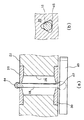
図2は、シャフト18にインペラ20を支持する軸受構造の詳細を示す図である。(a)は中心軸を含む平面における断面図、(b)は軸受部分の軸直交断面図である。シャフト18は、ハウジング12に埋め込まれた板形状のシャフトベース40より立設して、一体に形成されている。シャフト18の根元の部分42、すなわちシャフト18とシャフトベース40が接合する部分の表面形状は、球面の一部となっている。また、シャフト18の先端には、係止ボール44が固定されている。上部の軸受板28と係止ボール44および下部の軸受板30とシャフトの根元部分42が軸方向に当接して、インペラ20の軸方向の位置決めが達成される。なお、組立は、ハウジング12に固定されたシャフト18に、軸受板28,30があらかじめ固定されたインペラ20を装着し、その後シャフト18の先端に係止ボール44を固定して行われる。
FIG. 2 is a diagram showing details of the bearing structure that supports the
図2(b)に示すように、軸受板28に形成された、シャフト18が貫通する軸受孔46は、三角形であり、その各辺がシャフト18とほぼ接触する。より詳細には、通常のジャーナル軸受と同様、シャフトと軸受は、わずかなクリアランスを有している。シャフト18と軸受板28のクリアランスは、各辺の中央付近で小さく、三角形の各頂点に向かって徐々に大きくなり、くさび形状を呈している。このため、インペラ20が回転すると、回転に伴う血液の周方向流れが形成され、くさび形状の部分に送り込まれ、くさび効果による動圧が発生し、シャフト18がクリアランスをもった状態で軸受板28に支持される。軸受孔46の各頂点付近においては、大きな隙間が形成されており、軸方向の血液の流れを阻害しないようにしている。これによりインペラ背面側から中心孔26を通過して前面側に還流する血液の流量が確保され、滞留による血液凝固を防止することができる。軸受板28に形成された軸受孔46について説明したが、軸受板30にも同様の軸受孔が形成されている。
As shown in FIG. 2B, the
このように、三角形の軸受孔の各辺、すなわち直線部分と円断面のシャフトを対向させるようにしたことで、くさび効果による動圧を発生し、また、頂点部分において、軸方向の流れが確保される。したがって、軸受の孔の形状は三角形に限定されず、孔の直線部分とシャフトが軸直交断面において点接触し、接点から離れた部分に軸方向の流路が確保される形状であれば、他の形状、例えば四角形以上の多角形とすることが可能であることが理解される。なお、図示した三角形の頂点を円弧で形成したのは、加工性を考慮したためである In this way, by making each side of the triangular bearing hole, that is, the straight part and the shaft of the circular section face each other, dynamic pressure due to the wedge effect is generated, and axial flow is secured at the apex part. Is done. Therefore, the shape of the hole in the bearing is not limited to a triangle, and any other shape can be used as long as the linear portion of the hole and the shaft are in point contact with each other in a cross section perpendicular to the axis and an axial flow path is secured in a portion away from the contact point. It is understood that the shape can be, for example, a quadrilateral or more polygon. In addition, the reason why the vertices of the illustrated triangle are formed by arcs is that workability is taken into consideration.
図2(a)に示すように、軸受板28,30は、軸方向に離れて2カ所、特にインペラ本体22の両端に設けられ、その厚さは極薄い。軸受板28,30の間の中心孔26の内径は、シャフト18との間に十分な幅の流路を形成する幅となっている。このように、シャフト18にインペラ20を支持するための軸受において、実際に狭い隙間となる部分は、軸受板28,30の軸受孔の各辺の中点付近のごく一部であり、その他の部分においては、十分な幅、特に赤血球などの血液成分が損傷を受けない十分な幅、隙間が確保される。
As shown in FIG. 2A, the
図3は、軸受周囲の構成の具体的な寸法の例を示す図である。中心孔26の内径は5mmとなっている。シャフト18と軸受板28,30の材質としては、例えば、シャフトをチタン、軸受板をポリエチレンなどの樹脂とする構成、双方ともステンレス鋼にする構成、さらに双方ともステンレス鋼にダイアモンドライクカーボン(DLC)のコーティングをする構成、シャフトをDLCコーティングしたステンレス鋼、軸受板28,30をポリエチレンの樹脂などとする構成などを採ることができる。DLCコーティングは、その表面が平滑であり、摩擦耐摩耗性を向上させることができる。
FIG. 3 is a diagram showing an example of specific dimensions of the configuration around the bearing. The inner diameter of the
10 血液ポンプ、12 ハウジング、18 シャフト、20 インペラ、22 インペラ本体、26 中心孔、28,30 軸受板、44 係止ボール、46 軸受孔。 10 blood pump, 12 housing, 18 shaft, 20 impeller, 22 impeller body, 26 center hole, 28, 30 bearing plate, 44 locking ball, 46 bearing hole.
Claims (5)
インペラには、当該インペラをシャフトに対し回転可能に支持し、軸直交断面の形状が多角形であり、
この軸受の位置におけるシャフトの軸直交断面は円である、
血液ポンプ。 A blood pump for delivering blood by an impeller that is supported by a shaft fixed to a housing and rotates;
The impeller supports the impeller so as to be rotatable with respect to the shaft, and the shape of the cross section perpendicular to the axis is a polygon.
The axial cross section of the shaft at the position of this bearing is a circle,
Blood pump.
The hydrodynamic bearing according to claim 4, wherein the cross-sectional shape is a triangle.
Priority Applications (1)
| Application Number | Priority Date | Filing Date | Title |
|---|---|---|---|
| JP2005032890A JP2006218010A (en) | 2005-02-09 | 2005-02-09 | Blood pump and dynamic pressure bearing |
Applications Claiming Priority (1)
| Application Number | Priority Date | Filing Date | Title |
|---|---|---|---|
| JP2005032890A JP2006218010A (en) | 2005-02-09 | 2005-02-09 | Blood pump and dynamic pressure bearing |
Publications (2)
| Publication Number | Publication Date |
|---|---|
| JP2006218010A true JP2006218010A (en) | 2006-08-24 |
| JP2006218010A5 JP2006218010A5 (en) | 2007-11-29 |
Family
ID=36980714
Family Applications (1)
| Application Number | Title | Priority Date | Filing Date |
|---|---|---|---|
| JP2005032890A Pending JP2006218010A (en) | 2005-02-09 | 2005-02-09 | Blood pump and dynamic pressure bearing |
Country Status (1)
| Country | Link |
|---|---|
| JP (1) | JP2006218010A (en) |
Cited By (8)
| Publication number | Priority date | Publication date | Assignee | Title |
|---|---|---|---|---|
| WO2008093594A1 (en) * | 2007-01-30 | 2008-08-07 | Jms Co., Ltd. | Turbo type blood pump |
| JP2012055485A (en) * | 2010-09-08 | 2012-03-22 | Terumo Corp | Centrifugal blood pump and centrifugal blood pump device |
| JP2012161525A (en) * | 2011-02-08 | 2012-08-30 | Terumo Corp | Centrifugal blood pump and centrifugal blood pump device |
| WO2012115155A1 (en) * | 2011-02-24 | 2012-08-30 | 株式会社ジェイ・エム・エス | Turbo blood pump |
| JP2013053591A (en) * | 2011-09-05 | 2013-03-21 | Terumo Corp | Centrifugal pump |
| WO2013118419A1 (en) | 2012-02-06 | 2013-08-15 | メドテックハート株式会社 | Blood pump |
| JP2016052581A (en) * | 2011-08-29 | 2016-04-14 | ミネトロニクス, インコーポレイテッド | Expandable vas pump |
| CN112237680A (en) * | 2020-09-15 | 2021-01-19 | 安徽通灵仿生科技有限公司 | Axial-flow type heart auxiliary device with heparin coating and hydrophobic protection |
Citations (6)
| Publication number | Priority date | Publication date | Assignee | Title |
|---|---|---|---|---|
| JPH03107612A (en) * | 1989-09-20 | 1991-05-08 | Sankyo Seiki Mfg Co Ltd | Oil-impregnated sintered bearing |
| JP2001061957A (en) * | 1999-08-25 | 2001-03-13 | Nikkiso Co Ltd | Blood pump |
| JP2001065548A (en) * | 1999-08-30 | 2001-03-16 | Nakamasa Takeno | Non-cylindrical plain bearing unit |
| JP2001065546A (en) * | 1999-08-27 | 2001-03-16 | Okuma Corp | Dynamic pressure bearing structure |
| JP2001518161A (en) * | 1997-03-19 | 2001-10-09 | ザ クリーブランド クリニック ファウンデーション | Rotary dynamic pump with non-circular fluid bearing journal |
| JP2004052845A (en) * | 2002-07-17 | 2004-02-19 | Fujikura Ltd | Bearing structure and motor using the same |
-
2005
- 2005-02-09 JP JP2005032890A patent/JP2006218010A/en active Pending
Patent Citations (6)
| Publication number | Priority date | Publication date | Assignee | Title |
|---|---|---|---|---|
| JPH03107612A (en) * | 1989-09-20 | 1991-05-08 | Sankyo Seiki Mfg Co Ltd | Oil-impregnated sintered bearing |
| JP2001518161A (en) * | 1997-03-19 | 2001-10-09 | ザ クリーブランド クリニック ファウンデーション | Rotary dynamic pump with non-circular fluid bearing journal |
| JP2001061957A (en) * | 1999-08-25 | 2001-03-13 | Nikkiso Co Ltd | Blood pump |
| JP2001065546A (en) * | 1999-08-27 | 2001-03-16 | Okuma Corp | Dynamic pressure bearing structure |
| JP2001065548A (en) * | 1999-08-30 | 2001-03-16 | Nakamasa Takeno | Non-cylindrical plain bearing unit |
| JP2004052845A (en) * | 2002-07-17 | 2004-02-19 | Fujikura Ltd | Bearing structure and motor using the same |
Cited By (17)
| Publication number | Priority date | Publication date | Assignee | Title |
|---|---|---|---|---|
| US8398382B2 (en) | 2007-01-30 | 2013-03-19 | Jms Co., Ltd. | Turbo type blood pump |
| JP2008183229A (en) * | 2007-01-30 | 2008-08-14 | Jms Co Ltd | Turbo type blood pump |
| JP4655231B2 (en) * | 2007-01-30 | 2011-03-23 | 株式会社ジェイ・エム・エス | Turbo blood pump |
| KR101099832B1 (en) | 2007-01-30 | 2011-12-27 | 가부시끼가이샤 제이엠에스 | Turbo type blood pump |
| WO2008093594A1 (en) * | 2007-01-30 | 2008-08-07 | Jms Co., Ltd. | Turbo type blood pump |
| JP2012055485A (en) * | 2010-09-08 | 2012-03-22 | Terumo Corp | Centrifugal blood pump and centrifugal blood pump device |
| JP2012161525A (en) * | 2011-02-08 | 2012-08-30 | Terumo Corp | Centrifugal blood pump and centrifugal blood pump device |
| JP5590213B2 (en) * | 2011-02-24 | 2014-09-17 | 株式会社ジェイ・エム・エス | Turbo blood pump |
| JPWO2012115155A1 (en) * | 2011-02-24 | 2014-07-07 | 株式会社ジェイ・エム・エス | Turbo blood pump |
| WO2012115155A1 (en) * | 2011-02-24 | 2012-08-30 | 株式会社ジェイ・エム・エス | Turbo blood pump |
| JP2016052581A (en) * | 2011-08-29 | 2016-04-14 | ミネトロニクス, インコーポレイテッド | Expandable vas pump |
| JP2013053591A (en) * | 2011-09-05 | 2013-03-21 | Terumo Corp | Centrifugal pump |
| WO2013118419A1 (en) | 2012-02-06 | 2013-08-15 | メドテックハート株式会社 | Blood pump |
| JP2013160136A (en) * | 2012-02-06 | 2013-08-19 | Medtech Heart Inc | Blood pump |
| US9592326B2 (en) | 2012-02-06 | 2017-03-14 | Medtech Heart Inc. | Blood pump |
| CN112237680A (en) * | 2020-09-15 | 2021-01-19 | 安徽通灵仿生科技有限公司 | Axial-flow type heart auxiliary device with heparin coating and hydrophobic protection |
| CN112237680B (en) * | 2020-09-15 | 2023-08-25 | 安徽通灵仿生科技有限公司 | Axial-flow heart auxiliary device with heparin coating and hydrophobic protection |
Similar Documents
| Publication | Publication Date | Title |
|---|---|---|
| JP2006218010A (en) | Blood pump and dynamic pressure bearing | |
| JP4209412B2 (en) | Artificial heart pump | |
| KR102309738B1 (en) | Centrifugal blood pump | |
| JP4176753B2 (en) | Artificial heart pump | |
| US20020031436A1 (en) | Turbo blood pump | |
| JP2015532146A5 (en) | ||
| JP2008528870A (en) | Rotating device | |
| CA2676800A1 (en) | Turbo type blood pump | |
| JP2004346925A (en) | Device for securing noncontact of rotary part in noncontact pump | |
| JP2009254436A (en) | Artificial heart pump equipped with dynamic pressure bearing | |
| WO2001021969A1 (en) | Dynamic pressure bearing with improved starting characteristics | |
| JP4611364B2 (en) | Artificial heart pump | |
| JP4611365B2 (en) | Artificial heart pump | |
| JP2013155868A (en) | Spindle motor | |
| JP4078245B2 (en) | Artificial heart pump | |
| JP2008121686A (en) | Artificial heart pump | |
| JP4523961B2 (en) | Artificial heart pump | |
| JP4512150B2 (en) | Artificial heart pump | |
| JP4485379B2 (en) | Bearing and blood pump | |
| JP2004073400A (en) | Centrifugal blood pump | |
| JP2005256706A (en) | Elongated centrifugal fan | |
| JP2007303316A (en) | Motor pump | |
| JP2015155682A (en) | Noncontact bearing pump | |
| JP2007325329A (en) | Axial gap type motor and fuel pump | |
| JP4325763B2 (en) | Pump bearing washer |
Legal Events
| Date | Code | Title | Description |
|---|---|---|---|
| A521 | Written amendment |
Free format text: JAPANESE INTERMEDIATE CODE: A523 Effective date: 20071017 |
|
| A621 | Written request for application examination |
Free format text: JAPANESE INTERMEDIATE CODE: A621 Effective date: 20071017 |
|
| A977 | Report on retrieval |
Free format text: JAPANESE INTERMEDIATE CODE: A971007 Effective date: 20090622 |
|
| A131 | Notification of reasons for refusal |
Free format text: JAPANESE INTERMEDIATE CODE: A131 Effective date: 20090630 |
|
| A02 | Decision of refusal |
Free format text: JAPANESE INTERMEDIATE CODE: A02 Effective date: 20091027 |