JP2006207614A - Tension adjusting device for belt - Google Patents
Tension adjusting device for belt Download PDFInfo
- Publication number
- JP2006207614A JP2006207614A JP2005016831A JP2005016831A JP2006207614A JP 2006207614 A JP2006207614 A JP 2006207614A JP 2005016831 A JP2005016831 A JP 2005016831A JP 2005016831 A JP2005016831 A JP 2005016831A JP 2006207614 A JP2006207614 A JP 2006207614A
- Authority
- JP
- Japan
- Prior art keywords
- spherical sliding
- sliding surface
- auto tensioner
- hydraulic auto
- hydraulic
- Prior art date
- Legal status (The legal status is an assumption and is not a legal conclusion. Google has not performed a legal analysis and makes no representation as to the accuracy of the status listed.)
- Pending
Links
Images


Abstract
Description
この発明は、主として、オルタネータ等の自動車補機を駆動するベルトの張力調整装置に関するものである。 The present invention mainly relates to a belt tension adjusting device for driving an automobile auxiliary machine such as an alternator.
テンションプーリを支持するプーリアームをエンジンに揺動自在に取付け、そのプーリアームに連結した油圧式オートテンショナによってテンションプーリの外周にかかるベルトの張力変化を吸収してベルトの張力を一定に保持するようにしたベルトの張力調整装置は特許文献1に記載されている。
A pulley arm that supports the tension pulley is swingably attached to the engine, and the belt tension on the outer periphery of the tension pulley is absorbed by a hydraulic auto tensioner connected to the pulley arm so that the belt tension is kept constant. A belt tension adjusting device is described in
ここで、油圧式オートテンショナは、作動油が充填されたシリンダの上部開口をオイルシール等のシール部材で密閉し、そのシール部材をスライド自在に貫通するロッドにリターンスプリングの押圧力を付与して外方向への突出性を付与し、ベルトからプーリアームを介してロッドに負荷される押し込み力をシリンダ内部に組込まれた油圧ダンパにより緩衝するようにしている。
ところで、上記従来のベルトの張力調整装置においては、油圧式オートテンショナのロッドの上端部およびシリンダの下端部のそれぞれに連結片を設け、その連結片に両側面に貫通する軸受嵌合孔を形成し、その軸受嵌合孔に嵌合された筒状の滑り軸受内にボルトを挿入し、各ボルトの締付けによってロッド側連結片をプーリアームに連結し、かつシリンダ側連結片をエンジンに連結する構成であるため、油圧式オートテンショナはエンジンのアーム取付面やテンショナ取付面の精度の影響を受け易い。ここで、取付面の面精度が悪い場合、プーリアームと油圧式オートテンショナの相互間に傾きが生じるという、ミスアライミントが発生し、油圧式オートテンショナに偏荷重が負荷されてロッドとシリンダの相対的な伸縮が阻害され、油圧式オートテンショナの機能を損ない、耐久性を低下させることになる。 By the way, in the conventional belt tension adjusting device, a connecting piece is provided on each of the upper end of the rod of the hydraulic auto tensioner and the lower end of the cylinder, and a bearing fitting hole penetrating the both sides is formed in the connecting piece. The bolt is inserted into the cylindrical slide bearing fitted in the bearing fitting hole, the rod side connecting piece is connected to the pulley arm by tightening each bolt, and the cylinder side connecting piece is connected to the engine. Therefore, the hydraulic auto tensioner is easily affected by the accuracy of the engine arm mounting surface and the tensioner mounting surface. Here, if the surface accuracy of the mounting surface is poor, a misalignment occurs in which an inclination occurs between the pulley arm and the hydraulic auto tensioner, and an offset load is applied to the hydraulic auto tensioner, causing the relative relationship between the rod and the cylinder. The mechanical expansion and contraction is hindered, impairing the function of the hydraulic auto tensioner and reducing the durability.
また、油圧式オートテンショナに負荷される偏荷重によって滑り軸受と軸受嵌合孔の接触部に偏摩耗が生じ易くなる。 Further, uneven wear is likely to occur at the contact portion between the sliding bearing and the bearing fitting hole due to the uneven load applied to the hydraulic auto tensioner.
このため、エンジンのアーム取付面やテンショナ取付面には精度の高い加工が要求され、加工に手間がかかり、加工コストも高くなるという不都合がある。 For this reason, high-precision processing is required for the arm mounting surface and the tensioner mounting surface of the engine, and there is a disadvantage that processing takes time and processing cost increases.
また、油圧式オートテンショナは、通常、エンジンカバーの外部に取付けられるため、泥水等がかかると、その泥水が滑り軸受と軸受嵌合孔の接触部に浸入し易く、その泥水の浸入によって軸受寿命が著しく低下するという問題がある。 Also, hydraulic auto tensioners are usually mounted outside the engine cover, so if muddy water or the like is applied, the muddy water can easily enter the contact portion between the slide bearing and the bearing fitting hole. There is a problem that the remarkably decreases.
この発明の課題は、油圧式オートテンショナの取付け時におけるミスアライメントを吸収することができるようにして、油圧式オートテンショナの機能および耐久性の低下を抑制することができるようにしたベルトの張力調整装置を提供することである。 An object of the present invention is to adjust the tension of a belt that can absorb a misalignment at the time of mounting a hydraulic auto tensioner and suppress a decrease in the function and durability of the hydraulic auto tensioner. Is to provide a device.
上記の課題を解決するために、この発明においては、テンションプーリを支持する揺動可能なプーリアームに一端部が連結され、他端部がエンジン側の支点部材に揺動自在に連結された油圧式オートテンショナによりテンションプーリにかけ渡されたベルトの張力変化を吸収してベルトの張力を一定に保つようにしたベルトの張力調整装置において、前記油圧式オートテンショナとプーリアームの連結部での接触および油圧式オートテンショナと支点部材の連結部での接触を油圧式オートテンショナの中心軸上に中心を有する凸形の球面状滑り面と凹形の球面状滑り面の球面接触とした構成を採用したのである。 In order to solve the above-mentioned problems, in the present invention, one end is connected to a swingable pulley arm that supports a tension pulley, and the other end is swingably connected to a fulcrum member on the engine side. In the belt tension adjusting device that absorbs a change in the tension of the belt passed over the tension pulley by the auto tensioner and keeps the tension of the belt constant, contact at the connecting portion of the hydraulic auto tensioner and the pulley arm and a hydraulic type The contact at the connecting portion between the auto tensioner and the fulcrum member is a spherical contact between a convex spherical sliding surface centered on the central axis of the hydraulic auto tensioner and a concave spherical sliding surface. .
ここで、油圧式オートテンショナとして、内部に作動油が充填されたシリンダと、そのシリンダの上端開口を密封するシール部材と、そのシール部材をスライド自在に貫通するロッドと、そのロッドに外方向への突出性を付与するリターンスプリングと、前記シリンダ内に組込まれてロッドに付与される押し込み力を緩衝する油圧ダンパとを有し、前記シリンダの下端部およびロッドの上端部に凸形球面状滑り面と凹形球面状滑り面の一方が設けられた構成から成るものを採用することができる。 Here, as a hydraulic auto tensioner, a cylinder filled with hydraulic oil, a seal member that seals the upper end opening of the cylinder, a rod that slidably passes through the seal member, and an outward direction to the rod A return spring that imparts a projecting property of the cylinder, and a hydraulic damper that is incorporated in the cylinder and cushions the pushing force applied to the rod, and has a convex spherical slip at the lower end of the cylinder and the upper end of the rod. It is possible to employ a construction in which one of a surface and a concave spherical sliding surface is provided.
球面状滑り面の採用において、凹形球面状滑り面が凸形球面状滑り面上に位置する配置とすることにより、凹形球面状滑り面と凸形球面状滑り面の接触部に泥水が浸入するのを防止することができ、連結部の耐久性の低下を抑制することができる。 In the adoption of the spherical sliding surface, the concave spherical sliding surface is positioned on the convex spherical sliding surface, so that muddy water is brought into contact with the concave spherical sliding surface and the convex spherical sliding surface. Intrusion can be prevented, and a decrease in durability of the connecting portion can be suppressed.
また、凹形球面状滑り面を自己潤滑性の被膜により形成すると、その凹形球面状滑り面と凸形球面状滑り面の接触部での滑りを円滑に行なわせることができる。 In addition, when the concave spherical sliding surface is formed of a self-lubricating film, sliding at the contact portion between the concave spherical sliding surface and the convex spherical sliding surface can be performed smoothly.
上記のように、油圧式オートテンショナのエンジンおよびプーリアームに対する連結部に凸形球面状滑り面とこれに面接触する凹形球面状滑り面を設けることにより、油圧式オートテンショナの取付け時に、その油圧式オートテンショナが傾くなどのミスアライメントが生じると、凸形球面状滑り面と凹形球面状滑り面の接触部で滑りが生じてそのミスアライメントを吸収する。このため、油圧式オートテンショナに偏荷重が作用することはなく、油圧式オートテンショナの機能および耐久性の低下を抑制することができる。 As described above, by providing a convex spherical sliding surface and a concave spherical sliding surface in surface contact with the connecting portion of the hydraulic auto tensioner to the engine and the pulley arm, the hydraulic pressure is increased when the hydraulic auto tensioner is mounted. When misalignment such as tilting of the automatic tensioner occurs, slip occurs at the contact portion between the convex spherical sliding surface and the concave spherical sliding surface to absorb the misalignment. For this reason, an unbalanced load does not act on the hydraulic auto tensioner, and a decrease in the function and durability of the hydraulic auto tensioner can be suppressed.
また、油圧式オートテンショナとエンジンの連結部に偏荷重が作用するのを防止することができるため、上記連結部の耐久性の向上を図ることができる。 Further, since it is possible to prevent an uneven load from acting on the connecting portion between the hydraulic auto tensioner and the engine, the durability of the connecting portion can be improved.
さらに、エンジンへの取付けに精度が要求されず、取付面の加工が容易となり、加工コストの低減を図ることができる。 Further, accuracy is not required for attachment to the engine, the attachment surface can be easily processed, and the processing cost can be reduced.
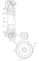
以下、この発明の実施の形態を図面に基づいて説明する。図1および図2にこの発明に係るベルトの張力調整装置の第1の実施形態を示す。図示のように、プーリアーム1はエンジンAにねじ込まれた支点軸2によって上端部が支持され、その支点軸2を中心として揺動自在とされている。
Hereinafter, embodiments of the present invention will be described with reference to the drawings. 1 and 2 show a belt tension adjusting apparatus according to a first embodiment of the present invention. As shown in the drawing, the
プーリアーム1の揺動側端部となる下端部にはテンションプーリ3が回転自在に支持されている。また、プーリアーム1は揺動中心側の端部に受圧片部4を有し、その受圧片部4の先端部上面に支持片5が設けられ、この支持片5にねじ込まれる取付ボルト6の締付けによって受圧片部4の先端部上に設けられたテンショナ連結子7が固定されている。このテンショナ連結子7は凸形の球面状滑り面7aを外周に有している。
A
上記受圧片部4の上方には支点部材としての連結ピース8が設けられている。連結ピース8はエンジンAにねじ込まれるボルト9の締付けによってエンジンAに固定され、下面には凹形の球面状滑り面10が設けられている。この凹形球面状滑り面10は自己潤滑性を有する被膜11によって形成されている。
A connecting
連結ピース8とその下方に設けられた前記受圧片部4との間にはテンションプーリ3がベルトBを押圧する方向にプーリアーム1を付勢する油圧式オートテンショナ20が設けられている。
Between the connecting
油圧式オートテンショナ20は作動油が充填されたシリンダ21と、そのシリンダ21の上部開口を密閉するシール部材22と、そのシール部材22をスライド自在に貫通するロッド23と、そのロッド23に外方向への突出性を付与するリターンスプリング24と、ロッド23とシリンダ21とに収縮させる方向の押し込み力が負荷されたときその押し込み力を緩衝する油圧ダンパ25とを有している。
The
シリンダ21はアルミ合金から成り、内部に鋼製の底付スリーブ26が嵌合されている。また、シリンダ21は、油圧式オートテンショナ20の中心軸上に中心をもつ凹形の球面状滑り面27を下端に有し、その凹形球面状滑り面27は自己潤滑性を有する被膜28によって形成されている。この凹形球面状滑り面27はテンショナ連結子7の球面状滑り面7aの1/2円以上にわたって面接触している。
The
ロッド23は上端部にばね座29を有し、そのばね座29とシリンダ21の下端部外周に設けられたばね座30間にリターンスプリング24が組込まれている。
The
ロッド23に設けられたばね座29の下面には円筒状のカバー31が設けられ、そのカバー31はシリンダ21の外周上部を覆い、シリンダ21内にダストや泥水が浸入するのを防止している。また、ばね座29の上面には半球状の突部32が設けられ、その突部32の外周に油圧式オートテンショナ20の中心軸上に中心をもつ凸形の球面状滑り面33が形成されている。この凸形球面状滑り面33は連結ピース8の下面に設けられた前記凹形の球面状滑り面10と面接触している。
A
油圧ダンパ25は、ロッド23の下端部にスリーブ26の内径面に沿って摺動可能なプランジャ34を接続し、そのプランジャ34によってシリンダ21の内部を圧力室35とリザーバ室36に仕切り、プランジャ34にはその下方の圧力室35と上方のリザーバ室36とを連通する通路37を設け、その通路37の圧力室35側の開口部にチェックバルブ38を設け、ロッド23とシリンダ21とに収縮される方向の押し込み力が負荷されたときチェックバルブ38で通路37を閉じ、圧力室35内に封入された作動油で上記押し込み力を緩衝するようにしている。
The
なお、39はプランジャ34をロッド23の下端部に押し付けるスプリングを示す。
実施の形態で示すベルトの張力調整装置は上記の構造から成り、ベルトBがトルク変動などによって振動し、そのベルトBに弛みが生じると、リターンスプリング24の押圧力によりシリンダ21が下降してプーリアーム1を押圧する。このため、プーリアーム1は支点軸2を中心に揺動し、テンションプーリ3がベルトBを押圧してベルトBの弛みを吸収する。
The belt tension adjusting device shown in the embodiment has the above-described structure. When the belt B vibrates due to torque fluctuation or the like and the belt B is slackened, the
このとき、圧力室35の容積が拡大して圧力が低下し、チェックバルブ38は通路37を開放するため、リザーバ室36の作動油は通路37から圧力室35内に流入し、シリンダ21はスムーズに下方向に移動してベルトBの弛みを直ちに吸収する。
At this time, the volume of the
一方、ベルトBの張力が増大すると、ベルトBからテンションプーリ3およびプーリアーム1を介してシリンダ21に押し込み力が負荷される。
On the other hand, when the tension of the belt B increases, a pushing force is applied from the belt B to the
このとき、圧力室35内の圧力がリザーバ室36内の圧力より高くなるため、チェックバルブ38は通路37を閉じ、圧力室35内に封入された作動油によって押し込み力が緩衝される。
At this time, since the pressure in the
上記押し込み力がリターンスプリング24の弾性力より強い場合、圧力室35内の作動油はスリーブ26とプランジャ34の摺動面間に形成された微小なリークすきまからリザーバ室36内に流れ、シリンダ21はリターンスプリング24の弾性力と押し込み力とが釣り合う位置までゆっくりと上昇する。
When the pushing force is stronger than the elastic force of the
油圧式オートテンショナ20の組付けに際し、その油圧式オートテンショナ20はエンジンAのアーム取付面およびピース取付面の面精度の影響を受け易く、上記各取付面の面精度が悪い場合、油圧式オートテンショナ20とプーリアーム1および連結ピース8の相互間に傾きが生じるというミスアライメントが発生する。
When the
このとき、プーリアーム1とシリンダ21の連結部では、テンショナ連結子7の凸形球面状滑り面7aとシリンダ21の凹形球面状滑り面27の球面接触であり、また、ロッド23と連結ピース8の連結部では連結ピース8の凹形球面状滑り面10と突部32の凸形球面状滑り面33の球面接触であるため、油圧式オートテンショナ20の組付けにミスアライメントが発生すると、各球面状滑り面の接触部で滑りが生じて上記ミスアライメントを吸収する。
At this time, the connecting portion between the
このため、油圧式オートテンショナ20に偏荷重が作用することはなく、油圧式オートテンショナ20を高精度に機能させることができると共に耐久性の低下を抑制することができる。
For this reason, an unbalanced load does not act on the
また、プーリアーム1とシリンダ21との連結部およびロッド23と連結ピース8の連結部においてミスアライメントを吸収することができるため、エンジンAのピース取付面およびアーム取付面に精度が要求されない。このため、取付面の加工が容易となり、加工コストの低減を図ることができる。
Further, since misalignment can be absorbed in the connecting portion between the
さらに、シリンダ21とプーリアーム1の連結部およびロッド23と連結ピース8の連結部に設けられた凹形の球面状滑り面27,10と凸形の球面状滑り面7a,33は、凸形の球面状滑り面7a,33上に凹形の球面状滑り面27,10が位置して凸形の球面状滑り面7a,33の外周上部を覆っているため、球面状滑り面7aと27および10と33の接触部に泥水等が浸入し難く、各連結部の耐久性の低下を抑制することができる。
Furthermore, the concave spherical sliding
第1の実施形態では、シリンダ21の下端部をその下方に設けられたプーリアーム1に連結すると共に、ロッド23の上端部をその上方に設けられた連結ピース8に連結するようにしたが、図3および図4に示すように、ロッド23の上端部をその上方に設けられたプーリアーム1に連結し、かつシリンダ21の下端部をその下方に設けられた支点部材としての支持ピン40に連結してテンションプーリ3の外周上部にかかるベルトBの張力を一定に保つようにしてもよい。
In the first embodiment, the lower end portion of the
この場合、プーリアーム1はその下端部を支点軸2で支持して揺動自在に支持し、その揺動中心側の端部一側から側方に張り出す受圧片部4の先端部下面に凹形の球面状滑り面41を形成し、この球面状滑り面41にロッド23の上端部に設けられた突部32の凸形の球面状滑り面33を面接触させる。
In this case, the lower end of the
また、支持ピン40は、エンジンAに対してねじ止めし、その支持ピン40の先端部に凸形の球面状滑り面42を設け、その球面状滑り面42をシリンダ21の下端に設けられた凹形の球面状滑り面27に面接触させるようにする。
Further, the
図3および図4に示す第2の実施形態においても、凹形の球面状滑り面41と凸形の球面状滑り面33の接触部での滑りおよび凹形の球面状滑り面27と凸形の球面状滑り面42の接触部での滑りによって油圧式オートテンショナ20の組付け時に発生するミスアライメントを吸収することができる。
Also in the second embodiment shown in FIG. 3 and FIG. 4, sliding at the contact portion between the concave spherical sliding
A エンジン
B ベルト
1 プーリアーム
3 テンションプーリ
7a 凸形球面状滑り面
8 連結ピース(支点部材)
10 凹形球面状滑り面
20 油圧式オートテンショナ
21 シリンダ
22 シール部材
23 ロッド
24 リターンスプリング
25 油圧ダンパ
27 凹形球面状滑り面
33 凸形球面状滑り面
40 支持ピン(支点部材)
41 凹形球面状滑り面
42 凸形球面状滑り面
A
DESCRIPTION OF
41 Concave spherical sliding
Claims (4)
Priority Applications (1)
| Application Number | Priority Date | Filing Date | Title |
|---|---|---|---|
| JP2005016831A JP2006207614A (en) | 2005-01-25 | 2005-01-25 | Tension adjusting device for belt |
Applications Claiming Priority (1)
| Application Number | Priority Date | Filing Date | Title |
|---|---|---|---|
| JP2005016831A JP2006207614A (en) | 2005-01-25 | 2005-01-25 | Tension adjusting device for belt |
Publications (1)
| Publication Number | Publication Date |
|---|---|
| JP2006207614A true JP2006207614A (en) | 2006-08-10 |
Family
ID=36964717
Family Applications (1)
| Application Number | Title | Priority Date | Filing Date |
|---|---|---|---|
| JP2005016831A Pending JP2006207614A (en) | 2005-01-25 | 2005-01-25 | Tension adjusting device for belt |
Country Status (1)
| Country | Link |
|---|---|
| JP (1) | JP2006207614A (en) |
Cited By (2)
| Publication number | Priority date | Publication date | Assignee | Title |
|---|---|---|---|---|
| DE102006039361A1 (en) * | 2006-08-22 | 2008-03-06 | Schaeffler Kg | Hydraulic clamping device for e.g. linear tensioner, of internal-combustion engine, has connection units connected with respective fixing eyelets and asymmetric to each other such that transverse forces are produced on piston |
| CN102507235A (en) * | 2011-10-21 | 2012-06-20 | 煤炭科学研究总院 | Test device for vertical imposed load of hydraulic support |
-
2005
- 2005-01-25 JP JP2005016831A patent/JP2006207614A/en active Pending
Cited By (2)
| Publication number | Priority date | Publication date | Assignee | Title |
|---|---|---|---|---|
| DE102006039361A1 (en) * | 2006-08-22 | 2008-03-06 | Schaeffler Kg | Hydraulic clamping device for e.g. linear tensioner, of internal-combustion engine, has connection units connected with respective fixing eyelets and asymmetric to each other such that transverse forces are produced on piston |
| CN102507235A (en) * | 2011-10-21 | 2012-06-20 | 煤炭科学研究总院 | Test device for vertical imposed load of hydraulic support |
Similar Documents
| Publication | Publication Date | Title |
|---|---|---|
| JP4540974B2 (en) | Auxiliary machine belt tension adjuster | |
| US5702317A (en) | Autotensioner | |
| JP2011027238A (en) | Hydraulic auto-tensioner | |
| JP2007002983A (en) | Hydraulic auto tensioner | |
| JP4740058B2 (en) | Auto tensioner | |
| JP2006207614A (en) | Tension adjusting device for belt | |
| JP2010112426A (en) | Hydraulic auto-tensioner, and belt transmission device | |
| JP2007071310A (en) | Hydraulic automatic tensioner | |
| JP4718355B2 (en) | Hydraulic auto tensioner | |
| JP2007010129A (en) | Hydraulic auto tensioner and tension adjusting device for belt | |
| JP2007010130A (en) | Hydraulic auto tensioner and tension adjusting device for belt | |
| JP3586528B2 (en) | Hydraulic auto tensioner | |
| JP3556775B2 (en) | Damper device | |
| JP2007002941A (en) | Hydraulic auto-tensioner | |
| JP2008248925A (en) | Hydraulic automatic tensioner | |
| JP2007239818A (en) | Tension adjusting device of auxiliary machine driving belt | |
| JP2007127249A (en) | Hydraulic auto-tensioner | |
| JP3586527B2 (en) | Auto tensioner | |
| JP2007010128A (en) | Hydraulic auto tensioner and tension adjusting device for belt | |
| JP2007247758A (en) | Belt tension adjusting device | |
| JP2006300121A (en) | Hydraulic auto tensioner | |
| JP4718346B2 (en) | Hydraulic auto tensioner | |
| JP2007232180A (en) | Hydraulic auto tensioner | |
| JP2007303644A (en) | Hydraulic automatic tensioner | |
| JP2010223290A (en) | Hydraulic auto tensioner |