JP2006201475A - Method for producing hologram optical base material and method for producing lens with build-in hologram element - Google Patents
Method for producing hologram optical base material and method for producing lens with build-in hologram element Download PDFInfo
- Publication number
- JP2006201475A JP2006201475A JP2005013028A JP2005013028A JP2006201475A JP 2006201475 A JP2006201475 A JP 2006201475A JP 2005013028 A JP2005013028 A JP 2005013028A JP 2005013028 A JP2005013028 A JP 2005013028A JP 2006201475 A JP2006201475 A JP 2006201475A
- Authority
- JP
- Japan
- Prior art keywords
- hologram
- sheet
- sensitive material
- island
- optical substrate
- Prior art date
- Legal status (The legal status is an assumption and is not a legal conclusion. Google has not performed a legal analysis and makes no representation as to the accuracy of the status listed.)
- Pending
Links
- 239000000463 material Substances 0.000 title claims abstract description 347
- 230000003287 optical effect Effects 0.000 title claims abstract description 279
- 238000004519 manufacturing process Methods 0.000 title claims abstract description 42
- 238000005520 cutting process Methods 0.000 claims abstract description 105
- 230000001681 protective effect Effects 0.000 claims abstract description 95
- 238000000034 method Methods 0.000 claims abstract description 53
- 239000000758 substrate Substances 0.000 claims description 146
- 238000005553 drilling Methods 0.000 claims description 11
- 230000010354 integration Effects 0.000 claims description 11
- 206010040844 Skin exfoliation Diseases 0.000 abstract 1
- 230000007246 mechanism Effects 0.000 description 116
- 239000000853 adhesive Substances 0.000 description 40
- 230000001070 adhesive effect Effects 0.000 description 39
- 230000008569 process Effects 0.000 description 30
- 238000012546 transfer Methods 0.000 description 19
- 238000004804 winding Methods 0.000 description 19
- 230000003068 static effect Effects 0.000 description 16
- 230000004888 barrier function Effects 0.000 description 15
- 238000005304 joining Methods 0.000 description 12
- 229920005989 resin Polymers 0.000 description 12
- 239000011347 resin Substances 0.000 description 12
- 230000037303 wrinkles Effects 0.000 description 12
- 230000000694 effects Effects 0.000 description 10
- 239000011521 glass Substances 0.000 description 10
- 230000002829 reductive effect Effects 0.000 description 10
- 239000007921 spray Substances 0.000 description 10
- 230000015572 biosynthetic process Effects 0.000 description 9
- -1 polycyclopentadiene Polymers 0.000 description 9
- 238000003475 lamination Methods 0.000 description 8
- 230000005611 electricity Effects 0.000 description 7
- 238000003379 elimination reaction Methods 0.000 description 7
- 229920003023 plastic Polymers 0.000 description 7
- 239000004033 plastic Substances 0.000 description 7
- RSWGJHLUYNHPMX-UHFFFAOYSA-N Abietic-Saeure Natural products C12CCC(C(C)C)=CC2=CCC2C1(C)CCCC2(C)C(O)=O RSWGJHLUYNHPMX-UHFFFAOYSA-N 0.000 description 6
- KHPCPRHQVVSZAH-HUOMCSJISA-N Rosin Natural products O(C/C=C/c1ccccc1)[C@H]1[C@H](O)[C@@H](O)[C@@H](O)[C@@H](CO)O1 KHPCPRHQVVSZAH-HUOMCSJISA-N 0.000 description 6
- 229920001577 copolymer Polymers 0.000 description 6
- 238000011161 development Methods 0.000 description 6
- 238000007599 discharging Methods 0.000 description 6
- 230000008030 elimination Effects 0.000 description 6
- 229910052751 metal Inorganic materials 0.000 description 6
- 239000002184 metal Substances 0.000 description 6
- 239000000203 mixture Substances 0.000 description 6
- 238000003825 pressing Methods 0.000 description 6
- 238000004080 punching Methods 0.000 description 6
- 238000005507 spraying Methods 0.000 description 6
- KHPCPRHQVVSZAH-UHFFFAOYSA-N trans-cinnamyl beta-D-glucopyranoside Natural products OC1C(O)C(O)C(CO)OC1OCC=CC1=CC=CC=C1 KHPCPRHQVVSZAH-UHFFFAOYSA-N 0.000 description 6
- 101100175003 Oryza sativa subsp. japonica RGB1 gene Proteins 0.000 description 5
- 239000011230 binding agent Substances 0.000 description 5
- 239000010408 film Substances 0.000 description 5
- 238000007689 inspection Methods 0.000 description 5
- 239000000126 substance Substances 0.000 description 5
- 239000004820 Pressure-sensitive adhesive Substances 0.000 description 4
- 230000006378 damage Effects 0.000 description 4
- 238000001746 injection moulding Methods 0.000 description 4
- 239000000178 monomer Substances 0.000 description 4
- 235000012771 pancakes Nutrition 0.000 description 4
- 239000004417 polycarbonate Substances 0.000 description 4
- PPBRXRYQALVLMV-UHFFFAOYSA-N Styrene Chemical compound C=CC1=CC=CC=C1 PPBRXRYQALVLMV-UHFFFAOYSA-N 0.000 description 3
- NIXOWILDQLNWCW-UHFFFAOYSA-N acrylic acid group Chemical group C(C=C)(=O)O NIXOWILDQLNWCW-UHFFFAOYSA-N 0.000 description 3
- 238000002347 injection Methods 0.000 description 3
- 239000007924 injection Substances 0.000 description 3
- 239000000123 paper Substances 0.000 description 3
- 229920003229 poly(methyl methacrylate) Polymers 0.000 description 3
- 229920000515 polycarbonate Polymers 0.000 description 3
- 229920000728 polyester Polymers 0.000 description 3
- 210000001747 pupil Anatomy 0.000 description 3
- 229920002554 vinyl polymer Polymers 0.000 description 3
- YBYIRNPNPLQARY-UHFFFAOYSA-N 1H-indene Chemical compound C1=CC=C2CC=CC2=C1 YBYIRNPNPLQARY-UHFFFAOYSA-N 0.000 description 2
- NLHHRLWOUZZQLW-UHFFFAOYSA-N Acrylonitrile Chemical compound C=CC#N NLHHRLWOUZZQLW-UHFFFAOYSA-N 0.000 description 2
- SOGAXMICEFXMKE-UHFFFAOYSA-N Butylmethacrylate Chemical compound CCCCOC(=O)C(C)=C SOGAXMICEFXMKE-UHFFFAOYSA-N 0.000 description 2
- XEEYBQQBJWHFJM-UHFFFAOYSA-N Iron Chemical compound [Fe] XEEYBQQBJWHFJM-UHFFFAOYSA-N 0.000 description 2
- BAPJBEWLBFYGME-UHFFFAOYSA-N Methyl acrylate Chemical compound COC(=O)C=C BAPJBEWLBFYGME-UHFFFAOYSA-N 0.000 description 2
- XTXRWKRVRITETP-UHFFFAOYSA-N Vinyl acetate Chemical compound CC(=O)OC=C XTXRWKRVRITETP-UHFFFAOYSA-N 0.000 description 2
- 229910052782 aluminium Inorganic materials 0.000 description 2
- XAGFODPZIPBFFR-UHFFFAOYSA-N aluminium Chemical compound [Al] XAGFODPZIPBFFR-UHFFFAOYSA-N 0.000 description 2
- 229920002301 cellulose acetate Polymers 0.000 description 2
- 230000008859 change Effects 0.000 description 2
- 239000003795 chemical substances by application Substances 0.000 description 2
- 238000000748 compression moulding Methods 0.000 description 2
- 238000007796 conventional method Methods 0.000 description 2
- 239000003431 cross linking reagent Substances 0.000 description 2
- 229920001971 elastomer Polymers 0.000 description 2
- QSHDDOUJBYECFT-UHFFFAOYSA-N mercury Chemical compound [Hg] QSHDDOUJBYECFT-UHFFFAOYSA-N 0.000 description 2
- 229910052753 mercury Inorganic materials 0.000 description 2
- 230000010355 oscillation Effects 0.000 description 2
- BASFCYQUMIYNBI-UHFFFAOYSA-N platinum Chemical compound [Pt] BASFCYQUMIYNBI-UHFFFAOYSA-N 0.000 description 2
- 238000005498 polishing Methods 0.000 description 2
- 229920003207 poly(ethylene-2,6-naphthalate) Polymers 0.000 description 2
- 239000011112 polyethylene naphthalate Substances 0.000 description 2
- 229920000139 polyethylene terephthalate Polymers 0.000 description 2
- 239000005020 polyethylene terephthalate Substances 0.000 description 2
- 239000004926 polymethyl methacrylate Substances 0.000 description 2
- 229920002689 polyvinyl acetate Polymers 0.000 description 2
- 229920001289 polyvinyl ether Polymers 0.000 description 2
- 238000012545 processing Methods 0.000 description 2
- 239000005060 rubber Substances 0.000 description 2
- 229910052709 silver Inorganic materials 0.000 description 2
- 239000004332 silver Substances 0.000 description 2
- 238000009281 ultraviolet germicidal irradiation Methods 0.000 description 2
- 150000003923 2,5-pyrrolediones Chemical class 0.000 description 1
- SMZOUWXMTYCWNB-UHFFFAOYSA-N 2-(2-methoxy-5-methylphenyl)ethanamine Chemical compound COC1=CC=C(C)C=C1CCN SMZOUWXMTYCWNB-UHFFFAOYSA-N 0.000 description 1
- 125000003903 2-propenyl group Chemical group [H]C([*])([H])C([H])=C([H])[H] 0.000 description 1
- DBCAQXHNJOFNGC-UHFFFAOYSA-N 4-bromo-1,1,1-trifluorobutane Chemical compound FC(F)(F)CCCBr DBCAQXHNJOFNGC-UHFFFAOYSA-N 0.000 description 1
- 244000215068 Acacia senegal Species 0.000 description 1
- 239000004925 Acrylic resin Substances 0.000 description 1
- 229920000178 Acrylic resin Polymers 0.000 description 1
- RYGMFSIKBFXOCR-UHFFFAOYSA-N Copper Chemical compound [Cu] RYGMFSIKBFXOCR-UHFFFAOYSA-N 0.000 description 1
- 239000004641 Diallyl-phthalate Substances 0.000 description 1
- JIGUQPWFLRLWPJ-UHFFFAOYSA-N Ethyl acrylate Chemical compound CCOC(=O)C=C JIGUQPWFLRLWPJ-UHFFFAOYSA-N 0.000 description 1
- 108010010803 Gelatin Proteins 0.000 description 1
- 229920000084 Gum arabic Polymers 0.000 description 1
- 244000043261 Hevea brasiliensis Species 0.000 description 1
- 239000013032 Hydrocarbon resin Substances 0.000 description 1
- 229920000663 Hydroxyethyl cellulose Polymers 0.000 description 1
- 239000004354 Hydroxyethyl cellulose Substances 0.000 description 1
- CERQOIWHTDAKMF-UHFFFAOYSA-N Methacrylic acid Chemical compound CC(=C)C(O)=O CERQOIWHTDAKMF-UHFFFAOYSA-N 0.000 description 1
- VVQNEPGJFQJSBK-UHFFFAOYSA-N Methyl methacrylate Chemical compound COC(=O)C(C)=C VVQNEPGJFQJSBK-UHFFFAOYSA-N 0.000 description 1
- 229920000459 Nitrile rubber Polymers 0.000 description 1
- 239000004677 Nylon Substances 0.000 description 1
- 206010034972 Photosensitivity reaction Diseases 0.000 description 1
- 229920002845 Poly(methacrylic acid) Polymers 0.000 description 1
- 239000004952 Polyamide Substances 0.000 description 1
- 239000004695 Polyether sulfone Substances 0.000 description 1
- 239000004642 Polyimide Substances 0.000 description 1
- 229920002367 Polyisobutene Polymers 0.000 description 1
- 239000004793 Polystyrene Substances 0.000 description 1
- 239000004372 Polyvinyl alcohol Substances 0.000 description 1
- 229920001328 Polyvinylidene chloride Polymers 0.000 description 1
- 235000014443 Pyrus communis Nutrition 0.000 description 1
- 101150028167 RBG2 gene Proteins 0.000 description 1
- BQCADISMDOOEFD-UHFFFAOYSA-N Silver Chemical compound [Ag] BQCADISMDOOEFD-UHFFFAOYSA-N 0.000 description 1
- 229920002125 Sokalan® Polymers 0.000 description 1
- 229920002472 Starch Polymers 0.000 description 1
- 239000002174 Styrene-butadiene Substances 0.000 description 1
- 239000000205 acacia gum Substances 0.000 description 1
- 235000010489 acacia gum Nutrition 0.000 description 1
- 150000001241 acetals Chemical class 0.000 description 1
- 229920000800 acrylic rubber Polymers 0.000 description 1
- 229920006397 acrylic thermoplastic Polymers 0.000 description 1
- 239000002390 adhesive tape Substances 0.000 description 1
- 125000005250 alkyl acrylate group Chemical group 0.000 description 1
- 239000000956 alloy Substances 0.000 description 1
- 229910045601 alloy Inorganic materials 0.000 description 1
- QUDWYFHPNIMBFC-UHFFFAOYSA-N bis(prop-2-enyl) benzene-1,2-dicarboxylate Chemical compound C=CCOC(=O)C1=CC=CC=C1C(=O)OCC=C QUDWYFHPNIMBFC-UHFFFAOYSA-N 0.000 description 1
- 229920005549 butyl rubber Polymers 0.000 description 1
- 239000005018 casein Substances 0.000 description 1
- BECPQYXYKAMYBN-UHFFFAOYSA-N casein, tech. Chemical compound NCCCCC(C(O)=O)N=C(O)C(CC(O)=O)N=C(O)C(CCC(O)=N)N=C(O)C(CC(C)C)N=C(O)C(CCC(O)=O)N=C(O)C(CC(O)=O)N=C(O)C(CCC(O)=O)N=C(O)C(C(C)O)N=C(O)C(CCC(O)=N)N=C(O)C(CCC(O)=N)N=C(O)C(CCC(O)=N)N=C(O)C(CCC(O)=O)N=C(O)C(CCC(O)=O)N=C(O)C(COP(O)(O)=O)N=C(O)C(CCC(O)=N)N=C(O)C(N)CC1=CC=CC=C1 BECPQYXYKAMYBN-UHFFFAOYSA-N 0.000 description 1
- 235000021240 caseins Nutrition 0.000 description 1
- 229920002678 cellulose Polymers 0.000 description 1
- 229920006217 cellulose acetate butyrate Polymers 0.000 description 1
- 239000013522 chelant Substances 0.000 description 1
- 239000003638 chemical reducing agent Substances 0.000 description 1
- VZWXIQHBIQLMPN-UHFFFAOYSA-N chromane Chemical compound C1=CC=C2CCCOC2=C1 VZWXIQHBIQLMPN-UHFFFAOYSA-N 0.000 description 1
- 238000004140 cleaning Methods 0.000 description 1
- 239000002131 composite material Substances 0.000 description 1
- 230000006835 compression Effects 0.000 description 1
- 238000007906 compression Methods 0.000 description 1
- 239000004020 conductor Substances 0.000 description 1
- 229910052802 copper Inorganic materials 0.000 description 1
- 239000010949 copper Substances 0.000 description 1
- 238000012937 correction Methods 0.000 description 1
- 238000004132 cross linking Methods 0.000 description 1
- 230000003247 decreasing effect Effects 0.000 description 1
- 238000001514 detection method Methods 0.000 description 1
- 230000006866 deterioration Effects 0.000 description 1
- 239000006185 dispersion Substances 0.000 description 1
- 238000006073 displacement reaction Methods 0.000 description 1
- 150000002148 esters Chemical class 0.000 description 1
- STVZJERGLQHEKB-UHFFFAOYSA-N ethylene glycol dimethacrylate Substances CC(=C)C(=O)OCCOC(=O)C(C)=C STVZJERGLQHEKB-UHFFFAOYSA-N 0.000 description 1
- 239000005038 ethylene vinyl acetate Substances 0.000 description 1
- 239000000835 fiber Substances 0.000 description 1
- 229920000159 gelatin Polymers 0.000 description 1
- 239000008273 gelatin Substances 0.000 description 1
- 235000019322 gelatine Nutrition 0.000 description 1
- 235000011852 gelatine desserts Nutrition 0.000 description 1
- PCHJSUWPFVWCPO-UHFFFAOYSA-N gold Chemical compound [Au] PCHJSUWPFVWCPO-UHFFFAOYSA-N 0.000 description 1
- 229910052737 gold Inorganic materials 0.000 description 1
- 239000010931 gold Substances 0.000 description 1
- 238000010438 heat treatment Methods 0.000 description 1
- 229920006270 hydrocarbon resin Polymers 0.000 description 1
- 150000002440 hydroxy compounds Chemical class 0.000 description 1
- 235000019447 hydroxyethyl cellulose Nutrition 0.000 description 1
- 238000003780 insertion Methods 0.000 description 1
- 230000037431 insertion Effects 0.000 description 1
- 150000002500 ions Chemical class 0.000 description 1
- 229910052742 iron Inorganic materials 0.000 description 1
- 230000001678 irradiating effect Effects 0.000 description 1
- 239000012948 isocyanate Substances 0.000 description 1
- 150000002513 isocyanates Chemical class 0.000 description 1
- 230000009191 jumping Effects 0.000 description 1
- 239000004816 latex Substances 0.000 description 1
- 229920000126 latex Polymers 0.000 description 1
- 230000007774 longterm Effects 0.000 description 1
- 239000000696 magnetic material Substances 0.000 description 1
- 239000011159 matrix material Substances 0.000 description 1
- 150000002739 metals Chemical class 0.000 description 1
- 125000005395 methacrylic acid group Chemical group 0.000 description 1
- 229920003052 natural elastomer Polymers 0.000 description 1
- 229920005615 natural polymer Polymers 0.000 description 1
- 229920001194 natural rubber Polymers 0.000 description 1
- 238000006386 neutralization reaction Methods 0.000 description 1
- 229920001778 nylon Polymers 0.000 description 1
- 238000012856 packing Methods 0.000 description 1
- 239000002245 particle Substances 0.000 description 1
- PNJWIWWMYCMZRO-UHFFFAOYSA-N pent‐4‐en‐2‐one Natural products CC(=O)CC=C PNJWIWWMYCMZRO-UHFFFAOYSA-N 0.000 description 1
- 230000002093 peripheral effect Effects 0.000 description 1
- 239000005011 phenolic resin Substances 0.000 description 1
- 229920006287 phenoxy resin Polymers 0.000 description 1
- 239000013034 phenoxy resin Substances 0.000 description 1
- 230000036211 photosensitivity Effects 0.000 description 1
- 229910052697 platinum Inorganic materials 0.000 description 1
- 229920001084 poly(chloroprene) Polymers 0.000 description 1
- 229920001200 poly(ethylene-vinyl acetate) Polymers 0.000 description 1
- 229920000636 poly(norbornene) polymer Polymers 0.000 description 1
- 229920002037 poly(vinyl butyral) polymer Polymers 0.000 description 1
- 229920000058 polyacrylate Polymers 0.000 description 1
- 239000004584 polyacrylic acid Substances 0.000 description 1
- 229920002647 polyamide Polymers 0.000 description 1
- 229920000647 polyepoxide Polymers 0.000 description 1
- 229920006393 polyether sulfone Polymers 0.000 description 1
- 229920001721 polyimide Polymers 0.000 description 1
- 229920001195 polyisoprene Polymers 0.000 description 1
- 229920000642 polymer Polymers 0.000 description 1
- 238000006116 polymerization reaction Methods 0.000 description 1
- 229920000098 polyolefin Polymers 0.000 description 1
- 229920002223 polystyrene Polymers 0.000 description 1
- 229920002635 polyurethane Polymers 0.000 description 1
- 239000004814 polyurethane Substances 0.000 description 1
- 239000011118 polyvinyl acetate Substances 0.000 description 1
- 229920002451 polyvinyl alcohol Polymers 0.000 description 1
- 235000019422 polyvinyl alcohol Nutrition 0.000 description 1
- 229920000915 polyvinyl chloride Polymers 0.000 description 1
- 239000004800 polyvinyl chloride Substances 0.000 description 1
- 239000005033 polyvinylidene chloride Substances 0.000 description 1
- 239000001267 polyvinylpyrrolidone Substances 0.000 description 1
- 229920000036 polyvinylpyrrolidone Polymers 0.000 description 1
- 235000013855 polyvinylpyrrolidone Nutrition 0.000 description 1
- 239000002994 raw material Substances 0.000 description 1
- 230000002441 reversible effect Effects 0.000 description 1
- 238000000926 separation method Methods 0.000 description 1
- 229920002050 silicone resin Polymers 0.000 description 1
- GGCZERPQGJTIQP-UHFFFAOYSA-N sodium;9,10-dioxoanthracene-2-sulfonic acid Chemical compound [Na+].C1=CC=C2C(=O)C3=CC(S(=O)(=O)O)=CC=C3C(=O)C2=C1 GGCZERPQGJTIQP-UHFFFAOYSA-N 0.000 description 1
- 239000000243 solution Substances 0.000 description 1
- 239000002904 solvent Substances 0.000 description 1
- 239000010935 stainless steel Substances 0.000 description 1
- 229910001220 stainless steel Inorganic materials 0.000 description 1
- 239000008107 starch Substances 0.000 description 1
- 235000019698 starch Nutrition 0.000 description 1
- 239000011115 styrene butadiene Substances 0.000 description 1
- 229920003048 styrene butadiene rubber Polymers 0.000 description 1
- 229920003051 synthetic elastomer Polymers 0.000 description 1
- 229920001059 synthetic polymer Polymers 0.000 description 1
- 229920003002 synthetic resin Polymers 0.000 description 1
- 239000000057 synthetic resin Substances 0.000 description 1
- 239000005061 synthetic rubber Substances 0.000 description 1
- 150000003505 terpenes Chemical class 0.000 description 1
- 235000007586 terpenes Nutrition 0.000 description 1
- ISXSCDLOGDJUNJ-UHFFFAOYSA-N tert-butyl prop-2-enoate Chemical compound CC(C)(C)OC(=O)C=C ISXSCDLOGDJUNJ-UHFFFAOYSA-N 0.000 description 1
- 238000012360 testing method Methods 0.000 description 1
- 229920002803 thermoplastic polyurethane Polymers 0.000 description 1
- 239000010409 thin film Substances 0.000 description 1
- UFTFJSFQGQCHQW-UHFFFAOYSA-N triformin Chemical compound O=COCC(OC=O)COC=O UFTFJSFQGQCHQW-UHFFFAOYSA-N 0.000 description 1
- 238000011144 upstream manufacturing Methods 0.000 description 1
- 125000000391 vinyl group Chemical group [H]C([*])=C([H])[H] 0.000 description 1
- 230000004304 visual acuity Effects 0.000 description 1
- XLYOFNOQVPJJNP-UHFFFAOYSA-N water Substances O XLYOFNOQVPJJNP-UHFFFAOYSA-N 0.000 description 1
Images


Landscapes
- Diffracting Gratings Or Hologram Optical Elements (AREA)
Abstract
Description
本発明は、ホログラム光学基材の製造方法及びホログラム素子内蔵レンズの製造方法に関し、特にホログラム感材の貼付工程に関する。 The present invention relates to a method for manufacturing a hologram optical substrate and a method for manufacturing a lens with a built-in hologram element, and more particularly to a process for applying a hologram sensitive material.
近年、ハンドフリーによる作業性向上や情報検索、弱視者の視力補正、各種アミューズメント体験などを目的とした眼鏡型ウエラブルディスプレイ(以下、WDとする。)やヘッドマウント型ディスプレイ(以下、HMDとする。)などの開発が行われている。 In recent years, eyeglass-type wearable displays (hereinafter referred to as WD) and head-mounted displays (hereinafter referred to as HMD) for the purpose of improving workability by hand-free, information retrieval, visual acuity correction for low-sighted persons, and various amusement experiences. Etc.) are being developed.
WDやHMDに用いられている光学基材には表示ユニットからの映像を光学的に瞳に導くためのホログラム素子が設けられている。このホログラム素子は、LCDや有機ELなどの映像を反射させて前景に重ねてホログラム映像を表示する。以下、このホログラム素子が形成されている光学基材をホログラム光学基材という。 An optical substrate used for WD and HMD is provided with a hologram element for optically guiding the image from the display unit to the pupil. This hologram element reflects an image of an LCD, an organic EL, or the like and overlays it on the foreground to display a hologram image. Hereinafter, the optical substrate on which the hologram element is formed is referred to as a hologram optical substrate.
一般に、薄膜状の未露光ホログラム感材シート(以下、ホログラム感材シートとする。)の所定の位置にレーザ露光してホログラム素子を形成する。ホログラム素子を光学基材の傾斜面に対応する所定の形状や大きさ(以下、島状部とする。)に切り出し、光学基材の傾斜面に貼り付けてホログラム光学基材を形成する。 Generally, a hologram element is formed by laser exposure at a predetermined position of a thin film unexposed hologram sensitive material sheet (hereinafter referred to as a hologram sensitive material sheet). The hologram element is cut into a predetermined shape and size (hereinafter referred to as an island-like portion) corresponding to the inclined surface of the optical substrate, and attached to the inclined surface of the optical substrate to form a hologram optical substrate.
これによって、ホログラム素子を用いたWDやHMDでは、ホログラム素子を用いないものよりも軽量で長時間の使用に耐えることができる。さらに、プリズムを利用して前方の視界を遮らず、現実の風景の実像とホログラム映像の虚像とが同時に見ることができるシースルータイプにすることも可能である。 As a result, WD and HMD using a hologram element are lighter than those not using a hologram element and can withstand long-term use. Furthermore, it is possible to use a see-through type in which a real image of a real landscape and a virtual image of a hologram image can be seen at the same time without using a prism to block the front view.
ホログラム素子を効率よく大型のガラス板などに貼付ける方法が提案されており、以下に説明する。保護シートでサンドイッチ状に挟んだホログラム感材シートを島状部及び位置決め穴を設けたマスクを用いて露光する。露光後、積層シートに島状部及び位置決め穴の切込みを入れる。切込みが入れられた積層シートは一方の保護シート及び島状以外の部分(以下、梯子状部とする)のホログラム感材をローラで巻き取って剥離し、他方の保護シート、島状ホログラム素子及び位置決めホログラム素子を残存させる。 A method for efficiently affixing a hologram element to a large glass plate has been proposed and will be described below. The hologram photosensitive material sheet sandwiched between protective sheets is exposed using a mask provided with island portions and positioning holes. After exposure, the island sheet and the positioning hole are cut into the laminated sheet. The laminated sheet into which the cuts are made is one side of the protective sheet and the hologram sensitive material other than the island shape (hereinafter referred to as a ladder-like portion) is wound up with a roller and peeled off, and the other protective sheet, the island-shaped hologram element, and The positioning hologram element is left.
その後、島状ホログラム素子に残存する一方の保護シートを両面粘着材に貼付けて取り除く。そして、位置決めホログラム素子に特定波長の光を照射し、反射する光によってホログラム素子の島状部の貼付け位置の位置決めを行い、他方の保護シート及びホログラム素子の島状部を上方からローラなどで押圧し、押圧後他方の保護シートをローラで巻き取って剥離し、ホログラム素子の島状部をガラス板などに貼付ける(例えば、特許文献1を参照)。 Thereafter, one protective sheet remaining on the island-shaped hologram element is attached to the double-sided adhesive material and removed. Then, the positioning hologram element is irradiated with light of a specific wavelength, and the position where the island-shaped portion of the hologram element is pasted is positioned by the reflected light, and the other protective sheet and the island-shaped portion of the hologram element are pressed from above with a roller or the like. Then, after pressing, the other protective sheet is wound up with a roller and peeled off, and the island portion of the hologram element is attached to a glass plate or the like (see, for example, Patent Document 1).
また、正確に所定の位置にホログラム素子を貼付ける方法が提案されており、以下に説明する。貼付けるガラス板などを部材で予め位置決めしつつ固定する。この位置決めとしては、ガラス板などを載せる載置台に設けた複数のストッパーと、ガラス板などを載せる載置台及びホログラム素子付きフィルムの一端を固定する固定台の段差と、を利用することによって幅方向及び長手方向の位置決めが行われる。 Further, a method for attaching a hologram element to a predetermined position accurately has been proposed, which will be described below. A glass plate or the like to be pasted is fixed while being previously positioned with a member. As this positioning, a plurality of stoppers provided on a mounting table on which a glass plate or the like is mounted, and a step on the mounting table on which the glass plate or the like is mounted and one end of the film with the hologram element are fixed in the width direction. And longitudinal positioning is performed.
さらに、ホログラム素子付きフィルムの一端を固定台に固定し、フィルムに貼り付いているホログラム素子の位置決めを固定した一端の反対側の一端を引っ張りガラス板に載せることによって行う。ホログラム素子付きフィルムを貼付けローラで押圧しながらホログラム素子をガラス板に貼り付け、フィルムから剥離する(例えば、特許文献2を参照)。 Furthermore, one end of the film with the hologram element is fixed to a fixed base, and one end opposite to the one end where the positioning of the hologram element attached to the film is fixed is placed on a pulling glass plate. The hologram element is attached to the glass plate while pressing the film with the hologram element with an attaching roller, and peeled off from the film (for example, see Patent Document 2).
さらに、この貼り付けたホログラム感材が所定の位置に貼り付けられているか否かを検査する位置検査方法が提案されている。この位置検査方法は、対照となるホログラム素子と検査用の光源との間に検査板を配置し、光源から特定波長の光を検査板に照射し、ホログラム素子を透過又は通過する光の有無によってホログラム素子の貼り付け位置の正確さを検査する(例えば、特許文献3及び特許文献4を参照)。
Further, there has been proposed a position inspection method for inspecting whether or not the attached hologram sensitive material is attached at a predetermined position. In this position inspection method, an inspection plate is arranged between a hologram element serving as a reference and an inspection light source, light of a specific wavelength is irradiated from the light source to the inspection plate, and the presence or absence of light passing through or passing through the hologram element is determined. The accuracy of the position where the hologram element is attached is inspected (see, for example,
これらの従来技術は、ホログラム感材をホログラム素子に形成後、ホログラム素子の一片又はホログラム映像用のホログラム素子に特定波長の光を照射してその反射光などによって位置決め又は位置の検出を行うものである。
このような従来技術から、WDやHMDにおいても、ホログラム感材をレーザ露光、現像してホログラム素子に形成後、ホログラム素子小片に切断し、光学基材の傾斜面にホログラム素子を貼り付けることが考えられる。
一方で、ホログラム感材の島状部を切り出し、光学基材の傾斜面に貼り付けて、ホログラム感材の島状部をレーザ露光、現像後、ホログラム素子に形成することも考えられる。
From such a conventional technique, even in WD and HMD, a hologram sensitive material can be laser-exposed, developed and formed into a hologram element, then cut into small hologram element pieces, and the hologram element is attached to the inclined surface of the optical substrate. Conceivable.
On the other hand, it is also conceivable that the island-shaped portion of the hologram sensitive material is cut out and pasted on the inclined surface of the optical substrate, and the island-shaped portion of the hologram sensitive material is formed on the hologram element after laser exposure and development.
ホログラム感材シートをレーザ露光し、切断したホログラム素子片を取り出して光学基材に貼付ける場合よりも、光学基材に貼り付けたホログラム感材の島状部に直接レーザ露光する場合のほうが形成されたホログラム素子の干渉縞などの精度が高いと考えられる。 Rather than exposing the hologram sensitive material sheet to laser exposure and taking out the cut hologram element piece and sticking it to the optical substrate, it is formed when the island-shaped portion of the hologram sensitive material attached to the optical substrate is directly exposed to laser. It is considered that the accuracy of interference fringes and the like of the hologram element thus made is high.
このため、ホログラム感材の島状部を光学基材に貼り付けてレーザ露光などを行ったホログラム素子の方が、WDやHMDに適した解像の高いホログラム映像を形成することができると考えられる。従って、ホログラム感材の島状部を光学基材の傾斜面に貼付け後、ホログラム素子に形成する方が、正確なホログラム映像の形成が行いやすく、さらにホログラム光学基材の生産性を向上することができる。 For this reason, it is considered that a hologram element in which an island-shaped portion of a hologram sensitive material is attached to an optical substrate and subjected to laser exposure or the like can form a high-resolution hologram image suitable for WD or HMD. It is done. Therefore, it is easier to form an accurate hologram image and to improve the productivity of the hologram optical substrate by forming the island-shaped portion of the hologram sensitive material on the inclined surface of the optical substrate and then forming it on the hologram element. Can do.
しかしながら、ホログラム感材の島状部を光学基材の傾斜面に貼付けた後ホログラム素子を形成する場合では、ホログラム素子に形成するまでホログラム感材の感光を避ける必要があり、暗室などで生産工程を行う必要がある。このため、暗室などでの生産では、ホログラム感材の島状部と光学基材の傾斜面との正確な位置決めが困難であり、正確な位置へのホログラム感材の島状部の貼り付けも困難であるという問題がある。 However, when forming a hologram element after pasting the island-shaped portion of the hologram sensitive material on the inclined surface of the optical substrate, it is necessary to avoid exposure of the hologram sensitive material until it is formed on the hologram element. Need to do. For this reason, in production in a dark room or the like, it is difficult to accurately position the island-shaped portion of the hologram sensitive material and the inclined surface of the optical base material, and the island-shaped portion of the hologram sensitive material is also stuck to an accurate position. There is a problem that it is difficult.
本発明の課題は、光学基材に形成した傾斜面上における所定の位置とホログラム感材の島状部との正確な位置決めをすることができるホログラム光学基材及びホログラム素子内蔵レンズの製造方法を提供することにある。また、光学基材に形成した傾斜面上における所定の位置にホログラム感材の島状部を正確に貼付けることができるホログラム光学基材及びホログラム素子内蔵レンズの製造方法を提供することにある。 An object of the present invention is to provide a method for manufacturing a hologram optical substrate and a hologram with a built-in hologram element capable of accurately positioning a predetermined position on an inclined surface formed on the optical substrate and an island-shaped portion of the hologram sensitive material. It is to provide. Another object of the present invention is to provide a hologram optical base material and a method for manufacturing a hologram element built-in lens capable of accurately attaching an island-shaped portion of a hologram sensitive material to a predetermined position on an inclined surface formed on an optical base material.
請求項1に記載の発明は、ホログラム光学基材の製造方法において、一対の保護シートの間にホログラム感材シートが互いに剥離可能に接着されて断面サンドイッチ状に形成された積層シートを設け、ホログラム感材の一部を島状に切り出してホログラム素子を生成するホログラム素子内蔵レンズ製造方法であって、前記保護シートの何れか一方の外側面から前記積層シートの厚さ方向にパイロット穴を長手方向及び/又は幅方向に一定間隔で穿孔する穿孔工程と、前記積層シートの長手方向及び/又は幅方向に形成した前記パイロット穴の位置を認識し、認識された前記パイロット穴の位置を基準に前記保護シートの何れか一方の外面側から前記積層シートの厚さ方向にホログラム感材の島状部の輪郭線に沿って切り込まれる半切断部を形成する切断工程と、一方の保護シートを前記ホログラム感材シートから剥離する第1剥離工程と、前記パイロット穴の位置を認識し、認識された前記パイロット穴の位置を基準に第1光学基材を配置した治具を移送し、他方の保護シートに付着させた状態の前記ホログラム感材の島状部を前記ホログラム感材の島状部と対応する前記第1光学基材の傾斜面上における所定の位置に位置決めをし、前記ホログラム感材の島状部を前記第1光学基材の傾斜面に貼付ける貼付工程と、を含むことを特徴とする。 According to a first aspect of the present invention, in the method for manufacturing a hologram optical base material, a hologram sheet is provided between a pair of protective sheets, the hologram sensitive sheet being detachably bonded to each other to form a cross-sectional sandwich, and a hologram A hologram element-containing lens manufacturing method for generating a hologram element by cutting out a part of a photosensitive material into an island shape, wherein a pilot hole is formed in a longitudinal direction from the outer surface of any one of the protective sheets in the thickness direction of the laminated sheet And / or recognizing the position of the pilot hole formed in the longitudinal direction and / or the width direction of the laminated sheet, and perforating the perforated step of perforating at regular intervals in the width direction, and based on the recognized position of the pilot hole A semi-cut portion is formed by cutting along the outline of the island-shaped portion of the hologram sensitive material in the thickness direction of the laminated sheet from the outer surface side of any one of the protective sheets. A cutting step, a first peeling step for peeling one of the protective sheets from the hologram sensitive material sheet, a position of the pilot hole is recognized, and the first optical base material is determined based on the recognized position of the pilot hole. A predetermined jig on the inclined surface of the first optical substrate corresponding to the island-shaped portion of the hologram-sensitive material corresponding to the island-shaped portion of the hologram-sensitive material in which the arranged jig is transferred and adhered to the other protective sheet. And a pasting step of pasting the island-shaped portion of the hologram sensitive material to the inclined surface of the first optical base material.
請求項2に記載の発明は、請求項1に記載のホログラム光学基材の製造方法において、前記貼付工程における前記パイロット穴の位置の認識は、前記パイロット穴の位置に対応する、単数又は複数のパイロットピンを前記治具に配置し、前記パイロットピンを対応する前記パイロット穴に挿入して前記位置決めをすることを特徴とする。
The invention according to
請求項3に記載の発明は、請求項1に記載のホログラム光学基材の製造方法において、前記貼付工程における前記パイロット穴の位置の認識は、単数又は複数の位置センサーを前記治具に配置し、前記位置センサーに基づいて前記パイロット穴の位置を認識して前記位置決めをすることを特徴とする。 According to a third aspect of the present invention, in the method of manufacturing a holographic optical substrate according to the first aspect, the position of the pilot hole in the attaching step is determined by arranging one or a plurality of position sensors on the jig. The positioning is performed by recognizing the position of the pilot hole based on the position sensor.
請求項4に記載の発明は、請求項1に記載のホログラム光学基材の製造方法において、前記貼付工程における前記パイロット穴の位置の認識は、前記パイロット穴の位置に対応する、単数又は複数の前記パイロットピンを前記治具に配置するとともに単数又は複数の前記位置センサーを前記治具に配置し、前記位置センサーに基づいて前記パイロット穴の位置を認識するとともに前記パイロットピンを対応する前記パイロット穴に挿入して前記位置決めをすることを特徴とする。 According to a fourth aspect of the present invention, in the method for manufacturing a hologram optical substrate according to the first aspect, the recognition of the position of the pilot hole in the attaching step corresponds to the position of the pilot hole. The pilot pin is disposed in the jig and one or a plurality of position sensors are disposed in the jig, the position of the pilot hole is recognized based on the position sensor, and the pilot pin is associated with the pilot pin. And the positioning is performed.
請求項5に記載の発明は、請求項1から請求項4の何れか一項に記載のホログラム光学基材の製造方法において、前記穿孔工程における前記パイロット穴を長手方向に穿孔する前記一定間隔は、2つの前記ホログラム感材の島状部ごとに形成することを特徴とする。 According to a fifth aspect of the present invention, in the method for manufacturing a holographic optical substrate according to any one of the first to fourth aspects, the constant interval for drilling the pilot hole in the longitudinal direction in the drilling step is Each of the two hologram-sensitive materials is formed for each island-shaped portion.
請求項6に記載の発明は、請求項1から請求項5の何れか一項に記載のホログラム光学基材の製造方法において、前記積層シートは、帯状に形成される帯状積層シートであり、前記島状部は、前記帯状積層シートの長手方向であって前記パイロット穴からいずれか一方に隣接する前記パイロット穴の間に所定の間隔をおいて単数又は複数形成することを特徴とする。
The invention according to
請求項7に記載の発明は、請求項6に記載のホログラム光学基材の製造方法において、前記半切断部は、前記積層シートの長手方向にある何れか一方の辺に非切断部を設けることを特徴とする。
The invention according to claim 7 is the method for manufacturing a hologram optical substrate according to
請求項8に記載の発明は、ホログラム素子内蔵レンズの製造方法において、請求項1から請求項7の何れか一項に記載のホログラム光学基材の製造方法においてホログラム光学基材を形成するホログラム光学基材形成工程と、前記ホログラム光学基材と第2光学基材とを一体化する一体化工程と、を含むことを特徴とする。
The invention according to claim 8 is a method for manufacturing a hologram element built-in lens, and hologram optical for forming a hologram optical substrate in the method for manufacturing a hologram optical substrate according to any one of
請求項1及び請求項8に記載の発明によれば、ホログラム感材の島状部と第1光学基材の傾斜面上における所定の位置との位置決めを正確にすることができるので、ホログラム感材の島状部を第1光学基材の傾斜面上における所定の位置に正確に貼り付けることができるという効果を奏する。 According to the first and eighth aspects of the invention, since the positioning between the island-shaped portion of the hologram sensitive material and the predetermined position on the inclined surface of the first optical substrate can be made accurate, There is an effect that the island-shaped portion of the material can be accurately attached to a predetermined position on the inclined surface of the first optical base material.
請求項2に記載の発明によれば、第1光学基材の配置する治具にパイロットピンを配置し、パイロットピンが他方の保護シートのパイロット穴に挿入することができるので、暗室下においても簡単にホログラム感材の島状部を第1光学基材の傾斜面上における所定の位置に貼り付けることができるという効果を奏する。 According to the second aspect of the present invention, the pilot pin can be arranged on the jig arranged on the first optical base, and the pilot pin can be inserted into the pilot hole of the other protective sheet. There is an effect that the island-shaped portion of the hologram sensitive material can be easily attached to a predetermined position on the inclined surface of the first optical substrate.
請求項3及び請求項4に記載の発明によれば、第1光学基材の配置する治具に位置センサーを配置し、パイロット穴の位置を認識することができるので、暗室下においても簡単にホログラム感材の島状部を第1光学基材の傾斜面上における所定の位置に正確に貼り付けることができるという効果を奏する。 According to the third and fourth aspects of the invention, since the position sensor can be arranged on the jig arranged on the first optical base and the position of the pilot hole can be recognized, it is easy even in a dark room. There is an effect that the island-shaped portion of the hologram sensitive material can be accurately attached to a predetermined position on the inclined surface of the first optical substrate.
請求項5に記載の発明によれば、ホログラム感材の島状部を第1光学基材の傾斜面の所定の位置に貼り付けることを複数することができるので、複数のホログラム感材の島状部を貼り付けた光学基材を形成し、生産効率が向上するという効果を奏する。 According to the fifth aspect of the present invention, since the plurality of island-shaped portions of the hologram photosensitive material can be affixed to a predetermined position on the inclined surface of the first optical substrate, a plurality of islands of the hologram sensitive material can be obtained. The optical base material with the affixed portion is formed, and the production efficiency is improved.
請求項6に記載の発明によれば、帯状積層シートを用いることよって、効率よく複数のホログラム感材の島状部を貼り付けた光学基材を形成することができ、生産効率を向上することができるという効果を奏する。
According to the invention described in
請求項7に記載の発明によれば、半切断部を長手方向に形成することによって、ホログラム感材の島状部を第1光学基材の傾斜面に貼り付けた後、効率よく保護シートを剥離することができ、生産効率を向上することができるという効果を奏する。 According to the seventh aspect of the present invention, after the island-shaped portion of the hologram sensitive material is attached to the inclined surface of the first optical substrate by forming the half-cut portion in the longitudinal direction, the protective sheet is efficiently attached. It can peel and produces the effect that production efficiency can be improved.
以下、図1から図28を参照しながら、本発明に係るホログラム光学基材の製造方法及びホログラム素子内蔵レンズの製造方法を説明する。
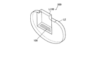
ホログラム光学レンズであるホログラム素子内蔵レンズ200の製造方法は、ホログラム光学基材形成工程と、一体化形成工程とを含む。ホログラム光学基材形成工程であるホログラム光学基材L100の製造方法は、第1光学基材である光学基材L1の一端に傾斜面101を形成し、この傾斜面101にホログラム素子100を形成することにより接眼光学ユニットであるホログラム光学基材L100を形成する。一体化工程は、ホログラム光学基材L100を第2光学基材である光学基材L2と一体化する。ただし、発明の範囲は図示例に限定されない。
Hereinafter, a method for manufacturing a hologram optical substrate and a method for manufacturing a lens with a built-in hologram element will be described with reference to FIGS.
The manufacturing method of the hologram element built-in
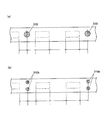
(1)光学基材形成工程
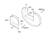
図1に光学基材L1及び光学基材L2の形状の一例を示す。ここで、光学レンズを眼鏡フレームに装着し、ヒトが装着する際の瞳がある方向を背面方向、見える像がある方向を正面方向という。第1光学基材及び第2光学基材の材質は、プラスチック又はガラスである。
(1) Optical base material formation process An example of the shape of the optical base material L1 and the optical base material L2 is shown in FIG. Here, the direction in which an optical lens is attached to a spectacle frame and a pupil when a human wears it is referred to as a back direction, and the direction in which a visible image exists is referred to as a front direction. The material of the first optical substrate and the second optical substrate is plastic or glass.
光学基材形成工程は、射出成形工程、圧縮成形工程、切削り工程、研磨工程などのうちから一つの工程又はこれらの組み合わせ工程から構成されている。光学基材L1の形成は、ホログラム光学基材形成工程の貼付工程前までに形成されていることが好ましい。 The optical base material forming step is constituted by one step or a combination step thereof among an injection molding step, a compression molding step, a cutting step, a polishing step, and the like. The optical base material L1 is preferably formed before the attaching step of the hologram optical base material forming step.
射出成形工程は、原材料を溶解しながら射出ユニットの先端部から加圧した金型の空洞部のキャビティに注入し、冷却して、所定の形状の光学基材を成形する。圧縮成形工程は、ガラス又はプラスッチックの母型にモールドなどを周囲に形成し、圧縮成形し、所定の形状の光学基材に成形する。 In the injection molding process, the raw material is melted and injected from the tip of the injection unit into the cavity of the pressurized mold cavity and cooled to mold an optical substrate having a predetermined shape. In the compression molding process, a mold or the like is formed around a glass or plastic matrix, compression molded, and molded into an optical substrate having a predetermined shape.
切削り工程は、射出成形工程によって形成した光学基材を、ボールエンドミル、回転式カッター、レーザ光線、ウォータジェットなどによって所定の形状の光学基材に形成する。また、研磨工程は、射出成形工程によって形成した光学基材を、CMP(Chemical Mechanical Planarization)などによって研磨し、所定の形状の光学基材に形成する。 In the cutting process, the optical substrate formed by the injection molding process is formed on an optical substrate having a predetermined shape by a ball end mill, a rotary cutter, a laser beam, a water jet, or the like. In the polishing step, the optical substrate formed by the injection molding step is polished by CMP (Chemical Mechanical Planarization) or the like to form an optical substrate having a predetermined shape.
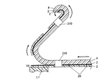
第1光学基材の外形形状の一端には、ホログラム感材の島状部19が貼り付けられる傾斜面101が形成されている光学基材L1が好ましい。下記に説明するように、この傾斜面101に貼り付けられたホログラム感材の島状部19は、レーザ露光などの露光工程、現像工程などによってホログラム素子100に形成されるためである。
The optical base material L1 in which the
これによって、光学基材L1は、ホログラム光学基材L100に形成される。このとき、この傾斜面101は、ホログラム素子内蔵レンズ200がWDやHMDなどとして装着された際に、ヒトの瞳にホログラム映像を導くことができる傾斜角度であるように形成されていることが好ましい。
Thereby, the optical base material L1 is formed on the hologram optical base material L100. At this time, the
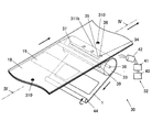
また、図1に示すように凹欠部を有する第2光学基材である光学基材L2を形成する際は、光学基材L1の外形形状に対応して凹欠部を形成する凹欠部形成工程が含まれることが好ましい。ピックアンドプレースなどによって第1光学基材と第2光学基材とを一体化する際に、光学基材L1の外形形状と光学基材L2の凹欠部とが嵌合しやすく、また正面方向からみて略円形状のホログラム素子内蔵レンズを形成し、ユーザのニーズに対応した形状のホログラム素子内蔵レンズ200を切削りによって形成することができるためである。また、光学基材L2の形成は、一体化工程の接着工程前までに形成されていることが好ましい。
Moreover, when forming the optical base material L2 which is a 2nd optical base material which has a recessed part as shown in FIG. 1, the recessed part which forms a recessed part corresponding to the external shape of the optical base material L1 Preferably a forming step is included. When integrating the first optical base material and the second optical base material by pick and place or the like, the outer shape of the optical base material L1 and the recessed portion of the optical base material L2 are easily fitted, and the front direction This is because it is possible to form a lens with a built-in hologram element having a substantially circular shape, and to cut the
図1に示す凹欠部形成工程によって形成される第1光学基材である光学基材L1及び第2光学基材である光学基材L2について説明する。
光学基材L1の外部形状の下方向及び両側面方向の面には、光学基材L2の凹欠部に嵌合する際に接合する接合面102が形成されている。この外部形状の接合面102は、下方向の接合面102aと、正面方向の右側面方向の接合面102bと、正面方向の左側面方向の接合面102cとからなる。接合面102aには、傾斜面101が形成されている。
The optical base material L1 that is the first optical base material and the optical base material L2 that is the second optical base material that are formed by the recess forming step shown in FIG. 1 will be described.
On the surface of the optical base material L1 in the downward direction and the both side surface directions, a joint surface 102 is formed that is joined when the optical base material L1 is fitted into the recessed portion of the optical base material L2. This externally shaped joining surface 102 is composed of a joining
光学基材L2の中央部には、光学基材L1の外形形状の接合面102に対応する凹欠部が形成されている。この凹欠部には、接合面102a、接合面102b及び接合面102cがそれぞれ接合できるように対応する接合面105a、105b及び105cからなる。
A concave portion corresponding to the outer shape joining surface 102 of the optical base material L1 is formed at the center of the optical base material L2. The concave portion includes corresponding
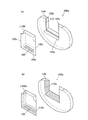
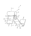
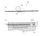
なお、図2a及び図2bに第1光学基材及び第2光学基材の接合面102,105の形状の例示を示す。光学基材形成工程で接合面102,105に、凹部110、微小凹部、梨粒状110eを形成してもよい。また、凹部110は、光学基材の接合面にいずれか一方若しくは両面に外部に連通するように形成してもよい。
2A and 2B show examples of the shapes of the joining surfaces 102 and 105 of the first optical base material and the second optical base material. You may form the recessed
凹部110を形成する個数は特に限定されない。また、凹部の形状は特に限定されないが、多角及び/又は半円形状であることが好ましい。このことによって、光学基材同士の接着力を強化することができる。また、接合面102,105の全面に均一に接着剤が浸透することができる。また、レンズ表面にはみ出す接着剤を少なくすることができる。
The number of
(2)ホログラム光学基材形成工程
以下、図1から図27を参照しながら、ホログラム光学基材の製造方法であるホログラム光学基材形成工程について説明する。
ホログラム光学基材形成工程は、(a)積層シート形成工程、(b)穿孔工程、(c)切断工程、(d)第1剥離工程、(e)貼付工程、(f)第2剥離工程、(g)露光工程及び(h)現像工程からなる。このとき、ホログラム素子形成工程も同様の工程を経て、光学基材L1の傾斜面101に貼り付けたホログラム感材の島状部19をホログラム素子100に形成する。
これら積層シート5などを移送する移送機構は、ローラ群、ピンチローラ群、これらの駆動源であるモータなどを備えており、各工程に設けられている(図示せず)。
(2) Hologram Optical Substrate Formation Step Hereinafter, the hologram optical substrate formation step, which is a method for manufacturing a hologram optical substrate, will be described with reference to FIGS.
The hologram optical substrate forming step includes (a) a laminated sheet forming step, (b) a punching step, (c) a cutting step, (d) a first peeling step, (e) a pasting step, (f) a second peeling step, (G) An exposure step and (h) a development step. At this time, the hologram element forming process goes through the same process to form the island-shaped
The transfer mechanism for transferring the
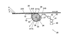
(a)積層シート形成工程は、一対の保護シートの間にホログラム感材シート2が互いに剥離可能に接着されて断面サンドイッチ状に形成された積層シート5を形成する。
(b)穿孔工程は、保護シートであるカバーシート1、ベースシート4の何れか一方の外側面から積層シート5の厚さ方向にパイロット穴310を長手方向及び/又は幅方向に一定間隔で穿孔する。なお、穿孔工程は、(c)切断工程と(d)第1剥離工程との間、(d)第1剥離工程と(e)貼付工程との間にすることも可能である。
(A) In the laminated sheet forming step, the hologram
(B) In the perforating step,
(c)切断工程は、積層シート5の長手方向及び/又は幅方向に形成したパイロット穴310の位置を認識し、認識したパイロット穴310の位置を基準に保護シートのいずれか一方の外面側から積層シート5の厚さ方向に少なくともホログラム感材シート2を切断する深さまで切込みを入れ、ホログラム感材シート2に島状部19を形成するように半切断を行う。
(d)第1剥離工程は、一方の保護シートをホログラム感材シート2から剥離する。
(C) In the cutting step, the position of the
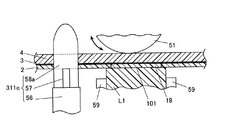
(D) In the first peeling step, one protective sheet is peeled from the hologram
(e)貼付工程は、パイロット穴310の位置を認識し、パイロット穴310の位置を基準に第1光学基材である光学基材L1を配置した治具60を移送し、他方の保護シートであるベースシート4に付着させた状態のホログラム感材の島状部19をホログラム感材の島状部19の位置に対応する第1光学基材である光学基材L1の傾斜面101における所定の位置に位置決めをし、ホログラム感材の島状部19を他方の保護シートに付着させた状態で第1光学基材である光学基材L1の傾斜面101に貼り付ける。又は/及びパイロット穴310の位置の認識をし、パイロット穴310に対応するパイロットピン311cをパイロット穴310に挿入して他方の保護シートであるベースシート4を固定し、固定した他方の保護シートであるベースシート4の外面側から貼付ローラ51によって押圧してホログラム感材の島状部19を第1光学基材である光学基材L1の傾斜面101に貼付ける。
(E) The attaching step recognizes the position of the
(f)第2剥離工程は、積層シート5の長手方向及び/又は幅方向に形成したパイロット穴310の位置を認識し、認識したパイロット穴310の位置を基準にホログラム感材の島状部19のみを第1光学基材である光学基材L1の傾斜面101に残存させた状態で、他方の保護シートと共にホログラム感材の梯子状部18を剥離する。
(g)露光工程は、第2剥離工程の後、第1光学基材である光学基材L1の傾斜面101に貼り付けられたホログラム感材の島状部19にレーザ光を露光する。
(h)現像工程は、露光された島状部19を現像する。
(F) In the second peeling step, the position of the
(G) An exposure process exposes a laser beam to the island-shaped
(H) In the developing step, the exposed
(a)積層シート形成工程
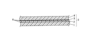
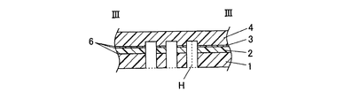
図3は、本発明に用いられる積層シート5の断面図である。
本発明に用いられる積層シート5は、一対の保護シート間にホログラム感材シート2が互いに剥離可能に接着されて断面サンドイッチ状に形成された積層シートに形成されている。なお、予め目的に応じた積層シートがある場合には、積層シート形成工程をスキップしてもよい。
(A) Laminated sheet formation process FIG. 3: is sectional drawing of the
The
積層シート5は、4層構造であって、下から順に第1保護シートであるカバーシート1、ホログラム感材シート2、第3保護シートであるバリアシート3及び第2保護シートであるベースシート4からなる。これらシート間には、シート間を密着させるとともに剥離することができる粘着剤6が塗布されている。この積層シート5の両幅の端部分には、ホログラム感材シート2が接合されていないことが好ましい。両端部分にホログラム感材シート2が接合されていないことによって、カバーシート1、バリアシート3及びベースシート4に突出部分を設けることができ、その突出部分からシートの剥離が行いやすいためである。
The
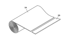
図4に、積層シート5の一例であるこの母材をロール状に巻いたジャンボロール体5Aを示す。さらに積層シート5の他の一例として、ジャンボロール体をその軸方向に所定のピッチ幅において径方向に裁断することによりロール状に巻かれているパンケーキ状に形成する、又はジャンボロール状積層シート又はパンケーキ状積層シートを長手方向又は側面方向から平行に裁断することにより帯状に形成する積層シート5B(以下、帯状積層シート5Bとする。)が挙げられる。積層シート5は、パンケーキ状、短冊状、多角形状、円形状などに断裁されたもの、裁断後パンケーキ状に巻き取られたものなど、何れの形状に形成してもよい。
FIG. 4 shows a
積層シート5の素材について説明する。
カバーシート1、バリアシート3及びベースシート4の素材としては、例えば、紙、プラスチック、ガラス、金属などが挙げられる。状況に応じてロール状や平坦状にすることができる可撓性があり、内部のホログラム感材に傷を与えにくい強度をもつ、紙又はプラスチックがよい。
The material of the
Examples of the material of the
金属としては、例えば、アルミ、ステンレスなどが挙げられる。プラスチックとしては、例えば、ポリエステル、ポリスチレン、ポリカーボネイト、ポリエーテルスルホン、ポリイミド、ポリシクロペンタジエン、ポリノルボルネン、ナイロン、セルロースアセテートなどが挙げられる。ポリエステルとしては、例えば、ポリエチレンテレフタレート、ポリエチレンナフタレートなどが挙げられる。 Examples of the metal include aluminum and stainless steel. Examples of the plastic include polyester, polystyrene, polycarbonate, polyethersulfone, polyimide, polycyclopentadiene, polynorbornene, nylon, and cellulose acetate. Examples of the polyester include polyethylene terephthalate and polyethylene naphthalate.
カバーシート1、バリアシート3及びベースシート4の素材としては、ポリエチレンナフタレート及びシンジオタクチック構造を有するスチレン系重合体を含むプラスチックが挙げられる。適度な可撓性及び強度をもつポリエチレンテレフタレートが最も好ましい。
Examples of the material for the
ホログラム感材シート2は、ホログラム感光性組成物、色素組成物、発熱吸熱組成物などの化学組成物などとバインダーとを含んだものをシート状に形成したものである。ホログラム感光性組成物は、感光性ハロゲン化銀、非感光性有機銀塩、光重合剤及び還元剤などを含むものからなる。ホログラム感材シート2には、ホログラム感光性組成物及びバインダーなどを含むホログラム感材シートがある。このホログラム感材シートは、レーザ光、紫外線照射、ベイク処理などによってホログラムの映像を形成するホログラム素子になる。
The hologram
このバインダーとして、天然ポリマー、合成ポリマー及びコポリマー、その他シートを形成する媒体などが挙げられる。例えば、ゼラチン、アラビアゴム、ポリビニルアルコール、ヒドロキシエチルセルロース、セルロースアセテート、セルロースアセテートブチレート、ポリビニルピロリドン、カゼイン、デンプン、ポリアクリル酸、ポリメチルメタクリレート、ポリメタクリ酸、ポリ塩化ビニル、コポリ(スチレン−無水マレイン酸)、コポリ(スチレン−アクリロニトリル)、コポリ(スチレン−ブタジエン)、ポリビニルアセタール類、ポリビニルホルマール、ポリビニルブチラール、ポリエステル類、ポリウレタン類、フェノイキシ樹脂、ポリ塩化ビニリデン、ポリエポキシド類、ポリカーボネ−ト類、ポリビニルアセテート類、セルロースエステル類、ポリアミドなどがあり、親水性でも非親水性でもよい。これらは、溶解する溶媒と共に溶液として用いてもよいし、ラテックスのような水分散物の形状で用いてもよい。 Examples of the binder include natural polymers, synthetic polymers and copolymers, and other media for forming sheets. For example, gelatin, gum arabic, polyvinyl alcohol, hydroxyethyl cellulose, cellulose acetate, cellulose acetate butyrate, polyvinyl pyrrolidone, casein, starch, polyacrylic acid, polymethyl methacrylate, polymethacrylic acid, polyvinyl chloride, copoly (styrene-maleic anhydride) ), Copoly (styrene-acrylonitrile), copoly (styrene-butadiene), polyvinyl acetals, polyvinyl formal, polyvinyl butyral, polyesters, polyurethanes, phenoxy resins, polyvinylidene chloride, polyepoxides, polycarbonates, polyvinyl acetates , Cellulose esters, polyamides and the like, which may be hydrophilic or non-hydrophilic. These may be used as a solution together with a solvent to be dissolved, or may be used in the form of an aqueous dispersion such as latex.
積層シート5の外側を保護する保護シートであるカバーシート1及びベースシート4の厚さ寸法は、ホログラム感材シート2を保護するための強度と可撓性を確保するため、20μmから200μmが好ましい。ホログラム感材シート2を直接を保護する保護シートであるバリアシート3の厚さ寸法は、ホログラム感材シート2に直接接合して保護するための強度と可撓性とを確保するため、2μmから20μmが好ましい。ホログラム感材シート2の厚さは、10μmから30μmが好ましい。
The thickness dimensions of the
各シート間に塗布する粘着剤6は、各シートが接合して密着できるとともに剥離することができれば、特に限定されるものではない。例えば、アクリル系樹脂、アクリル酸エステル樹脂、またはこれらの共重合体、ゴム系樹脂、シリコーン系樹脂、酢酸ビニル系樹脂、ウレタン系樹脂、アクリロニトリル、炭化水素樹脂、フェノール系樹脂、アルキルフェノール樹脂、ロジン系樹脂、テルペン樹脂、クロマンインデン樹脂、ポリビニルエーテル、マレイミド系、ポリオレフィン系、ポリビニルエーテル系などのいずれか一つ又はこれらの複合物が挙げられる。また、イソシアネート系架橋剤、金属キレート系架橋剤等を添加して架橋する、いわゆる二液架橋型粘着剤でもよい。
The pressure-
ゴム系樹脂は、例えば、ブチルゴム、ポリイソプレン、ポリイソブチレン、ポリクロロプレン、ニトリルブタジエンゴム、アクリルゴム、スチレン−ブタジエン共重合樹脂、などが挙げられる。酢酸ビニル系樹脂は、例えば、ポリ酢酸ビニル、エチレン酢酸ビニル共重合体などが挙げられる。ロジン系樹脂は、例えば、ロジン、ロジンエステル、ロジントリグリセリド、水素化ロジンなどが挙げられる。 Examples of the rubber-based resin include butyl rubber, polyisoprene, polyisobutylene, polychloroprene, nitrile butadiene rubber, acrylic rubber, and styrene-butadiene copolymer resin. Examples of the vinyl acetate resin include polyvinyl acetate and ethylene vinyl acetate copolymer. Examples of the rosin resin include rosin, rosin ester, rosin triglyceride, hydrogenated rosin and the like.
この粘着剤6の粘着力は、一方の保護シートとホログラム感材シートとの接着強度が、他方の保護シートとホログラム感材シートとの接着強度より相対的に高い方が好ましい。粘着力は、密着と剥離との両方を満たすように、ピール試験で10g/25mmから100g/25mmまでが好ましい。さらに、カバーシート1、ベースシート4、バリアシート3の順に剥離が行いやすいように、バリアシート3/ホログラム感材シート2間、ホログラム感材シート2/カバーシート1間、ベースシート4/バリアシート3間の順に密着力が強い方が好ましい。又、接着剤を塗布する厚さ寸法は、1μmから50μmであればよい。1μmから20μmの厚さ寸法が好ましい。粘着剤6の厚さ寸法は、30μm以下が好ましい。積層シートの全体の厚さ寸法を抑えることができるからからである。
The adhesive strength of the pressure-
(b)穿孔機構
図5及び図6に、穿孔機構300の概略図を示す。
図5に示すように、穿孔機構300には、積層シート5にパイロット穴310を穿孔する突起部301、突起部301を摺動させる摺動機構(図示せず)、この突起部301などを設ける固定台304、積層シート5を固定台304とともに固定する固定板302などが備えられている。
(B) Drilling mechanism FIGS. 5 and 6 are schematic views of the
As shown in FIG. 5, the
この突起部301の下部には、突起部301を支持するための支持体303が設けられている。この支持体303の下部には、摺動機構が設けられている。この摺動機構によって支持体303が摺動するとともに、この支持体303の上部に設けられている突起部301が摺動する。摺動した突起部301は、積層シート5を穿孔してパイロット穴310を形成する。
A
固定台304には、支持体303が摺動するための内部孔305,305が設けられている。この内部孔305の内部形状は、支持体303の形状に対応し、支持体303が摺動することができる形状である。また、内部孔305の積層シート5に接する端部には、内部孔305の内部方向に突起したストッパー306,306が設けられている。ストッパー306,306によって支持体303が内部孔305から飛び出すことを防止しつつ、突起部301が積層シート5を穿孔してパイロット穴310を形成する。
The fixing
固定板302には、パンチ孔302a,302aが設けられている。このパンチ孔302aは、突起部301が積層シート5を穿孔し、積層シート5にパイロット穴310とともに積層シート片309を形成する際に、突起部301が摺動でき、積層シート片309を回収できるように形成されている。
これによって、保護シートであるカバーシート1又はベースシート4の何れか一方の外側面から積層シート5の厚さ方向にパイロット穴を長手方向及び/又は幅方向に一定間隔で穿孔することができる。
The fixing
Thereby, pilot holes can be drilled at regular intervals in the longitudinal direction and / or the width direction from the outer surface of either the
さらに、固定板302及び固定台304の外部には、ラック機構、電動モータなどが設けられている。このラック機構などは、固定板302及び固定台304が積層シート5を挟むように開閉運動する。開閉運動によって、穿孔前の積層シート5を固定板302及び固定台304を閉じて固定する又は固定板302及び固定台304を開いて穿孔後の積層シート5を次の工程に移送することができる。
Further, a rack mechanism, an electric motor, and the like are provided outside the fixed
摺動機構は、突起部301が積層シート5にパイロット穴310を穿孔することができれば、機構は特に限定されない。
例えば、油空圧機構、カム・リンク機構、電磁力機構などが挙げられる。
油空圧機構の場合には、例えば、圧縮空気の射出による又は往復運動による突起部301の摺動が挙げられる。圧縮空気の射出の場合には、支持体303の下部には、圧縮空気の通路(図示せず)が設けられている。この通路の末端には、圧縮空気を射出する圧縮空気射出機(図示せず)が設けられている。この圧縮空気が射出することによって突起部301を上方向に摺動させる。
The sliding mechanism is not particularly limited as long as the
Examples thereof include an oil / pneumatic mechanism, a cam / link mechanism, and an electromagnetic force mechanism.
In the case of the hydraulic / pneumatic mechanism, for example, sliding of the
往復運動の場合には、支持体303をピストンとし、内部孔305をシリンダとする。この支持体303の下部には、ピストンロッド(図示せず)が設けられている。このピストンロッドは駆動部(図示せず)に接続されており、ピストンロッドを動かすことによって、突起部301を摺動させる。
In the case of reciprocating motion, the
カム機構の場合には、例えば、変形カム(図示せず)及びカム棒(図示せず)による突起部301の摺動が挙げられる。この場合には、支持体303の下部には、カム棒の一方の一端が連結されている。このカム棒の他方の一端には、変形カムがカム棒に接するように設けられている。この変形カムの回転によってカム棒が上下運動することによって支持体303の上部にある突起部301が上下に摺動する。
In the case of a cam mechanism, for example, sliding of the
また、リンク機構の場合には、例えば、テコやクランクによる突起部301の摺動が挙げられる。支持体303の下部にクランク棒(図示せず)が連結されており、このクランク棒が駆動部(図示せず)からの駆動をテコやクランクの運動によって上下運動する。このことによって突起部301を摺動させる。
In the case of a link mechanism, for example, sliding of the
電磁力機構の場合には、例えば、支持体303を磁性体とし、電磁コイルとの反発による突起部301の摺動が挙げられる。固定台304の内部孔305の周囲に電磁コイル(図示せず)を設け、電磁コイルに電流を通電することによって電磁力を発生させることによって突起部301を摺動させることなどが挙げられる。
In the case of an electromagnetic force mechanism, for example, the
積層シート5における長手方向及び/又は幅方向に形成されるパイロット穴310の個数、配置、形状は特に限定されない。また、積層シート5に形成されるパイロット穴310に対応するように突起部301の個数、配置、形状が形成されている。さらに、この突起部301の個数、配置、形状に対応するように固定板302、パンチ孔302a、支持体303、内部孔305などを変更する。
The number, arrangement, and shape of the
図6aは、突起部301によって穿孔され、形成されるパイロット穴310の形状の一例である。パイロット穴310の形状は、円形状、三角形状、四角形状、多角形状など特に限定されない。多角形状などのパイロット穴310を積層シート5に形成する場合には、穿孔機構300においてパイロット穴310の形状に対応する突起部301に変更する。
FIG. 6 a is an example of the shape of the
また、パイロット穴310を積層シート5の長手方向に一定間隔で穿孔する際、各パイロット穴310からいずれか一方に隣接するパイロット穴310までに単数又は複数の島状部19を形成する。
例えば、パイロット穴310同士の間に2つの島状部19を1セットとして繰り返し形成する。パイロット穴310は1セット間の略中間ごとに形成する。パイロット穴310からいずれか一方に隣接するパイロット穴310までの間に2つの島状部を1セットすることが好ましい。
In addition, when the
For example, two
このことによって、2基の光学基材L1に同時にホログラム感材の島状部19を貼付けることができる。また、貼付工程で、2つのホログラム感材の島状部の両端がパイロットピンなどで位置決めし、固定することができる。このため、ホログラム感材のノビが少なくしてホログラム感材の島状部19の貼付けを正確に行うことができる。
By this, the island-shaped
積層シート5の幅方向におけるパイロット穴の個数は単数又は複数のいずれでもよく、特に限定されない。図6bに示すように、パイロット穴310b,310bは、積層シート5の幅方向に2つ並列して形成されることが好ましい。貼付工程において光学基材L1の傾斜面で幅方向が狭いため、ホログラム感材の島状部19を貼り付ける際の幅方向の位置決め及び固定を正確にすることができる。
The number of pilot holes in the width direction of the
さらに、積層シート5にパイロット穴310b,310bを形成し、貼付工程を行った場合には、貼り付けた後のホログラム感材の島状部19の中に気泡が生じにくく、ズレ、シワ、タワミが低減することができる。さらに、太鼓形状の貼付ローラを用いることが好ましい。ホログラム感材の島状部19を押圧する際にホログラム感材の島状部19は幅方向に弓形状になりながら中央付近から光学基材L1の傾斜面101により密着しながら貼付けを行うことができる。
Further, when pilot holes 310b and 310b are formed in the
(c)切断機構
図7から図12に、切断機構9、切断機構9bの概略図を示す。
図7及び図8に示すように、切断機構9には、積層シート5に島状部19の切込みを入れる切込みローラ群10、これらの駆動源であるモータなどが備えている。切込みローラ群10には、切込みローラ11と支持ローラ12とが備えられている。この切込みローラ11と支持ローラ12との間には、積層シート5に切込みを入れて島状部19を形成するための隙間が設けられている。
(C) Cutting mechanism FIGS. 7 to 12 are schematic views of the
As shown in FIGS. 7 and 8, the
この切込みローラ11の両側には、支持ローラ12の回転によって切込みローラ11を回転させる円柱形状の2つの鍔部13が支持ローラ12に接するように設けられている。これら鍔部13の側面の中央付近には、鍔部13の直径を変更することができる調整部14が設けられている。この調整部14でこの鍔部13の直径を変更することによって切込みローラ11と支持ローラ12との隙間を調整する。
On both sides of the cutting
この切込みローラ11の表面中央付近には、上下移動可能な切込み刃台(図示せず)が設けられている。この切込み刃台は、切込みローラ11の表面に対応して湾曲しており、切込み刃15が上部に備えられている。この切込み刃15は、ローラ表面に対応して湾曲しおり、切込み刃台から脱着可能である。この切込み刃15によって積層シート5に厚さ方向から切込みが入れられ、島状部19が形成される。
In the vicinity of the center of the surface of the cutting
さらに、この切込み刃台は、調整部14によって上下移動距離の調整をすることができる。切込み刃台の上下移動距離の調整をすることによって積層シート5に形成される島状部の切込みの深さを調整し、切込み刃15の輪郭線に沿って積層シート5を切断状態、半切断状態、非切断状態として半切断部20又は非切断部21を形成することができる。
Furthermore, this cutting blade base can adjust the vertical movement distance by the adjusting
さらに、切込み刃15付近には、積層シート5に形成されたパイロット穴310に対応し、嵌合するパイロットピン311a及び/又は位置センサーが設けられていることが好ましい。
また、積層シート5の長手方向であってパイロット穴310からいずれか一方に隣接するパイロット穴310までの間にホログラム感材の島状部19を形成する場合には、切込みローラ11の表面に設けられているパイロットピン311aからいずれか一方に隣接するパイロットピン311aまでの間に単数又は複数の切込み刃15が設けられている。形成するホログラム感材の島状部19の個数に対応するように単数又は複数の切込み刃が設けられている。
Furthermore, it is preferable that a
Further, when the island-shaped
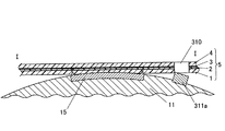
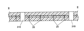
図9aから図9cに、形成された島状部19と梯子状部18との輪郭線及びパイロット穴310の一例を示し、特に例示には限定されない。また、図10及び図11に図9bの断面図を示す。
半切断部20は、保護シートであるカバーシート1又はベースシート4のいずれか一方の外面側から積層シート5の厚さ方向に少なくともホログラム感材シート2を切断する深さで、且つ、ホログラム感材の島状部19の輪郭線に沿って切り込まれて形成される。
FIG. 9a to FIG. 9c show an example of the contour line of the formed island-shaped
The half-
この半切断部20の輪郭線は、多角形状、楕円形状など特に限定されないが、光学基材L1の傾斜面101に対応する形状が好ましい。ホログラム素子100がズレのない映像を形成することができるからである。光学基材L1の傾斜面101が四角形状である場合には、切込み形状は略四角形状であることが好ましい。
The outline of the half-
ここで、厚さ寸法とは、積層シート5の外面側から積層シート5の厚さ方向にいずれか一方の保護シートから切込み刃15で切込みを入れた刃の先端までの距離Hをいう。切込み刃15の先端がカバーシート1又はベースシート4のいずれか一方の外面側から積層シート5の厚さ方向に少なくともホログラム感材シート2を切断する深さまで切断した部分を半切断部20といい、カバーシート1を全く切断していない又は一部に達する深さまで切った部分を非切断部21という。
Here, the thickness dimension refers to the distance H from the outer surface side of the
図9aに示すように、半切断部20はホログラム感材の島状部19の輪郭線に沿って連続するように切断して形成することが好ましい。
図9b、図9c、図10及び図11に示すように、切込み刃15によって積層シート5をホログラム感材の島状部19の輪郭線に沿って半切断部20と非切断部21とを交互に形成する。半切断部20と非切断部21とを等間隔に形成、つまり、半切断部20は、ホログラム感材の島状部19の輪郭線に沿って断続的にミシン目状に切断して形成することが好ましい。
As shown in FIG. 9a, the half-
As shown in FIGS. 9b, 9c, 10 and 11, the cutting
半切断部20は、ホログラム感材の島状部19の輪郭線に沿って断続的にミシン目形状に形成することによって、カバーシート1の剥離の際にカバーシート1の島状部19が梯子状部18と一緒に巻取りローラで回収することができる。さらにバリアシート3付きホログラム感材の島状部19を光学基材L1に貼付け、ホログラム感材の梯子状部18のみを剥離することができる。
The
さらに、非切断部21の輪郭線の全長さ寸法は、半切断部20の輪郭線の全長さ寸法より短い方が好ましい。ホログラム感材シート2貼付け工程により光学基材L1にホログラム感材シート2を貼付けた後、第2剥離工程でホログラム感材の梯子状部18がベースシート4とともに容易に剥離することができるためである。一方の保護シートをホログラム感材シートから剥離する際に、一方の保護シートをすべて剥離しつつ、一方の保護シート側に光学基材L1に貼付け可能な状態のホログラム感材の島状部19を残存させることができる。
このとき、非切断部21と半切断部20の全長寸法の比率は、半切断部20の全長さ寸法を1としたときに、1×10⁻¹から1×10⁻⁶であることが好ましい。さらに、非切断部21の比率は、1×10⁻³から1×10⁻⁵であることが好ましい。
Furthermore, it is preferable that the total length of the contour line of the
At this time, the ratio of the full length dimension of the
また、半切断部20における積層シート5の長手方向にあるいずれか一方の辺に非切断部21を設けるように形成することが好ましい。一方の保護シートであるカバーシート1又はベースシート4を非切断部21側から長手方向に沿って剥離することによって、一方の保護シートの剥離に際して、半切断部20で囲まれるカバーシート1の島状部19と梯子状部18とが非切断部21でつながって剥離することができる。このため、従来のようにカバーシート1を島状部19と梯子状部18とに分けて2回剥離する必要がなく同時に剥離することができる。さらに、一方の保護シートの剥離方向上流側の位置に、非切断部を設けるように形成することが好ましい。
Moreover, it is preferable to form so that the non-cut | disconnecting
また、ホログラム感材の島状部19を光学基材L1に貼り付けた後、非切断部21側の反対側から長手方向に沿って梯子状部18を剥離することによって、ホログラム感材の島状部19のみを光学基材L1の傾斜面101に残存させた状態で、他方の外面側の保護シートであるベースシート4と共にホログラム感材の梯子状部18及びホログラム感材シート2の内側保護シートであるバリアシート3の梯子状部18とを剥離することができる。また、半切断部20の輪郭線の全長さ寸法が長く形成されているため容易に剥離することができるので、剥離工程中にホログラム感材シート2のシワ、タワミなどが生じにくい。
Further, after the island-shaped
切込み刃15の先端が、積層シート5の厚さ方向から、半切断部20における切込みの深さは、保護シートのカバーシート1又はベースシート4のいずれか一方の外面側から積層シート5の厚さ方向において少なくともホログラム感材シート2を切断し、且つ、他方の保護シートの一部に達する深さであることが好ましい。
一方の保護シートであるカバーシート1、ホログラム感材シート2及びバリアシート3を切断し、他方の保護シートであるベースシート4の一部に達する深さまで切るように調整部14によって調整する。このことによって、ホログラム感材の島状部19にシワやタワミが生じることなく、ホログラム感材の梯子状部18のみを容易に剥離することができる。
The tip of the
The
さらに、切込み刃15の先端を、カバーシート1の厚さ方向から入れ、ベースシート4の10%から80%まで入れることが好ましい。切込み刃15がベースシート4の一部に達する深さまで厚さ方向から切ることによって、光学基材L1にホログラム感材の島状部19を貼付け後、他方の保護シートを剥離する際に、不要となったホログラム感材の梯子状部18を取り除きながらホログラム感材の島状部19のみを光学基材L1の傾斜面101に残存させることができる。このことによって、ホログラム感材の梯子状部18を剥離する工程と、ベースシート4の梯子状部18と島状部19とを剥離する工程とを一つの工程で行うことができる。
Furthermore, it is preferable to insert the tip of the
さらに、切込み刃15の先端を、カバーシート1の厚さ方向から入れ、ベースシート4の20%から80%まで達する深さに切り込むことが好ましい。また、他方のカバーシートを剥離する際に、光学基材L1の傾斜面101に接着しているホログラム感材の島状部19にウキが生じることなく、精度の高いホログラム素子100を形成することができる。ホログラム感材の梯子状部18を剥離する際の剥離ローラ33などの引っ張り力によってベースシート4が島状部19と梯子状部18とに切れて分かれないためである。
Furthermore, it is preferable that the tip of the
さらに、切込み刃15の先端を、カバーシート1の厚さ方向から入れ、ベースシート4の30%から70%まで達する深さに切り込むことが好ましい。形成されたベースシート4の半切断部20が剥離ローラ33の表面に沿って折れ曲がることによってベースシート4に接着しているホログラム感材の梯子状部18がホログラム感材の島状部19から容易に剥離することができるためである。さらに、切込み刃の先端を、カバーシート1の厚さ方向から入れ、ベースシート4の30%から50%の深さまで切り込むことが好ましい。
Furthermore, it is preferable that the tip of the
なお、帯状積層シート5Bを形成し、帯状積層シート5Bの長手方向に島状部19を互いに所定の間隔を置いて一方向に複数形成し、長手方向に複数の島状部19の間にパイロット穴310を形成することが好ましい。連続的に効率よく複数のホログラム感材の島状部19を形成し、さらにホログラム感材の島状部19を光学基材L1の傾斜面に1ユニットごとに貼付け、ホログラム感材の島状部19を貼り付けた光学基材L1を複数形成することができる。
The strip-shaped laminated sheet 5B is formed, and a plurality of
また、パイロット穴310に基づいてホログラム感材の島状部を光学基材L1の傾斜面に貼付けるため、シートの幅方向の位置決めが行いやすく、ブレが少ない。また長手方向の位置決め及び固定を行いやすく、ホログラム感材のノビが少ない。従って、連続的に効率よく複数のホログラム素子100の形成が可能であり、生産性が向上する。ここで、ジャンボロール体5A、パンケーキ状に上記切断機構9により半切断部20を形成後、裁断により帯状積層シート5Bに形成するものも帯状積層シートに含まれる。
In addition, since the island-shaped portion of the hologram sensitive material is attached to the inclined surface of the optical base material L1 based on the
なお、図12に示すように、切込みローラ11に代えて切込み板11bとした切断機構9bでもよい。切込み板11bには、支持ローラ12bの面する側に平坦な切込み刃15bが設けられている。この切込み板11bは、支持ローラ12bの回転を略水平に移動するように設けられている。また切込み板11bの下部には、切込み板11bを移動させるこのローラ群が備えられており、このローラ群は支持ローラ12bなどから駆動が得られるようになっている。
In addition, as shown in FIG. 12, it may replace with the cutting
さらに、切込み刃15b付近には、積層シート5に形成されたパイロット穴310に対応するパイロットピン311a2が設けられていることが好ましい。なお、切込み刃15bが複数ある場合には、パイロットピン311a2は切込み刃15bの両端に設けられていることが好ましい。
Furthermore, it is preferable that a pilot pin 311a2 corresponding to the
また、ローラの回転による切込み以外に、プレス方式によって上方及び/又は下方から積層シート5に切込み刃を用いて切込みを入れてもよい。
このとき、切込み刃15の切込み形状は、上記切込み刃15によって形成される切込み形状と同様である。また半切断部20及び非切断部21の形状も上記と同様である。
Further, in addition to the cutting by the rotation of the roller, the
At this time, the cutting shape of the
また、パイロット穴310の位置の認識に、パイロットピン311a,311a2の他に、位置センサーなどを用いてもよい。積層シート5に形成されているパイロット穴310の位置を位置センサーによって認識し、パイロット穴310とパイロットピン311a又はパイロットピン311a2とを嵌合させることが好ましい。パイロット穴310とパイロットピン311a又はパイロットピン311a2とが対応し、嵌合することによって、単数又は複数のホログラム感材の島状部19を積層シート5の所定の位置に正確に切込み形成することができる。
In addition to the
パイロット穴310を積層シート5に形成し、パイロット穴310を認識するパイロットピン311a,311a2及び/又は位置センサーを切断機構9,9bに設けることによって、パイロットピン311a,311a2及び/又は位置センサーがパイロット穴310を認識し、認識したパイロット穴310の位置を基準に半切断部20を形成することができる。より正確な位置にホログラム感材の島状部19が形成できるため、貼付工程において光学基材L2における傾斜面の所定の位置にホログラム感材の島状部19の正確な貼付けが容易となる。
By forming
(d)第1剥離機構
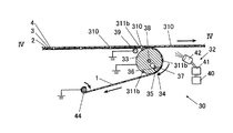
図13から図16に第1剥離機構30の概略を示す。
第1剥離機構30は、除電手段を設けた剥離機構であり、剥離ローラ33、導電性部材39と、除電流体噴付け機32と、剥離したカバーシート1をホログラム感材シート2から引き剥がす巻取りローラ44となどから構成されている。剥離ローラ33、導電性部材39及び巻取りローラ44は接地されており、除電手段として機能する。
(D) 1st peeling mechanism The outline of the
The
図13、図14及び図16に示すように、積層シート5から一方の保護シートであるカバーシート1の外面側を吸引して引き離して離間させる方向にカバーシート1を誘導する剥離ローラ33が設けられている。このとき、剥離ローラ33によってホログラム感材シート2から保護シートが引き剥がされる領域を剥離部という。
As shown in FIGS. 13, 14, and 16, a peeling
剥離ローラ33の表面には、保護シートの外面側を吸引してローラ表面に密着させてホログラム感材シート2から引き剥がすための吸引孔34が設けられている。この吸引孔34の外周部には、溝が設けられており、この溝にはパッキンが圧入されている(図示せず)。また、この吸引孔34には、ローラ軸38近傍を末端としてローラ表面まで延びている吸引通路35が接続されている。この吸引通路35の中途部には、積層シート5に対しての吸引力が減少することを防ぐため逆止弁36が設けられている。吸引通路35の末端には、ローラ軸38の近傍にローラ軸38と略平行に設けられている集合吸引通路37が接続されている。この集合吸引通路37の末端には、吸引ポンプ(図示せず)が接続されている。
The surface of the peeling
第1剥離機構30には、さらに、積層シート5より剥離した一方の保護シートであるカバーシート1を引っ張るための装置である巻取りローラ44が配置されている。この巻取りローラ44に導電性部材39が備えられてもよい。巻取りを開始するカバーシート1の端部を両面接着テープによる接着や直接固定などによって巻取りローラ44に固定し、積層シート5から保護シートであるカバーシート1を離間し、巻取りローラ44で巻取りながら除電を行ってもかまわない。
The
また、第1剥離機構30には、カバーシート1を剥離した積層シートの移送方向の末端を引っ張るための装置が備えられていることが好ましい。剥離ローラ33によるカバーシート1の剥離を行いやすくするためである。
Moreover, it is preferable that the
剥離部の近傍における保護シートであるカバーシート1又は/及びベースシート4に接触する部分に、接地する導電性部材39が備えられていてもよい。導電性部材39は、カバーシート1又は/及びベースシート4の接する部分に単数又は複数設けてもよい。
なお、剥離ローラ33の表面には、導電性部材39で覆われていてもよい。また、導電性部材39が少なくとも剥離ローラ33の表面の一部に設けられており、この部分に保護シートが接触するように設けられていればよく、剥離ローラ33自体が導電性部材39であってもよい。
A
The surface of the peeling
導電性部材39の形状として、ローラ形状、棒状、板形状、又はすだれ形状などが挙げられ、積層シート5と接する面が広くなるように形成されていることが好ましい。すだれ形状は、積層シート5と接することにより、上方のピン軸を介して揺動するように備えられていることが好ましい。またローラ形状は、積層シート5と接することにより、中心のローラ軸を介して回転するように備えられていることが好ましい。
Examples of the shape of the
導電性部材39の材質としては、導電性の高い材質が好ましく、金属、導電性繊維、導電性プラスチック、導電性紙などが挙げられる。特に金属は導電性が高いため好ましく、さらにその金属としては、銅、銀、アルミニウム、鉄、金、白金など又はこれらの合金が好ましい。
The material of the
除電手段である除電流体噴付け機32には、除電流体を発生させる除電流体発生器40、発生させた除電流体の風量を調整するファン41及びシートの剥離面に除電流体を噴付けする噴付け口42などが設けられている。正又は負のイオンの除電流体を発生させる除電流体発生器40には、流路を介してこの除電流体を移送するファン41が接続されている。さらに、このファン41には、流路を介して噴付け口42が接続されている。この噴付け口42は、積層シート5の長手方向又は両幅方向に除電流体が噴付けできるように配置されている。
The discharging
噴付け口42から除電流体を剥離するシートとシートとの間又は島状部19と梯子状部18とが接する切断面に噴付けすることによって、静電気放電の発生を低減してホログラム感材シート2の感光などの化学的変化を抑制することができるとともに除電流体の流速を調整することによってシートの剥離を補助し、ホログラム感材に生じるシワ、タワミ、ウキなどを低減することができる。
除電流体発生器40は、コロナ放電タイプ又は軟X線タイプなどが挙げられる。噴付け口42の設置数を増やしたり、噴付け口42の口径を小さくしたりする方が好ましい。このことによって、シート剥離面の除電効果を高めると共に補助的に剥離を助けることができるためである。
Hologram sensitive material sheet reduces the occurrence of electrostatic discharge by spraying between the sheet from which the current removing member is peeled from the
Examples of the current
なお、剥離ローラ33の表面には、カバーシート1とホログラム感材シート2とをより剥離できるように吸引孔34などの吸引する機構が設けられていることが好ましいが、吸引する機構が設けられていなくともかまわない。
また、図15に示すように、巻取りローラ44を設けず、積層シート5から保護シートであるカバーシート1を離間し、巻き取るように剥離ローラ33が除電手段として機能してもよい。この場合、巻取りを開始する保護シートであるカバーシート1の端部を接着や直接固定などによって剥離ローラ33に固定する。除電手段として、剥離ローラ33、導電性部材39、除電流体噴付け機32が設けられている。
In addition, it is preferable that a suction mechanism such as a
Further, as illustrated in FIG. 15, the take-up
なお、剥離ローラ33の表面には、積層シート5に形成されたパイロット穴310に対応し、嵌合するパイロットピン311bが設けられていることが好ましい。パイロットピン311bの形状、個数、配置は、積層シート5に形成されたパイロット穴310の形状、個数、配置に対応するように剥離ローラ33の表面に形成されている。
また、パイロット穴310の位置の認識に、パイロットピン311bの他に、位置センサーなどを用いてもよい。積層シート5に形成されているパイロット穴310の位置を位置センサーによって認識し、パイロット穴310とパイロットピン311bとを対応させ、嵌合させることが好ましい。
In addition, it is preferable that the surface of the peeling
In addition to the
パイロット穴310の位置を認識し、パイロット穴310とパイロットピン311bとが対応し、嵌合することによって、一方の保護シートであるカバーシート1が剥離ローラ33表面上ですべることなく、カバーシート1を剥離することができるのでホログラム感材シート2のノビを低減することができる。
By recognizing the position of the
この場合、保護シートの外面を吸引するための吸引孔34などを設けなくともよい。パイロット穴310とパイロットピン311bとが嵌合することによって、保護シートを密着することができるためである。また、パイロットピン311bを接地するようにして導電性部材39としてもよい。
In this case, the suction holes 34 for sucking the outer surface of the protective sheet need not be provided. This is because the protective sheet can be brought into close contact by fitting the
(e)貼付機構
図17から図22に貼付機構50の概略を示す。
貼付機構50には、位置決め固定機構501と、ローラ貼付機構502と、積層シートを移送する移送機構(図示せず)、これらを制御する制御機構(図示せず)などが備えられている。
(E) Pasting mechanism FIGS. 17 to 22 show an outline of the
The
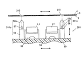
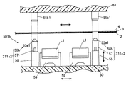
図17及び図18に示すように、位置決め固定機構501は、2基のパイロットピン311cと、2基の光学基材支持台59と、パイロットピン311c,311c及び光学基材支持台59,59を上部に設ける治具60と、治具60を移送する駆動モータ(図示せず)となどから構成されている。
位置決め固定機構501は、パイロット穴310の位置を認識し、パイロット穴310の位置を基準に光学基材L1及びパイロットピン311cを配置した治具60が移送される。移送された治具60に配置されたパイロットピン311c,311cをパイロット穴310,310に挿入して、ホログラム感材の島状部の位置に対応する光学基材L1の傾斜面101における所定の位置に位置決めをする。及び/又はベースシート4を長手方向及び/又は幅方向に固定する。
As shown in FIGS. 17 and 18, the positioning and
The positioning and
移送機構及び治具60に設けられている駆動モータは、積層シート5のパイロット穴310の下方にパイロットピン311cが配置されるように積層シート5と治具60とを長手方向及び/又は幅方向に移送する。また、治具60は、パイロットピン311cがパイロット穴310に挿入及び離脱するように上下に移動する。
The drive motor provided in the transfer mechanism and the
治具60の上部であって長手方向の両端には、2基の光学基材支持台59を挟むように2基のパイロットピン311cが設けられている。また、光学基材支持台59,59の配置間隔は、上記切断機構9で形成したホログラム感材の島状部19,19の間隔と同様である。さらに、パイロットピン311c,311cの配置間隔は、上記穿孔機構300で形成したパイロット穴310からいずれか一方に隣接するパイロット穴310までの間隔と同様である。
Two
パイロットピン311cは、パイロットピン支持体56と、シート支持体57と、先端部58aとなどから構成されている。
治具60の上部には、パイロットピン支持体56が設けられている。このパイロットピン支持体56の上部には、2基のシート支持体57と1基の先端部58aとが設けられている。この先端部58aの両側に、2基のシート支持体57が設けられている。
図18に示すように、パイロットピン311cにパイロット穴310を挿入した際に、シート支持体57,57はホログラム感材シート2に接合し、シートを維持する高さになるように先端部58aより低く配置されている。
The
A
As shown in FIG. 18, when the
パイロットピン311cは、治具60の上に配置し、パイロットピン311cの配置はパイロット穴310の位置に対応した配置であればよい。また、パイロットピン311cの個数はパイロット穴310の個数に対応し、単数又は複数でもよい。
つまり、パイロット穴310の位置に対応する、単数又は複数のパイロットピン311cを治具60に配置し、パイロットピン311cを対応するパイロット穴310に挿入することによってパイロット穴310の位置を認識し、光学基材L1の傾斜面101における所定の位置の位置決めをすることができるようにパイロットピン311cが配置されていればよい。
The
That is, one or a plurality of pilot pins 311c corresponding to the positions of the
また、光学基材支持台59の個数及び配置は、積層シート5のパイロット穴310からいずれか一方に隣接するパイロット穴310までの間に形成されたホログラム感材の島状部19の個数及び配置に対応して設けられる。例えば、積層シート5にパイロット穴310b,310bであってホログラム感材の島状部19,19の場合には、治具60bの上部には、幅方向に形成されたパイロットピン311c,311cが長手方向の両端部にそれぞれ形成され、その間に2基の光学基材支持台59が設けられているなどである。
Further, the number and arrangement of the
先端部58aの形状は、パイロット穴310の形状に対応して挿入又は離脱することができるととともに積層シート5を少なくとも長手方向及び/又は幅方向において固定することができる形状であることが好ましい。
また、シート支持体57の形状、個数及び配置は、特に限定されない。例えば、シート支持体57は、先端部58aの周囲に円筒状に形成される又は先端部58aの十字方向に4つ形成されるでもよい。また、太鼓形状の貼付ローラに対応するよう幅方向に弓形状に形成されるでもよい。
The shape of the
Further, the shape, number and arrangement of the
図19及び図20に示すように、ローラ貼付機構502は、貼付ローラ51と、この貼付ローラ51を支持する支持部材52と、貼付ローラ51の押圧を調整する弾性部材53,53となどから構成されている。
貼付ローラ51は、ホログラム感材の島状部19を他方の保護シートであるベースシート4に付着させたままの状態で光学基材L1の傾斜面101に貼付けるために固定又は位置決めしたベースシート4の外側面から押圧する。貼付ローラ51の中心には、貼付ローラ51を回転させるためのローラ軸54が設けられている。
As shown in FIGS. 19 and 20, the
The sticking
このローラ軸54の両側には、貼付ローラ51を支持する支持部材52,52が設けられている。この支持部材52,52の中央部には、弾性部材54,54が設けられている。この弾性部材54は、ベースシート4を介してホログラム感材の島状部19を上方から押圧する際にこの押圧を調整することができる。弾性部材53としては、シリンダ、スプリングなどが挙げられる。また、光学基材L1を固定するための固定部材が設けられていることが好ましい。
制御部(図示せず)は、移動機構及び/又は治具60を予め一定間隔移動するように記憶し、制御していてもよい。この一定間隔とは、例えば、パイロット穴310からいずれか一方に隣接するパイロット穴310までの間隔である。この際、パイロットピン311cがパイロット穴310に挿入し離脱することができる位置に制御部によって調整される。
The control unit (not shown) may store and control the moving mechanism and / or the
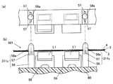
また、図21及び図22に示すように、単数又は複数の位置センサーは治具60に配置されている。位置センサーは、パイロット穴310の位置を認識してホログラム感材の島状部19の位置に対応する光学基材L1の傾斜面101における所定の位置の位置決めをすることができる。なお、位置センサーは、パイロット穴310の位置が認識することができる位置に配置することができれば、治具60の上部に設けなくともよい。
Further, as shown in FIGS. 21 and 22, the single or plural position sensors are arranged in the
位置センサーには、光型、超音波型、磁力型が挙げられる。この位置センサーは、ある特定の波長を発振するセンサー発振部55a1と発振した特定の波長を受信するセンサー受信部55b1とから構成されている。
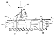
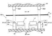
例えば、図21に貼付機構50bを示す。貼付機構50bの位置決め固定機構501bは、パイロットピン311c2,311c2を治具60に配置するとともに複数の位置センサーを治具60上に配置する。位置センサーは、パイロット穴310の位置を認識してホログラム感材の島状部19の位置に対応する光学基材L1の傾斜面101における所定の位置の位置決めをする。さらに、パイロットピン311c2,311c2は、対応するパイロット穴310,310に挿入する。パイロットピン311c2、位置センサーはそれぞれ単数でもよい。
Examples of the position sensor include an optical type, an ultrasonic type, and a magnetic type. This position sensor includes a sensor oscillation unit 55a1 that oscillates a specific wavelength and a sensor reception unit 55b1 that receives the oscillated specific wavelength.
For example, FIG. 21 shows a pasting mechanism 50b. The positioning and
パイロットピン311c2の先端部58c1には、センサー発振部55a1が設けられている。一方、シート上方である支持板61には、センサー受信部55b1が設けられている。このセンサー受信部55b1は、センサー発振部55a1から発振された特定の波長がパイロット穴310を通過して受信できる位置に配置する。
なお、センサー受信部55b1を支持板61に設けず、シートに反射した特定の波長を受信するようにパイロットピン311c2の先端部58c1に設けてもよい。また、センサー発振部55a1をパイロットピン311c2に設けずに、パイロットピン311c2の周辺であって治具60の上部に設けてもよい。
A sensor oscillating portion 55a1 is provided at the front end portion 58c1 of the pilot pin 311c2. On the other hand, a sensor receiver 55b1 is provided on the
The sensor receiver 55b1 may not be provided on the
位置センサーを設けることによって、位置センサーからの情報に基づいて制御部が積層シート5のパイロット穴310の位置を認識し、光学基材L1が配置された治具60の長手方向及び/又は幅方向の移動を制御し、パイロット穴310の位置決めや固定をする。
例えば、パイロットピン311c及び光学基材L1を配置した治具60の場合には、パイロット穴310の下方にパイロットピン311cが正確に配置されるように長手方向及び/又は幅方向に移動し、治具60が上方に移動してパイロットピン311cがパイロット穴310に挿入する。挿入後、ホログラム感材の島状部を光学基材L1の傾斜面101に貼付けする。貼付後、治具60が下方に移動し、パイロットピン311cがパイロット穴310から離脱をする。
By providing the position sensor, the control unit recognizes the position of the
For example, in the case of the
また、図22に貼付機構50cを示す。貼付機構50cの位置決め固定機構501cは、パイロット穴310を位置決めするとともに固定する先端部58aを設けずに位置センサーであるセンサー発振部55a1を治具60に設けてもよい。位置決めは、位置センサーから送信された情報に基づき制御部が治具60とシートとの位置を調整する。調整することによってホログラム感材の島状部19を光学基材L1の傾斜面101における所定の位置に位置決めをし、貼付ローラ51によってホログラム感材の島状部19を光学基材L1の傾斜面101に貼付ける。
FIG. 22 shows a pasting mechanism 50c. The positioning and
また、貼付ローラ51の形状は特に限定されないが、ホログラム感材の島状部の中央から光学基材L1の傾斜面101に貼付が行いやすい太鼓形状が好ましい。ホログラム感材と傾斜面101との間の生じる気泡などを低減することができる。
また、貼付ローラ51のローラの硬度は、特に限定されないが、ホログラム感材が押圧によって損傷しない程度の硬度が好ましい。例えば、硬度の柔らかい天然ゴム、合成ゴムやスポンジ状の合成樹脂などである。
Further, the shape of the sticking
Further, the hardness of the roller of the sticking
(f)第2剥離機構
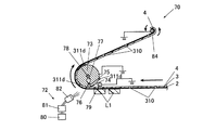
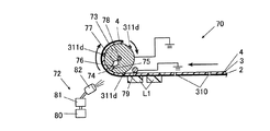
図23から図25に第2剥離機構70の概略図を示す。
第2剥離機構70は、除電手段を設けた剥離機構であり、第1剥離機構30の剥離ローラ33、接地した導電性部材39、除電流体噴付け機32、巻取りローラ44の配置が異なるのみであって、第1剥離機構30と同様の構成及び機能を有している。
第2剥離機構70には、剥離ローラ73、導電性部材79、巻取りローラ84などから構成されている。さらに剥離ローラ73には、吸引孔74、吸引通路75、ローラ軸78、吸引通路75、集合吸引通路77及び逆止弁76などが設けられている。
(F) 2nd peeling mechanism The schematic of the
The
The
剥離ローラ73の表面に、積層シート5に形成されたパイロット穴310に対応し、嵌合するパイロットピン311d設けられていることが好ましい。また、パイロット穴310の位置の認識に、パイロットピン311dの他に、位置センサーなどを用いてもよい。 これらパイロットピン311d及び/又は位置センサーによって、ホログラム感材シートに設けた前記パイロット穴の位置の認識をし、前記パイロット穴に対応するパイロットピンを前記パイロット穴に挿入して他方の保護シートを固定し、固定した前記他方の保護シートの外側面から巻取りローラで巻取ることが好ましい。
It is preferable that a
他方の保護シートであるベースシート4及びホログラム感材の梯子状部18をホログラム感材の島状部19から剥離する際に、光学基材L1の傾斜面101に貼り付けたホログラム感材の島状部19のズレ、ブレなどが低減するためである。
除電流体噴付け機72には、除電流体発生器80、ファン81及び噴付け口82などから構成されている。
When the
The current
なお、第1剥離機構は、吸引する機構を設けず、ホログラム感材の島状部19から他方の保護シートであるベースシート4及びホログラム感材の梯子状部18を剥離することができる。除電手段として、剥離ローラ73、導電性部材79、除電流体噴付け機72が設けられている。
また、図24に示すように、巻取りローラ84を設けず、ホログラム感材の島状部19から他方の保護シートであるベースシート4を離間し、巻き取るように剥離ローラ73が除電手段として機能してもよい。
In addition, the 1st peeling mechanism can peel the
Further, as shown in FIG. 24, the take-up
(g)露光機構
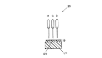
図26及び図27に露光機構90についての概略を示す。
露光機構90は、レーザ露光部などから構成されている。レーザ露光部には、ホログラム感材の島状部19に干渉縞を露光する赤緑青(RGB)のレーザ光を出射するレーザ発振器911,912,913及びレーザ発振器911,…からのレーザ光をホログラム感材の島状部19の所定位置で所定の波長のレーザ光で露光するための反射鏡、シッター、可変ビームスプリッタ、反射鏡などが設けられている。
(G) Exposure mechanism FIGS. 26 and 27 show an outline of the
The
可変ビームスプリッタ913,923,933は、レーザ光源を設けるレーザ発振器911,912,913からのレーザ露光の光軸上に配置されている。さらにこの可変ビームスプリッタ913,923,933は、レーザ光を参照光RGB1と物体光RGB2とに分離を行う。この参照光RGB1及び物体光RGB2が照射される光学基材L1の傾斜面101に貼り付けられているホログラム感材の島状部19をそれぞれ遮断するシャッター961,962を設けている。
The
参照光R1,G1,B1の光路には、ダイクロイックミラー941,942及び参照光R1,G1,B1の進行方向を変える全反射ミラー943,944,945が配置されている。ダイクロイックミラー941,942は、参照光R1、G1,B1を参照光RGB1に色合成し、全反射ミラー945を介してホログラム感材に入射する。
また物体光R2,G2,B2の光路には、ダイクロイックミラー946,947及び物体光R2,G2,B2の進行方向を変える全反射ミラー948,949が配置されている。ダイクロイックミラー946,947は、物体光R2,G2,B2を物体光RGB2に色合成し、全反射ミラー949を介してホログラム感材に入射する。
Dichroic mirrors 941, 942 and total reflection mirrors 943, 944, 945 for changing the traveling direction of the reference light R1, G1, B1 are arranged in the optical path of the reference light R1, G1, B1. The dichroic mirrors 941 and 942 color-synthesize the reference light R1, G1, and B1 with the reference light RGB1, and enter the hologram photosensitive material via the
Further,
レーザ発振器911は、赤色用レーザ光として647nm程度の波長を有するものが良好であり、例えば、Krレーザなどを用いることができる。レーザ発振器921は、緑色用レーザ光として532nm程度の波長を有するものが良好であり、例えば、YAGレーザなどを用いることができる。レーザ発振器931は、青色用レーザ光として447nm程度の波長を有するものが良好であり、例えば、Arレーザなどを用いることができる。
The
(h)現像機構
現像機構は、UV照射部及びベイク処理部などから構成されている(図示せず)。UV照射部には、UV、水銀灯、ブラックライト、蛍光灯、ダイオードなどの照射機が備えられている。照射機による照射によってホログラム感材の島状部19を安定してホログラム素子100に形成するとともに光学基材L1の傾斜面101とホログラム感材の島状部19とを接着剤などで固定するためである。ベイク処理部には、バインダーに存在する揮発性物質を揮発するとともに接着剤を用いてホログラム感材の島状部19と光学基材L1の傾斜面101とを固定するために一定温度を維持する恒温器が設けられている。
(H) Development Mechanism The development mechanism is composed of a UV irradiation unit, a bake processing unit, and the like (not shown). The UV irradiation unit is equipped with irradiation machines such as UV, mercury lamp, black light, fluorescent lamp, and diode. In order to stably form the island-shaped
ホログラム光学基材形成工程及びホログラム素子形成工程の作用について説明する。
(a)積層シート形成機構は、ジャンボロール体5A、ロールケーキ状に巻かれているパンケーキ状、帯状積層シート5Bを形成する。
(b)穿孔工程について図5及び図6を参照して説明する。
移送機構は積層シート5を穿孔機構300に移送する。固定板302及び固定台304は、積層シート5を挟むように上下に移動し、積層シート5を固定する。固定後、摺動機構の駆動が支持体303に伝達されて突起部301が上方向に内部孔305を摺動する。突起部301が積層シート5を穿孔することによってパイロット穴310が積層シートに形成する。形成後、固定板302及び固定台304が開く。移送機構がパイロット穴310を形成した積層シート5を移送する。
The operation of the hologram optical substrate forming step and the hologram element forming step will be described.
(A) The laminated sheet forming mechanism forms a
(B) The perforation process will be described with reference to FIGS.
The transfer mechanism transfers the
(c)切断工程について図7から図12を参照して説明する。
図7及び図8に示すように、移送機構は積層シート5を切断機構9aに移送する。積層シート5に形成されたパイロット穴310にパイロットピン311aが対応し、嵌合する。支持ローラ12が回転することによって鍔部13から切込みローラ11が回転する。切込みローラ11と支持ローラ12との回転によって、移送された積層シート5は、支持ローラ12と切込みローラ11との隙間を通過する。通過する際に、切込み刃15は、積層シート5の一方の保護シートの厚さ方向から所定の深さまで切込みを入れ、ホログラム感材シート2にホログラム感材の島状部19と梯子状部18とを形成する。
(C) The cutting process will be described with reference to FIGS.
As shown in FIGS. 7 and 8, the transfer mechanism transfers the
調整部14は、移送された積層シート5の厚さ寸法に応じながら切込みローラ11の鍔部13の直径及び切込み刃台の上下位置を調整する。これにより、切込み刃15の先端を保護シートの所定の厚さ寸法の深さまで切込みを入れることができる。この切込み刃15によって、ホログラム感材の島状部19の輪郭線に沿って切り込まれた半切断部20及び非切断部21を積層シート5に形成することができる。
The adjusting
なお、切断機構9bも、切込み板11bを除いて上記と同様の作用、効果である。積層シート5のパイロット穴310にパイロットピン311a2が対応し、嵌合する。切込み刃15bによって切込みが入れられる。この切込みによって、島状部19と梯子状部18とが形成される。
The
切込み刃15を変更することによって、島状部19の形状を変更することができ、また、半切断部20の形成を変更することができる。また、パイロットピン311a間の切込み刃15の個数によって、パイロット穴310からいずれか一方に隣接するパイロット穴310までの間に所定の個数の島状部19を形成する。
By changing the
このとき、図9aの場合には、半切断部20は、ホログラム感材の島状部19の輪郭線に沿って連続するように切断して形成される。図9bの場合には、半切断部20は、ホログラム感材の島状部19の輪郭線に沿って断続するミシン目状に切断して形成される。図9cの場合には、半切断部20は、ホログラム感材の島状部19の輪郭線に沿って半切断部20における積層シート5の長手方向にあるいずれか一方の一辺に非切断部21を設けて形成される。
At this time, in the case of FIG. 9 a, the half-
さらに、切込みローラ11を連続的に回転させる、又は複数の切込み刃15を設ける場合には、積層シート5の長手方向に半切断部20を所定の間隔を置いて複数形成することもできる。
半切断部20が形成された積層シート5は、移送装置によって第1剥離装置に移送される。
Further, when the cutting
The
(c)第1剥離工程について図13から図16を参照して説明する。
移送機構は、ホログラム感材の島状部19が下方向に形成された積層シート5を第1剥離機構30に移送する。剥離ローラ33は、保護シートの一方の剥離シートであるカバーシート1の外面側が吸引孔34に接し、吸引ポンプが動作して集合吸引通路37及び吸引通路35は真空状態になり、カバーシート1の外面側を吸引孔34によって吸引する。このとき、パイロットピン311bが設けられている場合には、保護シートであるベースシート4に形成されたパイロット穴310にパイロットピン311bが対応し、嵌合する。
(C) A 1st peeling process is demonstrated with reference to FIGS.
The transfer mechanism transfers the
このとき、剥離ローラ33はローラ軸38を中心に回転することによって、吸引して密着するカバーシート1をホログラム感材シート2から引き離し、離間させる方向に保護シートであるカバーシート1を誘導する。引っ張るための装置である巻取りローラ44は、誘導されたカバーシート1の末端部から巻取りを開始する。巻取りローラ44が回転することによって、カバーシート1がホログラム感材シート2から剥離される。特に、図7cの場合には、一方の保護シートであるカバーシート1を非切断部21側から積層シート5の長手方向に沿って剥離することが好ましい。
At this time, the peeling
保護シートの剥離時に剥離部に発生する静電気の除電を行う除電工程として、接地した剥離ローラ33、巻取りローラ44及び導電性部材39と除電流体噴付け機32とを用いて行う。なお、剥離ローラ33及び巻取りローラ44は、導電性部材39と同様の機能、作用を有しており、導電性部材39に含まれる。
保護シートの剥離時に接地された剥離ローラ33、巻取りローラ44及び導電性部材39は、保護シートのカバーシート1の剥離時において剥離部に近傍する保護シートであるカバーシート1又はベースシート4の外面側に接触して除電する。
As a static elimination process for eliminating static electricity generated in the peeling portion when the protective sheet is peeled off, the
The peeling
また、除電流体噴付け機32は、除電流体発生器40により除電流体を発生させ、ファン41により流速を調整し、噴付け口42より、除電流体を一方の保護シートであるカバーシート1の剥離時において剥離部に近傍する保護シートであるカバーシート1又はベースシート4、及び/又はホログラム感材シート2に対して噴きつける。このことによって、シート剥離時の静電気の発生を軽減すとともに剥離ローラ33の剥離を補助することができる。
In addition, the current removal
なお、図15に示すように、巻取りローラ44を設けず、巻取りを開始する端部を接着や直接固定などを行って剥離ローラ33に固定し、剥離ローラ33の回転によって、除電を行いながら積層シート5から保護シートであるカバーシートを離間し、巻取ることができる。
As shown in FIG. 15, the winding
(d)貼付工程について図17から図22を参照して説明する。
移送機構は、ホログラム感材の島状部19及び梯子状部18を他方の保護シートであるベースシート4に付着させたままの状態で貼付機構50に移送する。ホログラム感材の島状部19のみが光学基材L1の傾斜面101に貼り付ける位置に配置する。
(D) A sticking process is demonstrated with reference to FIGS.
The transfer mechanism transfers the island-shaped
配置後、治具60が上に移動し、パイロットピン311c,311cがパイロット穴310に挿入し、位置決め及び/又は固定する。位置決めによって、ホログラム感材の島状部19を光学基材L1の傾斜面101における所定の位置に貼り付けることができる。また、固定されることによって、ホログラム感材の島状部19を光学基材L1の傾斜面101に貼り付ける際に、ホログラム感材のノビを軽減することができる。
After the placement, the
位置決め及び/又は固定後、ベースシート4の上方にある貼付ローラ51がベースシート4方向からホログラム感材の島状部19及び光学基材L1の傾斜面101を密着するように押圧しながら順逆に転動する。このことによって、ホログラム感材の島状部19と光学基材L1の傾斜面101とが密着する。貼付ローラ51は、支持部材52によって支持され、積層シート5への押圧を弾性部材53が調整し、貼付ローラ51の順逆回転をローラ軸54が調整する。貼付後、治具60が下に移動し、パイロットピン311c,311cがパイロット穴310から離脱する。
After positioning and / or fixing, the sticking
なお、位置センサーを設けている場合には、センサー発振部55a1とセンサー受信部55b1によってパイロット穴310の位置を認識する。位置センサーによって得た情報を制御部に送信し、制御部によって治具60及びシートを移送し、パイロットピン311c2,311c2がパイロット穴310に挿入できる位置に長手方向及び/又は幅方向に移動しながら調整する。調整後、パイロットピン311c2,311c2がパイロット穴310に挿入し、位置決め及び固定する。
When a position sensor is provided, the position of the
また、パイロットピン311c3は、位置センサーによってパイロット穴310の位置を認識しながら、制御部によって治具60及びシートを長手方向及び/又は幅方向に移動しながら調整する。
位置センサーによって、ホログラム感材の島状部19を光学基材L1の傾斜面101における所定の位置により正確に貼り付けることができる。
The pilot pin 311c3 is adjusted while moving the
With the position sensor, the island-shaped
(e)第2剥離工程について図23から図25を参照にして説明する。
移送機構は、光学基材L1の傾斜面101にホログラム感材の島状部19が接着し、カバーシート1が剥離された積層シートを移送する。剥離ローラ73は、ベースシート4の外面側が吸引孔34に接し、吸引ポンプが作動して集合吸引通路77及び吸引通路75は真空状態となり、ベースシート4の外面側を吸引孔74によって吸引する。
このとき、パイロットピン311dが設けられている場合には、保護シートであるベースシート4に形成されたパイロット穴310にパイロットピン311dが対応し、嵌合する。
(E) A 2nd peeling process is demonstrated with reference to FIGS. 23-25.
The transfer mechanism transfers the laminated sheet from which the island-shaped
At this time, when the
剥離ローラ73は、ローラ軸78を中心にベースシート4の外面側を吸引しながら回転することによって、ベースシート4とベースシート4に接着するホログラム感材の梯子状部18とを光学基材L1の傾斜面101に接着するホログラム感材の島状部19のある島状部19から引き離し、離間させる方向にベースシート4及びホログラム感材の梯子状部18を誘導する。
The peeling
引っ張るための装置である巻取りローラ84は、誘導されたベースシート4の末端部から巻取りを開始する。巻取りローラ84が回転することによって、ベースシート4及びホログラム感材の梯子状部18がホログラム感材の島状部19から剥離される。このとき、除電流体噴付け機72は、離間させる方向の剥離したシート面及びホログラム感材の梯子状部18と島状部19との切断面の間に除電流体を噴付ける。
特に、図9cの場合には、ホログラム感材の島状部19を光学基材L1に貼り付けた後、非切断部21側の反対側から長手方向に沿って保護シートであるベースシート4及び梯子状部18と島状部19とを剥離する。
The take-up
In particular, in the case of FIG. 9c, after the island-shaped
このとき、上記第1剥離工程と同様に除電工程が、保護シートの剥離時に接地された剥離ローラ73、巻取りローラ84及び導電性部材79は、保護シートのベースシート4の剥離時において剥離部に近傍する保護シートであるベースシート4の外面側に接触する。除電流体噴付け機72は、除電流体を他方の保護シートであるベースシート4の剥離時において剥離部に近傍する保護シートであるベースシート4、及び/又はホログラム感材の島状部19及び梯子状部18に対して噴付けをする。
At this time, as in the first peeling step, the static elimination step is performed when the peeling
これによって、ホログラム感材の島状部19とベースシート4及びホログラム感材の梯子状部18とが剥離することができ、ホログラム感材及びバリアシートの島状部19が傾斜面101に接着した光学基材L1が得られる。
Thereby, the island-shaped
なお、図24に示すように上記第1剥離工程と同様に、巻取りローラ84を設けず、剥離ローラ73によって除電を行いながらホログラム感材の梯子状部18とベースシート4とを離間し、巻取ることができる。
As shown in FIG. 24, similarly to the first peeling step, the winding
(f)露光工程及び(g)現像工程について図26を及び図27参照にして説明する。
露光機構90は、光学基材L1に接合しているホログラム感材の島状部19にレーザ発振器911,912,913から出射した参照光RGB1と物体光RGB2によってレーザ露光を行う。
レーザ発振器911,912,913から出射したレーザ光を可変ビームスプリッタ913,923,933により参照光R1,G1,B1と物体光R2,G2,B2とに分光する。参照光R1,G1,B1は、ダイクロイックミラー941,942及び全反射ミラー943,944,945によって参照光RGB1とし、ダイクロイックミラー946,947及び全反射ミラー948,949によって物体光RBG2とし、ホログラム感材の島状部19の主面に入射する。
これによって、ホログラム感材の島状部19上の所定の位置に参照光と物体光との干渉によって生じる干渉縞がホログラム感材の島状部19の感光層に屈折率の変化として記録される。
The (f) exposure step and (g) development step will be described with reference to FIGS.
The
The laser beams emitted from the
As a result, interference fringes caused by the interference between the reference light and the object light are recorded on the photosensitive layer of the island-shaped
現像機構は、干渉縞を形成したホログラム感材の島状部19にさらにUVなどの照射部によってUVなどを照射し、ホログラム感材を現像する。さらに、ホログラム感材シート付き光学基材L1をベイク処理器内で、100℃程度で12時間から36時間の間、ベイク処理を行って、ホログラム感材のバインダーなどから揮発性有機物質を揮発させて、ホログラム素子100とする。
このことによって、WDやHMDに用いられる接眼光学レンズであるホログラム光学基材L100を形成する。
The developing mechanism further irradiates UV or the like to the island-shaped
By this, the hologram optical base material L100 which is an eyepiece optical lens used for WD and HMD is formed.
以上のことより、以下の作用効果が得られる。
積層シートにパイロット穴を形成し、生産工程中にパイロットピンを設けることによって、工程での位置決めを容易にすることができる。特に、剥離工程や貼付工程などで正確にホログラム感材の島状部を第1光学基材の傾斜面上における所定の位置にズレを生じさせず、貼り付けることができる。また、パイロットピンを設けてパイロット穴を固定するため、ホログラム感材の島状部にノビが生じることなく、貼り付けることができる。さらに、ホログラム感材への損傷が低減することができる。精度の高いホログラム素子を形成することができるので、ホログラム光学基材の生産効率が向上する。
From the above, the following effects can be obtained.
Positioning in the process can be facilitated by forming pilot holes in the laminated sheet and providing pilot pins during the production process. In particular, it is possible to attach the island-shaped portion of the hologram sensitive material accurately at a predetermined position on the inclined surface of the first optical base material without causing a shift in the peeling process or the pasting process. Moreover, since the pilot pin is provided and the pilot hole is fixed, it can be pasted without causing nono on the island-shaped portion of the hologram photosensitive material. Furthermore, damage to the hologram sensitive material can be reduced. Since a highly accurate hologram element can be formed, the production efficiency of the hologram optical substrate is improved.
また、半切断部を形成したので、一方の保護シートをホログラム感材シートから剥離する際に、一方の保護シートをすべて剥離しつつ、他方の保護シート側に光学基材に貼付け可能な状態のホログラム感材の島状部を残存させることができる。また、光学基材にホログラム感材の島状部部分を貼付け後、他方の保護シートを剥離する際に、不要となったホログラム感材の梯子状部を取り除きながらホログラム感材の島状部のみを第1光学基材の傾斜面に貼り付けることができる。 In addition, since the semi-cut portion is formed, when one protective sheet is peeled off from the hologram photosensitive material sheet, all the one protective sheet is peeled off while the other protective sheet can be attached to the optical substrate. The island-shaped portion of the hologram sensitive material can be left. Also, after pasting the island-shaped portion of the hologram photosensitive material on the optical substrate, when peeling off the other protective sheet, only the island-shaped portion of the hologram sensitive material is removed while removing the ladder-shaped portion of the hologram sensitive material that is no longer needed Can be attached to the inclined surface of the first optical substrate.
半切断部を形成することによって、柔らかなホログラム感材をシワや変形などを生じさせることなく島状に切り出しができる。また、貼付け後、第1光学基材の傾斜面に接着しているホログラム感材の島状部19にウキが生じることなく、ホログラム光学素子を形成することが可能となる。保護シートの剥離と同時にホログラム感材の島状部を形成することができるため、生産工程の簡略化が可能となり、生産効率を向上させることができる。
By forming the half-cut portion, the soft hologram sensitive material can be cut into islands without causing wrinkles or deformation. In addition, it is possible to form a hologram optical element without sticking the island-shaped
また、露光前のホログラム感材の島状部が損傷などの生じやすい素材であっても第1光学基材の所定の位置に貼付けることができる。さらに、第1光学基材を固定することによって、正確な位置にレーザ露光を行って干渉縞を形成することができるので、ホログラム素子の完成率を上げることができ、ホログラム光学基材の生産効率が向上する。 Further, even if the island-shaped portion of the hologram sensitive material before exposure is a material that is easily damaged, it can be pasted to a predetermined position of the first optical substrate. Furthermore, by fixing the first optical substrate, it is possible to form interference fringes by performing laser exposure at an accurate position, so that the completion rate of the hologram element can be increased and the production efficiency of the hologram optical substrate is increased. Will improve.
また、設けられた除電手段によって剥離する際に発生する静電気を低減することができるので、剥離の際に生じやすい帯電性のあるホログラム感材シートのシワ、タワミまたは損傷などを低減することができる。さらに、静電気による発光の影響によってホログラム感材が感光などによるホログラム感材の品質の低下を防ぎ、生成されるホログラム素子の品質の低下を防ぐことができる。 In addition, since static electricity generated when peeling by the provided static eliminating means can be reduced, wrinkles, wrinkles, damage, etc. of the charged hologram sensitive sheet that are likely to occur during peeling can be reduced. . Furthermore, the hologram sensitive material can prevent deterioration of the quality of the hologram sensitive material due to exposure due to the influence of light emission due to static electricity, and the quality of the generated hologram element can be prevented from being deteriorated.
ホログラム感材シートに切断を行ってホログラム感材の島状部を切り出しすることによって、保護シートを剥離する際のホログラム感材のシワ、タワミなどを低減することができ、ホログラム感材の島状部を正確に第1光学基材の傾斜面に貼り付けることができ、さらに正確な位置にレーザ光することができる。このため、第2光学基材で一体化する第1光学基材から形成されるホログラム光学基材に精度のよいホログラム素子を形成することができるという効果を奏する。ホログラム光学基材の歩留まりが向上することによって、ホログラム素子内蔵レンズの生産性を向上することができる。 By cutting the hologram sensitive material sheet to cut out the island-shaped portion of the hologram sensitive material, it is possible to reduce wrinkles, wrinkles, etc. of the hologram sensitive material when peeling off the protective sheet. The portion can be accurately affixed to the inclined surface of the first optical substrate, and laser light can be emitted at a more accurate position. For this reason, there exists an effect that a highly accurate hologram element can be formed in the hologram optical base material formed from the 1st optical base material integrated with a 2nd optical base material. By improving the yield of the hologram optical substrate, the productivity of the hologram element built-in lens can be improved.
(3)一体化工程
以下、図1、図28からを参照しながら、ホログラム光学基材L100を光学基材L2に組み合わせて一体化する一体化工程について説明する。
一体化工程は、第1光学基材である光学基材L1の外形形状に対応する第2光学基材である光学基材L2に形成する形成工程、光学基材L2にホログラム光学基材を接着する接着工程などから構成されている。
(3) Integration Step Hereinafter, an integration step for combining the hologram optical base material L100 with the optical base material L2 and integrating them will be described with reference to FIGS.
The integration step is a forming step of forming the optical substrate L2 as the second optical substrate corresponding to the outer shape of the optical substrate L1 as the first optical substrate, and bonding the hologram optical substrate to the optical substrate L2. It consists of a bonding process and the like.
光学基材形成工程は、上記の(2)光学基材形成工程に述べている。接着工程は、ホログラム光学基材L100のホログラム素子100の表面に接着するバリアシート3を剥離する第3剥離工程、接合面102又は/及び接合面105に接着剤、特に紫外線硬化型接着剤を塗布する接着剤塗布工程と、ホログラム光学基材L100の接合面102と光学基材L2との接合面105で接合するレンズ接合工程と、接着剤を硬化させ、レンズ表面をクリーニングする接着剤硬化工程となどから構成されている。
The optical substrate forming step is described in the above (2) Optical substrate forming step. The adhering step is a third exfoliating step for exfoliating the
接着剤硬化機構(図示せず)には、ホログラム光学基材L100が嵌合した光学基材L2を固定する光学レンズ支持部、接着剤を硬化させるための接着剤硬化照射部、温度制御部、これらを制御する制御部などが設けられている。
接着剤硬化照射部には、ホログラム光学基材L100が嵌合した光学基材L2の上方又は/及び下方に光源が配置されている。この光源として、低圧又は高圧水銀灯、紫外線ランプ、ブラックライト、EEFL(External Electrode Fluorescent Lamp)、自然光などが挙げられる。また、温度制御部には、ベイク処理するための恒温器などが挙げられ、この恒温器内には、接着剤硬化照射部が配置されている。制御部、光源の照射時間、照射量、照射強度、加温時間、温度範囲などを制御することによって接着剤の硬化を調整している。
An adhesive curing mechanism (not shown) includes an optical lens support unit for fixing the optical substrate L2 fitted with the hologram optical substrate L100, an adhesive curing irradiation unit for curing the adhesive, a temperature control unit, A control unit or the like for controlling these is provided.
In the adhesive curing irradiation section, a light source is disposed above and / or below the optical substrate L2 into which the hologram optical substrate L100 is fitted. Examples of the light source include a low-pressure or high-pressure mercury lamp, an ultraviolet lamp, a black light, an EEFL (External Electrode Fluorescent Lamp), and natural light. The temperature control unit includes a thermostat for baking, and an adhesive curing irradiation unit is disposed in the thermostat. The curing of the adhesive is adjusted by controlling the control unit, the irradiation time of the light source, the irradiation amount, the irradiation intensity, the heating time, the temperature range, and the like.
接着剤としては、光学基材の光屈折率と同じ屈折率を示すものであればよい。この中で光硬化型接着剤、特に紫外線硬化型接着剤が好ましい。紫外線などの光エネルギ−を照射することによって硬化するとともに、光学基材L1及び光学基材L2の光屈折率の範囲のものを選択することができるためである。また、紫外線硬化型接着剤は、光学基材L1及び光学基材L2の表面を侵食しにくいため好ましい。特に、アクリル系のPMMA、ポリカーボネイトのPCが光学基材L1及び光学基材L2の屈折率の範囲に含まれるため好ましい。例えば、Norland社製品NOAシリーズ又はEMI社製品OPTOCAST3400シリーズなどが挙げられる。 Any adhesive may be used as long as it exhibits the same refractive index as the optical refractive index of the optical substrate. Among these, a photocurable adhesive, particularly an ultraviolet curable adhesive is preferable. This is because curing can be performed by irradiating light energy such as ultraviolet rays, and the optical base material L1 and the optical base material L2 in the range of the optical refractive index can be selected. Further, the ultraviolet curable adhesive is preferable because it hardly erodes the surfaces of the optical substrate L1 and the optical substrate L2. In particular, acrylic PMMA and polycarbonate PC are preferable because they are included in the refractive index range of the optical substrate L1 and the optical substrate L2. For example, Norland product NOA series or EMI product OPTOCAST3400 series.
紫外線硬化型接着剤としては、重合性モノマーとして、ビニル系、アクリル系、又はメタクリル系などで分子内に少なくとも1つ以上二重結合を有するものである。具体的には単官能モノマーとしてアクリル酸、メタクリル酸の他にアクリル酸メチル、アクリル酸エチルなどのアルキルアクリル酸エステル類、メタクリル酸メチル、メタクリル酸ブチル若しくはそれらのヒドロキシ化合物なども含むアルキルメタクリル酸エステル類、又はスチレンモノマー、アクリルニトリルモノマーなどである。
また、多官能モノマーとしてエチレングリコールジメタクリレートなどのアクリル系やジアリルフタレートなどのアリル系などである。これらの多官能モノマーは重合硬化過程で架橋構造が得られ接着部の耐久性や熱安定性を改良することができるものである。
The ultraviolet curable adhesive is a polymerizable monomer such as vinyl, acrylic, or methacrylic that has at least one double bond in the molecule. Specifically, as a monofunctional monomer, alkyl methacrylate including alkyl acrylate such as methyl acrylate and ethyl acrylate, methyl methacrylate, butyl methacrylate or hydroxy compounds thereof, in addition to acrylic acid and methacrylic acid. Or styrene monomer, acrylonitrile monomer and the like.
Examples of the polyfunctional monomer include acrylics such as ethylene glycol dimethacrylate and allyls such as diallyl phthalate. These polyfunctional monomers can obtain a crosslinked structure in the polymerization and curing process, and can improve the durability and thermal stability of the bonded portion.
紫外線硬化型接着剤に添加される光重合剤としては、通常の紫外線によってラジカル重合できるものであればよく、アセトフェノン系、ネンゾフェニル系、ベンゾイン系、チオキサンソン系、アジルフォスフィンオキサイド系の化合物が挙げられる。 The photopolymerization agent added to the ultraviolet curable adhesive is not particularly limited as long as it can be radically polymerized by ordinary ultraviolet rays. .
なお、接合強度を増すために、光学基材L1aの接合面102b及び102cにヤゲンを形成してもよい。このとき、光学基材L2aの接合面102b及び102cには、ヤゲンに対応する凹部が形成される。ヤゲンを形成する際の光学基材L1aは、ヤゲン形成時に接合面102b及び102cが切削りができるように予め大きく形成されていることが好ましい。光学基材L1aには、切削りによって光学基材L2に対応できる接合面が形成される。
In order to increase the bonding strength, bevels may be formed on the bonding surfaces 102b and 102c of the optical substrate L1a. At this time, concave portions corresponding to bevels are formed on the
以下、(3)一体化工程の作用について説明する。
バリアシート剥離工程は、ホログラム光学基材L100のホログラム素子100の表面に接着するバリアシート3を剥離する。接着剤塗布工程は、ホログラム光学基材L100の接合面102又は/及び光学基材L2の接合面105に接着剤、特に紫外線硬化型接着剤を塗布する。レンズ接合工程は、光学基材L1を背面方向に移動し、ホログラム光学基材L100の接合面102と光学基材L2との接合面105で組み合わせて嵌合して接合する。接着剤硬化工程は、ホログラム光学基材L100が嵌合した光学基材L2のレンズ表面をクリーニングし、一定時間及び一定量の紫外線を接着剤が塗布されている嵌合した接合面に照射し、特に紫外線硬化型接着剤を硬化させる。
Hereinafter, the operation of the (3) integration step will be described.
In the barrier sheet peeling step, the
これによって、嵌合したホログラム光学基材L100の接合面102及び光学基材L2の接合面105が接着剤を介して接着することによって、図28に示すようなホログラム素子内蔵レンズ200を形成する。
As a result, the joint surface 102 of the fitted hologram optical base material L100 and the joint surface 105 of the optical base material L2 are bonded together via an adhesive, thereby forming the hologram element built-in
なお、光学基材切削り機構130によって、光学基材L1、ホログラム光学基材L100、光学基材L2の接合面102及び/又は接合面105に連通する凹部、微小凹部(梨粒状も含む)などを形成することができる。接着剤を均一に浸透させることができ、光学レンズ表面への接着剤のはみ出しを防ぐことができ、また接合面同士の接着力を強化することができる。
なお、光学基材切削り機構130を行わず、予め光学基材の射出成形金型や射出圧縮成形などの形成時に、光学基材L1及び/又は光学基材L2の接合面102及び/又は接合面105に凹部110を形成してもよい。
In addition, the optical base material cutting mechanism 130 causes the optical base material L1, the hologram optical base material L100, the concave surface communicating with the joint surface 102 and / or the joint surface 105 of the optical base material L2, a micro concave portion (including pear-shaped particles), and the like. Can be formed. The adhesive can be uniformly permeated, the adhesive can be prevented from protruding to the surface of the optical lens, and the adhesive force between the joint surfaces can be enhanced.
Note that the optical substrate L1 and / or the bonding surface 102 and / or bonding of the optical substrate L2 is not performed when the optical substrate L1 and / or the optical substrate L2 are formed in advance, without performing the optical substrate cutting mechanism 130. A
以上のことより、さらに、ホログラム光学基材を第2光学基材と接着剤を介して接合面同士で接合することによって、ホログラム素子内蔵レンズを形成することができる。一体化工程で、光学基材形成工程と接着工程を含むことによって、ホログラム光学基材と第2光学基材とを接着することによってホログラム素子内蔵レンズを形成することができる。 From the above, a hologram element built-in lens can be formed by further joining the hologram optical base material with the second optical base material at the joint surfaces via an adhesive. By including the optical substrate forming step and the bonding step in the integration step, the hologram element built-in lens can be formed by bonding the hologram optical substrate and the second optical substrate.
さらに、眼鏡フレーム、LCD表示部、コントローラ部を備えることによってWDやHMDとして使用することができる。このときに、保護シートを剥離するさいにホログラム感材にシワヤタワミが生じることなく、第1光学基材に貼り付けることができるので、ホログラム素子内蔵レンズを形成してとき、映像のヒズミや色ブレを低減することができる。 Furthermore, it can be used as a WD or HMD by including a spectacle frame, an LCD display unit, and a controller unit. At this time, when the protective sheet is peeled off, the hologram photosensitive material can be affixed to the first optical substrate without causing wrinkles. Therefore, when the hologram element built-in lens is formed, image distortion or color blur is generated. Can be reduced.
このように、ホログラム光学基材形成工程と一体化工程とを含むことによって、WDやHMDに使用できる精度の高いホログラム素子を形成しつつ、生産工程の簡略化が可能となり、ホログラム素子内蔵レンズの生産性を向上することができる。 Thus, by including the hologram optical substrate forming step and the integration step, it is possible to simplify the production process while forming a highly accurate hologram element that can be used for WD and HMD. Productivity can be improved.
50,50b,50c 貼付機構
57 シート支持体
58a,58b 先端部
60 治具
300 穿孔機構
310 パイロット穴
311c,311c2,311c3 パイロットピン
501,501b,501c 位置決め固定機構
502 ローラ貼付機構
50, 50b,
Claims (8)
前記保護シートの何れか一方の外側面から前記積層シートの厚さ方向にパイロット穴を長手方向及び/又は幅方向に一定間隔で穿孔する穿孔工程と、
前記積層シートの長手方向及び/又は幅方向に形成した前記パイロット穴の位置を認識し、
認識された前記パイロット穴の位置を基準に前記保護シートの何れか一方の外面側から前記積層シートの厚さ方向にホログラム感材の島状部の輪郭線に沿って切り込まれる半切断部を形成する切断工程と、
一方の保護シートを前記ホログラム感材シートから剥離する第1剥離工程と、
前記パイロット穴の位置を認識し、認識された前記パイロット穴の位置を基準に第1光学基材を配置した治具を移送し、
他方の保護シートに付着させた状態の前記ホログラム感材の島状部を前記ホログラム感材の島状部と対応する前記第1光学基材の傾斜面上における所定の位置に位置決めをし、
前記ホログラム感材の島状部を前記第1光学基材の傾斜面に貼付ける貼付工程と、
を含むことを特徴とするホログラム光学基材の製造方法。 Hologram optics for forming a hologram element by providing a laminated sheet formed in a sandwich-like shape with a hologram sensitive material sheet adhered to a pair of protective sheets so as to be peeled from each other, and cutting out a part of the hologram sensitive material into an island shape A method for manufacturing a substrate, comprising:
A drilling step of drilling pilot holes in the longitudinal direction and / or the width direction at regular intervals from the outer surface of any one of the protective sheets in the thickness direction of the laminated sheet;
Recognizing the position of the pilot hole formed in the longitudinal direction and / or the width direction of the laminated sheet;
A semi-cut portion cut along the contour line of the island-shaped portion of the hologram sensitive material in the thickness direction of the laminated sheet from the outer surface side of any one of the protective sheets on the basis of the recognized position of the pilot hole A cutting step to form;
A first peeling step of peeling one protective sheet from the hologram sensitive material sheet;
Recognizing the position of the pilot hole, and transferring a jig on which the first optical base material is arranged based on the recognized position of the pilot hole;
Positioning the island-shaped portion of the hologram sensitive material in a state attached to the other protective sheet at a predetermined position on the inclined surface of the first optical substrate corresponding to the island-shaped portion of the hologram sensitive material;
An attaching step of attaching the island-shaped portion of the hologram sensitive material to the inclined surface of the first optical substrate;
A method for producing a holographic optical substrate, comprising:
前記パイロット穴の位置に対応する、単数又は複数のパイロットピンを前記治具に配置し、
前記パイロットピンを対応する前記パイロット穴に挿入して前記位置決めをすることを特徴とする請求項1に記載のホログラム光学基材の製造方法。 Recognition of the position of the pilot hole in the pasting step,
One or more pilot pins corresponding to the positions of the pilot holes are arranged in the jig,
2. The method of manufacturing a hologram optical substrate according to claim 1, wherein the positioning is performed by inserting the pilot pin into the corresponding pilot hole.
単数又は複数の位置センサーを前記治具に配置し、
前記位置センサーに基づいて前記パイロット穴の位置を認識して前記位置決めをすることを特徴とする請求項1に記載のホログラム光学基材の製造方法。 Recognition of the position of the pilot hole in the pasting step,
Placing one or more position sensors on the jig,
2. The method of manufacturing a hologram optical substrate according to claim 1, wherein the positioning is performed by recognizing the position of the pilot hole based on the position sensor.
前記パイロット穴の位置に対応する、単数又は複数の前記パイロットピンを前記治具に配置するとともに単数又は複数の前記位置センサーを前記治具に配置し、
前記位置センサーに基づいて前記パイロット穴の位置を認識するとともに前記パイロットピンを対応する前記パイロット穴に挿入して前記位置決めをすることを特徴とする請求項1に記載のホログラム光学基材の製造方法。 Recognition of the position of the pilot hole in the pasting step,
One or more pilot pins corresponding to the position of the pilot hole are arranged in the jig and one or more position sensors are arranged in the jig,
2. The method for manufacturing a hologram optical substrate according to claim 1, wherein the position of the pilot hole is recognized based on the position sensor and the positioning is performed by inserting the pilot pin into the corresponding pilot hole. .
2つの前記ホログラム感材の島状部ごとに形成することを特徴とする請求項1から請求項4の何れか一項に記載のホログラム光学基材の製造方法。 The fixed interval for drilling the pilot hole in the longitudinal direction in the drilling step is:
It forms for every island-shaped part of the said two hologram sensitive materials, The manufacturing method of the hologram optical base material as described in any one of Claims 1-4 characterized by the above-mentioned.
前記島状部は、前記帯状積層シートの長手方向であって前記パイロット穴からいずれか一方に隣接する前記パイロット穴の間に所定の間隔をおいて単数又は複数形成することを特徴とする請求項1から請求項5の何れか一項に記載のホログラム光学基材の製造方法。 The laminated sheet is a belt-shaped laminated sheet formed in a belt shape,
The island-like part is formed in a longitudinal direction of the belt-like laminated sheet and is formed by one or a plurality at a predetermined interval between the pilot holes adjacent to one of the pilot holes. The method for producing a hologram optical substrate according to any one of claims 1 to 5.
前記ホログラム光学基材と第2光学基材とを一体化する一体化工程と、
を含むことを特徴とするホログラム素子内蔵レンズの製造方法。 A hologram optical substrate forming step of forming a hologram optical substrate in the method of manufacturing a hologram optical substrate according to any one of claims 1 to 7,
An integration step of integrating the hologram optical substrate and the second optical substrate;
A method for manufacturing a lens with a built-in hologram element, comprising:
Priority Applications (1)
| Application Number | Priority Date | Filing Date | Title |
|---|---|---|---|
| JP2005013028A JP2006201475A (en) | 2005-01-20 | 2005-01-20 | Method for producing hologram optical base material and method for producing lens with build-in hologram element |
Applications Claiming Priority (1)
| Application Number | Priority Date | Filing Date | Title |
|---|---|---|---|
| JP2005013028A JP2006201475A (en) | 2005-01-20 | 2005-01-20 | Method for producing hologram optical base material and method for producing lens with build-in hologram element |
Publications (1)
| Publication Number | Publication Date |
|---|---|
| JP2006201475A true JP2006201475A (en) | 2006-08-03 |
Family
ID=36959525
Family Applications (1)
| Application Number | Title | Priority Date | Filing Date |
|---|---|---|---|
| JP2005013028A Pending JP2006201475A (en) | 2005-01-20 | 2005-01-20 | Method for producing hologram optical base material and method for producing lens with build-in hologram element |
Country Status (1)
| Country | Link |
|---|---|
| JP (1) | JP2006201475A (en) |
-
2005
- 2005-01-20 JP JP2005013028A patent/JP2006201475A/en active Pending
Similar Documents
| Publication | Publication Date | Title |
|---|---|---|
| JP6598497B2 (en) | Liquid discharge head and manufacturing method thereof | |
| JP2009518675A (en) | Method for transferring micron-size pattern onto optical product, and optical product using the same | |
| JPWO2017216898A1 (en) | Endoscope optical unit manufacturing method, endoscope optical unit, and endoscope | |
| JP4639814B2 (en) | Method for manufacturing hologram optical substrate and method for manufacturing lens with hologram element | |
| JP2006178185A (en) | Method for manufacturing lens, method for manufacturing image display apparatus, device for manufacturing lens, and device for manufacturing image display apparatus | |
| CN112445114A (en) | Method for manufacturing optical element, and display device | |
| JP6216584B2 (en) | Sheet sticking device and sticking method | |
| JP2006187994A (en) | Method for joining optical lens | |
| JP2006176275A (en) | Sheet peeling device | |
| JP4622505B2 (en) | Method for generating hologram element | |
| JP2006201475A (en) | Method for producing hologram optical base material and method for producing lens with build-in hologram element | |
| JP4622506B2 (en) | Method for generating hologram element | |
| JPWO2006067997A1 (en) | Manufacturing method of lens with built-in hologram element | |
| EP3411742B1 (en) | Head-worn display optics comprising a multicomponent lens system | |
| CN114721081B (en) | Low-adhesion holographic film, preparation method thereof and application thereof in preparation of AR display element | |
| JPH11295680A (en) | Liquid crystal panel manufacturing method | |
| CN114005370B (en) | Bonding device and bonding method | |
| TWI579640B (en) | Thin-film mask, fitting aids, fitting and exposure device and fitting method for the thin-film mask pasted on a curved substrate | |
| JP2006178184A (en) | Method for sticking hologram sensitive material sheet | |
| JP2008137347A (en) | Multilayer film and image display device | |
| JP2004093899A (en) | Label sheet and label sticking method using same | |
| JP2006195073A (en) | Method of manufacturing lens with built-in hologram element | |
| JP2024178104A (en) | Method for manufacturing luminous needles by replicating microstructures | |
| JPH1020752A (en) | Holographic stereogram, method for producing the same, and holographic stereogram producing apparatus used therefor | |
| JP2007160775A (en) | Method for pasting hologram sensitive material |