JP2006199416A - Article carrying device - Google Patents
Article carrying device Download PDFInfo
- Publication number
- JP2006199416A JP2006199416A JP2005011986A JP2005011986A JP2006199416A JP 2006199416 A JP2006199416 A JP 2006199416A JP 2005011986 A JP2005011986 A JP 2005011986A JP 2005011986 A JP2005011986 A JP 2005011986A JP 2006199416 A JP2006199416 A JP 2006199416A
- Authority
- JP
- Japan
- Prior art keywords
- cam
- article
- transport
- input shaft
- unit
- Prior art date
- Legal status (The legal status is an assumption and is not a legal conclusion. Google has not performed a legal analysis and makes no representation as to the accuracy of the status listed.)
- Granted
Links
Images


Abstract
Description
本発明は、搬送部に振動を与えることによって搬送部の搬送路内を物品を搬送する物品搬送装置に関し、特に、直線状に規制された搬送路を有する搬送部を備えた物品搬送装置に関する。 The present invention relates to an article conveyance device that conveys an article in a conveyance path of a conveyance unit by applying vibration to the conveyance unit, and more particularly to an article conveyance device that includes a conveyance unit having a linearly regulated conveyance path.
従来、いわゆるバラ部品等の物品の搬送を行う物品搬送装置の一例として、物品を搬送する搬送面を振動させて、物品の搬送面に対する相対的な滑り及び跳躍現象を利用することにより、物品を搬送するように構成した振動フィーダが知られている。 Conventionally, as an example of an article conveying apparatus that conveys an article such as a so-called loose part, an article is manufactured by vibrating a conveying surface that conveys an article and utilizing a relative slip and jump phenomenon with respect to the conveying surface of the article. Vibration feeders configured to convey are known.
このような構成の振動フィーダを用いて物品供給ラインを構成するには、物品の貯蔵、整列、次工程への供給といった機能が必要になるため、一般には、物品を貯蔵するためのホッパと、物品を整列させるためのボウルフィーダと、物品を搬送するためのリニアフィーダ(振動フィーダ)とを組み合わせている。 In order to configure an article supply line using the vibratory feeder having such a configuration, functions such as storage, alignment, and supply to the next process of articles are required. Therefore, in general, a hopper for storing articles, A bowl feeder for aligning articles and a linear feeder (vibration feeder) for conveying articles are combined.
このような構成の物品供給ラインにおいては、ホッパに貯蔵した物品は、ホッパからボウルフィーダの貯蔵部に供給され、ボウルフィーダの貯蔵部から円周路に供給され、円周路を搬送されながら整列されて、ボウルフィーダからリニアフィーダの直線状の搬送路内に供給され、リニアフィーダの搬送路内を搬送されて、リニアフィーダに連続する次工程に供給される。 In the article supply line having such a configuration, articles stored in the hopper are supplied from the hopper to the storage section of the bowl feeder, supplied from the storage section of the bowl feeder to the circumferential path, and aligned while being conveyed in the circumferential path. Then, it is supplied from the bowl feeder into the linear conveyance path of the linear feeder, is conveyed through the conveyance path of the linear feeder, and is supplied to the next process continuous to the linear feeder.
ここで、ボウルフィーダによって物品の整列を行うのは、ボウルフィーダは、貯蔵能力に優れ、中央部に貯蔵部が位置しているため、物品の整列の際の判別によってラインから排除された物品を再びラインに戻す循環路を構成し易いからである。また、整列された物品をリニアフィーダによって搬送するのは、物品供給ラインを構成する場合、直線的に物品を供給した方が搬送効率がよく、搬送中のトラブルも少ない等の利点があるからである。 Here, the bowl feeder performs the alignment of the articles because the bowl feeder is excellent in storage capacity and the storage section is located in the center, so that the articles removed from the line by the discrimination when the articles are aligned are arranged. This is because it is easy to construct a circulation path that returns to the line again. Moreover, the aligned articles are conveyed by the linear feeder because, in the case of configuring an article supply line, it is more advantageous to supply articles in a straight line because there are advantages such as better conveyance efficiency and fewer troubles during conveyance. is there.
しかしながら、上記のような構成の物品供給ラインにあっては、ボウルフィーダからリニアフィーダへ物品を受け渡しする際に、ボウルフィーダで整列された物品が姿勢を変えて、正常でない姿勢でリニアフィーダ側に供給され、リニアフィーダの搬送路内を搬送され、次工程へと供給されてしまうことがあり、不良品の発生や異物感知によりラインを停止させてしまう等の問題がある。 However, in the article supply line configured as described above, when the article is delivered from the bowl feeder to the linear feeder, the article aligned in the bowl feeder changes its posture and moves to the linear feeder side in an abnormal posture. There are cases in which it is supplied, transported in the transport path of the linear feeder, and supplied to the next process, and there is a problem that the line is stopped due to the occurrence of defective products or foreign object detection.
また、ホッパとボウルフィーダとリニアフィーダとを組み合わせて物品供給ラインを構成しているため、1つの物品供給ラインを設置するのに広いスペースを必要とし、このため、多種、多数の電子部品を組み付けるライン等に採用することが難しい。さらに、小物物品の供給のように、それほど大きなスペースを必要としない場合には、必要以上にスペースを使用してしまい、不経済になる。 In addition, since the article supply line is configured by combining the hopper, bowl feeder and linear feeder, a large space is required to install one article supply line, and as a result, various electronic components are assembled. Difficult to adopt for line etc. Further, when a very large space is not required as in the supply of small articles, the space is used more than necessary, which is uneconomical.
上記のような問題に対処するため、特許文献1に記載されているようなリニア振動型パーツフィーダを適用することが考えられる。
このリニア振動型パーツフィーダは、2組の電磁式リニアフィーダを組み合わせて構成したものであって、物品を搬送する整送トラフと、整送トラフと向かい合わせて配置されるとともに、整送トラフと反対方向に物品を搬送するリターントラフとを有し、整送トラフ側に物品の整列状態を判別する整列判別部を設け、整列判別部でラインから排除した物品をリターントラフを介して整送トラフの上流側に戻すように構成したものである。
This linear vibration type part feeder is configured by combining two sets of electromagnetic linear feeders. The linear trough is configured so as to face an adjusting trough that conveys an article and the adjusting trough. A return trough that conveys articles in the opposite direction, and an alignment determining unit that determines the alignment state of the articles is provided on the side of the feeding trough, and the articles that have been excluded from the line by the alignment determining unit are routed through the return trough. It is configured to return to the upstream side.
しかし、特許文献1に記載されているリニア振動型パーツフィーダは、スペースの問題は解決できるものの、整送トラフによる振動とリターントラフによる振動とが干渉して動作が不安定となるため、両トラフの振動の干渉が動作に支承をきたさない程度の小型の装置にしか適用することができず、適用可能な範囲が狭い範囲に制限されてしまう。
However, although the linear vibration type part feeder described in
本発明は、上記のような従来の問題に鑑みなされたものであって、物品供給ラインをコンパクト化することができて、省スペース化を図ることができるとともに、適用可能な範囲が広く、多種、多数の物品の供給に適用することができる物品搬送装置を提供することを目的とする。 The present invention has been made in view of the conventional problems as described above, and the article supply line can be made compact, space saving can be achieved, the applicable range is wide, and various types can be achieved. An object of the present invention is to provide an article conveying apparatus that can be applied to supply of a large number of articles.
上記のような課題を解決するために、本発明は、以下のような手段を採用している。
すなわち、請求項1に係る発明は、搬送方向が直線状に規制された搬送面を有する搬送路を有し、該搬送路内に位置した物品を前記搬送面に沿って搬送する搬送部と、駆動源から入力される回転運動を少なくとも前記搬送方向の成分を有する第1方向への往復直線運動に変換して前記搬送部に伝達する第1カム機構、及び前記駆動源から入力される回転運動を少なくとも前記搬送面の法線方向の成分を有する第2方向への往復直線運動に変換して前記搬送部に伝達する第2カム機構を有し、前記両カム機構の協働により前記搬送部に物品を搬送するための振動を与える振動付与機構と、前記搬送部に連設されるとともに、前記搬送路内に供給する物品を貯蔵するための貯蔵部を有する貯蔵機構とを備えていることを特徴とする。
本発明による物品搬送装置によれば、駆動源から入力される回転運動は、第1カム機構によって少なくとも搬送方向成分を有する第1方向への往復直線運動に変換されるとともに、第2カム機構によって搬送面の法線方向の成分を有する第2方向への往復直線運動に変換されて搬送部に伝達される。そして、搬送部は、第1方向への往復直線運動と第2方向への往復直線運動とが合成された運動軌跡に従って振動し、搬送路の搬送面上を物品が搬送される。この場合、搬送部に付与される振動は、物品の相対滑りを制御するための成分、すなわち、慣性力項に係る搬送方向の成分と摩擦力項に係る搬送面の法線方向の成分とを有しているので、搬送面上を効率良く物品を搬送することが可能となる。
さらに、第1方向の往復直線運動は、第1カム機構のカム設計を通じて、また、第2方向の往復直線運動は、第2カム機構のカム設計を通じて、それぞれ所望の往復直線運動に設定することができるので、第1方向及び第2方向で規定される二次元平面内の任意の運動軌跡を、両カム機構のカム設計を通じて表現することができ、運動軌跡の設定の自由度を高めることができる。従って、単純な運動軌跡に限らず、複雑な運動軌跡からなる振動を搬送部に与えることができるので、物品の種類、搬送能力等の要求仕様に最も適した振動を搬送部に付与することができる。
さらに、搬送部には、搬送路内に供給する物品を貯蔵するための貯蔵部を有する貯蔵機構が連設されているので、物品供給ラインを構成する場合に、物品を供給するためのホッパを新たに設置する必要はなく、ライン全体をコンパクト化することができ、省スペース化を図ることができる。
In order to solve the above problems, the present invention employs the following means.
That is, the invention according to
According to the article conveying apparatus of the present invention, the rotational motion input from the driving source is converted into the reciprocating linear motion in the first direction having at least the conveying direction component by the first cam mechanism, and the second cam mechanism. It is converted into a reciprocating linear motion in the second direction having a component in the normal direction of the transport surface and transmitted to the transport unit. The transport unit vibrates according to a motion trajectory in which the reciprocating linear motion in the first direction and the reciprocating linear motion in the second direction are combined, and the article is transported on the transport surface of the transport path. In this case, the vibration applied to the conveyance unit includes a component for controlling the relative slip of the article, that is, a component in the conveyance direction according to the inertial force term and a component in the normal direction of the conveyance surface according to the frictional force term. Since it has, it becomes possible to convey an article | item efficiently on a conveyance surface.
Furthermore, the reciprocating linear motion in the first direction is set to a desired reciprocating linear motion through the cam design of the first cam mechanism, and the reciprocating linear motion in the second direction is set through the cam design of the second cam mechanism. Therefore, an arbitrary motion trajectory in a two-dimensional plane defined by the first direction and the second direction can be expressed through the cam design of both cam mechanisms, and the degree of freedom in setting the motion trajectory can be increased. it can. Accordingly, vibrations composed of complex motion trajectories can be applied to the transport unit, not limited to simple motion trajectories, and vibrations most suitable for required specifications such as the type of article and transport capability can be applied to the transport unit. it can.
Furthermore, since the storage unit is continuously provided with a storage mechanism having a storage unit for storing articles to be supplied in the transport path, a hopper for supplying articles is provided when configuring the article supply line. There is no need to install a new line, the entire line can be made compact, and space can be saved.
請求項2に係る発明は、請求項1に記載の物品搬送装置であって、前記貯蔵機構は、前記搬送部に並設されていることを特徴とする。
本発明による物品搬送装置によれば、搬送部の全長内に貯蔵機構を収めることができるので、物品供給ラインを構成する場合に、ラインの全長を短くすることができ、省スペース化を図ることができる。
The invention according to
According to the article conveying apparatus according to the present invention, the storage mechanism can be accommodated within the entire length of the conveying section. Therefore, when configuring the article supply line, the entire length of the line can be shortened, and space saving can be achieved. Can do.
請求項3に係る発明は、請求項1又は2に記載の物品搬送装置であって、前記貯蔵機構は、前記搬送路内を搬送される物品の搬送方向と反対方向に物品を搬送させる搬送手段を備えていることを特徴とする。
本発明による物品搬送装置によれば、貯蔵機構に貯蔵した物品を搬送部に供給する際に、搬送手段によって搬送部による物品の搬送方向と逆方向に物品を搬送して搬送部に供給することができるので、搬送手段によって物品供給ラインの全長が長くなるようなことはなく、ラインの全長を短くすることができ、省スペース化を図ることができる。
The invention according to claim 3 is the article transport apparatus according to
According to the article conveying apparatus of the present invention, when the article stored in the storage mechanism is supplied to the conveying unit, the article is conveyed by the conveying means in the direction opposite to the conveying direction of the article by the conveying unit and is supplied to the conveying unit. Therefore, the entire length of the article supply line is not increased by the conveying means, the entire length of the line can be shortened, and space saving can be achieved.
請求項4に係る発明は、請求項3に記載の物品搬送装置であって、前記搬送手段は、コンベアであることを特徴とする。
本発明による物品搬送装置によれば、搬送手段であるコンベアによって物品を搬送する際に、ほとんど振動が発生することはないので、コンベアの振動と搬送部の物品を搬送する際の振動とが干渉するようなことはなく、搬送部によって物品を精度でよく、かつ効率よく搬送することができる。
The invention according to claim 4 is the article transport apparatus according to claim 3, wherein the transport means is a conveyor.
According to the article transporting apparatus according to the present invention, vibration is hardly generated when the article is transported by the conveyor as the transport means. Therefore, the vibration of the conveyor and the vibration of the transporting part when the article is transported interfere with each other. There is no such thing, and the article can be accurately and efficiently conveyed by the conveying unit.
請求項5に係る発明は、請求項3又は4に記載の物品搬送装置であって、前記搬送部に、前記搬送路内を搬送される物品の姿勢を判別し、正規な姿勢以外の物品を前記搬送路内から前記貯蔵機構の搬送手段に排除する姿勢判別部を設け、該姿勢判別部で前記搬送路内から排除した物品を前記搬送手段を介して前記搬送路の上流側に戻すように構成したことを特徴とする。
本発明による物品搬送装置によれば、搬送路内を搬送される物品のうち、正規な姿勢以外の物品は、姿勢判別部で搬送路から排除されて、貯蔵機構の搬送手段によって搬送路の上流側に戻され、再び搬送路内を搬送されることになる。
従って、正規な姿勢以外の物品が搬送部を介して次工程に供給されることはないので、不良品の発生を大幅に低減させることができるとともに、正規な姿勢以外の物品によって物品供給ラインが停止するのを防止でき、物品の搬送効率を高めることができる。
The invention according to
According to the article conveying apparatus of the present invention, among articles conveyed in the conveying path, articles other than the normal posture are excluded from the conveying path by the attitude determination unit, and are upstream of the conveying path by the conveying mechanism of the storage mechanism. It is returned to the side and transported again in the transport path.
Accordingly, since articles other than the normal posture are not supplied to the next process via the transport unit, the generation of defective products can be greatly reduced, and the article supply line can be provided by an item other than the normal posture. Stopping can be prevented, and the conveyance efficiency of articles can be increased.
請求項6に係る発明は、請求項1から5の何れかに記載の物品搬送装置であって、前記振動付与機構は、ハウジングと、該ハウジングに回転可能に支持される単一の入力軸と、該ハウジングに前記第1方向及び前記第2方向に往復直線運動可能に支持される出力部とを備え、前記出力部に前記搬送部が一体に取り付けられるとともに、前記入力軸と前記出力部との間に前記第1カム機構及び前記第2カム機構がそれぞれ設けられていることを特徴とする。
本発明による物品搬送装置によれば、入力軸の回転運動は、第1カム機構によって第1方向への往復直線運動に変換されるとともに、第2カム機構によって第2方向への往復直線運動に変換されて出力部に伝達され、出力部と一体に搬送部が第1方向及び第2方向に往復直線運動することになる。この場合、単一の入力軸によって第1カム機構及び第2カム機構を駆動させているので、両カム機構による2つの往復直線運動の同期を取り易く、搬送部の運動軌跡を所望の運動軌跡に容易に設定することができる。
The invention according to claim 6 is the article transporting apparatus according to any one of
According to the article conveying device of the present invention, the rotational motion of the input shaft is converted into the reciprocating linear motion in the first direction by the first cam mechanism, and the reciprocating linear motion in the second direction by the second cam mechanism. It is converted and transmitted to the output unit, and the transport unit reciprocates linearly in the first direction and the second direction integrally with the output unit. In this case, since the first cam mechanism and the second cam mechanism are driven by a single input shaft, it is easy to synchronize the two reciprocating linear motions by the two cam mechanisms, and the motion trajectory of the transport unit is the desired motion trajectory. Can be set easily.
請求項7に係る発明は、請求項6に記載の物品搬送装置であって、前記第1カム機構は、前記入力軸に設けられて入力軸と一体に回転駆動する第1カムと、前記出力部に設けられて出力部と一体に変位するとともに、前記第1カムのカム面と接触する第1接触子とからなり、前記第2カム機構は、前記入力軸に設けられて入力軸と一体に回転駆動する第2カムと、前記出力部に設けられて出力部と一体に変位するとともに、前記第2カムのカム面と接触する第2接触子とからなり、前記第1カムと前記第1接触子との協働により、前記入力軸の回転運動が前記第1方向の往復直線運動に変換されて前記出力部に伝達され、前記第2カムと前記第2接触子との協働により、前記入力軸の回転運動が前記第2方向の往復直線運動に変換されて前記出力部に伝達されることを特徴とする。
本発明による物品搬送装置によれば、第1カムと第1接触子との協働により、入力軸の回転運動が第1方向の往復直線運動に変換され、第2カムと第2接触子との協働により、入力軸の回転運動が第2方向の往復直線運動に変換され、この2方向への往復直線運動が合成されて出力部に伝達され、出力部が2方向へ振動することになる。
The invention according to claim 7 is the article transporting apparatus according to claim 6, wherein the first cam mechanism is provided on the input shaft and is driven to rotate integrally with the input shaft, and the output. And a first contact that contacts the cam surface of the first cam, and the second cam mechanism is provided on the input shaft and integrated with the input shaft. A second cam that is rotationally driven, and a second contact that is provided at the output portion and that is integrally displaced with the output portion and that contacts the cam surface of the second cam, and the first cam and the first cam By the cooperation with one contact, the rotational motion of the input shaft is converted into the reciprocating linear motion in the first direction and transmitted to the output unit, and by the cooperation between the second cam and the second contact , The rotational motion of the input shaft is converted into the reciprocating linear motion in the second direction, Characterized in that it is transmitted to the force unit.
According to the article conveying apparatus of the present invention, the rotational movement of the input shaft is converted into the reciprocating linear movement in the first direction by the cooperation of the first cam and the first contact, and the second cam and the second contact As a result, the rotational motion of the input shaft is converted into the reciprocating linear motion in the second direction, the reciprocating linear motion in the two directions is synthesized and transmitted to the output unit, and the output unit vibrates in two directions. Become.
請求項8に係る発明は、請求項1から7の何れかに記載の物品搬送装置であって、前記第1方向の往復直線運動は、前記搬送方向の成分のみを有し、前記第2方向の往復直線運動は、前記搬送面の法線方向の成分のみを有することを特徴とする。
本発明による物品搬送装置によれば、第1カム機構によって、搬送方向のみへの所望の往復直線運動を設定することができ、第2カム機構によって、搬送面の法線方向への所望の往復直線運動を設定することができるので、この2方向の往復直線運動を合成してなる搬送部の運動軌跡を所望の軌跡に容易に設定することができる。
The invention according to
According to the article conveying apparatus of the present invention, the desired reciprocating linear motion only in the conveying direction can be set by the first cam mechanism, and the desired reciprocating movement in the normal direction of the conveying surface by the second cam mechanism. Since the linear motion can be set, the motion trajectory of the transport unit formed by combining the two-way reciprocating linear motion can be easily set as a desired trajectory.
請求項9に係る発明は、請求項8に記載の物品搬送装置であって、前記入力軸は、その軸線が前記搬送方向を向くように前記ハウジングに支持され、前記第1カムは、両側面が前記入力軸の軸線方向に変位し、かつ前記入力軸の外周面から垂直に立ち上がる曲面のカム面に形成され、前記第1接触子は、前記第1カムの両カム面に転動可能に接触する一対のカムフォロアであることを特徴とする。
本発明による物品搬送装置によれば、入力軸が回転駆動すると、入力軸と一体に第1カムが回転駆動し、第1カムの各カム面上を第1接触子である各カムフォロアがそれぞれ接触状態を維持したまま転動し、両カムフォロアが第1カムのカム面の形状に応じて入力軸の軸線方向に変位し、両カムフォロアと一体に出力部及び搬送部が同一方向に変位することになる。
The invention according to
According to the article transporting apparatus of the present invention, when the input shaft is rotationally driven, the first cam is rotationally driven integrally with the input shaft, and each cam follower as the first contactor contacts each cam surface of the first cam. Rolling while maintaining the state, both cam followers are displaced in the axial direction of the input shaft according to the shape of the cam surface of the first cam, and the output unit and the conveying unit are displaced in the same direction integrally with both cam followers. Become.
請求項10に係る発明は、請求項9に記載の物品搬送装置であって、前記第2カムは、一方の側面に前記入力軸の軸線を中心として環状に溝が設けられるとともに、該溝の内外側面が入力軸の軸線と直交する方向に変位し、かつ入力軸の軸線と平行なカム面に形成され、前記第2接触子は、前記第2カムの環状の溝内に嵌合されて、前記カム面に転動可能に接触するカムフォロアであることを特徴とする。
本発明による物品搬送装置によれば、入力軸が回転駆動すると、入力軸と一体に第2カムが回転駆動し、第2カムのカム面上を第2接触子であるカムフォロアが接触状態を維持したまま転動し、カムフォロアが第2カムのカム面の形状に応じて入力軸の軸線と直交する方向に変位し、カムフォロアと一体に出力部及び搬送部が同一方向に変位することになる。
The invention according to
According to the article conveying apparatus of the present invention, when the input shaft is rotationally driven, the second cam is rotationally driven integrally with the input shaft, and the cam follower as the second contactor maintains a contact state on the cam surface of the second cam. The cam follower is displaced in a direction perpendicular to the axis of the input shaft according to the shape of the cam surface of the second cam, and the output unit and the conveying unit are displaced in the same direction integrally with the cam follower.
請求項11に係る発明は、請求項9に記載の物品搬送装置であって、前記第2カムは、外周面が前記入力軸の軸線と直交する方向に変位し、かつ入力軸の軸線と平行なカム面に形成され、前記第2接触子は、前記第2カムのカム面に転動可能に接触するカムフォロアであることを特徴とする。
本発明による物品搬送装置によれば、入力軸が回転駆動すると、入力軸と一体に第2カムが回転駆動し、第2カムのカム面上を第2接触子であるカムフォロアが接触状態を維持したまま転動し、カムフォロアが第2カムのカム面の形状に応じて入力軸の軸線と直交する方向に変位し、カムフォロアと一体に出力部及び搬送部が同一方向に変位することになる。
The invention according to
According to the article conveying apparatus of the present invention, when the input shaft is rotationally driven, the second cam is rotationally driven integrally with the input shaft, and the cam follower as the second contactor maintains a contact state on the cam surface of the second cam. The cam follower is displaced in a direction perpendicular to the axis of the input shaft according to the shape of the cam surface of the second cam, and the output unit and the conveying unit are displaced in the same direction integrally with the cam follower.
請求項12に係る発明は、請求項6から11の何れかに記載の物品搬送装置であって、前記ハウジングと前記出力部との間には、それらの間をシールするとともに、前記出力部の変位に追従して弾性変形するシール部材が介装されていることを特徴とする。
本発明による物品搬送装置によれば、シール部材によって出力部とハウジングとの間がシールされ、ハウジング内の潤滑油が外部に漏出するのが防止される。また、出力部が第1方向及び第2方向に変位する際に、それに応じてシール部材が弾性変形することにより、出力部のその方向への変位が許容されることになる。
The invention according to
According to the article conveying apparatus of the present invention, the gap between the output portion and the housing is sealed by the seal member, and the lubricating oil in the housing is prevented from leaking to the outside. Further, when the output portion is displaced in the first direction and the second direction, the seal member is elastically deformed accordingly, so that the displacement of the output portion in that direction is allowed.
請求項13に係る発明は、請求項8から12の何れかに記載の物品搬送装置であって、前記ハウジングの内面には、前記出力部を前記搬送方向及び前記搬送面の法線方向のみへ移動可能に案内するための案内面が設けられ、該案内面と前記出力部との間に粘性流体を保持するための所定の隙間が設けられていることを特徴とする。
本発明による物品搬送装置によれば、出力部を搬送方向及び搬送面の法線方向のみへ確実に往復直線運動させることができるので、出力部に取り付けられる搬送部を所望の軌跡で確実に運動させることができる。また、出力部とハウジングの案内面との間の隙間内に粘性流体が介装されることになるので、オイルフィルムダンパとしの機能が得られることになり、搬送部の撓み等に起因して発生する有害振動を粘性流体によって減衰することができ、所定の振動を確実に出力部を介して搬送部に付与することができる。
The invention according to
According to the article conveying apparatus of the present invention, the output unit can be surely reciprocated linearly only in the conveying direction and the normal direction of the conveying surface, so that the conveying unit attached to the output unit can be reliably moved along a desired locus. Can be made. In addition, since the viscous fluid is interposed in the gap between the output portion and the guide surface of the housing, the function as an oil film damper is obtained, which is caused by the bending of the transport portion, etc. The generated harmful vibration can be attenuated by the viscous fluid, and the predetermined vibration can be surely applied to the transport section via the output section.
請求項14に係る発明は、請求項1から13の何れかに記載の物品搬送装置であって、前記第1方向の往復直線運動は、前記搬送方向の成分のみを有するとともに、該搬送方向は水平方向であり、前記第2方向の往復直線運動は、前記法線方向の成分のみを有するとともに、該法線方向は鉛直方向であることを特徴とする。
本発明による物品搬送装置によれば、搬送方向を水平方向とすることができるので、汎用性に優れた装置を提供することができる。また、法線方向を鉛直方向としているので、物品と搬送面との間の摩擦力の設定を容易にすることができる。
The invention according to
According to the article conveying apparatus of the present invention, since the conveying direction can be set to the horizontal direction, an apparatus having excellent versatility can be provided. Further, since the normal direction is the vertical direction, it is possible to easily set the frictional force between the article and the conveyance surface.
請求項15に係る発明は、請求項7から14の何れかに記載の物品搬送装置であって、前記第1カムは、前記出力部が鉛直方向に往復直線運動する際に、前記第1接触子との接触状態を維持しつつ接触位置が前記出力部の移動方向と同一方向に移動するカム面を有し、前記第2カムは、前記出力部が水平方向に往復直線運動する際に、前記第2接触子との接触状態を維持しつつ接触位置が前記出力部の移動方向と同一方向に移動するカム面を有していることを特徴とする。
本発明による物品搬送装置によれば、出力部が鉛直方向に変位する際に、第1カムと第1接触子との接触状態が変化することはなく、また第1接触子が出力部の変位を阻害するようなことはない。また、出力部が水平方向に変位する際に、第2カムと第2接触子との接触状態が変化するようなことはなく、また、第2接触子が出力部の変位を阻害するようなことはない。従って、出力部に意図しない第1方向及び第2方向への移動動作が付加されるようなことはないので、物品を精度良く、かつ効率良く搬送することができる。
The invention according to
According to the article transporting apparatus of the present invention, when the output unit is displaced in the vertical direction, the contact state between the first cam and the first contact is not changed, and the first contact is the displacement of the output unit. There is no such thing as inhibiting it. Further, when the output part is displaced in the horizontal direction, the contact state between the second cam and the second contactor does not change, and the second contactor inhibits the displacement of the output part. There is nothing. Therefore, the movement operation in the first direction and the second direction which is not intended is not added to the output unit, so that the article can be conveyed with high accuracy and efficiency.
以上、説明したように、本発明の物品搬送装置によれば、物品を搬送する搬送路を有する搬送部に、搬送路内に供給する物品を貯蔵するための貯蔵部を有する貯蔵機構を連設したので、物品供給ラインを構成する場合に、ライン全体をコンパクト化することができ、省スペース化を図ることができる。また、貯蔵機構を搬送部に並設しているので、物品供給ラインを構成する場合に、搬送部の全長内に貯蔵機構を収めることができるので、ラインの全長を短くすることができ、省スペース化を図ることができる。さらに、貯蔵機構の搬送手段によって搬送部による物品の搬送方向と反対方向に物品を搬送して、搬送部に供給することができるので、搬送手段によって物品の供給ラインの全長が長くなるようなことはなく、ラインの全長を短くすることができ、省スペース化を図ることができる。さらに、搬送手段にコンベアを使用することにより、コンベアによって物品を搬送する際に振動が殆ど発生しないので、搬送部による物品を搬送する際の振動とコンベア側の振動とが干渉するようなことはなく、搬送部によって物品を精度良く、かつ効率よく搬送することができる。 As described above, according to the article transporting apparatus of the present invention, the storage mechanism having the storage section for storing the articles to be supplied into the transport path is connected to the transport section having the transport path for transporting the articles. Therefore, when the article supply line is configured, the entire line can be made compact, and space saving can be achieved. In addition, since the storage mechanism is arranged in parallel with the transport unit, when the article supply line is configured, the storage mechanism can be accommodated within the entire length of the transport unit, so that the total length of the line can be shortened. Space can be achieved. Furthermore, since the article can be conveyed in the direction opposite to the conveyance direction of the article by the conveyance unit by the conveyance unit of the storage mechanism and supplied to the conveyance unit, the total length of the article supply line is increased by the conveyance unit. No, the overall length of the line can be shortened, and space saving can be achieved. Furthermore, by using a conveyor as the conveying means, vibration hardly occurs when the article is conveyed by the conveyor, so that the vibration when conveying the article by the conveying unit and the vibration on the conveyor side interfere with each other. In addition, the article can be accurately and efficiently conveyed by the conveying unit.
さらに、搬送部に姿勢判別部を設けて、正規な姿勢以外の物品を搬送路内から貯蔵機構の搬送手段に排除するように構成したので、物品の貯蔵、整列、次工程への供給といった機能を有する物品供給ラインを構成する場合に、全体をコンパクト化することができるとともに、設置スペースが少なくて済み、省スペース化を図ることができる。また、正規な姿勢以外の物品が次工程に供給されることがないので、不良品の発生を大幅に低減させることができるとともに、正規な姿勢以外の物品によって物品供給ラインが停止するのを防止でき、物品の搬送効率を高めることができる。
さらに、第1カム機構と第2カム機構の2つのカム機構を使用して、搬送部を2方向に往復直線運動させているので、有害な振動が搬送部に付加されるようなことはなく、多種、多数の物品の搬送に適用することができ、適用可能な範囲を大幅に広げることができ、汎用性を高めることができる。
In addition, since the posture determination unit is provided in the transport unit and articles other than the normal posture are excluded from the transport path to the transport mechanism of the storage mechanism, functions such as storage and alignment of articles and supply to the next process When the article supply line having the above is configured, the whole can be made compact, and the installation space can be reduced, and the space can be saved. In addition, since articles other than the normal posture are not supplied to the next process, the occurrence of defective products can be greatly reduced, and the article supply line can be prevented from being stopped by an item other than the normal posture. It is possible to increase the conveyance efficiency of the article.
Furthermore, since the transport unit is reciprocated linearly in two directions using two cam mechanisms, the first cam mechanism and the second cam mechanism, no harmful vibration is added to the transport unit. Therefore, the present invention can be applied to the conveyance of many and many articles, and the applicable range can be greatly expanded, and versatility can be improved.
以下、図面を参照しながら本発明の実施の形態について説明する。
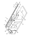
図1〜図4には、本発明による物品搬送装置の第1の実施の形態が示されていて、図1は物品搬送装置の全体を示す斜視図、図2は図1の振動付与機構の部分断面図、図3は図2のA−A線断面図、図4は図2のB−B線断面図である。
Hereinafter, embodiments of the present invention will be described with reference to the drawings.
1 to 4 show a first embodiment of an article conveying apparatus according to the present invention. FIG. 1 is a perspective view showing the entire article conveying apparatus, and FIG. 2 is a diagram of the vibration applying mechanism of FIG. 3 is a partial cross-sectional view, FIG. 3 is a cross-sectional view taken along line AA in FIG. 2, and FIG. 4 is a cross-sectional view taken along line BB in FIG.
すなわち、この物品搬送装置1は、所謂リニア型フィーダであって、物品75を搬送する搬送路4を有する搬送部2と、搬送部2に物品75を搬送するための振動を与える振動付与機構30と、搬送部2に連設される貯蔵機構20とを備えている。
That is, the
搬送部2は、図1に示すように、長尺の略直方体状をなすものであって、上面側に断面I形状の直線状の溝3が全長に亘って設けられ、この溝3が物品75を搬送するための搬送路4に形成されている。搬送路4の底面は、側壁6、7によって直線状に搬送方向が規制された平坦面の搬送面5に形成され、この搬送面5上を物品75が一方向に搬送される。搬送部2は、搬送面5が水平方向を向くように、後述する振動付与機構30の出力部60の上部に取り付けられる。
As shown in FIG. 1, the
搬送部2の搬送方向の中間部には、図1に示すように、側壁7(図中、手前側の側壁7)の内外面間を貫通する排出口8が設けられ、この排出口8を介して後述する姿勢判別部10で搬送路4内から排除された正規な姿勢以外の物品75(異常な姿勢の物品75)が後述する貯蔵機構20に回収される。搬送部2の搬送方向の上流側には、側壁7(図中、手前側の側壁7)の内外面間を貫通する供給口9が設けられ、この供給口9を介して後述する貯蔵機構20に回収された物品75が搬送路4内に戻される。
As shown in FIG. 1, a
物品75は、円柱状の大径部76と、大径部76の一方の端面の中心部に一体に設けられる大径部76よりも小径の円柱状の小径部77とからなる2段円柱状をなすものであって、大径部76が下側に位置する状態を正規な姿勢(正常な姿勢)として搬送路4内を搬送され、それ以外の姿勢のものは後述する姿勢判別部10で搬送路4内から排除される。
The
搬送路4の搬送方向の途中には姿勢判別部10が設けられ、この姿勢判別部10によって搬送路4内を搬送される物品75の姿勢が判別され、正常な姿勢の物品75は姿勢判別部10を通過して次工程に供給され、異常な姿勢の物品75は姿勢判別部10で搬送路4内から排除されて、後述する貯蔵機構20に回収される。
An
姿勢判別部10は、搬送路4の搬送方向の中間部の側壁6(図中、奥側の側壁6)の上部に取り付けられる姿勢判別板11と、姿勢判別板11に対応する搬送路4の側壁7(図中、手前側の側壁7)に沿う底面の部分に設けられる搬送面5よりも一段低い段部13と、段部13に臨む搬送面5の部分(図中、奥側の側壁6に沿う部分)に設けられる小幅部14とから構成されている。
The
姿勢判別板11は、略長方形板状をなすものであって、搬送路4に面する側面12が側壁6(図中、奥側の側壁6)の内面よりも搬送路4内に所定の長さ突出するように、側壁6(図中、奥側の側壁6)の上部にボルト15によって固定され、この突出している側面12の部分に搬送路4内を搬送される物品75の周面の一部が接触するように構成されている。この場合、側面12の長手方向の両端部は面取りされてアール面に形成され、搬送路4内を搬送される物品75の搬送を阻害するのを防止している。
The
段部13は、側壁7(図中、手前側の側壁7)に隣接する搬送路4の底面の部分を略半長円形状に切欠し、その部分を搬送面5よりも一段低く形成したものであって、この段部13によって段部13に臨む搬送面5の部分(奥側の側壁6に沿う部分)が他の部分よりも幅の狭い小幅部14に形成されている。
The
搬送路4内を搬送される物品75のうち、正常な姿勢の物品75(大径部76が下側に位置する物品75)は、大径部76の厚み方向の両端面が姿勢判別板11の下面と搬送面5の小幅部14との間で案内され、小径部77の周面が姿勢判別板11の側面12に接触しながら姿勢判別部10を通過し、搬送部2に連続する次工程に供給される。
Of the
一方、搬送路4内を搬送される物品75のうち、異常な姿勢の物品75(例えば、小径部77が下側に位置する物品75)は、大径部76の厚み方向の両端面が姿勢判別板11と搬送面5の小幅部14との間で案内されることなく、大径部76の周面が姿勢判別板11の側面12に接触することにより、バランスを崩して搬送面5の小幅部14から段部13内に落下し、段部13から段部13に連通している排出口8を介して貯蔵機構20に回収される。
On the other hand, among the
なお、上記の姿勢判別部10は、大径部76と小径部77とを有する2段円柱状の物品75に対応させて構成したものであって、その他の形状の物品を搬送対象物とする場合には、その物品の形状に応じて姿勢判別部10を構成すればよい。
In addition, said attitude | position discrimination |
貯蔵機構20は、図1に示すように、搬送部2に連設されるものであって、搬送部2の搬送路4内に供給する物品75を所定量貯蔵する機能と、搬送部2の搬送路4内から排除された物品75を回収し、搬送路4の上流側に戻す循環機能とを有する搬送手段21を備えている。
As shown in FIG. 1, the
搬送手段21は、搬送部2に隣接する部分に搬送部2に平行かつ水平に設けられ、搬送部2の排出口8と供給口9との間を循環可能なベルト22を有するコンベア23と、コンベア23を回転駆動させる駆動源24と、コンベア23を支持する支持板25とから構成され、支持板25は後述する振動付与機構30と共通の基台72の上部に固定されている。コンベア23は、ベルト22の上面が搬送部2の排出口8の底面及び供給口9の底面よりも僅かに低くなるように、高さが調整されている。
The conveying means 21 is provided in a portion adjacent to the conveying
支持板25の上端には、コンベア23のベルト22の上面との間に所定の間隙が形成されるように、長方形板状のカバー26が一体に設けられている。カバー26の搬送部2に沿う部分には、略長方形状の切欠部27が設けられ、この切欠部27と搬送部2の側壁7(図中、手前側の側壁7)とベルト22の上面とによって囲まれる部分に、上方が開口する略長方形状の貯蔵部28が形成され、この貯蔵部28の長手方向の一端が搬送部2の排出口8に連通し、他端が供給口9に連通している。
A rectangular plate-
貯蔵部28は、ベルト22の上面に所定量の物品75を貯蔵する機能と、搬送路4から排除された物品75を回収し、ベルト22の回転によって搬送路4と反対方向に搬送して、搬送路4の上流側に戻す循環機能とを備えている。
The
なお、搬送手段21は、コンベア23に限らず、他の周知のものを使用してもよい。要は、搬送路4から排除された物品75を回収し、搬送路4の上流側に戻す機能と、所定量の物品75を貯蔵する機能とを備えたものであればよい。
In addition, the conveying
振動付与機構30は、図1〜図4に示すように、搬送部2に物品75を搬送するための振動を与えるものであって、基台72の上部に固定されるハウジング31と、ハウジング31内に回転可能に設けられる入力軸40と、ハウジング31内に設けられるとともに、入力軸40の回転運動を往復直線運動に変換する第1カム機構41と、入力軸40の回転運動を往復直線運動に変換する第2カム機構50と、第1カム機構41及び第2カム機構50によって駆動される出力部60と、入力軸40を回転駆動させる駆動源66とを備えている。
As shown in FIGS. 1 to 4, the
ここで、第1カム機構41は、入力軸40の回転運動を少なくとも物品75の搬送方向を有する第1方向への往復直線運動に変換する機能を有し、第2カム機構50は、入力軸40の回転運動を少なくとも物品75を搬送する搬送面5の法線方向成分を有する第2方向の往復直線運動に変換する機能を有し、これらの2方向への往復直線運動を合成することによって得られる振動が出力部60を介して搬送部2に与えられる。この振動は、搬送面5に対する物品75の相対滑りを有効に制御するために必要な慣性力項に係る搬送方向成分と摩擦力項に係る法線方向成分とを有することになるので、搬送面5上の物品75を搬送方向に効率良く搬送することができる。
Here, the
なお、以下の説明においては、第1方向を水平方向(搬送方向)とし、第2方向を搬送面の法線方向(鉛直方向)とするが、必ずしもこの方向に制限されるものではなく、第1方向への往復直線運動が搬送方向以外の方向の成分を含んでいてもよく、第2方向への往復直線運動が法線方向以外の成分を含んでいてもよい。また、第1方向の搬送方向を水平から所定角度傾斜させ、第2方向をその傾斜させた搬送面の法線方向としてもよい。 In the following description, the first direction is the horizontal direction (transport direction), and the second direction is the normal direction of the transport surface (vertical direction). However, the first direction is not necessarily limited to this direction. The reciprocating linear motion in one direction may include a component in a direction other than the transport direction, and the reciprocating linear motion in the second direction may include a component other than the normal direction. Alternatively, the transport direction in the first direction may be inclined by a predetermined angle from the horizontal, and the second direction may be the normal direction of the transport surface inclined.
ハウジング31は、図2に示すように、内部に空所を有する箱形状をなすものであって、上面側に空所内外を貫通する長方形状の開口部32が設けられている。ハウジング31の空所内には、中央部に単一の入力軸40が水平かつ回転可能に設けられ、入力軸40の上方の開口部32の内側の部分に、出力部60が水平方向(物品75の搬送方向)及び鉛直方向に往復運動可能に設けられ、出力部60と入力軸40との間に第1カム機構41と第2カム機構50とが設けられている。
As shown in FIG. 2, the
入力軸40は、図2に示すように、ハウジング31の対向する前後壁33、34間に一対の軸受35、35を介して回転可能に支持されるとともに、一端部が後壁34を貫通してハウジング31外に突出し、その突出している部分にハウジング31の後壁34の外面側に設けられている駆動源66の駆動軸67が軸継手68を介して連結され、駆動源66の駆動により駆動軸67を介して入力軸40が回転駆動するように構成されている。
As shown in FIG. 2, the
出力部60は、図1、図2及び図4に示すように、ハウジング31の開口部32の内側の部分に水平に設けられる、ハウジング31の開口部32よりも僅かに小さい長方形板状の出力部本体61と、出力部本体61の下面側の長手方向の両端部に一体に設けられる一対の長方形板状のリフト部材62、62とから構成され、出力部本体61の上面側に搬送部2がボルト15によって水平に固定されている。
As shown in FIGS. 1, 2, and 4, the
出力部本体61の周面とハウジング31の開口部32内周面との間には、全周に亘ってゴム等の弾性体からなるシール部材69が介装され、このシール部材69によってハウジング31の空所内に充填される潤滑油70がハウジング31外に漏出するのを防止している。シール部材69は、出力部本体61の水平方向及び鉛直方向への往復直線運動に追従して弾性変形することにより、出力部本体61の水平方向及び鉛直方向への往復直線運動を許容している。
A
一対のリフト部材62、62は、出力部本体61の上面(又は下面)と直交するように、出力部本体61の下面側に一体に設けられるとともに、各リフト部材62の両側面63、63(物品75の搬送方向に沿う端面)は鉛直方向を向く平坦面に形成されている。
The pair of
各リフト部材62の各側面63に対向するハウジング31の内面側の部分には、図2〜図4に示すように、各リフト部材62の各側面63と互いに平行に、かつ各側面63と互いに摺動可能な平坦面の案内面37を有する板状の案内部材36がそれぞれ一体に設けられている。両案内部材36、36によって両リフト部材62、62の水平方向の一方向(搬送方向)及び鉛直方向への移動が許容され、水平方向の他方向(搬送方向と直交する方向)への移動が規制される。これにより、両リフト部材62、62と一体の出力部本体61の水平方向の一方向(搬送方向)及び鉛直方向への移動が許容され、水平方向の他方向(搬送方向と直交する方向)への移動が規制される。
As shown in FIGS. 2 to 4, the portion on the inner surface side of the
各リフト部材62の各側面63とその各側面63と相互に摺動する各案内部材36の案内面37との間に所定の隙間(図示せず)を設け、その間隙内に粘性流体70を介在させることにより、所謂オイルフィルムダンパとして機能させてもよい。
A predetermined gap (not shown) is provided between each
すなわち、各リフト部材62の各側面63と各案内部材36の案内37面との間に所定の隙間を設け、この隙間内に粘性流体70を介在させ、この状態で各リフト部材62と各案内部材36とを相対移動させることにより、粘性流体70には速度勾配が生じ、リフト部材62と案内部材36との間に相対移動の逆向きの力が作用し、この逆向きの力が相対移動を減衰する制動力として作用することになる。
That is, a predetermined gap is provided between each
この場合、ハウジング31内には、前述したように粘性流体である潤滑油70が充填されているので、各リフト部材62の各側面63と各案内部材36の案内面37との間の隙間内には、常時、潤滑油70が介在することになり、オイルフィルムダンパとして機能させることが可能になる。
In this case, since the
そして、このオイルフィルムダンパにより、搬送部2の撓み変形等に起因する搬送部2自身の有害振動を減衰させることができるので、第1カム機構41及び第2カム機構50の作動により、設計通りの振動を搬送部2に与えることができる。
Since the oil film damper can attenuate harmful vibrations of the
なお、リフト部材62と案内部材36との間の隙間は、0.005mm〜0.05mmの範囲に設定するのが好ましい。この範囲内に隙間を設定することにより、案内部材36の案内面37とリフト部材62の側面63との物理的な接触を確実に阻止することができるとともに、搬送部2のガタを小さく抑えることができる。
In addition, it is preferable to set the clearance gap between the
また、案内部材36の案内面37又はリフト部材62の側面63の少なくとも何れか一方に溝を形成してもよい。このような溝を形成することにより、隙間内への粘性流体70の保持力を高めることができるので、オイルフィルムダンパとしての機能が確実に得られる。なお、溝の形状は、特に限定されるものではなく、粘性流体70の保持力を高めるものであればよい。
Further, a groove may be formed on at least one of the
各リフト部材62の下端中央部には、後述する第2カム機構50の第2接触子55がそれぞれ取り付けられ、この第2接触子55と後述する第2カム51との協働により、入力軸40の回転運動が鉛直方向への直線運動に変換されて両リフト部材62、62に伝達され、両リフト部材62、62を介して出力部本体61が鉛直方向に往復直線運動することになる。
A
第1カム機構41は、図2に示すように、入力軸40の中央部に一体に設けられて、入力軸40と一体に回転駆動する第1カム42と、第1カム42と相互に係合する一対の第1接触子46、46とから構成され、この第1カム42と一対の接触子46、46との協働により、入力軸40の回転運動が水平方向の一方向(物品75の搬送方向)への直線運動に変換されて出力部60に伝達され、出力部60が水平方向の一方向(物品75の搬送方向)へ往復直線運動することになる。
As shown in FIG. 2, the
第1カム42は、周面にリブ43が環状に形成される円板状のリブカムであって、リブ43の一方の側面が全周に亘る第1カム面44に形成され、他方の側面が全周に亘る第2カム面45に形成され、第1カム面44及び第2カム面45にそれぞれ第1接触子46が係合している。
The
第1カム42の第1カム面44及び第2カム面45は、それぞれ入力軸40の軸線方向に湾曲(変位)し、かつ入力軸40の外周面から垂直に立ち上がる同一の曲面に形成され、この曲面によって第1カム42のカム曲線が構成される。
The
第1接触子46は、カムフォロア46であって、第1カム42のリブ43の第1カム面44及び第2カム面45に対応する出力部60の出力部本体61の部分にそれぞれ設けられている。各第1接触子46は、出力部本体61の下面側の部分に、嵌合、ねじ止め等の手段によって軸線が鉛直方向を向くように取り付けられる支持軸47と、支持軸47によって水平方向に回転可能に支持されるローラ48とから構成され、各ローラ48の周面が第1カム面44及び第2カム面45に接触している。
The
この場合、一方のカムフォロア46のローラ48の周面が第1カム面44に転動可能に接触し、他方のカムフォロア46のローラ48の周面が第2カム面45に転動可能に接触するように、両カムフォロア46、46の水平方向の間隔が調整されている。
In this case, the peripheral surface of the
両カムフォロア46、46は、それらの間の間隔の調整が可能に構成されており、両カムフォロア46、46間の間隔を調整することにより、各カムフォロア46のローラ48と第1カム面44及び第2カム面45との接触圧を所定の値に調整することができ、バックラッシュを発生させることのない与圧状態を作り出すことができる。
The two
駆動源66を駆動させて入力軸40を回転駆動させることにより、入力軸40と一体に第1カム42が回転駆動し、第1カム42の第1カム面44上及び第2カム面45上をそれぞれ各カムフォロア46のローラ48が接触状態を維持しつつ転動し、両カムフォロア46、46が第1カム面44及び第2カム面45の曲面の形状に応じて水平方向の一方向(搬送方向)に変位し、出力部60の出力部本体61が両カムフォロア46、46と一体に同一方向に変位し、出力部本体61の上部に取り付けられている搬送部2が出力部60と一体に水平方向の一方向(搬送方向)に往復直線運動する。
By driving the
この場合、第1カム42の第1カム面44及び第2カム面45は、入力軸40の外周面から垂直に立ち上がる曲面に形成されるとともに、第1カム面44及び第2カム面45に接触する各カムフォロア46は、支持軸47の軸線が鉛直方向を向き、ローラ48が支持軸47の軸線を中心として水平方向に回転するように構成されているので、後述する第2カム機構50の駆動時に、図5(a)に二点鎖線で示すように、両カムフォロア46、46は出力部60と一体に鉛直方向に移動することになるので、両カムフォロア46、46が出力部60の鉛直方向への往復直線運動を阻害するようなことはなく、出力部60を円滑に鉛直方向に往復直線運動させることができる。
In this case, the
第2カム機構50は、図2〜図4に示すように、入力軸40の第1カム42の両側の部分にそれぞれ一体に設けられて、入力軸40と一体に回転駆動する一対の第2カム51、51と、両第2カム51、51と相互に係合する一対の第2接触子55、55とから構成され、この一対の第2カム51、51と一対の第2接触子55、55との協働により、入力軸40の回転運動が鉛直方向の往復直線運動に変換されて出力部60に伝達され、出力部60が鉛直方向へ往復直線運動することになる。
As shown in FIGS. 2 to 4, the
各第2カム51は、円板状の溝カムであって、一方の側面に入力軸40の軸線を中心として所定の幅、深さの溝52が環状に設けられ、この溝52の内側面及び外側面がそれぞれ第1カム面53及び第2カム面54に形成されている。
Each of the
第1カム面53及び第2カム面54は、入力軸40の軸線と直交する方向に湾曲し、かつ入力軸40の軸線と平行な曲面に形成され、この第1カム面53及び第2カム面54を有する溝52内に第2接触子55のローラ57が転動可能に係合している。第1カム面53及び第2カム面54は、全周に亘って互いに平行な曲面に形成され、この曲面によって第2カム51のカム曲線が構成される。
The
第2接触子55は、第1接触子46と同様にカムフォロア55であって、出力部60の各シフト部材62の下端中央部にそれぞれ取り付けられている。各第2接触子55は、各シフト部材62の下端中央部に嵌合、ねじ止め等の手段によって水平に、かつ入力軸40の軸線と平行に取り付けられる支持軸56と、支持軸56によって鉛直方向に回転可能に支持されるローラ57とからなり、各ローラ57が各第2カム51の溝52内に係合され、各ローラ57の周面が第1カム面53及び第2カム面54にそれぞれ転動可能に接触している。
Similar to the
駆動源66を作動させて入力軸40を回転駆動させることにより、入力軸40と一体に両第2カム51、51が回転駆動し、各第2カム51の溝52内に係合されている各第2接触子55のローラ57の周面が第1カム面53及び第2カム面54上を転動し、両第2接触子55、55が両第2カム51、51の第1カム面53及び第2カム面54の曲面の形状に応じて鉛直方向に変位し、両第2接触子55、55と一体に両リフト部材62、62を介して出力部本体61が同一方向に変位し、出力部本体61の上部に取り付けられている搬送部2が出力部60と一体に鉛直方向に往復直線運動することになる。
By operating the
この場合、各第2カム51の第1カム面53及び第2カム面54は、入力軸40の軸線と平行な曲面に形成されるとともに、各第2カム51の溝52内に係合される各カムフォロア55は、支持軸56の軸線が入力軸40の軸線と平行に、かつローラ57が鉛直方向に回転可能に取り付けられているので、第1カム機構41によって出力部60を水平方向に往復直線運動させる際に、図5(b)に二点鎖線で示すように、両カムフォロア55、55は出力部と一体に水平方向に変位することになるので、両カムフォロア55、55が出力部60の水平方向への往復直線運動を阻害するようなことはなく、出力部60を円滑に水平方向へ往復直線運動させることができる。
なお、図示はしないが、第2カムを周面にカム面が形成される板カムによって構成してもよい。
In this case, the
Although not shown, the second cam may be constituted by a plate cam having a cam surface formed on the peripheral surface.
次に、上記のように構成した本実施の形態による物品搬送装置1の運動軌跡の一例について、図6を参照しながら説明する。
図6の上段には、搬送方向の往復直線運動である水平動のタイミングチャートを示し、下段には、鉛直方向の往復直線運動である上下動のタイミングチャートを示している。上段のタイミングチャートには、左から順に、水平動変位と時間との関係、水平動速度と時間との関係、水平動加速度と時間との関係をそれぞれ示し、下段のタイミングチャートには、左から順に、上下動変位と時間との関係、上下動速度と時間との関係、上下動加速度と時間との関係をそれぞれ示している。なお、上段の3つの図と下段の3つの図の時間軸は、上下の図それぞれにおいて一致している。
Next, an example of the movement trajectory of the
The upper part of FIG. 6 shows a timing chart of horizontal movement that is a reciprocating linear movement in the transport direction, and the lower part shows a timing chart of vertical movement that is a reciprocating linear movement in the vertical direction. The top timing chart shows the relationship between horizontal motion displacement and time, the relationship between horizontal motion speed and time, and the relationship between horizontal motion acceleration and time, respectively, from the left. The bottom timing chart shows the relationship from the left. The relationship between the vertical motion displacement and time, the relationship between the vertical motion speed and time, and the relationship between the vertical motion acceleration and time are respectively shown in order. The time axes of the upper three diagrams and the lower three diagrams are the same in the upper and lower diagrams.
入力軸40が回転駆動して、入力軸40と一体に第1カム42及び第2カム51、51が回転駆動すると、出力部60と一体に搬送部2が水平動及び上下動を行い、これにより、物品75の搬送動作が行われる。
When the
まず、搬送部2の水平動について説明する。
図6に示すように、搬送部2は、第1位置X1から搬送方向の前方へ移動して第2位置X2に至り、第2位置X2から搬送方向の後方へ移動して第1位置X1へ至るよう往復直線移動を行う。すなわち、水平方向において、第1位置X1と第2位置X2との間で前後の水平動を行う。
First, the horizontal movement of the
As shown in FIG. 6, the
この際、搬送部2が第1位置X1から第2位置X2へと前方に移動するのに要する時間は、搬送部2が第2位置X2から第1位置X1へと後方へ移動するのに要する時間よりも長く設定されている。従って、物品75を積極的に搬送することが可能となる。
At this time, the time required for the
すなわち、搬送部2が前方へ移動する時間を長くすることにより、前方への加速度を抑制することができるため、搬送面5上の物品75は搬送面5に対して相対滑りを生じ難く、逆に、搬送部2が後方へ移動する際には急激な移動を行うため、加速度が大きくなって、搬送面5上の物品75は搬送面5に対して相対滑りを生じ易くなる。
That is, by increasing the time during which the
また、搬送部2の水平動において、第1位置X1から前方への移動を開始してから第2位置X2に至るまでの間において、搬送部2は、所定の時間、等速移動を行う。搬送部2が等速移動を行っている間は、搬送面5に載置されている物品75には、搬送部2の加速度に起因する慣性力が作用しないので、搬送面5に対して物品75は滑らない。従って、少なくとも等速移動をしている間は、物品75の相対滑りを有効に抑制することができる。
In addition, in the horizontal movement of the
上記のように構成した本実施の形態による物品搬送装置1にあっては、物品75の搬送を行う搬送部2に貯蔵機構20を連設し、この貯蔵機構20に搬送部2に供給する物品75を貯蔵する貯蔵機能と、搬送部2から排除された物品75を回収し、搬送路2内に戻す循環機能とを付加しているので、搬送効率を大幅に高めることができる。
In the
また、搬送部2の中間部に姿勢判別部10を設けて、異常な姿勢の物品75を搬送部2の搬送路4内から排除し、正常な姿勢の物品75のみを姿勢判別部10を通過させて、搬送部2に連続する次工程へ供給しているので、異常な姿勢の物品75が次工程へ供給されることはなく、不良品の発生を低減させることができるとともに、異常な姿勢の物品75によってラインが停止するのを防止できる。
In addition, the
さらに、搬送路4から排除された物品75を回収して、搬送路4の上流側に戻す搬送手段21にコンベア23を使用しているので、物品75を搬送路4の上流側に戻す動作に振動を伴うようなことはなく、搬送部2の振動と搬送手段21の振動とが干渉するようなことはなく、搬送部2による物品75の搬送に影響を与えることはない。また、振動を伴わないため、静かな運転が可能となる。
Further, since the
さらに、第1カム機構41と第2カム機構50との協働により、搬送面5に振動を付加しているので、材料、判別方法等の条件に応じて適正な振動を搬送面5に与えることができ、形状に特徴の少ない難整列部品のような物品であっても、搬送することが可能となる。
Further, since the vibration is applied to the
さらに、出力部60、すなわち搬送部2をリフト部材62の両側面63、63とハウジング31内面の案内部材36の案内面37との協働により、水平方向の一方向及び鉛直方向のみに往復直線運動可能に案内しているので、常に、搬送面5の全体に渡って安定した一様な搬送を行うことができ、貯蔵機構20との間でのスムーズな物品75の受け渡しが可能になる。
Further, the
さらに、比較的大型の部品の搬送等の搬送面5の水平方向の振幅が大きく必要な場合においても、物品のばたつきの少ない安定した搬送が行うことができ、そのような物品であっても整列した状態で次工程に供給することが可能になる。
Furthermore, even when the horizontal amplitude of the
さらに、搬送部2に貯蔵機構20を連設するだけの簡単な構造なので、全体の構成を簡素化することができ、物品供給ラインを構成する場合に、全体をコンパクト化することができるので、設置スペースを小さくすることができ、省スペース化を図ることができる。
Furthermore, since it is a simple structure that simply connects the
さらに、搬送面5の振動は、独立した第1カム機構41と第2カム機構50とによって水平方向及び鉛直方向への往復直線運動(振動)をそれぞれ作り出し、この2つの往復直線運動(振動)を合成することによって得られるものであるので、それらの振動が互いに干渉するようなことはなく、両カム機構41、50によって正確な安定した動作が得られる。
Further, the vibration of the conveying
さらに、2軸系の振動を合成することにより、搬送面5に物品75を搬送するための振動を与えているので、搬送面5に2次元的な任意の軌跡を与えることが可能になり、汎用性を高めることができる。
Furthermore, since the vibration for conveying the
さらに、第1カム機構41及び第2カム機構50は、それぞれ自由に任意のタイミングを定めることができるので、材質、搬送能力等の使用条件に応じて、搬送に最も適した搬送面5の動きを作り出すことができる。
Furthermore, since the
さらに、リフト部材62と案内部材36との協働により、出力部60が確実に2方向に変位するように案内しているので、付加変動や搬送面5のピッチング振動、搬送面5の撓みによる振動等の影響を受けにくく、常に搬送面5の全面に渡って安定した一様な搬送が可能となる。
Further, since the
図7には、本発明による物品搬送装置の第2の実施の形態が示されていて、この物品搬送装置1は、貯蔵機構20の搬送手段21のコンベア23を傾斜させて配置し、搬送部2の排出口8から供給口9に向かって順次上昇するように構成したものであって、その他の構成は前記第1の実施の形態に示すものと同様である。
FIG. 7 shows a second embodiment of the article conveying apparatus according to the present invention. This
そして、この実施の形態に示す物品搬送装置にあっても、前記第1の実施の形態に示すものと同様に、物品75の搬送を行う搬送部2に貯蔵機構20を連設し、この貯蔵機構20に搬送部2に供給する物品75を貯蔵する貯蔵機能と、搬送部2から排除された物品75を回収し、搬送路2内に戻す循環機能とを付加しているので、搬送効率を大幅に高めることができる。
Even in the article transport apparatus shown in this embodiment, the
また、搬送部2の中間部に姿勢判別部10を設けて、異常な姿勢の物品75を搬送部2の搬送路4内から排除し、正常な姿勢の物品75のみを姿勢判別部10を通過させて、搬送部2に連続する次工程へ供給しているので、異常な姿勢の物品75が次工程へ供給されることはなく、不良品の発生を低減させることができるとともに、異常な姿勢の物品75によってラインが停止するのを防止できる。
In addition, the
さらに、搬送路4から排除された物品75を回収して、搬送路4の上流側に戻す搬送手段21にコンベア23を使用しているので、物品75を搬送路4の上流側に戻す動作に振動を伴うようなことはなく、搬送部2の振動と搬送手段21の振動とが干渉するようなことはなく、搬送部2による物品75の搬送に影響を与えることはない。また、振動を伴わないため、静かな運転が可能となる。
Further, since the
さらに、第1カム機構41と第2カム機構50との協働により、搬送面5に振動を付加しているので、材料、判別方法等の条件に応じて適正な振動を搬送面5に与えることができ、形状に特徴の少ない難整列部品のような物品であっても、搬送することが可能となる。
Further, since the vibration is applied to the
さらに、出力部60、すなわち搬送部2をリフト部材62の両側面63、63とハウジング31内面の案内部材36の案内面37との協働により、水平方向の一方向及び鉛直方向のみに往復直線運動可能に案内しているので、常に、搬送面5の全体に渡って安定した一様な搬送を行うことができ、貯蔵機構20との間でのスムーズな物品75の受け渡しが可能になる。
Further, the
さらに、比較的大型の部品の搬送等の搬送面5の水平方向の振幅が大きく必要な場合においても、物品のばたつきの少ない安定した搬送が行うことができ、そのような物品であっても整列した状態で次工程に供給することが可能になる。
Furthermore, even when the horizontal amplitude of the
さらに、搬送部2に貯蔵機構20を連設するだけの簡単な構造なので、全体の構成を簡素化することができ、物品供給ラインを構成する場合に、全体をコンパクト化することができるので、設置スペースを小さくすることができ、省スペース化を図ることができる。
Furthermore, since it is a simple structure that simply connects the
さらに、搬送面5の振動は、独立した第1カム機構41と第2カム機構50とによって水平方向及び鉛直方向への往復直線運動(振動)をそれぞれ作り出し、この2つの往復直線運動(振動)を合成することによって得られるものであるので、それらの振動が互いに干渉するようなことはなく、両カム機構41、50によって正確な安定した動作が得られる。
Further, the vibration of the conveying
さらに、2軸系の振動を合成することにより、搬送面5に物品75を搬送するための振動を与えているので、搬送面5に2次元的な任意の軌跡を与えることが可能になり、汎用性を高めることができる。
Furthermore, since the vibration for conveying the
さらに、第1カム機構41及び第2カム機構50は、それぞれ自由に任意のタイミングを定めることができるので、材質、搬送能力等の使用条件に応じて、搬送に最も適した搬送面5の動きを作り出すことができる。
Furthermore, since the
さらに、リフト部材62と案内部材36との協働により、出力部60が確実に2方向に変位するように案内しているので、付加変動や搬送面5のピッチング振動、搬送面5の撓みによる振動等の影響を受けにくく、常に搬送面5の全面に渡って安定した一様な搬送が可能となる。
Further, since the
さらに、この実施の形態においては、コンベア23を傾斜させて配置しているので、貯蔵部28の容積を第1の実施の形態に示すものよりも大きくすることができ、第1の実施の形態に示すものよりも多くの物品を貯蔵することができる。
Furthermore, in this embodiment, since the
図8には、本発明による物品搬送装置の第3の実施の形態が示されていて、この物品搬送装置1は、搬送部2から姿勢判別部10を除去し、搬送部2の側壁7(図中、手前側の側壁7)の上流側に供給口9のみを設け、貯蔵機構20に搬送路4内へ供給する物品75を貯蔵する貯蔵機能のみを付加したものであって、その他の構成は前記第1の実施の形態に示すものと同様である。なお、この実施の形態においては、物品75に円柱状のものを使用している。
FIG. 8 shows a third embodiment of the article transporting apparatus according to the present invention. This
そして、この実施の形態に示すものにあっても、前記第1の実施の形態に示すものと同様に、物品75の搬送を行う搬送部2に貯蔵機構20を連設し、この貯蔵機構20に搬送部2に供給する物品75を貯蔵する貯蔵機能を付加しているので、搬送効率を大幅に高めることができる。
And even in what is shown in this embodiment, the
また、搬送手段21にコンベア23を使用しているので、物品75を搬送路4の上流側に戻す動作に振動を伴うようなことはなく、搬送部2の振動と搬送手段21の振動とが干渉するようなことはなく、搬送部2による物品75の搬送に影響を与えることはない。また、振動を伴わないため、静かな運転が可能となる。
Further, since the
さらに、第1カム機構41と第2カム機構50との協働により、搬送面5に振動を付加しているので、材料、判別方法等の条件に応じて適正な振動を搬送面5に与えることができ、形状に特徴の少ない難整列部品のような物品であっても、搬送することが可能となる。
Further, since the vibration is applied to the
さらに、出力部60、すなわち搬送部2をリフト部材62の両側面63、63とハウジング31内面の案内部材36の案内面37との協働により、水平方向の一方向及び鉛直方向のみに往復直線運動可能に案内しているので、常に、搬送面5の全体に渡って安定した一様な搬送を行うことができ、貯蔵機構20との間でのスムーズな物品75の受け渡しが可能になる。
Further, the
さらに、比較的大型の部品の搬送等の搬送面5の水平方向の振幅が大きく必要な場合においても、物品のばたつきの少ない安定した搬送が行うことができ、そのような物品であっても整列した状態で次工程に供給することが可能になる。
Furthermore, even when the horizontal amplitude of the
さらに、搬送部2に貯蔵機構20を連設するだけの簡単な構造なので、全体の構成を簡素化することができ、物品供給ラインを構成する場合に、全体をコンパクト化することができるので、設置スペースを小さくすることができ、省スペース化を図ることができる。
Furthermore, since it is a simple structure that simply connects the
さらに、搬送面5の振動は、独立した第1カム機構41と第2カム機構50とによって水平方向及び鉛直方向への往復直線運動(振動)をそれぞれ作り出し、この2つの往復直線運動(振動)を合成することによって得られるものであるので、それらの振動が互いに干渉するようなことはなく、両カム機構41、50によって正確な安定した動作が得られる。
Further, the vibration of the conveying
さらに、2軸系の振動を合成することにより、搬送面5に物品75を搬送するための振動を与えているので、搬送面5に2次元的な任意の軌跡を与えることが可能になり、汎用性を高めることができる。
Furthermore, since the vibration for conveying the
さらに、第1カム機構41及び第2カム機構50は、それぞれ自由に任意のタイミングを定めることができるので、材質、搬送能力等の使用条件に応じて、搬送に最も適した搬送面5の動きを作り出すことができる。
Furthermore, since the
さらに、リフト部材62と案内部材36との協働により、出力部60が確実に2方向に変位するように案内しているので、付加変動や搬送面5のピッチング振動、搬送面5の撓みによる振動等の影響を受けにくく、常に搬送面5の全面に渡って安定した一様な搬送が可能となる。
Further, since the
1 物品搬送装置 2 搬送部 3 溝
4 搬送路 5 搬送面 6 側壁(奥)
7 側壁(手前) 8 排出口 9 供給口
10 姿勢判別部 11 姿勢判別板 12 側面
13 段部 14 小幅部 15 ボルト
20 貯蔵機構 21 搬送手段 22 ベルト
23 コンベア 24、66 駆動源 25 支持板
26 カバー 27 切欠部 28 貯蔵部
30 振動付与機構 31 ハウジング 32 開口部
33 前壁 34 後壁 35 軸受
36 案内部材 37 案内面 40 入力軸
41 第1カム機構 42 第1カム 43 リブ
44、53 第1カム面 45、54 第2カム面
46 第1接触子 47、56 支持軸
48、57 ローラ 50 第2カム機構
51 第2カム 52 溝 55 第2接触子
60 出力部 61 出力部本体 62 リフト部材
63 側面 67 駆動軸 68 軸継手
69 シール部材 70 潤滑油 72 基台
75 物品 76 大径部 77 小径部
DESCRIPTION OF
7 Side wall (front) 8
Claims (15)
駆動源から入力される回転運動を少なくとも前記搬送方向の成分を有する第1方向への往復直線運動に変換して前記搬送部に伝達する第1カム機構、及び前記駆動源から入力される回転運動を少なくとも前記搬送面の法線方向の成分を有する第2方向への往復直線運動に変換して前記搬送部に伝達する第2カム機構を有し、前記両カム機構の協働により前記搬送部に物品を搬送するための振動を与える振動付与機構と、
前記搬送部に連設されるとともに、前記搬送路内に供給する物品を貯蔵するための貯蔵部を有する貯蔵機構とを備えていることを特徴とする物品搬送装置。 A transport section having a transport surface in which the transport direction is linearly regulated, and transporting an article positioned in the transport path along the transport surface;
A first cam mechanism that converts a rotational motion input from a drive source into a reciprocating linear motion in a first direction having at least a component in the transport direction and transmits it to the transport unit, and a rotational motion input from the drive source Having a second cam mechanism that converts at least a reciprocating linear motion in a second direction having a component in the normal direction of the transport surface and transmits the reciprocating motion to the transport section, and the transport section is cooperated by the two cam mechanisms. A vibration imparting mechanism for imparting vibration to convey the article to
An article transporting apparatus comprising: a storage mechanism that is connected to the transporting unit and has a storage unit for storing articles to be supplied into the transporting path.
前記第2カム機構は、前記入力軸に設けられて入力軸と一体に回転駆動する第2カムと、前記出力部に設けられて出力部と一体に変位するとともに、前記第2カムのカム面と接触する第2接触子とからなり、
前記第1カムと前記第1接触子との協働により、前記入力軸の回転運動が前記第1方向の往復直線運動に変換されて前記出力部に伝達され、前記第2カムと前記第2接触子との協働により、前記入力軸の回転運動が前記第2方向の往復直線運動に変換されて前記出力部に伝達されることを特徴とする請求項6に記載の物品搬送装置。 The first cam mechanism is provided on the input shaft and rotationally driven integrally with the input shaft. The first cam mechanism is provided on the output portion and is displaced integrally with the output portion, and the cam surface of the first cam. A first contactor that comes into contact with
The second cam mechanism is provided on the input shaft and rotationally driven integrally with the input shaft. The second cam mechanism is provided on the output portion and is displaced integrally with the output portion, and the cam surface of the second cam. A second contactor in contact with
By the cooperation of the first cam and the first contact, the rotational movement of the input shaft is converted into the reciprocating linear movement in the first direction and transmitted to the output unit, and the second cam and the second The article conveying apparatus according to claim 6, wherein the rotary motion of the input shaft is converted into a reciprocating linear motion in the second direction and transmitted to the output unit in cooperation with the contact.
前記第1カムは、両側面が前記入力軸の軸線方向に変位し、かつ前記入力軸の外周面から垂直に立ち上がる曲面のカム面に形成され、
前記第1接触子は、前記第1カムの両カム面に転動可能に接触する一対のカムフォロアであることを特徴とする請求項8に記載の物品搬送装置。 The input shaft is supported by the housing such that the axis thereof faces the transport direction,
The first cam is formed on a curved cam surface whose both side surfaces are displaced in the axial direction of the input shaft and rises perpendicularly from the outer peripheral surface of the input shaft,
9. The article conveying apparatus according to claim 8, wherein the first contact is a pair of cam followers that are slidably in contact with both cam surfaces of the first cam.
前記第2接触子は、前記第2カムの環状の溝内に嵌合されて、前記カム面に転動可能に接触するカムフォロアであることを特徴とする請求項9に記載の物品搬送装置。 The second cam has an annular groove on one side surface with the axis of the input shaft as a center, the inner and outer surfaces of the groove are displaced in a direction perpendicular to the axis of the input shaft, and the axis of the input shaft Formed on parallel cam surfaces,
The article conveying apparatus according to claim 9, wherein the second contact is a cam follower that is fitted in an annular groove of the second cam so as to be able to roll on the cam surface.
前記第2接触子は、前記第2カムのカム面に転動可能に接触するカムフォロアであることを特徴とする請求項9に記載の物品搬送装置。 The second cam is formed on a cam surface whose outer peripheral surface is displaced in a direction perpendicular to the axis of the input shaft and parallel to the axis of the input shaft,
The article conveying apparatus according to claim 9, wherein the second contact element is a cam follower that comes into contact with a cam surface of the second cam so as to allow rolling.
前記第2方向の往復直線運動は、前記法線方向の成分のみを有するとともに、該法線方向は鉛直方向であることを特徴とする請求項1から13の何れかに記載の物品搬送装置。 The reciprocating linear motion in the first direction has only a component in the transport direction, and the transport direction is a horizontal direction,
14. The article transporting apparatus according to claim 1, wherein the reciprocating linear motion in the second direction has only the component in the normal direction, and the normal direction is a vertical direction.
前記第2カムは、前記出力部が水平方向に往復直線運動する際に、前記第2接触子との接触状態を維持しつつ接触位置が前記出力部の移動方向と同一方向に移動するカム面を有していることを特徴とする請求項7から14の何れかに記載の物品搬送装置。
The first cam has a cam surface whose contact position moves in the same direction as the movement direction of the output unit while maintaining a contact state with the first contact when the output unit reciprocates linearly in the vertical direction. Have
The second cam has a cam surface on which the contact position moves in the same direction as the movement direction of the output unit while maintaining a contact state with the second contact when the output unit reciprocates linearly in the horizontal direction. The article carrying apparatus according to claim 7, wherein the article carrying apparatus is provided.
Priority Applications (1)
| Application Number | Priority Date | Filing Date | Title |
|---|---|---|---|
| JP2005011986A JP4576246B2 (en) | 2005-01-19 | 2005-01-19 | Article conveying device |
Applications Claiming Priority (1)
| Application Number | Priority Date | Filing Date | Title |
|---|---|---|---|
| JP2005011986A JP4576246B2 (en) | 2005-01-19 | 2005-01-19 | Article conveying device |
Publications (2)
| Publication Number | Publication Date |
|---|---|
| JP2006199416A true JP2006199416A (en) | 2006-08-03 |
| JP4576246B2 JP4576246B2 (en) | 2010-11-04 |
Family
ID=36957758
Family Applications (1)
| Application Number | Title | Priority Date | Filing Date |
|---|---|---|---|
| JP2005011986A Active JP4576246B2 (en) | 2005-01-19 | 2005-01-19 | Article conveying device |
Country Status (1)
| Country | Link |
|---|---|
| JP (1) | JP4576246B2 (en) |
Cited By (1)
| Publication number | Priority date | Publication date | Assignee | Title |
|---|---|---|---|---|
| JP2008087946A (en) * | 2006-10-04 | 2008-04-17 | Sankyo Mfg Co Ltd | Article carrying device |
Citations (7)
| Publication number | Priority date | Publication date | Assignee | Title |
|---|---|---|---|---|
| JPS6448712A (en) * | 1987-08-17 | 1989-02-23 | Mitsubishi Electric Corp | Transport device |
| JPH03102503U (en) * | 1990-02-08 | 1991-10-24 | ||
| JPH04130219U (en) * | 1991-03-11 | 1992-11-30 | ダイキン工業株式会社 | parts supply device |
| JPH05171949A (en) * | 1991-12-25 | 1993-07-09 | Tochigi Fuji Ind Co Ltd | Super charger |
| JPH0999361A (en) * | 1995-10-04 | 1997-04-15 | Shinko Electric Co Ltd | Shake-out machine |
| JP2003040423A (en) * | 2001-07-23 | 2003-02-13 | Sankyo Mfg Co Ltd | Article conveyer |
| JP2003040424A (en) * | 2001-07-23 | 2003-02-13 | Sankyo Mfg Co Ltd | Article conveyer |
-
2005
- 2005-01-19 JP JP2005011986A patent/JP4576246B2/en active Active
Patent Citations (7)
| Publication number | Priority date | Publication date | Assignee | Title |
|---|---|---|---|---|
| JPS6448712A (en) * | 1987-08-17 | 1989-02-23 | Mitsubishi Electric Corp | Transport device |
| JPH03102503U (en) * | 1990-02-08 | 1991-10-24 | ||
| JPH04130219U (en) * | 1991-03-11 | 1992-11-30 | ダイキン工業株式会社 | parts supply device |
| JPH05171949A (en) * | 1991-12-25 | 1993-07-09 | Tochigi Fuji Ind Co Ltd | Super charger |
| JPH0999361A (en) * | 1995-10-04 | 1997-04-15 | Shinko Electric Co Ltd | Shake-out machine |
| JP2003040423A (en) * | 2001-07-23 | 2003-02-13 | Sankyo Mfg Co Ltd | Article conveyer |
| JP2003040424A (en) * | 2001-07-23 | 2003-02-13 | Sankyo Mfg Co Ltd | Article conveyer |
Cited By (1)
| Publication number | Priority date | Publication date | Assignee | Title |
|---|---|---|---|---|
| JP2008087946A (en) * | 2006-10-04 | 2008-04-17 | Sankyo Mfg Co Ltd | Article carrying device |
Also Published As
| Publication number | Publication date |
|---|---|
| JP4576246B2 (en) | 2010-11-04 |
Similar Documents
| Publication | Publication Date | Title |
|---|---|---|
| US7219792B2 (en) | Article carrying apparatus | |
| KR100651011B1 (en) | Article carrying apparatus | |
| US6708815B2 (en) | Article conveyor device | |
| EP1652797B1 (en) | Article carrying apparatus | |
| KR100460564B1 (en) | Article Transfer Device | |
| JP4576246B2 (en) | Article conveying device | |
| EP1652796B1 (en) | Article carrying apparatus | |
| JP5102993B2 (en) | Article conveying device | |
| JP2008114988A (en) | Article conveyer | |
| JP4576245B2 (en) | Article conveying device | |
| EP1908707A2 (en) | Product transport apparatus | |
| JP4621477B2 (en) | Article conveying device | |
| JP6990798B1 (en) | Vibration type article transfer device and vibration type article transfer method | |
| JP6493021B2 (en) | Transport device | |
| JP2014237509A (en) | Article conveying device | |
| JP2020097998A (en) | Workpiece holding device | |
| JP2018039601A (en) | Component supply device and component supply method | |
| JP2007119171A (en) | Vibrating conveyor | |
| JP2008213963A (en) | Product transport apparatus |
Legal Events
| Date | Code | Title | Description |
|---|---|---|---|
| A621 | Written request for application examination |
Free format text: JAPANESE INTERMEDIATE CODE: A621 Effective date: 20071220 |
|
| A977 | Report on retrieval |
Free format text: JAPANESE INTERMEDIATE CODE: A971007 Effective date: 20100513 |
|
| A131 | Notification of reasons for refusal |
Free format text: JAPANESE INTERMEDIATE CODE: A131 Effective date: 20100518 |
|
| A521 | Request for written amendment filed |
Free format text: JAPANESE INTERMEDIATE CODE: A523 Effective date: 20100707 |
|
| TRDD | Decision of grant or rejection written | ||
| A01 | Written decision to grant a patent or to grant a registration (utility model) |
Free format text: JAPANESE INTERMEDIATE CODE: A01 Effective date: 20100727 |
|
| A01 | Written decision to grant a patent or to grant a registration (utility model) |
Free format text: JAPANESE INTERMEDIATE CODE: A01 |
|
| A61 | First payment of annual fees (during grant procedure) |
Free format text: JAPANESE INTERMEDIATE CODE: A61 Effective date: 20100823 |
|
| R150 | Certificate of patent or registration of utility model |
Free format text: JAPANESE INTERMEDIATE CODE: R150 Ref document number: 4576246 Country of ref document: JP Free format text: JAPANESE INTERMEDIATE CODE: R150 |
|
| FPAY | Renewal fee payment (event date is renewal date of database) |
Free format text: PAYMENT UNTIL: 20130827 Year of fee payment: 3 |
|
| R250 | Receipt of annual fees |
Free format text: JAPANESE INTERMEDIATE CODE: R250 |
|
| R250 | Receipt of annual fees |
Free format text: JAPANESE INTERMEDIATE CODE: R250 |
|
| R250 | Receipt of annual fees |
Free format text: JAPANESE INTERMEDIATE CODE: R250 |
|
| R250 | Receipt of annual fees |
Free format text: JAPANESE INTERMEDIATE CODE: R250 |
|
| R250 | Receipt of annual fees |
Free format text: JAPANESE INTERMEDIATE CODE: R250 |
|
| R250 | Receipt of annual fees |
Free format text: JAPANESE INTERMEDIATE CODE: R250 |
|
| R250 | Receipt of annual fees |
Free format text: JAPANESE INTERMEDIATE CODE: R250 |
|
| R250 | Receipt of annual fees |
Free format text: JAPANESE INTERMEDIATE CODE: R250 |
|
| R250 | Receipt of annual fees |
Free format text: JAPANESE INTERMEDIATE CODE: R250 |
|
| R250 | Receipt of annual fees |
Free format text: JAPANESE INTERMEDIATE CODE: R250 |
|
| R250 | Receipt of annual fees |
Free format text: JAPANESE INTERMEDIATE CODE: R250 |