JP2006197687A - Three-phase rectifying circuit - Google Patents
Three-phase rectifying circuit Download PDFInfo
- Publication number
- JP2006197687A JP2006197687A JP2005004884A JP2005004884A JP2006197687A JP 2006197687 A JP2006197687 A JP 2006197687A JP 2005004884 A JP2005004884 A JP 2005004884A JP 2005004884 A JP2005004884 A JP 2005004884A JP 2006197687 A JP2006197687 A JP 2006197687A
- Authority
- JP
- Japan
- Prior art keywords
- input
- unit
- power supply
- unit power
- voltage
- Prior art date
- Legal status (The legal status is an assumption and is not a legal conclusion. Google has not performed a legal analysis and makes no representation as to the accuracy of the status listed.)
- Pending
Links
Images


Abstract
Description
本発明は、三相交流を入力源とし、入力と絶縁された直流又は交流を出力する3つの単位電源部と、これら単位電源部から出力された電力を負荷に供給する出力部とを備えた三相整流回路に関するものである。 The present invention includes three unit power supply units that use a three-phase alternating current as an input source and output direct current or alternating current that is insulated from the input, and an output unit that supplies the power output from these unit power supply units to a load. The present invention relates to a three-phase rectifier circuit.
従来の三相交流を入力源とし、入力と絶縁された直流又は交流を出力する3つの単位電源部と、これら単位電源部から出力された電力を負荷に供給する出力部とを備えた三相整流回路において、例えば低圧100Vと高圧200Vの入力電圧を取りたい場合、入力源と単位電源部との間にデルタ結線を接続して低圧の入力電圧を取り、入力源と単位電源部との間にスター結線を接続して高圧の入力電圧を取っていた(三相4線式の例として、特許文献1参照)。
しかし、このように構成してある三相整流装置は、入力電圧を、低圧から高圧、若しくは高圧から低圧に切り替えたい場合、結線を変える必要性があることから、切り替えの作業性が悪いという問題点があった。また、デルタ接続からスター接続、若しくはスター接続からデルタ接続に変更することなしに同一の単位電源部を使用する場合、三相整流装置は低圧大電流と高圧小電流の両方で機能する必要があることから、三相整流装置を大型にする必要があったり、効率が下がるなどの問題点があった。 However, the three-phase rectifier configured in this way has a problem that the switching work is poor because it is necessary to change the connection when the input voltage is to be switched from low voltage to high voltage or from high voltage to low voltage. There was a point. If the same unit power supply is used without changing from delta connection to star connection or from star connection to delta connection, the three-phase rectifier must function with both low voltage high current and high voltage small current. For this reason, there is a problem that it is necessary to enlarge the three-phase rectifier and the efficiency is lowered.
本発明は、上記問題に鑑みてなされたものであり、入力電圧を、低圧から高圧、若しくは高圧から低圧にスムースに切り替えることが可能な三相整流装置を提供する。 The present invention has been made in view of the above problems, and provides a three-phase rectifier capable of smoothly switching an input voltage from a low voltage to a high voltage, or from a high voltage to a low voltage.
上記課題を解決するために、本発明に係る三相整流装置は、三相交流を入力源とし、入力と絶縁された直流又は交流を出力する3つの単位電源部と、これら単位電源部から出力された電力を負荷に供給する出力部とを備えた三相整流回路において、前記入力源と単位電源部との間に、入力切換部を設け、この入力切換部は、各相間に切替スイッチを備え、これら切替スイッチの一端をそれぞれ一方の単位電源部の入力に接続し、他端をそれぞれ他方の単位電源部の入力若しくは共通の中性点のいずれかを選択して接続できるように構成してあり、入力電圧に応じて、前記切替スイッチがほぼ同時に、前記他方の単位電源部の入力若しくは前記共通の中性点のいずれかに切り替わり接続するように構成してあることを特徴とする。 In order to solve the above-mentioned problems, a three-phase rectifier according to the present invention has three unit power supply units that output three-phase alternating current as an input source, outputs direct current or alternating current insulated from the input, and outputs from these unit power supply portions. In the three-phase rectifier circuit including an output unit for supplying the generated power to the load, an input switching unit is provided between the input source and the unit power source unit, and the input switching unit includes a switching switch between the phases. One end of each of these changeover switches is connected to the input of one unit power supply unit, and the other end is configured so that either the input of the other unit power supply unit or the common neutral point can be selected and connected. According to the input voltage, the change-over switch is configured to be switched and connected to either the input of the other unit power supply unit or the common neutral point almost simultaneously.
本発明によれば、切換リレースイッチにより、容易に、デルタ接続からスター接続、若しくはスター接続からデルタ接続に変更することができ、三相整流装置を大型にする必要もなく、効率も下げることなく、入力電圧を、低圧から高圧、若しくは高圧から低圧にスムースに切り替えることができる効果がある。 According to the present invention, it is possible to easily change from a delta connection to a star connection or from a star connection to a delta connection by means of a changeover relay switch, without requiring a large three-phase rectifier and reducing efficiency. There is an effect that the input voltage can be smoothly switched from the low voltage to the high voltage, or from the high voltage to the low voltage.
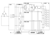
図1及び図3に本発明を実施するための最良の形態における概略回路図を示し、図2及び図4に要部の概略回路図を示す。この三相整流装置は、三相交流を入力源Vinとし、入力と絶縁された直流を出力する3つの単位電源部1,2,3を設けてある。なお、本実施形態では、単位電源部1,2,3をトランスTによって入出力間が絶縁され、直流を出力するように構成してあるが、入出力間が絶縁されていれば、交流を出力するように構成してあってもよい。これについては、以下の実施例においても同様である。本実施形態に係る三相整流装置は、単位電源部1,2,3から出力された電力を負荷に供給する出力部10を備えてあり、単位電源部1,2,3と出力部10とを並列に接続してある。
1 and 3 show schematic circuit diagrams in the best mode for carrying out the present invention, and FIGS. 2 and 4 show schematic circuit diagrams of main parts. This three-phase rectifier is provided with three unit
本実施形態に係る三相整流装置は、入力源Vinと単位電源部1,2,3との間に、入力切換部20を設けてある。この入力切換部20は、三相各相間に切替スイッチ21,22,23を備えてあり、これら切替スイッチ21,22,23の一端をそれぞれ一方の単位電源部1,2,3の入力に接続し、図1に示すように、切替スイッチ21,22,23の他端を共通の中性点24に接続してある。以上のように、切替スイッチ21,22,23の一端をそれぞれ一方の単位電源部1,2,3の入力に接続し、切替スイッチ21,22,23の他端を共通の中性点24に接続することにより、図2に示すようなスター接続になる。通常はスター接続にしてある。
In the three-phase rectifier according to this embodiment, an
また、図3に示すように、切替スイッチ21,22,23の他端をそれぞれ他方の単位電源部2,3,1の入力に接続してある。以上のように、切替スイッチ21,22,23の両端をそれぞれ単位電源部1,2,3の入力に接続することにより、図4に示すようなデルタ接続になる。
Further, as shown in FIG. 3, the other ends of the
本実施形態に係る三相整流装置は入力監視部30を備え、入力監視部30に印加される三相入力電圧を監視・検出し、入力電圧が入力監視部30で設定した値以下になったことを入力監視部30が検出すると、切替スイッチ21,22,23が切り替わり、スター接続からデルタ接続に切り替わるようにしてある。
The three-phase rectifier according to the present embodiment includes an
以上のように構成してある三相整流装置は以下のような作用になる。先ず、三相交流電源Vinが起動すると、通常は高圧の入力電圧の状態で入力電流が入力切替部20に流れる。このとき、本実施形態に係る三相整流装置の入力切替部20は図1及び図2に示すようなスター接続にしてある。
The three-phase rectifier configured as described above operates as follows. First, when the three-phase AC power source Vin is activated, an input current normally flows to the
入力電圧が入力監視部30に印加されると、入力監視部30がこれを監視する。通常状態では、入力切替部20はスター接続された単位電源部1,2,3に電流が流れ、トランスTを介して、出力部10に電流が流れて、負荷に電力を供給する。
When the input voltage is applied to the
三相入力電圧が入力監視部30に印加されると、入力監視部30がこれを監視しているが、入力電圧が入力監視部30で設定した値以下になったことを入力監視部30が検出すると、切替スイッチ21,22,23の他端が共通の中性点24から、他方の単位電源部2,3,1の入力に接続が切り替わり、入力切替部20の接続がスター接続からデルタ接続に切り替わる。これにより、例えば200Vの高圧の入力電圧から100Vの低圧の入力電圧に切り替わる。
When the three-phase input voltage is applied to the
逆に、入力電圧が入力監視部30で設定した値以上になったことを入力監視部30が検出すると、切替スイッチ21,22,23の他端が他方の単位電源部2,3,1の入力から、共通の中性点24に接続が切り替わり、入力切替部20の接続がデルタ接続からスター接続に切り替わる。これにより、例えば100Vの低圧の入力電圧から200Vの高圧の入力電圧に切り替わる。
Conversely, when the
なお、本実施形態においては、高圧の入力電圧から低圧の入力電圧へ、及び、低圧の入力電圧から高圧の入力電圧へ切り替えることができるが、低圧の入力電圧から高圧の入力電圧へ切り替える場合、高圧の入力電圧から低圧の入力電圧へ切り替える場合に比べて、負荷に与える影響が大きいため、この場合は、一度入力を停止して、切替スイッチ21,22,23を切り替えることが最適である。
In this embodiment, it is possible to switch from a high voltage input voltage to a low voltage input voltage, and from a low voltage input voltage to a high voltage input voltage, but when switching from a low voltage input voltage to a high voltage input voltage, Compared with switching from a high input voltage to a low input voltage, the influence on the load is greater. In this case, it is optimal to stop the input once and switch the
以上の作用より、容易に、デルタ接続からスター接続、若しくはスター接続からデルタ接続に変更することができ、三相整流装置を大型にする必要もなく、効率も下げることなく、入力電圧を、低圧から高圧、若しくは高圧から低圧にスムースに切り替えることができる効果がある。 As a result of the above, it is easy to change from delta connection to star connection, or from star connection to delta connection, without the need for a large three-phase rectifier and lowering the input voltage without reducing the efficiency. There is an effect that can be switched smoothly from high pressure to high pressure or from high pressure to low pressure.
図5及び図6には前記実施形態とは異なる実施例を示してある。この実施例に係る三相整流装置は、概ね前記実施形態と同様であり、単位電源部1,2,3と出力部10とを直列に接続してある点のみ異なる。なお、作用については前記実施形態とほぼ同様である。
5 and 6 show an example different from the above embodiment. The three-phase rectifier according to this example is substantially the same as that of the above embodiment, and differs only in that the unit
本発明によれば、切換リレースイッチにより、容易に、デルタ接続からスター接続、若しくはスター接続からデルタ接続に変更することができ、三相整流装置を大型にする必要もなく、効率も下げることなく、入力電圧を、低圧から高圧、若しくは高圧から低圧にスムースに切り替えることができ、産業上利用可能である。 According to the present invention, it is possible to easily change from a delta connection to a star connection or from a star connection to a delta connection by means of a changeover relay switch, without requiring a large three-phase rectifier and reducing efficiency. The input voltage can be switched smoothly from a low voltage to a high voltage, or from a high voltage to a low voltage, which is industrially applicable.
1,2,3 単位電源部
10 出力部
20 入力切替部
21,22,23 切替スイッチ
24 中性点
30 入力監視部
Vin 三相交流入力源
T トランス
1, 2, 3 Unit power supply unit 10
Claims (1)
Priority Applications (1)
| Application Number | Priority Date | Filing Date | Title |
|---|---|---|---|
| JP2005004884A JP2006197687A (en) | 2005-01-12 | 2005-01-12 | Three-phase rectifying circuit |
Applications Claiming Priority (1)
| Application Number | Priority Date | Filing Date | Title |
|---|---|---|---|
| JP2005004884A JP2006197687A (en) | 2005-01-12 | 2005-01-12 | Three-phase rectifying circuit |
Publications (1)
| Publication Number | Publication Date |
|---|---|
| JP2006197687A true JP2006197687A (en) | 2006-07-27 |
Family
ID=36803305
Family Applications (1)
| Application Number | Title | Priority Date | Filing Date |
|---|---|---|---|
| JP2005004884A Pending JP2006197687A (en) | 2005-01-12 | 2005-01-12 | Three-phase rectifying circuit |
Country Status (1)
| Country | Link |
|---|---|
| JP (1) | JP2006197687A (en) |
Cited By (5)
| Publication number | Priority date | Publication date | Assignee | Title |
|---|---|---|---|---|
| JP2009261163A (en) * | 2008-04-18 | 2009-11-05 | Cosel Co Ltd | Three-phase power factor correcting circuit |
| CN104852592A (en) * | 2014-02-18 | 2015-08-19 | 三菱电机株式会社 | Three-phase alternating-current power supply switching circuit |
| JP2022018270A (en) * | 2020-07-15 | 2022-01-27 | 株式会社三社電機製作所 | Parallel operation power supply |
| JP2022034712A (en) * | 2020-08-19 | 2022-03-04 | 株式会社三社電機製作所 | Parallel operation power supply device |
| WO2024017172A1 (en) * | 2022-07-19 | 2024-01-25 | 深圳市海柔创新科技有限公司 | Charging control circuit and electronic device |
Citations (3)
| Publication number | Priority date | Publication date | Assignee | Title |
|---|---|---|---|---|
| JPH10271823A (en) * | 1997-03-21 | 1998-10-09 | Shindengen Electric Mfg Co Ltd | Power factor improved three-phase converter |
| JPH10304663A (en) * | 1997-04-22 | 1998-11-13 | Shindengen Electric Mfg Co Ltd | Three-phase power factor improved converter |
| JPH11275865A (en) * | 1998-03-25 | 1999-10-08 | Shindengen Electric Mfg Co Ltd | Three-phase wide range input power converting circuit |
-
2005
- 2005-01-12 JP JP2005004884A patent/JP2006197687A/en active Pending
Patent Citations (3)
| Publication number | Priority date | Publication date | Assignee | Title |
|---|---|---|---|---|
| JPH10271823A (en) * | 1997-03-21 | 1998-10-09 | Shindengen Electric Mfg Co Ltd | Power factor improved three-phase converter |
| JPH10304663A (en) * | 1997-04-22 | 1998-11-13 | Shindengen Electric Mfg Co Ltd | Three-phase power factor improved converter |
| JPH11275865A (en) * | 1998-03-25 | 1999-10-08 | Shindengen Electric Mfg Co Ltd | Three-phase wide range input power converting circuit |
Cited By (10)
| Publication number | Priority date | Publication date | Assignee | Title |
|---|---|---|---|---|
| JP2009261163A (en) * | 2008-04-18 | 2009-11-05 | Cosel Co Ltd | Three-phase power factor correcting circuit |
| CN104852592A (en) * | 2014-02-18 | 2015-08-19 | 三菱电机株式会社 | Three-phase alternating-current power supply switching circuit |
| EP2908419A1 (en) * | 2014-02-18 | 2015-08-19 | Mitsubishi Electric Corporation | Three-phase alternating-current power supply switching circuit |
| JP2015154660A (en) * | 2014-02-18 | 2015-08-24 | 三菱電機株式会社 | Three-phase ac power supply changeover circuit |
| US9178426B2 (en) | 2014-02-18 | 2015-11-03 | Mitsubishi Electric Corporation | Three-phase alternating-current power supply switching circuit |
| JP2022018270A (en) * | 2020-07-15 | 2022-01-27 | 株式会社三社電機製作所 | Parallel operation power supply |
| JP7075447B2 (en) | 2020-07-15 | 2022-05-25 | 株式会社三社電機製作所 | Parallel operation power supply |
| JP2022034712A (en) * | 2020-08-19 | 2022-03-04 | 株式会社三社電機製作所 | Parallel operation power supply device |
| JP7102473B2 (en) | 2020-08-19 | 2022-07-19 | 株式会社三社電機製作所 | Parallel operation power supply |
| WO2024017172A1 (en) * | 2022-07-19 | 2024-01-25 | 深圳市海柔创新科技有限公司 | Charging control circuit and electronic device |
Similar Documents
| Publication | Publication Date | Title |
|---|---|---|
| KR101828225B1 (en) | Power supply system | |
| JP2010115008A (en) | Uninterruptible power supply apparatus | |
| TW201601419A (en) | Uninterruptible power supply apparatus | |
| WO2014192540A1 (en) | Power conversion device | |
| JP2006197687A (en) | Three-phase rectifying circuit | |
| JP2010158098A (en) | Power supply unit and electronic apparatus | |
| JP2011193584A (en) | Overcurrent protective device | |
| JP2006288032A (en) | Multi-input power supply circuit and its power supply switching method | |
| JP2010115049A (en) | Multi-output switching power supply device | |
| JP2009033943A (en) | Direct high voltage inverter apparatus | |
| JP5611009B2 (en) | Unbalance compensator | |
| JP5293072B2 (en) | AC-AC direct conversion device | |
| JP2008283729A (en) | Uninterruptible power supply unit | |
| JP2009017656A (en) | Power supply system and arc machining power supply system | |
| JP2005269706A (en) | Uninterruptible power supply system | |
| JP2005287129A (en) | Standby type power supply apparatus | |
| JP2007181331A (en) | Inverter system | |
| KR101343953B1 (en) | Double conversion uninterruptible power supply of eliminated battery discharger | |
| JP2008136316A (en) | Charging device and method for power supply unit | |
| JP2009296830A (en) | Uninterruptible power supply device | |
| JP2006271080A (en) | Power supply system and input current balancing control method | |
| JP2011030324A (en) | Electric power unit | |
| JP2005094963A (en) | Pwm cycloconverter | |
| KR200293258Y1 (en) | Single stage high power factor converter | |
| JP2006325353A (en) | Three-phase rectifier instrument |
Legal Events
| Date | Code | Title | Description |
|---|---|---|---|
| A621 | Written request for application examination |
Free format text: JAPANESE INTERMEDIATE CODE: A621 Effective date: 20070525 |
|
| A977 | Report on retrieval |
Free format text: JAPANESE INTERMEDIATE CODE: A971007 Effective date: 20100419 |
|
| A131 | Notification of reasons for refusal |
Free format text: JAPANESE INTERMEDIATE CODE: A131 Effective date: 20100427 |
|
| A02 | Decision of refusal |
Free format text: JAPANESE INTERMEDIATE CODE: A02 Effective date: 20100831 |