JP2006196121A - Optical information recording and reproducing device - Google Patents
Optical information recording and reproducing device Download PDFInfo
- Publication number
- JP2006196121A JP2006196121A JP2005008219A JP2005008219A JP2006196121A JP 2006196121 A JP2006196121 A JP 2006196121A JP 2005008219 A JP2005008219 A JP 2005008219A JP 2005008219 A JP2005008219 A JP 2005008219A JP 2006196121 A JP2006196121 A JP 2006196121A
- Authority
- JP
- Japan
- Prior art keywords
- signal
- push
- spherical aberration
- recording
- lens
- Prior art date
- Legal status (The legal status is an assumption and is not a legal conclusion. Google has not performed a legal analysis and makes no representation as to the accuracy of the status listed.)
- Withdrawn
Links
Images


Abstract
Description
本発明は、光学的情報記録再生装置における、複数の記録再生情報面を持つ光ディスク媒体での、ディファレンシャルプッシュプル法によるトラッキングエラー信号及び対物レンズの位置検出信号を生成する光学的情報記録再生装置に関するものである。 The present invention relates to an optical information recording / reproducing apparatus that generates a tracking error signal and a position detection signal of an objective lens by a differential push-pull method on an optical disc medium having a plurality of recording / reproducing information surfaces. Is.
CD−R、DVD−R等の光記録ディスクのドライブ装置におけるトラッキングサーボ方式の1つとして、ディファレンシャルプッシュプル法(以下、DPP法)が知られている。 A differential push-pull method (hereinafter referred to as DPP method) is known as one of tracking servo methods in a drive device for optical recording disks such as CD-R and DVD-R.
DPP法は、複数のビームを所定間隔でディスクに照射し、そのそれぞれの反射光から得られる検出信号を演算することにより、対物レンズの移動によるオフセットを抑制したトラッキングエラー信号を生成する。 In the DPP method, a disk is irradiated with a plurality of beams at a predetermined interval, and a detection signal obtained from each reflected light is calculated, thereby generating a tracking error signal in which an offset due to movement of the objective lens is suppressed.
又、上記検出信号の演算方法を変えることによって、対物レンズの位置検出信号が生成される。このような技術は、例えば、特許文献1,2等に開示されている。
Further, the position detection signal of the objective lens is generated by changing the calculation method of the detection signal. Such a technique is disclosed in, for example,
以下、DPP法に関して説明する
光源からの光束を、光源と対物レンズ間に配置された波面分割素子により0次光であるメインビーム及び±1次光である2つのサブビームに分け、対物レンズで光ディスクに集光して、メインビーム及び2つのサブビームの光ディスクからの反射光を図8で示すようなフォトディテクターで受光する。0次光のメインビームを受光するメインビーム光検出器100は縦横4つに分割され、±1次光のサブビームを受光するサブビーム光検出器101,102は、縦2つに分割されている。そして、各分割された素子からの出力をA,B,C,D,E,F,G,Hで示すと、これらの各信号を演算することにより、トラッキングエラー信号及びレンズ位置検出信号が生成される。即ち、以下のように生成される。
The DPP method will be described below. A light beam from a light source is divided into a main beam that is zero-order light and two sub-beams that are ± first-order light by a wavefront splitting element disposed between the light source and the objective lens, and the optical disk is used by the objective lens. Then, the reflected light from the optical disk of the main beam and the two sub beams is received by a photodetector as shown in FIG. The
メインビームのプッシュプル信号MPPは、
MPP=(A+D)−(B+C)
により得られ、サブビームのプッシュプル信号の和SPPは、サブビームそれぞれのプッシュプル信号出力を加算して得られる出力として、
SPP=(E−F)+(G−H)
により得られる。そして、DPP信号は、SPPをK0倍した信号とMPPの差動を取り、
DPP=MPP・K0×SPP
により得られる。
The push-pull signal MPP of the main beam is
MPP = (A + D)-(B + C)
The sub-beam push-pull signal sum SPP is obtained as an output obtained by adding the push-pull signal outputs of the sub-beams.
SPP = (E−F) + (G−H)
Is obtained. And the DPP signal takes the differential of MPP and the signal obtained by multiplying SPP by K0,
DPP = MPP · K0 × SPP
Is obtained.
ここで、K0は、メインビームと2つのサブビームの、光強度の差異を補正・校正すように決められる定数であり、例えば、対物レンズの移動に伴なうDCオフセットが発生しないように設定されている。 Here, K0 is a constant determined so as to correct and calibrate the difference in light intensity between the main beam and the two sub beams. For example, K0 is set so that a DC offset due to the movement of the objective lens does not occur. ing.
一方、レンズ位置検出信号LSPは、
LPS=MPP+K0×SPP
により得られる。
On the other hand, the lens position detection signal LSP is
LPS = MPP + K0 × SPP
Is obtained.
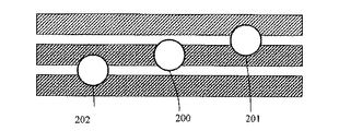
このとき、光ディスク上でのスポットの配置は、回折格子の光軸周りの回転調整等により、図9に示すように、メインビームによるメインスポット200はグルーブ上に、サブビームによるサブスポット201,202は、メインスポットを挟んで対称な位置のランド上になるようなっている(図9においてディスクのグルーブ部にハッチングを施す)。即ち、グルーブ周期を基準としたとき、スポット、サブスポット間間隔は、略グルーブ周期の半分となっている。
At this time, the arrangement of the spots on the optical disc is such that the
この結果、K0を適当な値に設定することにより、DPP信号では、期待される最大値に略等しい振幅となり、且つ、対物レンズ位置移動によるオフセットの発生が抑制される。同時に、LPS信号では、対物レンズ位置移動による各プッシュプル信号で発生するオフセット成分のみが抽出され、対物レンズ位置移動に対応する信号が得られる。 As a result, by setting K0 to an appropriate value, the DPP signal has an amplitude substantially equal to the expected maximum value, and the occurrence of an offset due to the objective lens position movement is suppressed. At the same time, in the LPS signal, only the offset component generated in each push-pull signal due to the objective lens position movement is extracted, and a signal corresponding to the objective lens position movement is obtained.
このLPS信号は、光ヘッドをディスク半径方向へシークさせる際に発生する対物レンズの振動抑制、或は光ヘッドの姿勢により対物レンズが自重により変位することの防止に使用される。 This LPS signal is used to suppress vibration of the objective lens that occurs when the optical head seeks in the radial direction of the disk, or to prevent the objective lens from being displaced by its own weight due to the attitude of the optical head.
又、上記K0の調整は、例えば、特許文献2等に開示されているように、LPS信号に含まれる交流成分(トラッキング変調成分)が最小となるように調整したり、対物レンズを所定量シフトさせて、DPP信号に含まれるDCオフセット成分が最小となるようにしている。
In addition, the adjustment of K0 is performed so that the AC component (tracking modulation component) included in the LPS signal is minimized, or the objective lens is shifted by a predetermined amount as disclosed in, for example,
近年、DVDや、次世代光ディスクである、ブルーレイディスク、HD−DVDディスク等では、2層若しくはそれ以上の情報面を持つ多層ディスクが現れている。このような、多層のディスクは、多数のディスクを張り合わせて作成されたもので、その情報面毎の特性は単層の異なるディスクと同じようにばらつきがある。又、ディスクにチルトがある場合、媒体の厚さに比例してチルトの影響が大きくなるので、ディスク表面から遠い奥の情報面ほどチルトの影響が大きくなることになる。このように、ディスクの特性、チルトの影響によって、メインビーム及びサブビームの品位が劣化するが、その劣化の割合が異なる場合がある。このようなことが起こると、メイン及びサブビームより得られるMPP信号と、SPP信号の対物レンズ移動によるDCオフセットのプッシュプル振幅に対する比率が変わってしまうことがある。 In recent years, multi-layer discs having two or more layers of information have appeared in DVDs and next-generation optical discs such as Blu-ray discs and HD-DVD discs. Such a multi-layer disc is produced by laminating a large number of discs, and the characteristics of each information surface vary in the same manner as discs having different single layers. When the disc has a tilt, the influence of the tilt increases in proportion to the thickness of the medium. Therefore, the influence of the tilt increases as the information surface becomes farther from the disc surface. As described above, the quality of the main beam and the sub beam is deteriorated due to the characteristics of the disc and the tilt, but the deterioration rate may be different. When this occurs, the ratio of the MPP signal obtained from the main and sub beams to the push-pull amplitude of the DC offset due to the movement of the objective lens of the SPP signal may change.
つまり、多層ディスクの場合、その情報面ごとに、特性の違い、チルトの影響によって、DPP信号の対物レンズ位置シフトによるオフセットや、LPS信号のトラッキングエラー成分の混入の割合が変わるということになる。DPP信号の対物レンズ位置によるオフセットの発生は、トラッキング制御の誤差となり、記録時の隣接トラックへの書き込み、再生信号への隣接トラックからのクロストーク増大等を起こし、記録再生信号の劣化要因となる。 That is, in the case of a multi-layer disc, the ratio of the DPP signal due to the objective lens position shift and the mixing ratio of the tracking error component of the LPS signal change due to the difference in characteristics and the influence of tilt for each information surface. The occurrence of offset due to the position of the objective lens of the DPP signal results in tracking control errors, writing to the adjacent track during recording, increasing crosstalk from the adjacent track to the reproduction signal, and the like, causing deterioration of the recording / reproduction signal. .
又、LPS信号へのトラキングエラー成分の混入は、ジーク時等のレンズ位置固定制御への外乱となり、シークを不安定にさせ、アクセス時間の増大、シーク失敗等の要因となる。 In addition, the mixing of tracking error components into the LPS signal causes disturbance to the lens position fixing control at the time of seeking, etc., makes the seek unstable, and causes an increase in access time and seek failure.
本発明の目的は、多層ディスクでのDPP信号の誤差増大を抑え、ディスクの記録再生情報面ごとの自動調整が可能な光学的情報記録再生装置を提供することにある。 An object of the present invention is to provide an optical information recording / reproducing apparatus capable of suppressing an increase in error of a DPP signal in a multi-layer disc and automatically adjusting each recording / reproducing information surface of the disc.
上記目的を達成するため、請求項1記載の発明は、光源からの光束を、該光源と対物レンズ間に配置された波面分割素子によりメインビーム及び第1、第2のサブビームに分け、前記対物レンズにより複数の記録再生面を持つ光記録媒体に集光して、前記メインビーム及び第1、第2のサブビームの前記光記録媒体からの反射光を光検出器で受光し、該光検出器からの出力よりトラッキング制御用信号及びレンズ位置検出信号を得るトラッキングエラー信号及びレンズ位置検出信号を生成する装置であって、前記検出器からの出力によるメインビームのプッシュプル信号と、前記検出器からの出力による第1、第2のサブビームのプッシュプル信号を用い、前記第1、第2のサブビームのプッシュプル信号を第1の所定比率で増幅した後、前記メインビームのプッシュプル信号との差動を取ることにより、トラッキング信号を得、前記第1、第2のサブビームのプッシュプル信号を第2の所定比率で増幅した後、前記メインビームのプッシュプル信号との差動を取ることにより、前記対物レンズの位置に関する信号を得る光学的情報記録再生装置において、前記光記録媒体の、複数の記録再生情報面毎に、前記第1の所定比率と前記第2の所定比率をそれぞれ調整する調整手段を持つことを特徴とする。 In order to achieve the above object, according to the first aspect of the present invention, a light beam from a light source is divided into a main beam and first and second sub beams by a wavefront splitting element disposed between the light source and the objective lens, and the objective beam is divided. The light is condensed on an optical recording medium having a plurality of recording / reproducing surfaces by a lens, and the reflected light from the optical recording medium of the main beam and the first and second sub beams is received by a photodetector, and the photodetector A tracking error signal and a lens position detection signal for obtaining a tracking control signal and a lens position detection signal from the output from the main beam, a push-pull signal of the main beam by the output from the detector, and the detector After the first and second sub-beam push-pull signals are amplified by a first predetermined ratio using the first and second sub-beam push-pull signals generated by A tracking signal is obtained by taking a differential from the push-pull signal of the main beam, and after amplifying the push-pull signal of the first and second sub-beams at a second predetermined ratio, the push-pull signal of the main beam In the optical information recording / reproducing apparatus for obtaining a signal relating to the position of the objective lens by taking the difference between the first predetermined ratio and the first for each of a plurality of recording / reproducing information surfaces of the optical recording medium. And adjusting means for adjusting the predetermined ratio of 2.
請求項2記載の発明は、請求項1記載の発明において、前記光源と前記対物レンズの間には更に、前記光束に球面収差を発生させる球面収差発生手段と、前記球面収差発生手段を調整する第2の調整手段を持ち、前記第2の調整手段の調整は、前記複数の記録再生情報面毎に、前記第1の所定比率と前記第2の所定比率をそれぞれ調整する前記調整手段による調整前に行われることを特徴とする。 According to a second aspect of the present invention, in the first aspect of the present invention, a spherical aberration generating means for generating a spherical aberration in the light flux and the spherical aberration generating means are further adjusted between the light source and the objective lens. The second adjustment means has an adjustment by the adjustment means for adjusting the first predetermined ratio and the second predetermined ratio for each of the plurality of recording / reproduction information surfaces. It is performed before.
本発明によれば、光記録媒体の、複数の記録再生情報面毎に、第1の所定比率と第2の所定比率をそれぞれ調整する調整手段を持つことで、光記録媒体の情報面ごとにチルト等の影響や、ディスクの特性が異なっていても、それぞれの情報面でいつも最適なトラッキングエラー信号、レンズ位置信号が得られる。 According to the present invention, the adjustment means for adjusting the first predetermined ratio and the second predetermined ratio for each of the plurality of recording / reproducing information surfaces of the optical recording medium has the adjustment means for adjusting each of the information surfaces of the optical recording medium. Even if the influence of the tilt or the like and the characteristics of the disc are different, the optimum tracking error signal and lens position signal can always be obtained for each information surface.
又、球面収差の状態やメカ等の調整誤差によらず、いつも最適なDPP、LPS信号が得られる。 In addition, optimum DPP and LPS signals can always be obtained regardless of the state of spherical aberration and the adjustment error of the mechanism.
又、ディスクの情報面によって、DPP信号の対物レンズ位置シフトによるオフセットや、LPS信号のトラッキングエラー成分の混入の割合が変わった場合でも正しくDPP、LPSの調整を行うことができる。 Further, even when the offset due to the objective lens position shift of the DPP signal or the mixing ratio of the tracking error component of the LPS signal changes depending on the information surface of the disc, the DPP and LPS can be adjusted correctly.
又、第2の調整手段の調整は、複数の記録再生情報面毎に、第1の所定比率と第2の所定比率をそれぞれ調整する調整手段による調整前に行われることで、光記録媒体のどの情報面においても、球面収差発生手段の状態によらずいつも最適なトラッキングエラー信号、レンズ位置信号が得られる。 Further, the adjustment of the second adjusting means is performed before adjustment by the adjusting means for adjusting the first predetermined ratio and the second predetermined ratio for each of the plurality of recording / reproducing information surfaces, so that the optical recording medium Regardless of the state of the spherical aberration generating means, the optimum tracking error signal and lens position signal are always obtained on any information surface.
これにより、球面収差発生手段の調整によるDPP信号の誤差増大を抑え、ディスクごと、又、ディスクの複数の記録再生情報面毎の自動調整を可能とする調整方法を提供することができる。 Thus, it is possible to provide an adjustment method that suppresses an increase in the error of the DPP signal due to the adjustment of the spherical aberration generating means and enables automatic adjustment for each disk or for each of a plurality of recording / reproduction information surfaces of the disk.
又、球面収差発生手段の位置によって、DPP信号の対物レンズ位置シフトによるオフセットや、LPS信号のトラッキングエラー成分の混入の割合が変わった場合でも正しくDPP、LPSの調整を行うことができる。 Further, even when the offset due to the objective lens position shift of the DPP signal or the mixing ratio of the tracking error component of the LPS signal changes depending on the position of the spherical aberration generating means, the DPP and LPS can be adjusted correctly.
更に、DPP信号の対物レンズ位置によるオフセットの発生が抑えられ、記録時の隣接トラックへの書き込み、再生信号への隣接トラックからのクロストーク増大を防止し、記録再生信号の劣化要因を排除することができる。 Furthermore, the occurrence of offset due to the position of the objective lens of the DPP signal is suppressed, writing to the adjacent track during recording, and the increase in crosstalk from the adjacent track to the reproduction signal are prevented, and the deterioration factor of the recording / reproduction signal is eliminated. Can do.
又、LPS信号へのトラキングエラー成分の混入を抑え、シーク時等のレンズ位置固定制御が安定になり、アクセス時間の増大、シーク失敗を防止する効果がある。 In addition, mixing of tracking error components into the LPS signal is suppressed, lens position fixing control at the time of seek becomes stable, and there is an effect of preventing an increase in access time and seek failure.
以下に本発明の実施の形態を添付図面に基づいて説明する。 Embodiments of the present invention will be described below with reference to the accompanying drawings.
<実施の形態1>
図1は本発明によるDPPの調整を実現した光ディスク装置のブロック図である。
<
FIG. 1 is a block diagram of an optical disc apparatus that realizes DPP adjustment according to the present invention.
図1において、1は2層の情報記録再生面をもつ光ディスク、2は光ヘッド、3は光ヘッド内の光検出器、A〜Hはその光検出器の分割パターンの1つずつ、4〜13はDPP信号及びLPS信号生成のための加減乗算等の演算回路、14はDPP信号を入力とするトラッキング制御回路、15はLPS信号を入力とするレンズ位置制御回路、16はスイッチ、17はトラッキングアクチュエータを駆動するためのドライバ回路、18はコントローラ、19はスピンドルである。 In FIG. 1, 1 is an optical disc having a two-layer information recording / reproducing surface, 2 is an optical head, 3 is a photodetector in the optical head, A to H are each one of division patterns of the photodetector, 4 to 13 is an arithmetic circuit for adding and subtracting multiplication for generating the DPP signal and the LPS signal, 14 is a tracking control circuit that receives the DPP signal, 15 is a lens position control circuit that receives the LPS signal, 16 is a switch, and 17 is tracking. A driver circuit for driving the actuator, 18 is a controller, and 19 is a spindle.
光ディスク1は、ディスク表面から75umのところにある第1情報面と、25umの中間層を挟んで、ディスク表面から100umのところにある第2の情報面の2つの情報面から成る。
The
光ヘッド2内の回折格子(不図示)で分けられた3つのビームは光ディスク1で反射され再び光学ヘッドに戻り、光検出器3で受光される。0次回折光は、光検出器3の、8分割された素子のうち、ABCDの素子上で、2つの1次回折光は、EF及びHGの素子上で受光される。光検出器3のA及びDの出力は加算回路5で、B及びCの出力は加算回路6で、それぞれ加算された後、減算回路8で減算され、メインビームのプッシュプル信号MPPとなり、E及びFの出力は、減算回路4で、G及びHの出力は減算回路7で、それぞれ減算され、2つのサブビームそれぞれのプッシュプル信号となり、更に加算回路9で加算されることで、サブビームのプッシュプル信号の和SPPとなる。
Three beams divided by a diffraction grating (not shown) in the
SPP信号は、乗算回路10で、ゲインK1を乗算された後に、減算回路12で、MPP信号から減算され、DPP信号となる。又、SPP信号は、乗算回路11で、ゲインK2を乗算された後に、加算回路13で、MPP信号と加算することで、LPS信号となる。
The SPP signal is multiplied by the gain K1 in the
DPP信号は、更にトラッキング制御回路14を経て、スイッチ16に入力され、LPS信号はレンズ位置制御回路15を経て、スイッチ16のもう一方の端子に入力される。SW16は、コントローラ18で制御され、トラッキング制御時は、トラッキング制御回路14側、レンズ位置制御時は、レンズ位置制御回路15側に接続され、ドライバ17を介して、光学ヘッド内のトラッキングアクチュエータに接続され、それぞれの制御ループを構成する。
The DPP signal is further input to the
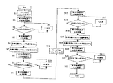
次に、それぞれの情報面毎の、DPP、LPSの調整方法を、図2のフローチャートに沿って説明する。 Next, a method for adjusting DPP and LPS for each information plane will be described with reference to the flowchart of FIG.
本実施の形態の光ディスク装置が起動すると、コントローラ18はスピンドル19を起動、レーザー点灯、フォーカス引き込み等を行う。最初のフォーカス引き込みは、ディスク表面から遠い第2の情報面に引き込むように行われる。
When the optical disk apparatus according to the present embodiment is activated, the controller 18 activates the
調整は、光ディスク1の第2の情報面にフォーカス制御が掛かっている状態で行われる(S1)。 The adjustment is performed in a state where focus control is applied to the second information surface of the optical disc 1 (S1).
トラッキングサーボはオフの状態、つまりSW16が、トラッキング制御回路14、レンズ位置制御回路15のどちらとも接続されていない状態で行われる。
The tracking servo is performed in an off state, that is, in a state where the
フォーカス制御については詳述しないが、光検出器の4つのABCD出力より一般的な非点収差法によってフォーカス誤差信号を検出し、フォーカス制御を掛けている
先ず、K2の調整から行われる。K2は、先ず設計上考えられる最も小さい値の初期値に設定される(S2)。
Although focus control is not described in detail, a focus error signal is detected by a general astigmatism method from four ABCD outputs of the photodetector, and focus control is applied. First, adjustment is performed from K2. First, K2 is set to an initial value of the smallest value that can be considered in design (S2).
その状態で、コントローラ18は、LPSのトラッキングエラー変調成分を観測し、所定量以下かが判断される(S3)。 In this state, the controller 18 observes the tracking error modulation component of the LPS and determines whether it is less than a predetermined amount (S3).
変調成分の観測方法としては、LPSのピークホールド値とボトムホールド値を観測し、その差が所定量以下かで判断する。最大値、最小値を検出しその差でも良い。 As a method for observing the modulation component, the peak hold value and the bottom hold value of LPS are observed, and a determination is made based on whether the difference is equal to or less than a predetermined amount. The maximum value and minimum value may be detected and the difference between them may be used.
所定量以下でない場合K2の値を所定量増加させ、再度LPSのトラッキングエラー成分を検出し、所定量以下になるまで繰り返す(S4)。 If it is not less than the predetermined amount, the value of K2 is increased by a predetermined amount, the tracking error component of LPS is detected again, and the process is repeated until it becomes less than the predetermined amount (S4).
所定量以下になったところのK2の値を第2の情報面での最適値として記憶する(S5)。 The value of K2 that has become equal to or less than the predetermined amount is stored as the optimum value on the second information surface (S5).
この時点で、LPS信号の0点はほぼ工場調整時の中心位置になっている。 At this point, the zero point of the LPS signal is almost the center position during factory adjustment.
次に、コントローラ18は、レンズ位置制御の目標値を0として、レンズ位置制御回路15側にSWを接続し、レンズ位置制御ループをオンとする。これにより、対物レンズは、LPS0となる点へ固定される(S6)。 Next, the controller 18 sets the target value for lens position control to 0, connects the SW to the lens position control circuit 15 side, and turns on the lens position control loop. As a result, the objective lens is fixed to a point that becomes LPS0 (S6).
このときのレンズ位置制御の制御帯域は500Hz程度とし、重力、振動等の外乱に十分耐えられる程度の帯域とする。 The control band for lens position control at this time is about 500 Hz, and is a band that can sufficiently withstand disturbances such as gravity and vibration.
続いて、コントローラ18は、レンズ位置制御の目標値を0を中心とした所定振幅で所定周波数の正弦波で変更する。所定周波数は、例えば10Hz、振幅は対物レンズが±150um程度移動する値とする(S7)。 Subsequently, the controller 18 changes the target value of the lens position control with a sine wave having a predetermined amplitude centered on 0 and a predetermined frequency. For example, the predetermined frequency is 10 Hz, and the amplitude is a value by which the objective lens moves about ± 150 μm (S7).
コントローラ18は、K1の値を第2の情報面での設計上の最適値を初期値として設定する(S8)。 The controller 18 sets the value of K1 as an initial value that is the optimum design value on the second information surface (S8).
このときのK1の初期値をK2の最適値としても良い。ディスク透過層を含む光学系が理想的且つ光学系等が正しく調整されている場合はK1とK2は等しい、K1とK2の差は調整誤差分であり、調整誤差が所定範囲内であれば、K1の初期値としてK2の最適値を与えることは、その後のK1の調整の収束時間短縮に繋がることになる。 The initial value of K1 at this time may be the optimum value of K2. If the optical system including the disk transmission layer is ideal and the optical system is correctly adjusted, K1 and K2 are equal, the difference between K1 and K2 is an adjustment error, and if the adjustment error is within a predetermined range, Giving the optimum value of K2 as the initial value of K1 leads to shortening of the convergence time of the subsequent adjustment of K1.
コントローラ18は、DPP信号の最大値と、最小値の中間値であるオフセット量を検出し、レンズ位置目標値の極性と、オフセットの極性からK1の大きさを増減させる。 The controller 18 detects an offset amount that is an intermediate value between the maximum value and the minimum value of the DPP signal, and increases or decreases the magnitude of K1 from the polarity of the lens position target value and the polarity of the offset.
オフセット量の検出は、DPP信号をピークホールドとボトムホールドし、その中間値をオフセット量とすれば良い。 To detect the offset amount, the DPP signal may be peak-held and bottom-held, and an intermediate value between them may be used as the offset amount.
K1の大きさの、増減は、例えば、メインビーム(MPP)及びサブビーム(SPP)のDCオフセットが、対物レンズが内周側に移動するとマイナスで、外周側でプラスに変化するとして、又、レンズ位置制御の目標値が内周側でマイナス、外周側のときにプラスだとすると、DPP信号はMPP−K1xSPPなので、レンズ位置制御目標値がプラスの時に、DPPのオフセットがプラスということは、補正が足りないということで、K1を大きくすれば良い。逆にレンズ位置制御目標値がプラスの時に、DPPのオフセットがマイナスの場合は、補正し過ぎということでK1を小さくすれば良い。レンズ位置目標値がマイナスの場合はこの逆でDPPのオフセットがマイナスということは、補正が足りないということで、K1を大きく、DPPのオフセットがプラスの場合は、補正し過ぎということでK1を小さくすれば良い。 The magnitude of K1 increases or decreases, for example, when the DC offset of the main beam (MPP) and sub beam (SPP) changes negatively when the objective lens moves to the inner peripheral side and changes positively on the outer peripheral side. If the position control target value is negative on the inner periphery side and positive when it is on the outer periphery side, the DPP signal is MPP-K1xSPP. Therefore, when the lens position control target value is positive, the offset of DPP is positive. It is not necessary to increase K1. On the other hand, if the DPP offset is negative when the lens position control target value is positive, K1 may be reduced because correction is excessive. If the lens position target value is negative, the opposite is the opposite, and the DPP offset is negative. This means that the correction is not enough, and K1 is large. If the DPP offset is positive, K1 is overcorrected. Just make it smaller.
正弦波一周期の間、DPPのオフセットの変化量が所定範囲内となるまで、これを繰り返す(S9,S10)。 This is repeated until the amount of change in the DPP offset falls within a predetermined range during one sine wave cycle (S9, S10).
所定範囲内となったら、その時のK1の値を第2の情報面の最適値として記憶(S11)。このように調整することで、第2の情報面のK1,K2をLPS,DPPそれぞれの最適値に調整することが可能である。 If it is within the predetermined range, the value of K1 at that time is stored as the optimum value of the second information surface (S11). By adjusting in this way, it is possible to adjust K1 and K2 of the second information surface to the optimum values of LPS and DPP, respectively.
今後、コントローラ18は、このときのK1,K2を第2の情報面の最適値として、第2の情報面にあるときは、このK1,K2の値を設定して使用する。 From now on, the controller 18 sets K1 and K2 at this time as the optimum values of the second information surface, and sets and uses the values of K1 and K2 when they are on the second information surface.
次に、トラッキング制御はオフの状態のままで、第1の情報面へフォーカスジャンプを行う(S12)。 Next, a focus jump is performed to the first information surface while the tracking control is off (S12).
フォーカスジャンプが終了したら、続いて、第1の情報面での、K1,K2の調整を開始する。先ず、K2の調整から行われる。 When the focus jump is finished, the adjustment of K1 and K2 on the first information surface is started. First, K2 is adjusted.
K2は、先ず設計上考えられる最も小さい値の初期値に設定される(S13)。 First, K2 is set to an initial value of the smallest value that can be considered in design (S13).
その状態で、コントローラ18は、LPSのトラッキングエラー変調成分を観測し、所定量以下かが判断される(S14)。 In this state, the controller 18 observes the tracking error modulation component of the LPS, and determines whether it is less than a predetermined amount (S14).
所定量以下でない場合K2の値を所定量増加させ、再度LPSのトラッキングエラー成分を検出し、所定量以下になるまで繰り返す(S15)。 If it is not less than the predetermined amount, the value of K2 is increased by a predetermined amount, the tracking error component of LPS is detected again, and the process is repeated until it becomes less than the predetermined amount (S15).
所定量以下になったところのK2の値を第1の情報面の最適値として記憶する(S16)。この時点で、LPS信号の0点はほぼ工場調整時の中心位置になっている。 The value of K2 that has become the predetermined amount or less is stored as the optimum value of the first information surface (S16). At this point, the zero point of the LPS signal is almost the center position during factory adjustment.
次に、コントローラ18は、レンズ位置制御の目標値を0として、レンズ位置制御回路15側にSWを接続し、レンズ位置制御ループをオンとする。これにより、対物レンズは、LPS0となる点へ固定される(S17)。このときのレンズ位置制御の制御帯域は500Hz程度とし、重力、振動等の外乱に十分耐えられる程度の帯域とする。 Next, the controller 18 sets the target value for lens position control to 0, connects the SW to the lens position control circuit 15 side, and turns on the lens position control loop. As a result, the objective lens is fixed to a point that becomes LPS0 (S17). The control band for lens position control at this time is about 500 Hz, and is a band that can sufficiently withstand disturbances such as gravity and vibration.
続いて、コントローラ18は、レンズ位置制御の目標値を0を中心とした所定振幅で所定周波数の正弦波で変更する。所定周波数は、例えば10Hz、振幅は対物レンズが±150um程度移動する値とする(S18)。 Subsequently, the controller 18 changes the target value of the lens position control with a sine wave having a predetermined amplitude centered on 0 and a predetermined frequency. The predetermined frequency is, for example, 10 Hz, and the amplitude is a value by which the objective lens moves about ± 150 μm (S18).
コントローラ18は、K1の値を第1の情報面での設計上の最適値を初期値として設定する(S19)。 The controller 18 sets the value of K1 as an initial value that is the optimum design value on the first information surface (S19).
コントローラ18は、DPP信号の最大値と、最小値の中間値であるオフセット量を検出し、レンズ位置目標値の極性と、オフセットの極性からK1の大きさを増減させる。正弦波一周期の間、DPPのオフセットの変化量が所定範囲内となるまで、これを繰り返す(S20,S21)。 The controller 18 detects an offset amount that is an intermediate value between the maximum value and the minimum value of the DPP signal, and increases or decreases the magnitude of K1 from the polarity of the lens position target value and the polarity of the offset. This is repeated until the amount of change in the DPP offset falls within a predetermined range during one sine wave cycle (S20, S21).
所定範囲内となると、その時のK1の値を第1の情報面の最適値として記憶する(S22)。このように調整することで、第1の情報面のK1,K2をLPS,DPPそれぞれの最適値に調整することが可能である。 When it is within the predetermined range, the value of K1 at that time is stored as the optimum value of the first information surface (S22). By adjusting in this way, it is possible to adjust K1 and K2 of the first information surface to optimum values of LPS and DPP, respectively.
今後、コントローラ18は、このときのK1,K2を第1の情報面の最適値として、第1の情報面にあるときは、このK1,K2の値を設定して使用する。 From now on, the controller 18 sets K1 and K2 at this time as the optimum values of the first information surface, and sets and uses the values of K1 and K2 when they are on the first information surface.
以上、第2の情報面、第1の情報面の順番にそれぞれ調整して、全ての調整が終了する。 As described above, the adjustment is performed in the order of the second information surface and the first information surface, and all the adjustments are completed.
本実施の形態では、ディスク表面から遠い第2の情報面から調整を行ったが、第1の情報面から先に調整を行っても良い。 In this embodiment, the adjustment is performed from the second information surface far from the disk surface. However, the adjustment may be performed first from the first information surface.
本実施の形態において、第2の情報面から先に行ったのは、単層のディスクの場合に、2層の場合の第2の情報面の位置に情報面がある場合を考えているからであり、この位置を最初の目標とすることで、ディスクの層の数を気にしないで、最初の調整が可能となるからである。 In the present embodiment, the reason why the second information surface is performed first is that, in the case of a single-layer disc, the case where there is an information surface at the position of the second information surface in the case of two layers is considered. This is because by making this position the first target, the first adjustment is possible without worrying about the number of layers of the disk.
又、本実施の形態においては、トラッキング制御オフ状態で、全ての層の調整が完了するので、調整の終わっていないDPP信号でトラッキング制御をオンする必要がない。 In the present embodiment, since the adjustment of all the layers is completed in the tracking control off state, it is not necessary to turn on the tracking control with the DPP signal that has not been adjusted.
又、K1調整時に対物レンズを所定量移動させなければならないが、先に調整したLPS信号によりレンズ位置制御をかけながら、所定量移動させることができるので、重力、振動等の外乱によらず、安定して、動作範囲内での調整が可能となる。 In addition, the objective lens must be moved by a predetermined amount during the K1 adjustment, but can be moved by a predetermined amount while applying the lens position control by the previously adjusted LPS signal, so that it is not affected by disturbances such as gravity and vibration. Stable and adjustable within the operating range.
又、K1調整時の、レンズ位置制御の目標値を正弦波としたが、ランプ波、三角波、方形波等、所定量対物レンズ位置を移動させることができる波形であれば何でも良い。 In addition, although the target value for lens position control at the time of K1 adjustment is a sine wave, any waveform that can move the objective lens position by a predetermined amount, such as a ramp wave, a triangular wave, or a square wave, may be used.
又、本実施の形態において、K2の調整が終わるまでの間も、目標値を0としたレンズ位置制御をオンとしておくことも可能である。この場合、トラッキングエラー変調成分の高い周波数成分に応答しないように、レンズ位置制御の制御帯域は、100Hz程度として、重力による対物レンズの移動を抑える程度のものとするのが良い。 In this embodiment, it is also possible to turn on the lens position control with the target value set to 0 until the adjustment of K2 is completed. In this case, in order not to respond to a high frequency component of the tracking error modulation component, the control band of the lens position control is preferably set to about 100 Hz so as to suppress the movement of the objective lens due to gravity.
このようにすることで、DPP,LPSどの調整においても、レンズ位置制御がオンとすることができ、重力、振動などの外乱によらず、安定して、動作範囲内での調整が可能となる。 By doing so, the lens position control can be turned on in any adjustment of DPP and LPS, and the adjustment within the operation range can be stably performed regardless of disturbances such as gravity and vibration. .
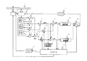
又、図1でのMPP信号,DPP信号,LPS信号の演算回路は、再生専用ディスクのように、K1,K2の調整時から、レーザーパワーやディスクの反射率が変化しない場合には良いが、記録再生可能なディスクのように、記録パワーによるレーザーパワーの変化やディスク内の記録、未記録状態での反射率の変化等がある場合には、図3に示す演算回路の構成が必要である。 In addition, the MPP signal, DPP signal, and LPS signal calculation circuit in FIG. 1 may be used when the laser power and the disk reflectivity do not change after the adjustment of K1 and K2, as in the case of a read-only disk. When there is a change in laser power due to recording power, recording in the disk, change in reflectance in an unrecorded state, etc., as in a recordable / reproducible disc, the configuration of the arithmetic circuit shown in FIG. 3 is necessary. .
図3について簡単に説明する。 FIG. 3 will be briefly described.
図1の演算回路と異なるところは、21〜26の加算回路及び除算回路が追加されているところである。MPP信号は、(A+D)−(B+C)を加算回路25の出力{(A+D)+(B+C)}で除算(除算回路26)したものであり、SPP信号は、(E−F)信号を、加算回路21の出力(E+F)で除算(除算回路23)したものと、(G−H)信号を、加算回路22の出力(G+H)で除算(除算回路24)したものを加算回路9で加算したものとなる。3つのビームそれぞれのプッシュプル信号を、それぞれのビームの総和信号で除算することで、ビームごとに正規化している。このように構成することで、レーザーパワーの変化や、ディスク内の反射率の変化によらず、MPP信号の振幅が得られ、ディスク毎に正確な球面収差の補正が可能であるとともに、K1,K2の調整で最適なDPP信号,LPS信号が得られる。
The difference from the arithmetic circuit of FIG. 1 is that 21 to 26 addition circuits and division circuits are added. The MPP signal is obtained by dividing (A + D)-(B + C) by the output {(A + D) + (B + C)} of the adder circuit 25 (divider circuit 26), and the SPP signal is obtained by dividing the (EF) signal by The
<実施の形態2>
図4は本発明によるDPPの調整を実現した光ディスク装置のブロック図である。
<
FIG. 4 is a block diagram of an optical disc apparatus realizing DPP adjustment according to the present invention.
実施の形態1では、光学ヘッド内で、球面収差を補正する素子を持たない場合の例を説明したが、本実施の形態では、光学ヘッド2内に球面収差を補正する素子を持った場合の例を説明する。
In the first embodiment, an example in which an element for correcting spherical aberration is not provided in the optical head has been described. However, in the present embodiment, a case in which an element for correcting spherical aberration is provided in the
図4において、1は、光ディスク、2は、光ヘッド、3は光ヘッド内の光検出器、A〜Hは、その光検出器の分割パターンの1つずつ、4〜13はDPP信号及びLPS信号生成のための加減乗算等の演算回路、14はDPP信号を入力とするトラッキング制御回路、15はLPS信号を入力とするレンズ位置制御回路、16はスイッチ、17はトラッキングアクチュエータを駆動するためのドライバ回路、18はコントローラ、19はスピンドルで、20は球面収差発生手段を動作させるためのドライバ回路、21はMPP信号振幅測定回路である。 In FIG. 4, 1 is an optical disk, 2 is an optical head, 3 is a photodetector in the optical head, A to H are one of the division patterns of the photodetector, and 4 to 13 are a DPP signal and LPS. An arithmetic circuit such as addition / subtraction / multiplication for signal generation, 14 is a tracking control circuit that receives a DPP signal, 15 is a lens position control circuit that receives an LPS signal, 16 is a switch, and 17 is for driving a tracking actuator. A driver circuit, 18 is a controller, 19 is a spindle, 20 is a driver circuit for operating the spherical aberration generating means, and 21 is an MPP signal amplitude measuring circuit.
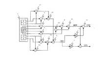
光学ヘッド2は、図5で示すように構成される。
The
図5において、半導体レーザー101から出射したビームは、回折格子102で3ビームに分けられ、コリメーター103で平行光とされ、ビーム整形付き偏光ビームスプリッター104に入射する。ビームの一部は反射させられ、AP用センサー105に入射し、半導体レーザー101からの出射光量のモニターに利用される。透過したビームは、1/4波長板106、レンズ107、レンズ108を介して、対物レンズ112により、光ディスク1上で光透過層を経て記録層面へ集光され、情報の再生、記録に利用される。光ディスク1で反射されたビームは、ビーム整形付き偏光ビームスプリッター104で反射させられ、センサーレンズ114を介して光検出器3に入射し、情報信号の再生に利用される。
In FIG. 5, the beam emitted from the
ここで、レンズ107、レンズ108は、レンズ107は固定、レンズ108は、電磁駆動手段110によりレンズ107との光軸方向の間隔が可変であるように保持されて、球面収差発生手段111を形成している。レンズ107、レンズ108の形状、硝材は、レンズ間隔が変わった時に球面収差のみが発生するように構成されている。電磁駆動手段110は、ステッピングモータを用いてリードスクリューによりミクロンオーダーでレンズ108を移動させるものである。 Here, the lens 107 and the lens 108 are fixed so that the lens 107 is fixed, and the lens 108 is held by the electromagnetic driving means 110 so that the distance in the optical axis direction from the lens 107 is variable, thereby forming the spherical aberration generating means 111. is doing. The shape of the lens 107 and the lens 108 and the glass material are configured such that only spherical aberration occurs when the lens interval changes. The electromagnetic drive means 110 moves the lens 108 on the micron order with a lead screw using a stepping motor.
レンズ108の移動20umにつき、ディスク上の最適なフォーカス位置が1um程度変わるように設計されている。この割合は、光学系の設計によるもので、使用目的により最適な割合に決定される。 It is designed so that the optimum focus position on the disk changes by about 1 μm per 20 μm movement of the lens 108. This ratio depends on the design of the optical system, and is determined to be an optimal ratio depending on the purpose of use.
球面収差発生手段111は、2層のディスクに対応できるように、十分広い収差発生範囲を持ち、ステッピングモータを用いてリードスクリューによりミクロンオーダーでレンズ108を移動させるものである。 The spherical aberration generating means 111 has a sufficiently wide aberration generating range so as to be compatible with a two-layer disc, and moves the lens 108 on the micron order with a lead screw using a stepping motor.
DPP信号。LPS信号の演算方法は、実施の形態1と同じである。 DPP signal. The LPS signal calculation method is the same as that of the first embodiment.
DPP信号は、トラッキング制御回路14を経て、スイッチ16に入力され、LPS信号はレンズ位置制御回路15を経て、スイッチ16のもう一方の端子に入力される。SW16は、コントローラ18で制御され、トラッキング制御時は、トラッキング制御回路14側、レンズ位置制御時は、レンズ位置制御回路15側に接続され、ドライバ17を介して、光学ヘッド内のトラッキングアクチュエータに接続され、それぞれの制御ループを構成する。
The DPP signal is input to the
又、コントローラ18は、光ヘッド2内の、図5に示す球面収差発生手段111を、ドライバ回路20をコントロールすることで球面収差を最適な状態に調整する。
Further, the controller 18 controls the spherical aberration generating means 111 shown in FIG. 5 in the
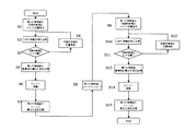
次に、それぞれの情報面毎の、球面収差、DPP,LPSの調整方法を図6のフローチャートに沿って説明する。 Next, a method for adjusting spherical aberration, DPP, and LPS for each information surface will be described with reference to the flowchart of FIG.
本実施の形態の光ディスク装置が起動すると、コントローラ18は、スピンドル19を起動、レーザー点灯、フォーカス引き込み等を行う。最初のフォーカス引き込みは、ディスク表面から遠い第2の情報面で行われる。調整は、光ディスク1の第2の情報面にフォーカス制御が掛かっている状態で行われる。フォーカス制御については詳述しないが、光検出器の4つのABCD出力より一般的な非点収差法によってフォーカス誤差信号を検出し、フォーカス制御を掛けている
調整は先ず球面収差補正から始められる。
When the optical disk apparatus according to the present embodiment is activated, the controller 18 activates the
球面収差補正ルーチンがスタートすると、先ず、球面収差発生手段111を予め決められたスタート位置とする(S1)。 When the spherical aberration correction routine starts, first, the spherical aberration generating means 111 is set to a predetermined start position (S1).
例えば、第2の情報面の媒体基板厚が標準である場合に、第2の情報面上で球面収差がなくなるような収差を与える設計値上の基準位置から所定量外れた位置である。この球面収差発生量を−4とする。これは例えば1単位当たりレンズ108を10μm移動させるものとする。レンズ108の移動量が20umで、球面収差の適切な焦点位置が1um動くので、球面収差発生量1は焦点位置では、0.5um単位となる。−4はレンズ107に近づく方向に基準位置から40μmレンズ108を移動させた状態である。この状態は、設計上では第2の情報面までの媒体基板厚が厚い方向に2um増えた時に、球面収差が最適な状態になる位置である。
For example, when the medium substrate thickness of the second information surface is standard, the position is deviated by a predetermined amount from the reference position on the design value that gives aberration that eliminates spherical aberration on the second information surface. The amount of spherical aberration generated is −4. For example, the lens 108 is moved by 10 μm per unit. Since the movement amount of the lens 108 is 20 μm and the appropriate focal position of the spherical aberration is moved by 1 μm, the spherical
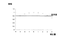
次に、コントローラ18は、メインビームのプッシュプル信号であるMPP信号の出力信号振幅をMPP信号振幅測定回路21より入力し、補正量−4と関連付けて評価指標としてメモリ等に記憶する(S2)。
Next, the controller 18 inputs the output signal amplitude of the MPP signal, which is a push-pull signal of the main beam, from the MPP signal
次に、コントローラ18は、球面収差球面収差発生手段がエンド位置であるかを確認する(S3)。 Next, the controller 18 confirms whether the spherical aberration spherical aberration generating means is at the end position (S3).
エンド位置は、球面収差発生量にして+4とし、基準位置からレンズ107から遠ざかる方法に40umレンズ108を移動させた状態である。この状態は、設計上では第2の情報面の媒体基板厚が薄い方向に2um減った時に、球面収差が最適な状態になる位置である。 The end position is a state where the spherical aberration generation amount is set to +4, and the 40 um lens 108 is moved in a method of moving away from the lens 107 from the reference position. This state is a position where the spherical aberration is in an optimum state when the medium substrate thickness of the second information surface is reduced by 2 μm in the direction of design.
エンド位置でない場合は、エンド位置になるまで球面収差補正量を1ずつ増加させ(S4)MPP信号振幅測定回路21でMPP振幅を測定、補正量と関連づけて記憶する(S2)。補正量を1ずつ増加させているので、レンズ108を10μmずつ動かし、その場所でのMPP振幅を測定していることになる。
If it is not the end position, the spherical aberration correction amount is incremented by 1 until the end position is reached (S4), and the MPP signal
MPP信号振幅測定回路21は、MPP信号の振幅をピークホールド回路とボトムホールド回路等で求めるような構成のもので良い。又、MPP振幅をAD変換器で取り込みMAX値とMIN値を記憶しておくような方法でも良い。
The MPP signal
補正量を横軸にMPP振幅値を縦軸にグラフ化すると図7の○で表したようなグラフが描かれる。最適な球面収差補正量を求めるために記憶された補正量に関連づけられたMPP振幅値を使用する。MPP振幅値が基準値を越える2箇所の補正量を求め、この2箇所の補正量の中央値を最適な球面収差補正量とする。離散的な補正量から最適な球面収差補正量を正確に求めるため、各補正量から線形補間等で基準値超える補正量を求める。図7の○の例ではマイナス側で基準値を跨ぐ補正量は−3.0プラス側では3.3であるので、最適な球面収差補正量は0.15と求まる。 When the correction amount is plotted on the horizontal axis and the MPP amplitude value is plotted on the vertical axis, a graph represented by a circle in FIG. 7 is drawn. The MPP amplitude value associated with the stored correction amount is used to determine the optimum spherical aberration correction amount. Two correction amounts where the MPP amplitude value exceeds the reference value are obtained, and the median value of the two correction amounts is set as the optimum spherical aberration correction amount. In order to accurately obtain the optimum spherical aberration correction amount from the discrete correction amount, a correction amount exceeding the reference value is obtained from each correction amount by linear interpolation or the like. In the example of ○ in FIG. 7, the correction amount straddling the reference value on the minus side is 3.3 on the −3.0 plus side, so the optimum spherical aberration correction amount is found to be 0.15.
決定された補正量を第2の情報面の補正量として記憶する(S5)。 The determined correction amount is stored as the correction amount of the second information surface (S5).
以上により球面収差の補正が終わる。続いて、DPP,LPS信号のK1,K2の調整を行う。この調整方法は、実施の形態1の調整方法と同じであるため、ここでの説明は省略する(S6)。
The spherical aberration correction is thus completed. Subsequently, K1 and K2 of the DPP and LPS signals are adjusted. Since this adjustment method is the same as the adjustment method of
K1,K2の値が決定されると、その値を第2の情報面の値として記憶する(S7)。 When the values of K1 and K2 are determined, the values are stored as values of the second information surface (S7).
次に、トラッキング制御はオフの状態のままで、球面収差発生手段111を第1の情報面の設計上の最適値として第1の情報面へフォーカスジャンプを行う(S8)。 Next, the tracking control is kept in an off state, and the spherical aberration generating means 111 is made a focus jump to the first information surface as the optimum value for designing the first information surface (S8).
フォーカスジャンプが終了すると、球面収差発生手段111を予め決められた第1の情報面のスタート位置とする(S9)。 When the focus jump is finished, the spherical aberration generating means 111 is set to a predetermined first information surface start position (S9).
スタート位置は、例えば第1の情報面の媒体基板厚が標準である場合に、第1の情報面上で球面収差がなくなるような収差を与える設計値上の基準位置から所定量外れた位置である。ここでの基準位置は、最初に行った第2の情報面の基準位置とは異なる。第2の情報面と、第1の情報面とは、25um離れていて、第1の情報面はディスク表面に近い側であるので、第2の情報面での基準位置から第1の情報面での基準位置は、500umレンズ107から遠ざかる方向に離れている。第1の情報面のスタート位置は、この位置から所定量外れた位置から始まる。
The start position is, for example, a position that deviates a predetermined amount from a reference position on the design value that gives an aberration that eliminates spherical aberration on the first information surface when the medium substrate thickness of the first information surface is standard. is there. The reference position here is different from the first reference position of the second information surface. Since the second information surface and the first information surface are separated by 25 μm and the first information surface is closer to the disc surface, the first information surface is determined from the reference position on the second information surface. The reference position at is away from the 500 um lens 107. The start position of the first information surface starts from a position deviated by a predetermined amount from this position.
この球面収差発生量を−4とする。−4はレンズ7に近づく方向に基準位置から40μmレンズ108を移動させた状態である。この状態は、設計上では第1の情報面までの媒体基板厚が厚い方向に2um増えた時に、球面収差が最適な状態になる位置である。 The amount of spherical aberration generated is −4. Reference numeral -4 denotes a state in which the 40 μm lens 108 is moved from the reference position in a direction approaching the lens 7. This state is a position where the spherical aberration becomes optimal when the medium substrate thickness up to the first information surface is increased by 2 μm in the design direction.
次に、コントローラ18は、メインビームのプッシュプル信号であるMPP信号の出力信号振幅をMPP信号振幅測定回路21より入力し、補正量−4と関連付けて評価指標としてメモリ等に記憶する(S10)。
Next, the controller 18 inputs the output signal amplitude of the MPP signal, which is a push-pull signal of the main beam, from the MPP signal
次に、コントローラ18は、球面収差球面収差発生手段がエンド位置であるかを確認する(S11)。 Next, the controller 18 confirms whether the spherical aberration spherical aberration generating means is at the end position (S11).
エンド位置は、球面収差発生量にして+4とし、基準位置からレンズ107から遠ざかる方法に40umレンズ108を移動させた状態である。この状態は、設計上では第1の情報面が、媒体基板厚が薄い方向に2um減った時に、球面収差が最適な状態になる位置である。 The end position is a state where the spherical aberration generation amount is set to +4, and the 40 um lens 108 is moved in a method of moving away from the lens 107 from the reference position. This state is a position where the spherical aberration is in an optimum state when the first information surface is reduced by 2 μm in the direction in which the thickness of the medium substrate is thin.
エンド位置でない場合は、エンド位置になるまで球面収差補正量を1ずつ増加させ(S12)、MPP信号振幅測定回路21でMPP振幅を測定、補正量と関連づけて記憶する(S10)。補正量を1ずつ増加させているので、レンズ108を10μmずつ動かし、その場所でのMPP振幅を測定していることになる。
If it is not the end position, the spherical aberration correction amount is increased by 1 until the end position is reached (S12), and the MPP signal
MPP信号振幅測定回路21の構成は、第2の情報面で行った方法と同じである。又、補正量と、MPP振幅値より、最適な球面収差補正量を決定する方法も同じである。決定された補正量を第1の情報面の補正量として記憶する(S13)。
The configuration of the MPP signal
以上により球面収差の補正が終わる。 The spherical aberration correction is thus completed.
続いて、DPP,LPS信号のK1,K2の調整を行う。 Subsequently, K1 and K2 of the DPP and LPS signals are adjusted.
この調整方法は、実施の形態1の調整方法と同じであるため、これについての再度の説明は省略する(S14)。
Since this adjustment method is the same as the adjustment method of
K1,K2の値が決定されると、その値を、第1の情報面の値として記憶する(S15)。 When the values of K1 and K2 are determined, the values are stored as values of the first information surface (S15).
以上で、各情報面の球面収差補正量と、DPP,LPSの係数K1,K2の調整を終了する。 This completes the adjustment of the spherical aberration correction amount of each information surface and the DPP and LPS coefficients K1 and K2.
各情報面での記録再生は、各情報面毎の調整値を用いて行われる。 Recording / reproduction on each information surface is performed using an adjustment value for each information surface.
本実施の形態においては、トラッキング制御オフ状態で、それぞれの情報面全ての調整が完了するので、調整の終わっていないDPP信号でトラッキング制御をオンする必要がない。 In this embodiment, since the adjustment of all the information surfaces is completed in the tracking control off state, it is not necessary to turn on the tracking control with a DPP signal for which adjustment has not been completed.
又、各情報面ごとに、球面収差の調整を先に行い、その後、DPP,LPSの調整を行うことにより、調整終了後には、球面収差、DPP,LPS信号すべてが最適値になっており、すぐに記録再生動作に移ることができる。 In addition, by adjusting spherical aberration first for each information surface, and then adjusting DPP and LPS, the spherical aberration, DPP and LPS signals are all optimum values after adjustment. The recording / playback operation can be immediately started.
又、本実施の形態では、球面収差補正手段として図5のような光学系を用いたが、液晶素子等、球面収差発生により、DPP信号に影響の出る系であれば、どのようなものでも適用可能である。 In this embodiment, the optical system as shown in FIG. 5 is used as the spherical aberration correcting means. However, any system such as a liquid crystal element that affects the DPP signal due to the occurrence of spherical aberration can be used. Applicable.
又、本実施の形態では、2層のディスクを例に挙げたが、2層に限定されずに、何層でも層毎に調整を行うことで対応可能である。 In the present embodiment, a two-layer disc has been described as an example. However, the number of layers is not limited to two, and any number of layers can be dealt with by adjusting each layer.
1 光ディスク
2 光学ピックアップ
3 光検出器
4,7,8,12 減算器
5,6,9,13 加算器
10,11 乗算器
14 トラッキング制御回路
15 レンズ位置制御回路
16 スイッチ
17 ドライバ
18 コントローラ
19 スピンドル
20 球面収差素子ドライバ
21 MPP振幅測定回路
22 再生信号振幅測定回路
DESCRIPTION OF
Claims (2)
前記光記録媒体の、複数の記録再生情報面毎に、前記第1の所定比率と前記第2の所定比率をそれぞれ調整する調整手段を持つことを特徴とする光学的情報記録再生装置。 A light beam from a light source is divided into a main beam and first and second sub beams by a wavefront splitting element disposed between the light source and an objective lens, and is focused on an optical recording medium having a plurality of recording / reproducing surfaces by the objective lens. Then, reflected light from the optical recording medium of the main beam and the first and second sub beams is received by a photodetector, and a tracking control signal and a lens position detection signal are obtained from the output from the photodetector. An apparatus for generating a tracking error signal and a lens position detection signal, wherein a push-pull signal of a main beam by an output from the detector and a push-pull signal of first and second sub beams by an output from the detector The first and second sub-beam push-pull signals are amplified at a first predetermined ratio and then differential with the main beam push-pull signal. The objective lens is obtained by obtaining a tracking signal, amplifying the push-pull signal of the first and second sub-beams at a second predetermined ratio, and taking a difference from the push-pull signal of the main beam. In an optical information recording / reproducing apparatus for obtaining a signal related to the position of
An optical information recording / reproducing apparatus comprising adjusting means for adjusting the first predetermined ratio and the second predetermined ratio for each of a plurality of recording / reproducing information surfaces of the optical recording medium.
Priority Applications (1)
| Application Number | Priority Date | Filing Date | Title |
|---|---|---|---|
| JP2005008219A JP2006196121A (en) | 2005-01-14 | 2005-01-14 | Optical information recording and reproducing device |
Applications Claiming Priority (1)
| Application Number | Priority Date | Filing Date | Title |
|---|---|---|---|
| JP2005008219A JP2006196121A (en) | 2005-01-14 | 2005-01-14 | Optical information recording and reproducing device |
Publications (1)
| Publication Number | Publication Date |
|---|---|
| JP2006196121A true JP2006196121A (en) | 2006-07-27 |
Family
ID=36802071
Family Applications (1)
| Application Number | Title | Priority Date | Filing Date |
|---|---|---|---|
| JP2005008219A Withdrawn JP2006196121A (en) | 2005-01-14 | 2005-01-14 | Optical information recording and reproducing device |
Country Status (1)
| Country | Link |
|---|---|
| JP (1) | JP2006196121A (en) |
Cited By (2)
| Publication number | Priority date | Publication date | Assignee | Title |
|---|---|---|---|---|
| JP2011192369A (en) * | 2010-03-17 | 2011-09-29 | Hitachi Media Electoronics Co Ltd | Optical disk device |
| JP2012190525A (en) * | 2011-03-14 | 2012-10-04 | Fujitsu Ten Ltd | Optical disk device, signal processor, and signal processing method |
-
2005
- 2005-01-14 JP JP2005008219A patent/JP2006196121A/en not_active Withdrawn
Cited By (2)
| Publication number | Priority date | Publication date | Assignee | Title |
|---|---|---|---|---|
| JP2011192369A (en) * | 2010-03-17 | 2011-09-29 | Hitachi Media Electoronics Co Ltd | Optical disk device |
| JP2012190525A (en) * | 2011-03-14 | 2012-10-04 | Fujitsu Ten Ltd | Optical disk device, signal processor, and signal processing method |
Similar Documents
| Publication | Publication Date | Title |
|---|---|---|
| JP4443471B2 (en) | Disc discriminating method and optical disc apparatus | |
| JP4357518B2 (en) | Optical head and optical disc apparatus including the same | |
| US20060098540A1 (en) | Optical information recording/reproducing apparatus comprising spherical aberration mechanism | |
| US7307927B2 (en) | Optical disk apparatus and method for recording and reproducing an optical disk | |
| JP2006286132A (en) | Disk drive unit and spherical aberration compensation method | |
| JP2006139841A (en) | Optical disk recording/reproducing device | |
| US8345521B2 (en) | Optical disc apparatus and signal generation method | |
| JP2006196121A (en) | Optical information recording and reproducing device | |
| JP4991189B2 (en) | Optical disc apparatus and tracking method | |
| US7894313B2 (en) | Optical disc recording and reproducing apparatus | |
| JP2003217142A (en) | Method for detecting optical disk focus error and optical disk apparatus | |
| US20070280085A1 (en) | Optical disc device and optical pickup | |
| US20060221797A1 (en) | Optical pickup, optical recording and/or reproducing apparatus using the same, and method for detecting tracking error signal | |
| JP5463118B2 (en) | Optical disk device | |
| JP4345620B2 (en) | Optical information recording apparatus, optical information reproducing apparatus, optical information recording method, and optical information reproducing method | |
| JP2002190125A (en) | Optical head device, optical information recording/ reproducing apparatus, method for detecting aberration, and method of adjusting optical head device | |
| JP2006521646A (en) | Method and apparatus for measuring the tilt of an optical disc | |
| JP2006260706A (en) | Optical information recording and reproducing method | |
| JP5055411B2 (en) | Optical disk apparatus and optical disk apparatus adjustment method | |
| JP4332799B2 (en) | Optical pickup, disk drive device, and adjustment value detection method for focus bias and spherical aberration in optical pickup | |
| JP2009140573A (en) | Optical disk drive and focus jump method | |
| JP4103137B2 (en) | Aberration correction apparatus and aberration correction method in optical disc apparatus | |
| JP6288233B2 (en) | Optical pickup device and optical disk device | |
| JP4158114B2 (en) | Optical pickup and disk drive device | |
| JP5264212B2 (en) | Optical information recording / reproducing apparatus |
Legal Events
| Date | Code | Title | Description |
|---|---|---|---|
| A300 | Withdrawal of application because of no request for examination |
Free format text: JAPANESE INTERMEDIATE CODE: A300 Effective date: 20080401 |