JP2006193257A - Elevator rope holding device, and installing method thereof - Google Patents
Elevator rope holding device, and installing method thereof Download PDFInfo
- Publication number
- JP2006193257A JP2006193257A JP2005005360A JP2005005360A JP2006193257A JP 2006193257 A JP2006193257 A JP 2006193257A JP 2005005360 A JP2005005360 A JP 2005005360A JP 2005005360 A JP2005005360 A JP 2005005360A JP 2006193257 A JP2006193257 A JP 2006193257A
- Authority
- JP
- Japan
- Prior art keywords
- rope
- main
- elevator
- main body
- guide rails
- Prior art date
- Legal status (The legal status is an assumption and is not a legal conclusion. Google has not performed a legal analysis and makes no representation as to the accuracy of the status listed.)
- Pending
Links
Images


Abstract
Description
この発明は、エレベータのメインロープの設置や交換時にそのエレベータの昇降路内でメインロープを把持して固定するために使用するロープ把持装置およびその把持装置の据え付け方法に関する。 The present invention relates to a rope gripping apparatus used for gripping and fixing a main rope in a hoistway of the elevator when installing or replacing the main rope of the elevator, and an installation method of the gripping apparatus.
図15にはエレベータのメインロープを交換する作業時の状態を示してあり、1が建屋内に設けられた昇降路で、この昇降路1の上端部に機械室2が設けられ、この機械室2内に巻上機3が設置されている。 FIG. 15 shows a state at the time of exchanging the main rope of the elevator. Reference numeral 1 denotes a hoistway provided in the building, and a machine room 2 is provided at the upper end of the hoistway 1. A hoisting machine 3 is installed in 2.
巻上機3のシーブ3aには複数本のメインロープ4が並列して巻き掛けられ、これらメインロープ4が昇降路1内に引き下げられ、その一端部に乗りかご5が、他端部にカウンターウエイト6がそれぞれ取り付けられ、これら乗りかご5とカウンターウエイト6とが重量的にほぼ釣り合った状態で巻上機3により乗りかご5が駆動されて昇降路1内で昇降する。なお、7はメインロープ4を巻上機3からそらすためのそらせ車である。
A plurality of
メインロープ4の交換時には、乗りかご5を昇降路1内の上部に上昇させ、その乗りかご5をチェーンブロック10を用いて支持するとともに、カウンターウエイト6をピット11に設置した梁部材12を介して支持する。また、上昇した乗りかご5とほぼ同じレベルの位置において昇降路1内にロープ把持装置13を設け、このロープ把持装置13でメインロープ4の途中を把持して固定する。
When exchanging the
そして把持装置13の直上の部分でメインロープ4を切断し、その上部側を撤去し、また下部側を把持装置13から取り外して撤去する。次に、新しいメインロープ4aを巻上機3およびそらせ車7に通し、その途中を把持装置13で把持し、この状態でメインロープ4aの一端側の端部を乗りかご5に連結し、他端側の端部をカウンターウエイト6に連結し、最後にメインロープ4aを把持装置13から取り外す。
Then, the
従来のロープ把持装置13の構造を図16(A),(B)に示してあり、14はカウンターウエイト用のガイドレールで、これらガイドレール14にそれぞれブラケット15が締結具16を介して取り付けられ、これらブラケット15間に支持梁17がボルト18を介して水平に取り付けられる。
The structure of the conventional
把持装置13は、メインロープ4,4aを把持する把持機構を備え、この把持機構は締結具19により支持梁17の前面に固定されるロープ固定板20と、このロープ固定板20に前記締結具19および平座金21、ばね座金22、ナット23を介して固定されるロープクリップ24とを有し、前記ロープ固定板20とロープクリップ24とで旧のメインロープ4や新のメインロープ4aを挟み、ナット23を締め付けてそのメインロープ4,4aを強固に把持して固定するようになっている。
The
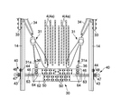
図17ないし図21には従来の別のロープ把持装置13を示してある。この把持装置13は支持梁30を備え、この支持梁30は吊り部材としての一対のチェーンブロック31を用いて平行に並んだ一対のガイドレール14間に水平に吊り下げられている。すなわち、ガイドレール14の継目部分の背面に設けられた目板33に玉掛けワイヤ34が掛けられ、この玉掛けワイヤ34にチェーンブロック31が掛けられている。そしてチェーンブロック31のシャックル31aが支持梁30に取り付けられた吊り金具36に掛け止められ、これにより支持梁30がガイドレール14間に水平に吊り下げられている。
17 to 21 show another conventional
支持梁30の両端部側には、支持梁30の前後左右の振れ動きを防止する振れ止め機構40が設けられている。この振止め機構40は振れ止め板43を備え、この振れ止め板43はクリップ・ボルト部材44を介してガイドレール14の背面に固定されている。そしてこの振れ止め板43にスリット45が形成され、このスリット45に支持梁30の端部が挿入され、これにより支持梁30の前後の振れが抑えられている。
On both ends of the
支持梁30の両端部には左右方向に長い長孔46が形成され、この長孔46にボルト・ナット部材47が挿入され、またこのボルト・ナット部材47に対して断面L状の押え板48が装着されている。そして、ボルト・ナット部材47を長孔46に沿ってスライドし、押え板48を振れ止め板43の側面に当て、この状態でボルト・ナット部材47を締め付けて押え板48を固定することにより、前記押え板48を介して支持梁30の左右方向の振れが抑えられるようになっている。
A
支持梁30の中間部の正面にはメインロープを把持するための把持機構50が複数設けられている。各把持機構50は、図20および図21に示すように、対をなす第1および第2の把持板51,52を備え、第1の把持板51はボルト54を介して支持梁30の正面に固定され、この第1の把持板51にボルト55,56を介して第2の把持板52がその第1の把持板51と対向するように取り付けられている。
A plurality of
各把持板51,52の内面にはV字状の凹溝51a,52aが形成されている。そしてメインロープ4,4aが前記凹溝51a,52aに係合するように両把持板51,52間に通され、この状態で前記ボルト55,56の締め付けにより両把持板51,52でメインロープ4,4aが圧着されることで支持梁30に対してメインロープ4,4aが固定されるようになっている。
V-
前記ボルト55には、このボルト55の把持板52からの脱落を防止するためのナット57が螺着され、また前記ボルト56の先端部にはその先方に延びるシャフト59が一体に形成され、このシャフト59が支持梁30を貫通して把持板52の反対側に延び、その端部にダブルナット60が取り付けられ、これにより第1の把持板51に対して第2の把持板52を結合している前記ボルト55,56が第1の把持板51から外れた場合であっても前記シャフト59のダブルナット60が支持梁30に引っ掛かってその脱落が防止されるようになっている。
The
このように従来のロープ把持装置においては、一体的な支持梁17,30を平行に並ぶ一対のガイドレール14間に掛け渡す構造であり、このため支持梁17,30はその一対のガイドレール14の間隔幅よりその長さを長くしなければならない。
Thus, the conventional rope gripping device has a structure in which the
ところで、近年のエレベータの大容量化に伴い、カウンターウエイトの形状も大きくなり、そのガイドレールの間隔幅を大きくする必要が生じている。このため、ガイドレール間に掛け渡すロープ把持装置の支持梁17,30の長さも益々長尺化する傾向にある。
By the way, with the recent increase in capacity of elevators, the shape of the counterweight is also increased, and it is necessary to increase the interval between the guide rails. For this reason, the lengths of the
また、エレベータの高揚程化に伴い、一台当りのエレベータに使用するメインロープの本数も増え、これに応じてロープ把持装置の支持梁17,30に設けるロープ把持機構の数も増えて支持梁17,30が大型化する傾向にある。
Further, as the elevator height increases, the number of main ropes used for each elevator increases, and the number of rope gripping mechanisms provided on the
ところが、このようにロープ把持装置の支持梁が長尺で大型になると、その運搬や保管、あるいは昇降路内への搬入の作業が面倒で作業能率が低下してしまうという問題がある。 However, when the support beam of the rope gripping device is long and large as described above, there is a problem that the work efficiency of transportation and storage or loading into the hoistway is troublesome and the work efficiency is lowered.
この発明は、このような点に着目してなされたもので、その目的とするところは、支持梁の運搬や保管、あるいは昇降路内への搬入時には、その支持梁を長さの短い小型の形態に縮小してその運搬や保管、あるいは昇降路内への搬入の作業を容易に能率よく行なうことができるエレベータのロープ把持装置およびその把持装置の据付方法を提供することにある。 The present invention has been made paying attention to such points. The purpose of the present invention is to transport and store the support beam, or to carry the support beam into a small-sized, short-sized device when carrying it into the hoistway. It is an object of the present invention to provide an elevator rope gripping device and a method of installing the gripping device that can be reduced and transported and stored or carried into a hoistway easily and efficiently.
請求項1の発明は、エレベータのメインロープの設置や交換時にそのエレベータの昇降路内でメインロープを把持して固定するロープ把持装置において、エレベータのカウンターウエイト用あるいはかご用の一対のガイドレール間に掛け渡される支持梁を備え、この支持梁が、前記一対のガイドレールの途中に吊り部材を介して水平に吊り下げられ、前記メインロープを把持するための把持機構を有し、前記一対のガイドレールの間隔幅よりも長さが短い本体梁と、前記本体梁の両端部に着脱可能に取り付けられ、前記ガイドレールに対して振れ止め機構を介して係合することにより前記本体梁の前後左右の振れ動きを止める補助梁とで構成されていることを特徴としている。 According to the first aspect of the present invention, there is provided a rope gripping device for gripping and fixing a main rope in a hoistway of the elevator when the main rope of the elevator is installed or replaced, between a pair of guide rails for an elevator counterweight or a car A support beam spanned between the pair of guide rails, suspended horizontally through a suspension member in the middle of the pair of guide rails, and having a gripping mechanism for gripping the main rope, A main body beam having a length shorter than the interval width of the guide rail, and detachably attached to both ends of the main body beam, and engaged with the guide rail via a steady-rest mechanism to front and rear of the main body beam It is characterized by being composed of auxiliary beams that stop the lateral movement.
請求項2の発明は、エレベータのメインロープの設置や交換時にそのエレベータの昇降路内でメインロープを把持して固定するロープ把持装置において、エレベータのカウンターウエイト用あるいはかご用の一対のガイドレール間に掛け渡される支持梁を備え、この支持梁が、前記一対のガイドレールの途中に吊り部材を介して水平に吊り下げられ、前記メインロープを把持するための把持機構を有し、前記一対のガイドレールの間隔幅よりも長さが短い本体梁と、前記本体梁の両端部に伸縮可能に取り付けられ、その伸長状態のもとで前記ガイドレールに対して振れ止め機構を介して係合することにより前記本体梁の前後左右の振れ動きを止める補助梁とで構成されていることを特徴としている。 According to a second aspect of the present invention, there is provided a rope gripping device for gripping and fixing a main rope in a hoistway of the elevator when the main rope of the elevator is installed or replaced, between a pair of guide rails for an elevator counterweight or a car A support beam spanned between the pair of guide rails, suspended horizontally through a suspension member in the middle of the pair of guide rails, and having a gripping mechanism for gripping the main rope, A main beam having a length shorter than the interval between the guide rails, and attached to both ends of the main beam so as to be extendable and engaged with the guide rail via a steady-state mechanism under the extended state. Thus, the main beam is constituted by an auxiliary beam that stops the swinging motion of the front, rear, left and right of the main beam.
請求項3の発明は、前記補助梁が、その伸長動作に応じて前記ガイドレールに係合して、前記本体梁の前後左右の振れ動きを止める振れ止め機構として機能する係合部を有することを特徴としている。 According to a third aspect of the present invention, the auxiliary beam has an engaging portion that engages with the guide rail in accordance with the extension operation and functions as a steadying mechanism that stops the swinging motion of the main body beam from front to back and from side to side. It is characterized by.
請求項4の発明は、エレベータのメインロープの設置や交換時にそのエレベータの昇降路内でメインロープを把持して固定するロープ把持装置において、エレベータのカウンターウエイト用あるいはかご用の一対のガイドレール間に掛け渡される支持梁を備え、この支持梁が、前記一対のガイドレールの途中に吊り部材を介して水平に吊り下げられ、前記メインロープを把持するための把持機構を有し、前記一対のガイドレールの間隔幅よりも長さが短い本体梁と、前記本体梁の両端部に回動可能に取り付けられ、その回動により前記本体梁の端部側方に向って水平に延びる展開状態と前記本体梁の長さの区間内に納まる折り畳み状態とに変換が可能で、その展開状態のもとで前記ガイドレールに対して振れ止め機構を介して係合することにより前記本体梁の前後左右の振れ動きを止める補助梁とで構成されていることを特徴としている。 According to a fourth aspect of the present invention, there is provided a rope gripping device for gripping and fixing a main rope in a hoistway of the elevator when the main rope of the elevator is installed or replaced, between a pair of guide rails for an elevator counterweight or a car A support beam spanned between the pair of guide rails, suspended horizontally through a suspension member in the middle of the pair of guide rails, and having a gripping mechanism for gripping the main rope, A main body beam having a length shorter than the interval width of the guide rail, and a unfolded state in which the main body beam is rotatably attached to both ends of the main body beam and extends horizontally toward the end side of the main body beam by the rotation. It can be converted into a folded state that fits within the section of the length of the main body beam, and is engaged with the guide rail via a steady-state mechanism under the expanded state. Ri is characterized in that it is constituted by an auxiliary beam to stop longitudinal and lateral deflection movements of the body beams.
請求項5の発明は、前記本体梁には、この本体梁を起立状態のまま水平な床面上に載置することを可能にする平板状の支え部材が設けられていることを特徴としている。
The invention according to
請求項6の発明は、前記補助梁が係合する前記振れ止め機構が、ガイドレールに取り付けられる振れ止め板を有し、この振れ止め板と前記本体梁とが線条部材により接続可能となっていることを特徴としている。 According to a sixth aspect of the present invention, the steadying mechanism with which the auxiliary beam engages has a steadying plate attached to a guide rail, and the steadying plate and the main body beam can be connected by a line member. It is characterized by having.
請求項7の発明は、エレベータのメインロープの設置や交換時にそのエレベータの昇降路内でメインロープを把持して固定するためのロープ把持装置を据え付ける方法であって、前記ロープ把持装置は、エレベータのカウンターウエイト用あるいはかご用の一対のガイドレール間に掛け渡される支持梁を備え、この支持梁が、メインロープを把持するための把持機構を有し、前記一対のガイドレールの間隔幅よりも長さが短い本体梁と、この本体梁の両端部に着脱可能に取り付けられる補助梁とで構成され、前記一対のガイドレールの途中に吊り部材を介して前記本体梁を水平に吊り下げ、前記本体梁の両端部には前記補助梁を取り付け、これら補助梁を前記ガイドレールに対して振れ止め機構を介して係合させ、この係合で前記本体梁の前後左右の振れ止めを図ることを特徴としている。 The invention according to claim 7 is a method of installing a rope gripping device for gripping and fixing the main rope within the elevator hoistway during installation or replacement of the main rope of the elevator, the rope gripping device comprising: A support beam spanned between a pair of guide rails for a counterweight or a car, and this support beam has a gripping mechanism for gripping the main rope, and is larger than the interval width of the pair of guide rails. A main beam having a short length, and an auxiliary beam that is detachably attached to both ends of the main beam, the main beam is suspended horizontally via a suspension member in the middle of the pair of guide rails, The auxiliary beams are attached to both ends of the main beam, and the auxiliary beams are engaged with the guide rail via a steady-state mechanism. It is characterized in that to achieve the right and left of the steady rest.
請求項8の発明は、エレベータのメインロープの設置や交換時にそのエレベータの昇降路内でメインロープを把持して固定するためのロープ把持装置を据え付ける方法であって、前記ロープ把持装置は、エレベータのカウンターウエイト用あるいはかご用の一対のガイドレール間に掛け渡される支持梁を備え、この支持梁が、メインロープを把持するための把持機構を有し、前記一対のガイドレールの間隔幅よりも長さが短い本体梁と、この本体梁の両端部に伸縮可能に設けられた補助梁とで構成され、前記一対のガイドレールの途中に吊り部材を介して前記本体梁を水平に吊り下げ、前記本体梁の両端部から前記補助梁を伸長させ、これら補助梁を前記ガイドレールに対して振れ止め機構を介して係合させ、この係合で前記本体梁の前後左右の振れ止めを図ることを特徴としている。 The invention of claim 8 is a method of installing a rope gripping device for gripping and fixing a main rope in a hoistway of the elevator when installing or replacing the main rope of the elevator, the rope gripping device comprising: A support beam spanned between a pair of guide rails for a counterweight or a car, and this support beam has a gripping mechanism for gripping the main rope, and is larger than the interval width of the pair of guide rails. It is composed of a main beam having a short length and auxiliary beams provided at both ends of the main beam so as to be extendable and contracted, and the main beam is horizontally suspended through a suspension member in the middle of the pair of guide rails. The auxiliary beams are extended from both ends of the main body beam, and these auxiliary beams are engaged with the guide rail via a steady-rest mechanism. It is characterized in that to achieve a steady rest.
請求項9の発明は、エレベータのメインロープの設置や交換時にそのエレベータの昇降路内でメインロープを把持して固定するためのロープ把持装置を据え付ける方法であって、前記ロープ把持装置は、エレベータのカウンターウエイト用あるいはかご用の一対のガイドレール間に掛け渡される支持梁を備え、この支持梁が、メインロープを把持するための把持機構を有し、前記一対のガイドレールの間隔幅よりも長さが短い本体梁と、この本体梁の両端部に折り畳み可能に設けられた補助梁とで構成され、前記一対のガイドレールの途中に吊り部材を介して前記本体梁を水平に吊り下げ、前記補助梁を折り畳み状態から前記本体梁の側方に突出する突出状態に展開させ、これら補助梁を前記ガイドレールに対して振れ止め機構を介して係合させ、この係合で前記本体梁の前後左右の振れ止めを図ることを特徴としている。 The invention of claim 9 is a method of installing a rope gripping device for gripping and fixing the main rope in the elevator hoistway when installing or replacing the main rope of the elevator, the rope gripping device comprising: A support beam spanned between a pair of guide rails for a counterweight or a car, and this support beam has a gripping mechanism for gripping the main rope, and is larger than the interval width of the pair of guide rails. It is composed of a main beam having a short length and auxiliary beams provided to be foldable at both ends of the main beam, and the main beam is suspended horizontally via a suspension member in the middle of the pair of guide rails. The auxiliary beam is expanded from a folded state to a protruding state protruding to the side of the main body beam, and these auxiliary beams are engaged with the guide rail via a steady-state mechanism. So, it is characterized in that to achieve longitudinal and lateral of the steady rest of the body beams in this engagement.
この発明によれば、支持梁の運搬や保管、あるいは昇降路内への搬入時には、その支持梁を長さの短い小型の形態に縮小してその運搬や保管、あるいは昇降路内への搬入の作業を容易に能率よく行なうことができる。 According to the present invention, when the support beam is transported and stored, or carried into the hoistway, the support beam is reduced to a small form with a short length, and the transport beam is stored or carried into the hoistway. Work can be done easily and efficiently.
以下、この発明の実施の形態について図1ないし図14を参照して説明する。なお、従来の構成と対応する部分には同一符号を付して重複する説明を省略する。 Embodiments of the present invention will be described below with reference to FIGS. In addition, the same code | symbol is attached | subjected to the part corresponding to the conventional structure, and the overlapping description is abbreviate | omitted.
図1および図2には第1の実施形態を示してあり、この実施形態における支持梁30は、本体梁62と、この本体梁62の両端部に複数のボルト64を介して着脱可能に取り付けられた短冊状をなす補助梁63とで構成されている。そして本体梁62に吊り金具36が取り付けられ、またその正面にメインロープ4,4aを把持するための複数の把持機構50が設けられている。
1 and 2 show a first embodiment. A
本体梁62はその左右方向の長さが一対のガイドレール14間の間隔幅よりも小さく、この本体梁62の両端部に補助梁63が複数のボルト64を介して着脱可能に取り付けられている。そしてこの支持梁30がチェーンブロック31を介してガイドレール14間に吊り下げられて水平に支持されている。
The
補助梁63は本体梁62の両端部からその側方に水平に延びてガイドレール14の外側に突出し、これら補助梁63と各ガイドレール14との間にそれぞれ振れ止め機構40が設けられている。すなわち、ガイドレール14の背面には、図2に示すように、従来と同様の振れ止め板43がクリップ・ボルト部材44を介して締結固定されている。そしてこの振れ止め板43のスリット45に補助梁63が挿入され、これにより支持梁30の前後方向の振れが抑えられている。
The
また、補助梁63にはその長手方向に沿って延びる長孔46が形成され、この長孔46にボルト・ナット部材47が挿入され、このボルト・ナット部材47に対して断面L状の押え板48が装着されている。そして、ボルト・ナット部材47を長孔46に沿ってスライドし、押え板48を振れ止め板43の側面に当て、この状態でボルト・ナット部材47を締め付けて押え板48を固定することにより、前記押え板48を介して支持梁30の左右方向の振れが抑えられている。
The
このようなロープ把持装置をガイドレール14に据え付ける際には、まず、支持梁30を本体梁62と補助梁63とに分解した状態で支持梁30を昇降路内に搬入する。そして、本体梁62の両端部にそれぞれボルト64を介して補助梁63を取り付け、支持梁30を組み立てる。なお、各補助梁63の長孔46には、予めボルト・ナット部材47および押え板48を装着しておく。
When installing such a rope gripping device on the
また、昇降路内の各ガイドレール14の所定の位置にチェーンブロック31を掛け止め、さらに各ガイドレール14の所定の位置にそれぞれ振れ止め板43をクリップ・ボルト部材44を介して締結固定する。
Further, the
次に、組み立てた前記支持梁30の吊り金具36に各チェーンブロック31のシャックル31aを連結し、これらチェーンブロック31を操作して支持梁30を所定の位置にまで吊り上げる。
Next, the
この際、支持梁30の側方に突出する補助梁63を振り止め機構40に係合させる。すなわち、補助梁63を振り止め板43のスリット45に挿入し、また前記押え板48を長孔46に沿ってスライドして振れ止め板43の側面に押し当て、この状態でボルト・ナット部材47を締め付けてその押え板48を補助梁63に締結固定する。
At this time, the
これにより、支持梁30の前後左右の振れ動きが抑えられ、支持梁30が所定の位置に位置決めされる。そしてこの状態のもとで、メインロープ4,4aを本体梁62の正面に設けられている各把持機構50で把持して支持梁30に固定する。
Thereby, the swinging motion of the
このように本実施形態のロープ把持装置は、支持梁30を本体梁62と補助梁63とに分解することができるものであり、このためその分解により把持装置を小型にまとめてその嵩張りを小さくすることができ、これによりその運搬や保管、あるいは昇降路内への搬入の作業を容易に能率よく行なうことができる。そして、補助梁63が本体梁62より幅の小さい短冊状となっているから、支持梁30が軽量化し、より容易に能率よく取り扱うことができる。
As described above, the rope gripping device of the present embodiment can disassemble the
また、ガイドレール14の間隔幅が極端に大きくなる場合には、補助梁63をそれに応じる長さのものと交換するだけで、そのガイドレール14の間隔幅に対応することが可能となる。
Further, when the interval width of the
なお、支持梁30は、本体梁62に補助梁63を取り付けて組み立てた後にチェーンブロック31で吊り上げる場合に限らず、本体梁62をチェーンブロック31で吊り上げた後に、その本体梁62に補助梁63を取り付けて支持梁30を組み立てるような場合であってもよい。
The
図3および図4には第2の実施形態を示してあり、この実施形態においては、補助梁63にその長手方向に沿って一端側の端部から他端側の端部に渡って連続して延びる長さの長い長孔46が形成されている。そして、本体梁62の正面から前記長孔46に渡って複数のボルト64が挿入され、その挿入側の端部にそれぞれナット65が螺着され、これらボルト64とナット65とによる締め付けで補助梁63が本体梁62に締結固定されている。
3 and 4 show a second embodiment. In this embodiment, the
そして、前記ボルト64およびナット65を緩めることにより、補助梁63を長孔46に沿ってスライドして補助梁63を本体梁62の中間部側に収納することができるようになっている。すなわち、補助梁63が本体梁62に対して伸縮可能に取り付けられている。
Then, by loosening the
このようなロープ把持装置をガイドレール14に据え付ける際には、補助梁63を本体梁62の中間部側に収納して支持梁30の長さを縮小した状態で支持梁30を昇降路内に搬入する。そして、搬入後に、ボルト64およびナット65を緩め、補助梁63をスライドさせて本体梁62の端部の側方に所定の長さだけ突出させ、この状態でボルト64およびナット65を再び締め付けて補助梁63を締結する。なお、各補助梁63の長孔46には、予めボルト・ナット部材47および押え板48を装着しておく。
When installing such a rope gripping device on the
また、昇降路内の各ガイドレール14の所定の位置にチェーンブロック31を掛け止め、さらに各ガイドレール14の所定の位置にそれぞれ振れ止め板43をクリップ・ボルト部材44を介して締結固定する。
Further, the
次に、前記支持梁30の吊り金具36に各チェーンブロック31のシャックル31aを連結し、これらチェーンブロック31を操作して支持梁30を所定の位置にまで吊り上げる。
Next, the
この際、支持梁30の側方に突出する補助梁63を振り止め機構40の係合させる。すなわち、補助梁63を振り止め板43のスリット45に挿入し、また前記押え板48を長孔46に沿ってスライドして振れ止め板43の側面に押し当て、この状態でボルト・ナット部材47を締め付けてその押え板48を補助梁63に締結固定する。
At this time, the
これにより、支持梁30の前後左右の振れ動きが抑えられ、支持梁30が所定の位置に位置決めされる。そしてこの状態のもとで、メインロープ4,4aを本体梁62の正面に設けられている各把持機構50で把持して支持梁30に固定する。
Thereby, the swinging motion of the
このような実施形態の場合には、本体梁62と補助梁63とを分解することなく、補助梁63を本体梁62の中間部側にスライドして縮小するだけで支持梁30の嵩を小さくすることができる。そして、補助梁63が本体梁62から分離することがないから、その運搬や保管、あるいは昇降路内への搬入をより容易に行なえ、またガイドレール14への据え付け時に補助梁63が脱落するような危険がなく、安全に取り扱うことができる。
In the case of such an embodiment, the bulk of the
図5および図6には第3の実施形態を示してあり、この実施形態においては、本体梁62の端部に断面ほぼコ字形をなすブラケット66が取り付けられ、このブラケット66の内側に補助梁63がスライド可能に差し込まれている。ブラケット66には、補助梁63の板面に当接してその補助梁63のスライドを阻止するボルト67が螺挿され、また補助梁63の端部には、補助梁63のブラケット66からの抜け止め用のピン68が取り付けられている。
FIGS. 5 and 6 show a third embodiment. In this embodiment, a
このようなロープ把持装置をガイドレール14に据え付ける際には、補助梁63を本体梁62の中間部側に収納して支持梁30の長さを縮小した状態で支持梁30を昇降路内に搬入する。そして、搬入後に、ボルト67を緩め、補助梁63をスライドさせて本体梁62の端部の側方に所定の長さだけ突出させ、この状態でボルト67を再び締め付けて補助梁63を締結する。なお、各補助梁63の長孔46には、予めボルト・ナット部材47および押え板48を装着しておく。
When installing such a rope gripping device on the
また、昇降路内の各ガイドレール14の所定の位置にチェーンブロック31を掛け止め、さらに各ガイドレール14の所定の位置にそれぞれ振れ止め板43をクリップ・ボルト部材44を介して締結固定する。
Further, the
次に、前記支持梁30の吊り金具36に各チェーンブロック31のシャックル31aを連結し、これらチェーンブロック31を操作して支持梁30を所定の位置にまで吊り上げる。
Next, the
この際、支持梁30の側方に突出する補助梁63を振り止め機構40の係合させる。すなわち、補助梁63を振り止め板43のスリット45に挿入し、また前記押え板48を長孔46に沿ってスライドして振れ止め板43の側面に押し当て、この状態でボルト・ナット部材47を締め付けてその押え板48を補助梁63に締結固定する。
At this time, the
これにより、支持梁30の前後左右の振れ動きが抑えられ、支持梁30が所定の位置に位置決めされる。そしてこの状態のもとで、メインロープ4,4aを本体梁62の正面に設けられている各把持機構50で把持して支持梁30に固定する。
Thereby, the swinging motion of the
このような構成の場合にも、前記第2の実施形態と同様に、本体梁62と補助梁63とを分解することなく、補助梁63を本体梁62の中間部側にスライドして縮小するだけで支持梁30の嵩を小さくすることができる。そして、補助梁63が本体梁62から分離することがないから、その運搬や保管、あるいは昇降路内への搬入をより容易に行なえ、またガイドレール14への据え付け時に補助梁63が脱落するような危険がなく、安全に取り扱うことができる。
Even in such a configuration, as in the second embodiment, the
図7には第4の実施形態を示してあり、この実施形態においては、本体梁62の端部に軸70を介して補助梁63が回動可能に、すなわち折り畳み可能に取り付けられ、これら本体梁62と補助梁63とで支持梁30が構成されている。
FIG. 7 shows a fourth embodiment. In this embodiment, an
補助梁63の軸70で支持された端部側の両側縁には位置決め用の係合部71a,71bが切欠形成され、本体梁62には前記係合部71a,71bに対応する位置決め用のボルト72a,72bが螺着されている。
補助梁63を回動して水平に展開させたときには、図7の左側の部分に示すように、前記係合部71aがボルト72aに係合し、これにより補助梁63が水平状態に保持され、かつ前記ボルト72aの締め付けによりその水平状態が固定され、また補助梁63を回動して垂直となるように折り畳んだときには、図7の右側の部分に示すように、前記係合部71bがボルト72bに係合し、これにより補助梁63が垂直状態に保持され、かつ前記ボルト72bの締め付けによりその垂直状態が固定されるようになっている。
When the
補助梁63が垂直に折り畳まれたときには、その補助梁63が本体梁62の端縁に沿って延びるように配置される。また、各補助梁63の長孔46には、ボルト・ナット部材47および押え板48が装着されている。
When the
この実施形態の場合には、支持梁30の運搬や保管、あるいは昇降路内への搬入の際には、補助梁63を折り畳んでおく。これにより支持梁30が小型化し、その嵩張りを小さくすることができ、これによりその運搬や保管、あるいは昇降路内への搬入の作業を容易に能率よく行なうことができる。
In the case of this embodiment, the
支持梁30をガイドレール14に据え付ける際には、補助梁63を水平に展開し、ボルト72aの締め付けでその展開状態を固定し、この状態で支持梁30をチェーンブロック31で所定の位置まで吊り上げ、補助梁63を振れ止め機構40に係合させ、支持梁30を位置決めする。なお、補助梁63の展開は、支持梁30を所定の位置にまで吊り上げた後に行なう場合であってもよい。
When the
このような実施形態の場合にも、前記第2の実施形態と同様に、本体梁62と補助梁63とを分解することなく、補助梁63を折り畳むだけで支持梁30の嵩を小さくすることができる。そして、補助梁63が本体梁62から分離することがないから、その運搬や保管、あるいは昇降路内への搬入をより容易に行なえ、またガイドレール14への据え付け時に補助梁63が脱落するような危険がなく、安全に取り扱うことができる。
In the case of such an embodiment, similarly to the second embodiment, the bulk of the
図8ないし図10には第5の実施形態を示してあり、この実施形態においては、本体梁62の端部にヒンジ75を介して補助梁63が回動可能に、すなわち折り畳み可能に取り付けられ、これら本体梁62と補助梁63とで支持梁30が構成されている。
8 to 10 show a fifth embodiment. In this embodiment, the
補助梁63を回動して水平に延びる状態に展開したときには、補助梁63の基端側の端面が本体梁62の端部の端面に当接する。補助梁63の基端側の端部の両側縁部にはフランジ76が一体に形成され、これらフランジ76に図10に示すようにU字状の切欠からなる係合部76aが形成され、また本体梁62の端部に前記係合部76aに対応するボルト78が螺着されている。
When the
補助梁63を回動して展開したときには、前記フランジ76が前記ボルト78に係合する。そしてこの状態でボルト78を締め付けることにより、補助梁63が本体梁62の端部からその側方に水平に延びて突出する展開状態が固定される。
When the
この実施形態の場合には、支持梁30の運搬や保管、あるいは昇降路内への搬入の際には、補助梁63を折り畳んでおく。これにより補助梁63が本体梁62に重なり、支持梁30が小型化し、その嵩張りを小さくすることができ、したがってその運搬や保管、あるいは昇降路内への搬入の作業を容易に能率よく行なうことができる。
In the case of this embodiment, the
支持梁30をガイドレール14に据え付ける際には、補助梁63を展開して本体梁62の端部から突出させ、ボルト72aの締め付けでその展開状態を固定し、この状態で支持梁30をチェーンブロック31で所定の位置まで吊り上げ、補助梁63を振れ止め機構40に係合させ、支持梁30を位置決めする。なお、補助梁63の展開は、支持梁30を所定の位置にまで吊り上げた後に行なう場合であってもよい。
When the
このような実施形態の場合にも、前記第2の実施形態と同様に、本体梁62と補助梁63とを分解することなく、補助梁63を折り畳むだけで支持梁30の嵩を小さくすることができる。そして、補助梁63が本体梁62から分離することがないから、その運搬や保管、あるいは昇降路内への搬入をより容易に行なえ、またガイドレール14への据え付け時に補助梁63が脱落するような危険がなく、安全に取り扱うことができる。
In the case of such an embodiment, similarly to the second embodiment, the bulk of the
図11および図12には第6の実施形態を示してあり、この実施形態においては、補助梁63にその長手方向に沿って長い長孔80が形成されている。そして、本体梁62の前面から前記長孔80に渡って複数のボルト81が挿入され、その挿入側の端部にそれぞれナット82が螺着され、これらボルト81とナット82とによる締め付けで補助梁63が本体梁62に締結固定されている。
11 and 12 show a sixth embodiment. In this embodiment, a
そして、前記ボルト81およびナット82を緩めることにより、補助梁63を長孔80に沿ってスライドして補助梁63を本体梁62の中間部側に収納することができるようになっている。すなわち、補助梁63が本体梁62に対して伸縮可能に取り付けられている。
Then, by loosening the
補助梁63の先端側の端部にはブラケット85が取り付けられ、このブラケット85により補助梁63の先端部にガイドレール14の歯部14aに係合可能な溝状の係合部86が構成されている。そして補助梁63を伸長移動させることにより、その係合部86をガイドレール14の歯部14aに係合させることができるようになっている。
A
この実施形態の場合には、支持梁30の運搬や保管、あるいは昇降路内への搬入の際には、補助梁63を本体梁62の中間部側にスライドして収納し、ボルト81でその補助梁63を本体梁62に締結しておく。これにより補助梁63が本体梁62に重なり、支持梁30が小型化し、その嵩張りを小さくすることができ、したがってその運搬や保管、あるいは昇降路内への搬入の作業を容易に能率よく行なうことができる。
In the case of this embodiment, when the
支持梁30をガイドレール14に据え付ける際には、まず支持梁30をチェーンブロック31で所定の位置まで吊り上げる。次に、ボルト81を緩め、補助梁63を本体梁62の側方側にスライドして伸長させ、その先端部の係合部86をガイドレール14の歯部14aに係合させ、この後、ボルト81を締め付け、補助梁63を本体梁62に締結固定する。
When the
このような実施形態によれば、前記第2の実施形態の場合と同様に、本体梁62と補助梁63とを分解することなく、補助梁63をスライドして本体梁62の中間部側に収納するだけで支持梁30の嵩を小さくすることができる。そして、補助梁63が本体梁62から分離することがないから、その運搬や保管、あるいは昇降路内への搬入をより容易に行なえ、またガイドレール14への据え付け時に補助梁63が脱落するような危険がなく、安全に取り扱うことができる。
According to such an embodiment, as in the case of the second embodiment, the
また、支持梁30をチェーンブロック31で所定の位置まで吊り上げ、補助梁63を本体梁62の側方側にスライドして伸長させることにより、補助梁63の先端部の係合部86がガイドレール14の歯部14aに係合し、この係合で支持梁30の振れ止めを図ることができ、すなわち補助梁63の係合部86が支持梁30の振れ止め機構として機能し、したがって前記各実施形態の場合のような振れ止め機構を省略することができ、構成を簡単にすることができる。
Further, the
なお、補助梁63の溝状の係合部86をガイドレール14の歯部14aに係合する際に、その歯部14aの表面を傷付けるような恐れがあるときには、前記溝状の係合部86の内面にゴム等の弾性材を取り付けることによりその傷付けを防止することが可能となる。
When the groove-like engaging
図13および図14には第7の実施形態を示してあり、この実施形態においては、支持梁30における本体梁62の下端縁に、平板状の支え部材88が水平に複数均等的に取り付けられ、これら支え部材88を介して支持梁30を水平な床面上に載置することができるようになっている。
13 and 14 show a seventh embodiment. In this embodiment, a plurality of
また、支持梁30の本体梁62と振れ止め機構40振れ止め板43とが余裕の長さをもつ線条部材としてのワイヤ89により接続されている。ワイヤ89は一端部が本体梁62に結合され、他端部がフック90を介して振れ止め板43に着脱可能に結合されている。
In addition, the
このような構成によれば、支持梁30の保管時や据え付けの作業時に、支持梁30を支え部材88を介して起立状態のまま水平な床面上に載置することができ、狭いスペース部分に仮置きしたり保管することができる。
According to such a configuration, the
支持梁30には、その両面側に多数のボルト類等が突出するように設けられており、このため支持梁30を横倒しにして床面上に載置すると、そのボルト類等を損傷してしまう恐れがあるが、本実施形態のように支持梁30の下端縁に平板状の支え部材88を設けることにより支持梁30を床面上に起立状態に載置してそのボルト類等の損傷を防止することができる。
The
また、本実施形態によれば、振れ止め板43をガイドレール14に取り付ける際に、その振れ止め板43をワイヤ89で本体梁62に接続しておくことができ、これによりその作業中に振れ止め板43が不用意に手元から離れてもその落下を防止することができる。
Further, according to the present embodiment, when the
なお、この発明は、支持梁をカウンターウエイト用のガイドレールに据え付ける場合に限らず、かご用のガイドレールに据え付ける場合であってもよい。 The present invention is not limited to the case where the support beam is installed on the counterweight guide rail, but may be a case where the support beam is installed on the car guide rail.
4.4a…メインロープ
10…チェーンブロック
13…ロープ把持装置
14…ガイドレール
30…支持梁
31…チェーンブロック
40…振れ止め機構
43…振れ止め板
45…スリット
46…長孔
48…押え板
50…ロープ把持機構
62…本体梁
63…補助梁
70…軸
71a.71b…係合部
72a.72b…ボルト
75…ヒンジ
88…支え部材
89…ワイヤ
4.4a ...
Claims (9)
エレベータのカウンターウエイト用あるいはかご用の一対のガイドレール間に掛け渡される支持梁を備え、この支持梁が、
前記一対のガイドレールの途中に吊り部材を介して水平に吊り下げられ、前記メインロープを把持するための把持機構を有し、前記一対のガイドレールの間隔幅よりも長さが短い本体梁と、
前記本体梁の両端部に着脱可能に取り付けられ、前記ガイドレールに対して振れ止め機構を介して係合することにより前記本体梁の前後左右の振れ動きを止める補助梁と、
で構成されていることを特徴とするエレベータのロープ把持装置。 In the rope gripping device that grips and fixes the main rope in the elevator hoistway when installing or replacing the main rope of the elevator,
Equipped with a support beam spanned between a pair of guide rails for elevator counterweight or car, this support beam,
A main body beam suspended horizontally through a suspension member in the middle of the pair of guide rails, having a gripping mechanism for gripping the main rope, and having a length shorter than the interval width of the pair of guide rails ,
Auxiliary beams that are detachably attached to both ends of the main body beam, and stop the front and rear, left and right wobbling movements of the main body beam by engaging the guide rail via a vibration preventing mechanism,
An elevator rope gripping device comprising:
エレベータのカウンターウエイト用あるいはかご用の一対のガイドレール間に掛け渡される支持梁を備え、この支持梁が、
前記一対のガイドレールの途中に吊り部材を介して水平に吊り下げられ、前記メインロープを把持するための把持機構を有し、前記一対のガイドレールの間隔幅よりも長さが短い本体梁と、
前記本体梁の両端部に伸縮可能に取り付けられ、その伸長状態のもとで前記ガイドレールに対して振れ止め機構を介して係合することにより前記本体梁の前後左右の振れ動きを止める補助梁と、
で構成されていることを特徴とするエレベータのロープ把持装置。 In the rope gripping device that grips and fixes the main rope in the elevator hoistway when installing or replacing the main rope of the elevator,
Equipped with a support beam spanned between a pair of guide rails for elevator counterweight or car, this support beam,
A main body beam suspended horizontally through a suspension member in the middle of the pair of guide rails, having a gripping mechanism for gripping the main rope, and having a length shorter than the interval width of the pair of guide rails ,
Auxiliary beams that are attached to both ends of the main beam so as to be extendable and stop the swinging motion of the main beam in the front-rear and left-right directions by engaging with the guide rail via a steady-rest mechanism in the extended state. When,
An elevator rope gripping device comprising:
エレベータのカウンターウエイト用あるいはかご用の一対のガイドレール間に掛け渡される支持梁を備え、この支持梁が、
前記一対のガイドレールの途中に吊り部材を介して水平に吊り下げられ、前記メインロープを把持するための把持機構を有し、前記一対のガイドレールの間隔幅よりも長さが短い本体梁と、
前記本体梁の両端部に回動可能に取り付けられ、その回動により前記本体梁の端部側方に向って水平に延びる展開状態と前記本体梁の長さの区間内に納まる折り畳み状態とに変換が可能で、その展開状態のもとで前記ガイドレールに対して振れ止め機構を介して係合することにより前記本体梁の前後左右の振れ動きを止める補助梁と、
で構成されていることを特徴とするエレベータのロープ把持装置。 In the rope gripping device that grips and fixes the main rope in the elevator hoistway when installing or replacing the main rope of the elevator,
Equipped with a support beam spanned between a pair of guide rails for elevator counterweight or car, this support beam,
A main body beam suspended horizontally in the middle of the pair of guide rails via a suspension member, having a gripping mechanism for gripping the main rope, and having a length shorter than the interval width of the pair of guide rails ,
It is attached to both ends of the main beam so as to be pivotable, and by the rotation, it extends horizontally toward the side of the end of the main beam and a folded state that fits within the length of the main beam. Auxiliary beams that can be converted and stop the back-and-forth and left-and-right swing movements of the main beam by engaging the guide rails via a steady-state mechanism under the deployed state,
An elevator rope gripping device comprising:
前記ロープ把持装置は、エレベータのカウンターウエイト用あるいはかご用の一対のガイドレール間に掛け渡される支持梁を備え、この支持梁が、メインロープを把持するための把持機構を有し、前記一対のガイドレールの間隔幅よりも長さが短い本体梁と、この本体梁の両端部に着脱可能に取り付けられる補助梁とで構成され、
前記一対のガイドレールの途中に吊り部材を介して前記本体梁を水平に吊り下げ、前記本体梁の両端部には前記補助梁を取り付け、これら補助梁を前記ガイドレールに対して振れ止め機構を介して係合させ、この係合で前記本体梁の前後左右の振れ止めを図ることを特徴とするエレベータのロープ把持装置据え付け方法。 A method of installing a rope gripping device for gripping and fixing the main rope in the elevator hoistway when installing or replacing the main rope of the elevator,
The rope gripping device includes a support beam spanned between a pair of guide rails for an elevator counterweight or a car, and the support beam has a gripping mechanism for gripping a main rope. The main beam is shorter than the interval width of the guide rail, and the auxiliary beam is detachably attached to both ends of the main beam.
The main body beam is suspended horizontally through a suspension member in the middle of the pair of guide rails, and the auxiliary beams are attached to both ends of the main body beam. An elevator rope gripping device installation method characterized in that the main body beams are engaged with each other to prevent back-and-forth and left-and-right steadying.
前記ロープ把持装置は、エレベータのカウンターウエイト用あるいはかご用の一対のガイドレール間に掛け渡される支持梁を備え、この支持梁が、メインロープを把持するための把持機構を有し、前記一対のガイドレールの間隔幅よりも長さが短い本体梁と、この本体梁の両端部に伸縮可能に設けられた補助梁とで構成され、
前記一対のガイドレールの途中に吊り部材を介して前記本体梁を水平に吊り下げ、前記本体梁の両端部から前記補助梁を伸長させ、これら補助梁を前記ガイドレールに対して振れ止め機構を介して係合させ、この係合で前記本体梁の前後左右の振れ止めを図ることを特徴とするエレベータのロープ把持装置据え付け方法。 A method of installing a rope gripping device for gripping and fixing the main rope in the elevator hoistway when installing or replacing the main rope of the elevator,
The rope gripping device includes a support beam spanned between a pair of guide rails for an elevator counterweight or a car, and the support beam has a gripping mechanism for gripping a main rope. It consists of a main beam that is shorter than the interval width of the guide rails, and auxiliary beams that are extendable at both ends of the main beam,
The main body beam is suspended horizontally through a suspension member in the middle of the pair of guide rails, the auxiliary beams are extended from both ends of the main body beam, and an anti-sway mechanism is provided for the auxiliary beams with respect to the guide rails. An elevator rope gripping device installation method characterized in that the main body beams are engaged with each other to prevent back-and-forth and left-and-right steadying.
前記ロープ把持装置は、エレベータのカウンターウエイト用あるいはかご用の一対のガイドレール間に掛け渡される支持梁を備え、この支持梁が、メインロープを把持するための把持機構を有し、前記一対のガイドレールの間隔幅よりも長さが短い本体梁と、この本体梁の両端部に折り畳み可能に設けられた補助梁とで構成され、
前記一対のガイドレールの途中に吊り部材を介して前記本体梁を水平に吊り下げ、前記補助梁を折り畳み状態から前記本体梁の側方に突出する突出状態に展開させ、これら補助梁を前記ガイドレールに対して振れ止め機構を介して係合させ、この係合で前記本体梁の前後左右の振れ止めを図ることを特徴とするエレベータのロープ把持装置据え付け方法。 A method of installing a rope gripping device for gripping and fixing the main rope in the elevator hoistway when installing or replacing the main rope of the elevator,
The rope gripping device includes a support beam spanned between a pair of guide rails for an elevator counterweight or a car, and the support beam has a gripping mechanism for gripping a main rope. It is composed of a main beam that is shorter than the interval width of the guide rail, and auxiliary beams that are foldable at both ends of the main beam,
The main body beam is suspended horizontally through a suspension member in the middle of the pair of guide rails, and the auxiliary beam is expanded from a folded state to a protruding state projecting to the side of the main body beam. A method for installing an elevator rope gripping device, wherein the rail is engaged with a rail via a steadying mechanism, and the main body beam is secured to the front, back, left and right by this engagement.
Priority Applications (1)
| Application Number | Priority Date | Filing Date | Title |
|---|---|---|---|
| JP2005005360A JP2006193257A (en) | 2005-01-12 | 2005-01-12 | Elevator rope holding device, and installing method thereof |
Applications Claiming Priority (1)
| Application Number | Priority Date | Filing Date | Title |
|---|---|---|---|
| JP2005005360A JP2006193257A (en) | 2005-01-12 | 2005-01-12 | Elevator rope holding device, and installing method thereof |
Publications (1)
| Publication Number | Publication Date |
|---|---|
| JP2006193257A true JP2006193257A (en) | 2006-07-27 |
Family
ID=36799639
Family Applications (1)
| Application Number | Title | Priority Date | Filing Date |
|---|---|---|---|
| JP2005005360A Pending JP2006193257A (en) | 2005-01-12 | 2005-01-12 | Elevator rope holding device, and installing method thereof |
Country Status (1)
| Country | Link |
|---|---|
| JP (1) | JP2006193257A (en) |
Cited By (2)
| Publication number | Priority date | Publication date | Assignee | Title |
|---|---|---|---|---|
| EP3395741A4 (en) * | 2015-12-23 | 2019-03-27 | Mac Puar, S.A. | Device for unlocking the car safety device of an elevator |
| US11014783B2 (en) | 2018-02-08 | 2021-05-25 | Otis Elevator Company | Protective sleeve for elevator belt |
Citations (9)
| Publication number | Priority date | Publication date | Assignee | Title |
|---|---|---|---|---|
| JPS6190984A (en) * | 1984-10-11 | 1986-05-09 | 株式会社日立ビルシステムサービス | Roping device for elevator |
| JPH01111679A (en) * | 1987-10-27 | 1989-04-28 | Sanyo Electric Co Ltd | Packer |
| JPH0331706U (en) * | 1989-08-02 | 1991-03-27 | ||
| JPH0680350A (en) * | 1992-09-07 | 1994-03-22 | Toshiba Corp | Slantly traveling elevator |
| JPH1077184A (en) * | 1996-09-04 | 1998-03-24 | Toshiba Corp | Carrying assist equipment for landing three-side frame of elevator |
| JP2001068864A (en) * | 1999-08-26 | 2001-03-16 | Sony Computer Entertainment Inc | Stand for casing |
| JP2002211858A (en) * | 2001-01-19 | 2002-07-31 | Hitachi Building Systems Co Ltd | Ceiling lighting system for car of elevator |
| JP2003104651A (en) * | 2001-09-28 | 2003-04-09 | Toshiba Elevator Co Ltd | Fixing method and holding device for main rope |
| JP2004224452A (en) * | 2003-01-20 | 2004-08-12 | Toshiba Elevator Co Ltd | Rope lifting guide tool |
-
2005
- 2005-01-12 JP JP2005005360A patent/JP2006193257A/en active Pending
Patent Citations (9)
| Publication number | Priority date | Publication date | Assignee | Title |
|---|---|---|---|---|
| JPS6190984A (en) * | 1984-10-11 | 1986-05-09 | 株式会社日立ビルシステムサービス | Roping device for elevator |
| JPH01111679A (en) * | 1987-10-27 | 1989-04-28 | Sanyo Electric Co Ltd | Packer |
| JPH0331706U (en) * | 1989-08-02 | 1991-03-27 | ||
| JPH0680350A (en) * | 1992-09-07 | 1994-03-22 | Toshiba Corp | Slantly traveling elevator |
| JPH1077184A (en) * | 1996-09-04 | 1998-03-24 | Toshiba Corp | Carrying assist equipment for landing three-side frame of elevator |
| JP2001068864A (en) * | 1999-08-26 | 2001-03-16 | Sony Computer Entertainment Inc | Stand for casing |
| JP2002211858A (en) * | 2001-01-19 | 2002-07-31 | Hitachi Building Systems Co Ltd | Ceiling lighting system for car of elevator |
| JP2003104651A (en) * | 2001-09-28 | 2003-04-09 | Toshiba Elevator Co Ltd | Fixing method and holding device for main rope |
| JP2004224452A (en) * | 2003-01-20 | 2004-08-12 | Toshiba Elevator Co Ltd | Rope lifting guide tool |
Cited By (2)
| Publication number | Priority date | Publication date | Assignee | Title |
|---|---|---|---|---|
| EP3395741A4 (en) * | 2015-12-23 | 2019-03-27 | Mac Puar, S.A. | Device for unlocking the car safety device of an elevator |
| US11014783B2 (en) | 2018-02-08 | 2021-05-25 | Otis Elevator Company | Protective sleeve for elevator belt |
Similar Documents
| Publication | Publication Date | Title |
|---|---|---|
| JP6735831B2 (en) | Wind turbine blade transportation frame | |
| ITUA20163540A1 (en) | Tow truck for transporting equipment. | |
| JP7275625B2 (en) | Strut backstop device | |
| JP2004250188A (en) | Hoisting fixture | |
| JP2006193257A (en) | Elevator rope holding device, and installing method thereof | |
| JP4891843B2 (en) | How to hang an elevator rope | |
| JP7292774B1 (en) | Hanging tool for laying iron plate and method of moving laying iron plate | |
| JP2014159331A (en) | Hanging device and hanging auxiliary tool | |
| JP4473433B2 (en) | Unloading device for temporary structures | |
| JP4981754B2 (en) | Loading device | |
| JP4505433B2 (en) | Work scaffold | |
| JP2008308247A (en) | Receiving fixture of elevator elevating/lowering body | |
| JP5100347B2 (en) | Auxiliary equipment for slinging | |
| US6434866B1 (en) | Device for attaching and detaching a counterweight of construction machine | |
| KR20190088469A (en) | Drop protection device for hoists | |
| KR102658021B1 (en) | workbench of escalator | |
| JP2009062729A (en) | Vertical lift for unloading strong support | |
| WO2023281591A1 (en) | Work platform for escalator | |
| JP4380340B2 (en) | Climbing tower crane mount | |
| JP5138413B2 (en) | Crane lifter carrier | |
| WO2023281592A1 (en) | Suspension tool for escalators | |
| KR20130020382A (en) | Hoist jig of bollard | |
| KR200301702Y1 (en) | Small-size high place works car | |
| JPH08231161A (en) | Down type working elevator and method of extending elevator mast in downward direction | |
| JP5774446B2 (en) | Inclined conveyor |
Legal Events
| Date | Code | Title | Description |
|---|---|---|---|
| A621 | Written request for application examination |
Effective date: 20071227 Free format text: JAPANESE INTERMEDIATE CODE: A621 |
|
| A977 | Report on retrieval |
Free format text: JAPANESE INTERMEDIATE CODE: A971007 Effective date: 20101029 |
|
| A131 | Notification of reasons for refusal |
Effective date: 20101102 Free format text: JAPANESE INTERMEDIATE CODE: A131 |
|
| A521 | Written amendment |
Effective date: 20101224 Free format text: JAPANESE INTERMEDIATE CODE: A523 |
|
| A131 | Notification of reasons for refusal |
Free format text: JAPANESE INTERMEDIATE CODE: A131 Effective date: 20110517 |
|
| A02 | Decision of refusal |
Effective date: 20111025 Free format text: JAPANESE INTERMEDIATE CODE: A02 |