JP4505433B2 - Work scaffold - Google Patents
Work scaffold Download PDFInfo
- Publication number
- JP4505433B2 JP4505433B2 JP2006158426A JP2006158426A JP4505433B2 JP 4505433 B2 JP4505433 B2 JP 4505433B2 JP 2006158426 A JP2006158426 A JP 2006158426A JP 2006158426 A JP2006158426 A JP 2006158426A JP 4505433 B2 JP4505433 B2 JP 4505433B2
- Authority
- JP
- Japan
- Prior art keywords
- work
- support frame
- work plate
- scaffold
- plate
- Prior art date
- Legal status (The legal status is an assumption and is not a legal conclusion. Google has not performed a legal analysis and makes no representation as to the accuracy of the status listed.)
- Expired - Fee Related
Links
Images


Landscapes
- Underground Structures, Protecting, Testing And Restoring Foundations (AREA)
Description
本発明は、作業用足場に関し、特に、マンホールや煙突等のように、壁面に複数のステップが設けられた場所で使用する作業用足場に関するものである。 The present invention relates to a work scaffold, and more particularly to a work scaffold used in a place where a plurality of steps are provided on a wall surface, such as a manhole or a chimney.
従来、マンホール内部で作業を行う際に用いられる作業用足場としては、特許文献1及び特許文献2に記載のように、マンホール内部の壁面に設けられた昇降用ステップに吊設して使用する作業用足場が知られている。
Conventionally, as a working scaffold used when working inside a manhole, as described in
特許文献1では、上部にフックを有し、下部に傾動折り畳み可能なステップ板(作業板)を有するフレームを設けるとともに、ステップ板の後部に突き出し部を設けた作業用足場が提案されている。この作業用足場は、マンホール内部のステップにフックを掛けて、突き出し部をマンホール内部の壁面に対して押し付けた状態で吊設して使用する。
特許文献2では、上部にフックを有し、下部に支柱に対して略直交する方向に延びる作業台(作業板)を有するフレームを設けるとともに、支柱を挟んで作業台とは逆方向に延び、その先端が作業台の幅よりも広い間隔でマンホール内部の壁面と接触する2本のサポート脚を設けた作業用足場が提案されている。この作業用足場は、マンホールのステップにフックを掛けて、2本のサポート脚をマンホール内部の壁面に対して押し付けた状態で吊設して使用する。
しかしながら、上述した特許文献1及び特許文献2に記載の作業用足場では、いずれもマンホール内部のステップにフックを掛けて吊設した時に、突き出し部やサポート脚がマンホール内部の壁面に対して押し付けられた状態となるように、ステップの突出長さに応じて突き出し部やサポート脚の突出長さを調整する必要がある。すなわち、突き出し部やサポート脚の突出長さがステップの突出長さよりも長すぎたり短すぎたりすると、作業板を安定して支持することが出来なくなる。
However, in the working scaffolds described in
また、上述した特許文献1及び特許文献2に記載の作業用足場では、いずれも作業板となるステップ板や作業台に、突き出し部やサポート脚が突出して設けられているため、この突き出し部やサポート脚がステップに引っ掛からないように、ステップの位置を考慮しながら作業用足場の設置や撤去を行う必要がある。
Further, in the working scaffolds described in
さらに、上述した特許文献1及び特許文献2に記載の作業用足場では、作業板に加わる荷重が、フックと、突き出し部又はサポート部との2箇所で支持されるようになっているため、作業板の安定性を向上させるという点でさらなる改善の余地があった。
Furthermore, in the work scaffolds described in
そこで、本発明は、上記事情に鑑みてなされたものであり、設置や撤去時等の作業効率を向上させるとともに、作業板の安定性を向上させることができる作業用足場を提供することを課題としている。 Therefore, the present invention has been made in view of the above circumstances, and it is an object to provide a working scaffold capable of improving work efficiency during installation and removal, and improving the stability of a work plate. It is said.
このような課題を解決するために、本発明に係る作業用足場は、壁面に複数のステップが設けられた場所で使用する作業用足場であって、前記ステップの一部に取り付け可能なフックを有する支持フレームと、この支持フレームの一面に対して回転中心を中心として回動して開閉自在に設置される作業板と、支持フレームと作業板とを連結させた綱材と、この綱材が巻き付けられて前記支持フレームと前記作業板とを閉じた状態にする滑車と、を備え、前記支持フレームは、補助用フックをさらに備え、前記補助用フックは、前記支持フレームの前記作業板の設置面とは反対側に位置する一面に突出するように設けられ、その突出長さ及びその突出角度の少なくとも一方は調整自在となっており、前記フック及び補助用フックを前記ステップの一部に取り付けて、前記滑車を回転させて前記綱材が緩むように繰り出すことにより、前記作業板を前記支持フレームに対して所定角度に開いた状態で設置するとともに、前記支持フレームの前記作業板の設置面とは反対側に位置する一面を前記複数のステップに当接させた状態で使用する構成としている。 In order to solve such problems, a working scaffold according to the present invention is a working scaffold used in a place where a plurality of steps are provided on a wall surface, and a hook that can be attached to a part of the steps is provided. A support frame, a work plate that is rotated about the center of rotation with respect to one surface of the support frame, and that can be opened and closed; a rope that connects the support frame and the work plate; and And a pulley that is wound to close the support frame and the work plate, wherein the support frame further includes an auxiliary hook, and the auxiliary hook is installed on the work plate of the support frame. the surface provided so as to protrude on one side located on the opposite side, at least one is freely adjustable, said step of said hook and auxiliary hook of the protruding length and the protruding angle The work plate is installed in a state where the work plate is opened at a predetermined angle with respect to the support frame by rotating the pulley so that the rope is loosened, and installing the work plate at a predetermined angle with respect to the support frame. It is set as the structure used in the state which contact | abutted the one surface located on the opposite side to the said installation surface in the said some step.
この構成によれば、作業用足場に備えられたフックをステップに取り付けて、作業板を支持フレームに対して所定角度に開いた状態で設置するとともに、作業板の設置面とは反対側に位置する支持フレームの一面を複数のステップに当接させた状態で使用するようにしたため、上述した特許文献1及び特許文献2に記載の突き出し部やサポート脚を設ける必要がなくなる。よって、この突き出し部やサポート脚を備えることによる不具合を解消することができるため、上述した特許文献1及び特許文献2に記載の作業用足場と比べて、設置や撤去時の作業効率を向上させることができる。
According to this configuration, the hook provided in the work scaffold is attached to the step, and the work plate is installed in a state of being opened at a predetermined angle with respect to the support frame, and is positioned on the side opposite to the work plate installation surface. Since one surface of the supporting frame to be used is in contact with a plurality of steps, it is not necessary to provide the protrusions and support legs described in
また、この構成によれば、作業板に加わる荷重が、フックと複数のステップとの複数箇所で支持されるようになるため、上述した特許文献1及び特許文献2に記載の作業用足場と比べて、作業板の安定性を向上させることができる。
Further, according to this configuration, the load applied to the work plate is supported at a plurality of locations of the hook and the plurality of steps, so that it is compared with the work scaffolds described in
なお、本発明において、支持フレームに対する作業板の開閉角度は、作業を行う場所の寸法(例えば、マンホールや煙突の内径)や作業状況(例えば、作業の種類や作業者の体型)に応じて適宜変更可能であるが、作業板をより安定して支持するために、約90°とすることが好ましい。 In the present invention, the opening / closing angle of the work plate with respect to the support frame is appropriately determined according to the size of the place where the work is performed (for example, the inner diameter of the manhole or chimney) and the work situation (for example, the type of work or the body shape of the worker) Although it can be changed, in order to support the work plate more stably, the angle is preferably about 90 °.
本発明に係る作業用足場においては、前記作業板の設置面とは反対側に位置する前記支持フレームの一面に、緩衝材を備えた構成としてもよい。 The work scaffold according to the present invention may be configured such that a cushioning material is provided on one surface of the support frame located on the opposite side of the work plate installation surface.
この構成によれば、作業用足場を使用する際に、作業板をより安定して支持することができるとともに、作業用足場の設置や撤去時に、支持フレームとステップとの当接面に損傷が生じにくくなる。 According to this configuration, the work plate can be supported more stably when the work scaffold is used, and the contact surface between the support frame and the step is damaged when the work scaffold is installed or removed. It becomes difficult to occur.
本発明に係る作業用足場において、前記作業板は、その長さ方向及び幅方向の少なくとも一方向に伸縮自在となっている構成としてもよい。 In the work scaffold according to the present invention, the work plate may be configured to be stretchable in at least one of the length direction and the width direction.
この構成によれば、上述と同様に、作業を行う場所の寸法や作業状況に応じて、作業板の寸法を変化させることができるため、作業用足場を様々な場所で好適に使用することができるとともに、作業板の安定性をさらに向上させることができる。 According to this configuration, as described above, since the size of the work plate can be changed according to the size of the place where the work is performed and the work situation, the work scaffold can be suitably used in various places. In addition, the stability of the work plate can be further improved.
また、本発明に係る作業用足場においては、前記支持フレームと前記作業板とを連結させた綱材と、この綱材が巻き付けられた滑車と、を備え、前記滑車を回転させて前記綱材の巻き付け量を調整することにより、前記作業板は前記支持フレームに対して開閉自在に設置されるように構成してもよい。 Further, the work scaffold according to the present invention includes a rope member that connects the support frame and the work plate, and a pulley around which the rope member is wound, and the pulley is rotated to rotate the rope member. By adjusting the amount of winding, the work plate may be installed to be openable and closable with respect to the support frame.
この構成によれば、滑車を回転させて綱材の巻き付け量を調整することで、支持フレームと作業板との開閉作業の自動化が可能になるため、作業用足場の設置や撤去時の作業効率をさらに向上させることができる。また、支持フレームと作業板との開閉作業を綱材の巻き付け量を調整することで行うようにしたため、支持フレームと作業板との間の開閉角度を容易に調整することができる。 According to this configuration, it is possible to automate the opening and closing work of the support frame and the work plate by adjusting the winding amount of the rope by rotating the pulley, so that the work efficiency when installing and removing the work scaffolding Can be further improved. Moreover, since the opening / closing operation between the support frame and the work plate is performed by adjusting the winding amount of the rope, the opening / closing angle between the support frame and the work plate can be easily adjusted.
さらに、本発明に係る作業用足場において、前記支持フレームは、補助用フックをさらに備え、前記補助用フックは、前記支持フレームの前記作業板の設置面とは反対側に位置する一面に突出するように設けられ、その突出長さ及びその突出角度の少なくとも一方は調整自在となっている構成としてもよい。 Furthermore, in the working scaffold according to the present invention, the support frame further includes an auxiliary hook, and the auxiliary hook projects to one surface of the support frame that is located on the opposite side to the installation surface of the work plate. It is good also as a structure in which at least one of the protrusion length and the protrusion angle is adjustable.
この構成によれば、支持フレームに補助用フックを備えたことで、作業板の安定性をさらに向上させることができる。 According to this configuration, the stability of the work plate can be further improved by providing the support frame with the auxiliary hook.
さらに、本発明に係る作業用足場においては、支持フレーム及び作業板の少なくとも一方に運搬用の車輪を備えた構成としてもよい。 Furthermore, the work scaffold according to the present invention may be configured such that at least one of the support frame and the work plate includes a transportation wheel.
この構成によれば、支持フレーム及び作業板の少なくとも一方に備えた車輪を利用して作業用足場を運搬することができるため、作業用足場の運搬時の作業効率を向上させることができる。 According to this configuration, since the work scaffold can be transported using the wheels provided on at least one of the support frame and the work plate, work efficiency during transport of the work scaffold can be improved.
さらに、本発明に係る作業用足場は、前記ステップが、マンホール内部の壁面に設けられた昇降用ステップである場合に好適に使用することができる。 Furthermore, the work scaffold according to the present invention can be suitably used when the step is a lifting step provided on a wall surface inside the manhole.
本発明に係る作業用足場によれば、設置や撤去時等の作業効率を向上させるとともに、作業板の安定性を向上させることができる。 According to the work scaffold according to the present invention, it is possible to improve work efficiency during installation and removal, and to improve the stability of the work plate.
以下、本発明の一実施形態について図面を参照しながら詳細に説明する。
<第1実施形態>
図1は、本発明に係る作業用足場の一構成例を示し、(a)は作業板を開いた状態を示す斜視図、(b)は作業板を閉じた状態を示す斜視図である。
Hereinafter, an embodiment of the present invention will be described in detail with reference to the drawings.
<First Embodiment>
FIG. 1 shows an example of the structure of a working scaffold according to the present invention, wherein (a) is a perspective view showing a state in which a work plate is opened, and (b) is a perspective view showing a state in which the work plate is closed.
図1に示すように、この作業用足場10は、平板状の支持フレーム1と、この支持フレーム1と略同一の幅寸法を有し、この支持フレーム1の一面に開閉自在に設置される作業板2と、から構成されている。
As shown in FIG. 1, this
支持フレーム1は、長辺をなす1対の鋼柱11と短辺をなす1対の鋼柱12とが長方形に組み込まれてなり、その長辺をなす1対の鋼柱11の間には、複数の補助用鋼柱13が組み込まれている。
The
この支持フレーム1の作業板2の設置面とは反対側の面において、支持フレーム1の上端部にはステップSの一部に取り付け可能な複数のフック3が固定されているとともに、支持フレーム1の下端部からフック3の固定位置までの間にはゴム製の緩衝材4が取り付けられている。ここで、フック3は、支持フレーム1の作業板2の設置面とは反対側の面に突出するように設けられている。
A plurality of
また、この支持フレーム1の上端面には、吊り下げ用ロープ51を取り付ける吊り下げ金具5Aが設けられている。さらに、この支持フレーム1の下端面には、作業用足場10を運搬可能な車輪5Bが設けられている。
A suspension fitting 5A for attaching a
さらに、この支持フレーム1の両側面において、その下端部には作業板2の長さ方向一端側を支持フレーム1に対して0°から90°まで開閉自在に連結するヒンジ部材6が設けられ、その上端部には作業板2の長さ方向他端側をその作業板2を閉じた状態で固定する固定部材7が設けられている。さらに、この支持フレーム1の一側面には、その上端部に工具を差し込む工具収納部8が設けられている。なお、この工具収納部8の設置場所は、これに限らず、作業板2の上面や側面に設けてもよい。
Further, on both side surfaces of the
ここで、支持フレーム1と作業板2との連結部には、作業板1と支持フレーム1との間の最大開閉角度が90°となるように、直角三角形状のストッパ部材61が設けられている。
Here, the connecting portion between the
作業板2は、長辺をなす1対の鋼柱21と短辺をなす鋼柱22とが平面視略コ字状に組み込まれ、その長辺をなす1対の鋼柱22の間に複数の補助用鋼柱23が組み込まれてなるフレーム本体20と、このフレーム本体20の支持フレーム1との対向面に貼り付けられたメッシュ鋼板24と、から構成されている。
The
この作業板2の長辺をなす鋼柱21の一端部は、支持フレーム1に設けられたヒンジ部材6と連結され、その他端部には、支持フレーム1に設けられた固定部材7に固定される突起部71が設けられている。
One end of the
次に、本実施形態における作業用足場の一使用例について説明する。
図2は、本発明に係る作業用足場の一使用例を示し、(a)はマンホール内部の壁面に設けられたステップに取り付けた状態を示す側面図、(b)は図2(a)の平面図である。
Next, a usage example of the work scaffold in the present embodiment will be described.
FIG. 2 shows an example of use of the working scaffold according to the present invention, (a) is a side view showing a state attached to a step provided on a wall surface inside a manhole, and (b) is a side view of FIG. It is a top view.
この作業用足場10は、まず、マンホールMの外部に設けられた吊り下げ用フックに固定される吊り下げ用ロープ51を、支持フレーム1に設けられた吊り下げ金具5Aに取り付ける。
In this working
次に、吊り下げ用ロープ51で作業用足場10を吊って支持し、作業板2を支持フレーム1に対して閉じた状態で、作業用足場10をマンホールМの上部開口部から作業を行う位置まで移動させる。
Next, the
次に、マンホールМ内部の壁面に設けられたステップSの一部にフック3を取り付けて、作業用足場10をマンホールMの内部に吊設する。
Next, the
次に、図2に示すように、作業板2を支持フレーム1に固定する固定部材7を突起部71から外して、作業板2を支持フレーム1に対して開く。ここで、ステップSの一部にフック3が取り付けられた状態で、支持フレーム1の一面に作業板2が支持フレーム1に対して90°となるように設置され、支持フレーム1の作業板2の設置面とは反対側に位置する面が複数のステップSと当接した状態で設置される。
Next, as shown in FIG. 2, the fixing
そして、作業者は、支持フレーム1に対して約90°に開かれて設置された作業板2のメッシュ鋼板24の上面に乗り、マンホールМ内部で作業を行うようにする。ここで、作業用足場10を、別の設置場所に移動したり、作業終了後にマンホールMから撤去したりする場合には、作業者は作業板2から退いて、作業板2を支持フレーム1に対して開いた状態、又は、閉じて固定部材7で固定した状態で、移動又は撤去を行う。
Then, the worker rides on the upper surface of the
本実施形態の作業用足場10によれば、フック3をステップSに取り付けて、支持フレーム1の作業板2の設置面とは反対側に位置する面を複数のステップSに当接させた状態で支持するようにしたため、上述した特許文献1や特許文献2に記載のように、突き出し部やサポート脚をステップSの突出長さに応じて調整する必要がなくなるとともに、ステップSの位置を考慮しながら設置や撤去を行う必要がなくなる。よって、作業用足場10の設置や撤去時の作業効率を向上させることができる。
According to the working
また、本実施形態の作業用足場10によれば、作業板2に加わる荷重が、フック3と複数のステップSとの複数箇所で支持されるようになるため、上述した特許文献1や特許文献2に記載の作業用足場と比べて、作業板2の安定性を向上させることができる。
Further, according to the working
さらに、本実施形態の作業用足場10によれば、支持フレーム1において作業板2の設置面とは反対側に位置する面に緩衝材4を取り付けたため、作業用足場10を使用する際に、作業板2をより安定して支持することができるとともに、作業用足場10の設置や撤去時に、支持フレーム1やステップSに損傷が生じにくくなる。
Furthermore, according to the working
さらに、本実施形態の作業用足場10によれば、作業板2を支持フレーム1に対して開閉自在に設置したことにより、作業板2を使用する場合には支持フレーム1に対して開いた状態で使用し、作業板2を撤去する場合には支持フレーム1に対して閉じた状態で運搬することが可能となるため、設置時や撤去時の作業効率をさらに向上させることができる。
Furthermore, according to the working
さらに、本実施形態の作業用足場10によれば、支持フレーム1の下端面に車輪5Bを設けたことにより、この車輪5Bを利用して作業用足場10を運搬することが可能となるため、作業用足場10の運搬時の作業効率を向上させることができる。
Furthermore, according to the working
さらに、本実施形態の作業用足場10によれば、作業板2をなすフレーム本体20の上面にメッシュ鋼板24を貼り付けたため、作業者の転落事故を防止できるとともに、マンホールМの下方の状況が目視できるため、作業の安全性と作業効率を向上させることができる。
Furthermore, according to the working
なお、本実施形態の作業用足場10においては、支持フレーム1と作業板2との間をヒンジ部材6により開閉自在とする構成としたが、支持フレーム1と作業板2との間を開閉させる手段はこの構成に限らない。
In the working
例えば、作業板2を閉じる際の作業効率を考慮して、支持フレーム1と作業板2との間にバネ等の弾性部材を備え、作業板2を支持フレーム1に対して開く場合には作業板2に押圧力を加え、作業板2が支持フレーム1に対して閉じる際にはバネの弾性力が加わるように構成してもよい。この時、支持フレーム1と作業板2との開閉は、作業者が手動で開閉作業を行えるように構成してもよいし、バネ機構開閉制御手段を備え、作業用足場10をマンホールМの内部に吊設した状態で、自動で支持フレーム1と作業板2との開閉作業が行えるように構成してもよい。
For example, in consideration of work efficiency when closing the
<第2実施形態>
図3は、本発明に係る作業用足場の他の構成例を示し、(a)は作業板を閉じた状態を示す側面図、(b)は作業板を開いた状態を示す側面図である。図4は、図3に示す作業板の分解平面図である。図5は、本発明に係る作業用足場の他の構成例を示す平面図である。
<Second Embodiment>
FIG. 3 shows another configuration example of the working scaffold according to the present invention, in which (a) is a side view showing a state where the work plate is closed, and (b) is a side view showing a state where the work plate is opened. . 4 is an exploded plan view of the work plate shown in FIG. FIG. 5 is a plan view showing another configuration example of the working scaffold according to the present invention.
この作業用足場10Aは、図3に示すように、上述した第1実施形態の作業用足場10において、作業板2のみを変更した構成となっている。すなわち、この作業用足場10Aでは、図4に示すように、作業板2をなすフレーム本体20を、第1のフレーム本体20Aと第2のフレーム本体20Bとで構成し、これらを支持フレーム1の長さ方向に伸縮自在となるように連結部材20Cで連結させた構成となっている。
As shown in FIG. 3, the
第1のフレーム本体20Aは、その長辺をなす鋼柱21の寸法が支持フレーム1よりも若干短くなっており、その支持フレーム1との対向面にはメッシュ鋼板24が貼り付けられている。
In the first frame
第2のフレーム本体20Bは、その長辺をなす鋼柱21の寸法が支持フレーム1の略半分となっており、その支持フレーム1との対向面にはメッシュ鋼板24が貼り付けられている。また、第2のフレーム本体20Bの長辺をなす鋼柱21の少なくとも一部は、第1のフレーム本体20A内部に収納可能となっている。そして、連結部材20Cの位置を変更して、第1のフレーム本体20Aに収納される第2のフレーム本体20Bの長さを変えることにより、作業板2の長さ方向寸法を調整できるようになっている。
In the second frame main body 20B, the dimension of the
この作業用足場10Aは、作業を行うマンホールMの内径や、作業の種類や作業者の体型等作業状況に応じて、作業板2の長さ方向の寸法を調整しながら使用する。
This
本実施形態の作業用足場10Aによれば、作業を行う場所の寸法や作業状況に応じて、作業板2の寸法を調整できるため、作業用足場10Aを様々な場所で好適に使用することができるとともに、作業板2の安定性を向上させることができる。
According to the working
なお、本実施形態の作業用足場10Aにおいては、第1のフレーム本体20A内部に第2のフレーム本体20Bを収納可能な構成としたが、第1のフレーム本体20Aを第2のフレーム本体20Bに対して折り畳み可能な構成としてもよい。
In the working
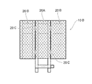
また、本実施形態の作業用足場10Aにおいては、作業板2がその長さ方向に伸縮自在である構成としたが、作業板2の伸縮方向はこれに限らず、例えば、図5に示す作業用足場10Bのように、作業板2の幅方向に伸縮自在である構成としてもよい。
Further, in the
この作業用足場10Bは、図5に示すように、フレーム本体20を、略同一寸法の第1のフレーム本体20Aと、2個の第2のフレーム本体20Bとで構成し、第1のフレーム本体20Aの長さ方向両側面に、第2のフレーム本体20Bをそれぞれ連結部材20Cで連結させた構成となっている。
As shown in FIG. 5, the working
連結部材20Cは、第2のフレーム本体20Bを第1のフレーム本体20Aに対して90°に支持した状態で着脱自在とする切欠き部と、第2のフレーム本体20Bを第1のフレーム本体20Bに対して180°に支持した状態で固定可能とするストッパ部と、を備えたヒンジ部材で構成されている。
The connecting member 20C includes a notch portion that allows the second frame body 20B to be detachable in a state where the second frame body 20B is supported at 90 ° with respect to the
この作業用足場10Bは、作業を行うマンホールMの内径や、作業の種類や作業者の体型等作業状況に応じて、予めマンホールM内部に搬送する前に、第2のフレーム本体20Bを第1のフレーム本体20Aに対して固定して使用する。
The work scaffold 10B is configured such that the second frame main body 20B is first transferred before being transported into the manhole M in advance according to the work conditions such as the inner diameter of the manhole M performing the work, the type of work, and the body shape of the worker. The
本実施形態の作業用足場10Bによれば、作業を行う場所の寸法や作業状況に応じて、作業板2の幅方向の寸法を調整できるため、作業用足場10Bを様々な場所で好適に使用することができるとともに、作業板2の安定性を向上させることができる。
According to the working scaffold 10B of the present embodiment, the width in the width direction of the
なお、本実施形態の作業用足場10Bにおいては、第2のフレーム本体20Bを第1のフレーム本体20Aの両側面に固定した構成としたが、これに限らず、第2のフレーム本体20Bを第1のフレーム本体20Aの一側面に固定するように構成してもよい。
In the working scaffold 10B of the present embodiment, the second frame main body 20B is fixed to both side surfaces of the first frame
また、本実施形態の作業用足場10Bにおいては、第2のフレーム本体20Bを、第1のフレーム本体20Aと略同一寸法で形成したが、これに限らず、第2のフレーム本体20Bの長さ方向の寸法や幅方向の寸法を第1のフレーム本体20Aとは異なる寸法で形成した構成としてもよい。
In the working scaffold 10B of the present embodiment, the second frame main body 20B is formed with substantially the same dimensions as the first frame
さらに、本実施形態の作業用足場10Bにおいては、第2のフレーム本体20Bの第1のフレーム本体20Aへの固定作業を、マンホールMの外部で行うように構成したが、マンホールMの内部でも第2のフレーム本体20Bの固定作業を行えるように、第2のフレーム本体20Bを第1のフレーム本体20Aに対して折り畳み可能な構成としてもよい。この構成にすれば、第2のフレーム本体20Bを使用しない時には、第1のフレーム本体20Aの上面に第2のフレーム本体20Bを折り畳んで収納し、第2のフレーム本体20Bを使用する時には、第2のフレーム本体20Bを第1のフレーム本体20Aの側面に開いて固定した状態で使用することができる。
Furthermore, in the working scaffold 10B of the present embodiment, the second frame main body 20B is fixed to the first frame
<第3実施形態>
図6は、本発明に係る作業用足場の他の構成例を示し、(a)は作業板を閉じた状態を示す側面図、(b)は作業板を開いた状態を示す側面図である。
<Third Embodiment>
FIG. 6 shows another configuration example of the working scaffold according to the present invention, in which (a) is a side view showing a state where the work plate is closed, and (b) is a side view showing a state where the work plate is opened. .
この作業用足場10Cは、図6に示すように、上述した第1実施形態の作業用足場10において、支持フレーム1の上端面をなす鋼柱12に滑車9を備え、この滑車9に支持フレーム1と作業板2の両側面を連結させた状態で吊り下げロープ51を巻き付けた構成となっている。
As shown in FIG. 6, the
次に、本実施形態における作業用足場10Cの一使用例について説明する。
この作業用足場10Cは、まず、一端が支持フレーム1と作業板2とに連結された状態で滑車9に掛け渡された吊り下げ用ロープ51の他端を、マンホールMの外部に設けられた吊り下げフックに引っ掛ける。この時、支持フレーム1と作業板2との間を連結する吊り下げ用ロープ51は、作業板2が支持フレーム1に対して閉じた状態で支持されるように、滑車9に巻き付けられている。
Next, a usage example of the
In this working
次に、図6(a)に示すように、作業板2を支持フレーム1に対して閉じた状態で、作業用足場10BをマンホールМの上部開口部から作業を行う位置まで移動させる。
Next, as shown in FIG. 6A, the
次に、マンホールМ内部の壁面に設けられたステップSの一部にフック3を取り付けて、作業用足場10BをマンホールMの内部に吊設する。
Next, the
次に、図6(b)に示すように、支持フレーム1と作業板2との間を連結する吊り下げ用ロープ51が緩むように、滑車9を回転させて、作業板2を支持フレーム1に対して開いた状態とする。ここで、ステップSの一部にフック3が取り付けられた状態で、支持フレーム1の一面に作業板2が支持フレーム1に対して約90°となるように設置され、支持フレーム1の作業板2の設置面とは反対側に位置する面が複数のステップSと当接した状態で設置される。
Next, as shown in FIG. 6B, the
そして、作業者は、上述した第1実施形態と同様に、支持フレーム1に対して約90°に開かれて設置された作業板2のメッシュ鋼板24の上面に乗り、マンホールМ内部で作業を行う。なお、作業用足場10Bを、別の場所に移動したり、作業終了後にマンホールMから撤去したりする場合には、まず、作業者は作業板2から退き、支持フレーム1と作業板2との間を連結する吊り下げ用ロープ51の滑車9への巻き付け量を多くして、作業板2を支持フレーム1に対して閉じた状態で、作業用足場10Bの移動や撤去を行うようにする。
Then, as in the first embodiment described above, the worker rides on the upper surface of the
本実施形態の作業用足場10Cによれば、支持フレーム1に、支持フレーム1と作業板2とを連結させた吊り下げ用ロープ51を巻き付ける滑車9を設け、この滑車9の回転を制御することで、作業板2を支持フレーム1に対して開閉自在に設置されるようにしたため、作業板2と支持フレーム1との開閉作業の自動化が可能となる。よって、作業用足場10Bの設置や撤去時の作業効率をさらに向上させることができる。
According to the working
また、本実施形態の作業用足場10Cによれば、滑車9の回転を制御して、吊り下げ用ロープ51の巻き付け量を調整することで、作業板2と支持フレーム1との間の開閉角度を容易に変更することができる。
Further, according to the working
<第4実施形態>
図7は、本発明に係る作業用足場の他の構成例を示し、(a)はマンホールの内部壁面に設けられたステップに取り付けた状態を示す側面図、(b)は補助用フックを示す部分拡大平面図である。
<Fourth embodiment>
FIG. 7 shows another configuration example of the working scaffold according to the present invention, wherein (a) is a side view showing a state attached to a step provided on the inner wall surface of the manhole, and (b) shows an auxiliary hook. It is a partial enlarged plan view.
この作業用足場10Dは、図7に示すように、上述した第1実施形態で示した作業用足場10において、支持フレーム1の下端部にさらに補助用フック3aを設けた構成となっている。
As shown in FIG. 7, the working
補助用フック3aは、支持フレーム1の作業板2の設置面とは反対側の面に突出した状態でステップSに取り付け可能となるように、フック取り付け部材31に固定されている。このフック取り付け部材31は、支持フレーム1の両側面に回動自在に固定される平板状の第1部材31Aと、この第1部材31Aに開閉自在に連結され、補助用フック3aが取り付けられる平面視略コ字状の第2部材31Bと、で構成されている。
The
ここで、補助用フック3aは、その周面にねじ溝が設けられており、第2部材31B内部に設けられたねじ溝に螺合可能となっている。この補助用フック3aは、周方向に回転させることで突出長さLが調整自在となっている。
Here, the
また、第2部材31Bの第1部材31Aに対する開閉角度を調整することで、補助用フック3aの第1フレームに対する突出角度が調整自在となっている。
Further, by adjusting the opening / closing angle of the
この作業用足場10Dは、まず、上述した第1実施形態の作業用足場10と同様に、支持フレーム1の上端部に設けたフック3をステップSに取り付ける。次に、支持フレーム1の下端部に設けた補助用フック3aを、その突出長さLや突出角度をステップSの寸法や形状に応じて調整しつつ、ステップSに取り付ける。
In this work scaffold 10D, first, the
本実施形態の作業用足場10Dによれば、支持フレーム1の下端部に補助用フック3aを設け、この補助用フック3aの突出長さLや突出角度を調整自在としたことにより、作業板2の安定性をさらに向上させることができる。
According to the working scaffold 10D of the present embodiment, the
また、本実施形態の作業用足場10Dによれば、補助用フック3aの突出長さLや突出角度を調整自在としたことにより、補助用フック3aの取り付け時の作業効率を向上させることができる。
In addition, according to the working scaffold 10D of the present embodiment, by making the protrusion length L and the protrusion angle of the
なお、本実施形態の作業用足場10Dでは、第1部材31Aを1枚の平板で構成したが、これに限らず、第1部材31Aを一端が開閉自在に連結された2枚の平板で構成し、この第1部材31Aをなす一方の平板を支持フレーム1に固定し、他方の平板を開閉することで、第1部材31Aに対する第2部材31Bの位置が移動するように構成してもよい。この構成にすれば、補助用フック3aをステップSに引っ掛けた後に、第1部材31Aをなす平板のうち、支持フレーム1に固定されていない側の平板を閉じることで、第2部材31BがステップSとは離間する方向に引っ張られるようになるため、補助用フック3aをステップSに強固に固定することができる。
In the working scaffold 10D of the present embodiment, the
1 支持フレーム
2 作業板
3 フック
3a 補助用フック
4 緩衝部材
5A 取り付け金具
5B 車輪
6 ヒンジ部材
7 固定金具
8 工具収納部
9 滑車
10,10A,10B,10C,10D 作業用足場
M マンホール
S ステップ
DESCRIPTION OF
Claims (4)
前記ステップの一部に取り付け可能なフックを有する支持フレームと、この支持フレームの一面に対して回転中心を中心として回動して開閉自在に設置される作業板と、支持フレームと作業板とを連結させた綱材と、この綱材が巻き付けられて前記支持フレームと前記作業板とを閉じた状態にする滑車と、を備え、
前記支持フレームは、補助用フックをさらに備え、前記補助用フックは、前記支持フレームの前記作業板の設置面とは反対側に位置する一面に突出するように設けられ、その突出長さ及びその突出角度の少なくとも一方は調整自在となっており、
前記フック及び補助用フックを前記ステップの一部に取り付けて、前記滑車を回転させて前記綱材が緩むように繰り出すことにより、前記作業板を前記支持フレームに対して所定角度に開いた状態で設置するとともに、前記支持フレームの前記作業板の設置面とは反対側に位置する一面を前記複数のステップに当接させた状態で使用することを特徴とする作業用足場。 A work scaffold used in a place where a plurality of steps are provided on a wall surface,
A support frame having a hook that can be attached to a part of the step, a work plate that is rotated about a rotation center with respect to one surface of the support frame, and that can be opened and closed, and a support frame and a work plate. A coupled rope, and a pulley around which the rope is wound to close the support frame and the work plate,
The support frame further includes an auxiliary hook, and the auxiliary hook is provided so as to protrude on one surface of the support frame opposite to the installation surface of the work plate. At least one of the projecting angles is adjustable,
The work plate is installed at a predetermined angle with respect to the support frame by attaching the hook and the auxiliary hook to a part of the step and rotating the pulley so that the rope is loosened. In addition, the working scaffold is used in a state where one surface of the support frame located on the opposite side to the installation surface of the work plate is in contact with the plurality of steps.
Priority Applications (1)
| Application Number | Priority Date | Filing Date | Title |
|---|---|---|---|
| JP2006158426A JP4505433B2 (en) | 2006-06-07 | 2006-06-07 | Work scaffold |
Applications Claiming Priority (1)
| Application Number | Priority Date | Filing Date | Title |
|---|---|---|---|
| JP2006158426A JP4505433B2 (en) | 2006-06-07 | 2006-06-07 | Work scaffold |
Publications (3)
| Publication Number | Publication Date |
|---|---|
| JP2007327221A JP2007327221A (en) | 2007-12-20 |
| JP2007327221A5 JP2007327221A5 (en) | 2009-07-23 |
| JP4505433B2 true JP4505433B2 (en) | 2010-07-21 |
Family
ID=38927868
Family Applications (1)
| Application Number | Title | Priority Date | Filing Date |
|---|---|---|---|
| JP2006158426A Expired - Fee Related JP4505433B2 (en) | 2006-06-07 | 2006-06-07 | Work scaffold |
Country Status (1)
| Country | Link |
|---|---|
| JP (1) | JP4505433B2 (en) |
Families Citing this family (4)
| Publication number | Priority date | Publication date | Assignee | Title |
|---|---|---|---|---|
| JP2009270317A (en) * | 2008-05-07 | 2009-11-19 | Ito Kiko Kk | Scaffold base, scaffold for simple work, and method of manufacturing the same |
| CN106639288B (en) * | 2016-11-16 | 2023-02-28 | 上海市建筑装饰工程集团有限公司 | Method for installing and using vertical transport platform for stone in outer wall scaffold |
| MX2021007206A (en) * | 2018-12-17 | 2021-12-15 | Terex South Dakota Inc | Access deck assembly and handle assembly for an aerial work platform of a vehicle. |
| KR102598010B1 (en) * | 2022-07-07 | 2023-11-02 | 김윤회 | scaffold for ladder of manhole |
Citations (4)
| Publication number | Priority date | Publication date | Assignee | Title |
|---|---|---|---|---|
| JPH0317481U (en) * | 1989-06-30 | 1991-02-21 | ||
| JP2000257094A (en) * | 1999-03-05 | 2000-09-19 | Miyama Ind Corp | Intermediate foot step for maintenance |
| JP2001097479A (en) * | 1999-09-24 | 2001-04-10 | Yokota Kogyo Kk | Working table device for ceiling or the like of silo |
| JP2006046057A (en) * | 2004-07-08 | 2006-02-16 | Masaru Kotake | Simplified working scaffold |
Family Cites Families (2)
| Publication number | Priority date | Publication date | Assignee | Title |
|---|---|---|---|---|
| JP2765794B2 (en) * | 1993-04-23 | 1998-06-18 | 積水化学工業株式会社 | Ladder-mounted workbench |
| JP2803986B2 (en) * | 1993-11-18 | 1998-09-24 | 積水化学工業株式会社 | Wall work bench |
-
2006
- 2006-06-07 JP JP2006158426A patent/JP4505433B2/en not_active Expired - Fee Related
Patent Citations (4)
| Publication number | Priority date | Publication date | Assignee | Title |
|---|---|---|---|---|
| JPH0317481U (en) * | 1989-06-30 | 1991-02-21 | ||
| JP2000257094A (en) * | 1999-03-05 | 2000-09-19 | Miyama Ind Corp | Intermediate foot step for maintenance |
| JP2001097479A (en) * | 1999-09-24 | 2001-04-10 | Yokota Kogyo Kk | Working table device for ceiling or the like of silo |
| JP2006046057A (en) * | 2004-07-08 | 2006-02-16 | Masaru Kotake | Simplified working scaffold |
Also Published As
| Publication number | Publication date |
|---|---|
| JP2007327221A (en) | 2007-12-20 |
Similar Documents
| Publication | Publication Date | Title |
|---|---|---|
| JP4505433B2 (en) | Work scaffold | |
| JP2006282287A (en) | Positioning guide and positioning method when installing boom of self-travelling crane | |
| JP2015212184A (en) | Clamping device for suspending tabular housing materials | |
| KR102264497B1 (en) | Opening and closing apparatus for manhole cover | |
| JP5731311B2 (en) | Concrete block lifting jig | |
| JP2006193235A (en) | Hoisting device | |
| JP5232479B2 (en) | Slide scaffolding equipment | |
| US7080823B1 (en) | Engine hoist mounting a transmission adapter | |
| JP5279547B2 (en) | Installation tool for overhead wire damper | |
| JP7464426B2 (en) | Lifting jig and construction method using the lifting jig | |
| JP6080788B2 (en) | Bracket scaffolding tread | |
| JP2016199997A (en) | Simple crane | |
| JP2017186131A (en) | Crane device and curtain wall installation method | |
| KR102357547B1 (en) | Opening and closing apparatus of manhole cover for easy storage and movement | |
| JP2018115057A (en) | Opening/closing device building material lifting auxiliary tool, lifting device, and building material lifting method using the lifting device | |
| KR101007963B1 (en) | Aerial working platform with materials support means | |
| JP6748438B2 (en) | Lifting device | |
| JP2008115683A (en) | Temporary guide device for wall surface work and setting method thereof | |
| JP2643212B2 (en) | Hanging beam for crane | |
| CN209778151U (en) | Lifting appliance for lifting curtain wall plates | |
| JP7493979B2 (en) | Hanging balance and construction method using the hanging balance | |
| JP5123757B2 (en) | Bracket for mounting safety net | |
| JP6624768B1 (en) | Vehicle | |
| JP2006193257A (en) | Elevator rope holding device, and installing method thereof | |
| JP3274124B2 (en) | Jig for hanging a chain block |
Legal Events
| Date | Code | Title | Description |
|---|---|---|---|
| A871 | Explanation of circumstances concerning accelerated examination |
Free format text: JAPANESE INTERMEDIATE CODE: A871 Effective date: 20090519 |
|
| A521 | Written amendment |
Free format text: JAPANESE INTERMEDIATE CODE: A523 Effective date: 20090501 |
|
| A621 | Written request for application examination |
Free format text: JAPANESE INTERMEDIATE CODE: A621 Effective date: 20090511 |
|
| A975 | Report on accelerated examination |
Free format text: JAPANESE INTERMEDIATE CODE: A971005 Effective date: 20090624 |
|
| RD04 | Notification of resignation of power of attorney |
Free format text: JAPANESE INTERMEDIATE CODE: A7424 Effective date: 20090616 |
|
| A131 | Notification of reasons for refusal |
Free format text: JAPANESE INTERMEDIATE CODE: A131 Effective date: 20090804 |
|
| A521 | Written amendment |
Free format text: JAPANESE INTERMEDIATE CODE: A523 Effective date: 20090916 |
|
| RD02 | Notification of acceptance of power of attorney |
Free format text: JAPANESE INTERMEDIATE CODE: A7422 Effective date: 20090916 |
|
| A131 | Notification of reasons for refusal |
Free format text: JAPANESE INTERMEDIATE CODE: A131 Effective date: 20091208 |
|
| A521 | Written amendment |
Free format text: JAPANESE INTERMEDIATE CODE: A523 Effective date: 20100205 |
|
| TRDD | Decision of grant or rejection written | ||
| A01 | Written decision to grant a patent or to grant a registration (utility model) |
Free format text: JAPANESE INTERMEDIATE CODE: A01 Effective date: 20100420 |
|
| A01 | Written decision to grant a patent or to grant a registration (utility model) |
Free format text: JAPANESE INTERMEDIATE CODE: A01 |
|
| A61 | First payment of annual fees (during grant procedure) |
Free format text: JAPANESE INTERMEDIATE CODE: A61 Effective date: 20100426 |
|
| R150 | Certificate of patent or registration of utility model |
Ref document number: 4505433 Country of ref document: JP Free format text: JAPANESE INTERMEDIATE CODE: R150 Free format text: JAPANESE INTERMEDIATE CODE: R150 |
|
| FPAY | Renewal fee payment (event date is renewal date of database) |
Free format text: PAYMENT UNTIL: 20190430 Year of fee payment: 9 |
|
| R250 | Receipt of annual fees |
Free format text: JAPANESE INTERMEDIATE CODE: R250 |
|
| R250 | Receipt of annual fees |
Free format text: JAPANESE INTERMEDIATE CODE: R250 |
|
| LAPS | Cancellation because of no payment of annual fees |