JP2006192638A - Inkjet recording apparatus - Google Patents
Inkjet recording apparatus Download PDFInfo
- Publication number
- JP2006192638A JP2006192638A JP2005004965A JP2005004965A JP2006192638A JP 2006192638 A JP2006192638 A JP 2006192638A JP 2005004965 A JP2005004965 A JP 2005004965A JP 2005004965 A JP2005004965 A JP 2005004965A JP 2006192638 A JP2006192638 A JP 2006192638A
- Authority
- JP
- Japan
- Prior art keywords
- ink
- tank
- filter
- supply
- head
- Prior art date
- Legal status (The legal status is an assumption and is not a legal conclusion. Google has not performed a legal analysis and makes no representation as to the accuracy of the status listed.)
- Pending
Links
Images


Classifications
-
- B—PERFORMING OPERATIONS; TRANSPORTING
- B41—PRINTING; LINING MACHINES; TYPEWRITERS; STAMPS
- B41J—TYPEWRITERS; SELECTIVE PRINTING MECHANISMS, i.e. MECHANISMS PRINTING OTHERWISE THAN FROM A FORME; CORRECTION OF TYPOGRAPHICAL ERRORS
- B41J2/00—Typewriters or selective printing mechanisms characterised by the printing or marking process for which they are designed
- B41J2/005—Typewriters or selective printing mechanisms characterised by the printing or marking process for which they are designed characterised by bringing liquid or particles selectively into contact with a printing material
- B41J2/01—Ink jet
- B41J2/17—Ink jet characterised by ink handling
- B41J2/18—Ink recirculation systems
Abstract
Description
本発明は、記録媒体に向けてインクを吐出させて記録を行うインクジェット記録装置に関し、より具体的には、静圧方式で吐出ヘッドにインクを供給し、吐出ヘッドからインクを吐出させて記録を行うインクジェット記録装置に関する。 The present invention relates to an ink jet recording apparatus that performs recording by discharging ink toward a recording medium, and more specifically, supplies ink to a discharge head by a static pressure method, and discharges ink from the discharge head to perform recording. The present invention relates to an inkjet recording apparatus.
記録媒体に向けてインクを吐出させて記録を行うインクジェット記録装置としては、例えば、インクに静電力を作用させてインク液滴を吐出する静電式のインクジェット記録方式がある。この静電式インクジェット記録方式の1つとしては、色材および樹脂を含み、かつ、荷電した微粒子成分(以下、色材粒子とする)を絶縁性のキャリア液(分散媒)に分散してなるインクを用い、画像データに応じてインクジェットヘッドの吐出電極に電圧(駆動電圧)を印加してインクに静電力を作用させることにより、インクの吐出を制御して、オンデマンドで記録媒体に画像を記録する方式により記録を行うインクジェット記録装置が知られている。 As an inkjet recording apparatus that performs recording by ejecting ink toward a recording medium, for example, there is an electrostatic inkjet recording system that ejects ink droplets by applying an electrostatic force to ink. As one of the electrostatic ink jet recording methods, a coloring material and a resin are included, and charged fine particle components (hereinafter referred to as coloring material particles) are dispersed in an insulating carrier liquid (dispersion medium). By using ink and applying a voltage (driving voltage) to the ejection electrode of the inkjet head according to the image data to cause the electrostatic force to act on the ink, the ejection of the ink is controlled, and the image is recorded on the recording medium on demand. 2. Related Art Inkjet recording apparatuses that perform recording by a recording method are known.
色材粒子を有するインクを用いる静電式のインクジェット記録では、例えば、記録媒体にバイアス電圧を帯電させた上でインクジェットヘッドに対面させた状態で、インクの各吐出部に対応して形成された吐出電極に駆動電圧を印加することにより、吐出部(および吐出部近傍)のインクに静電力を作用させる。
この静電力の作用により、色材粒子が泳動して吐出部に集まり(すなわち、吐出部でインクが濃縮され)、インク液滴として吐出される。
In electrostatic ink jet recording using ink having colorant particles, for example, a bias voltage is charged on a recording medium, and the ink jet recording head is formed corresponding to each ink ejection portion in a state of facing the ink jet head. By applying a driving voltage to the ejection electrode, an electrostatic force is applied to the ink in the ejection section (and the vicinity of the ejection section).
Due to the action of the electrostatic force, the color material particles migrate and gather in the ejection part (that is, the ink is concentrated in the ejection part), and are ejected as ink droplets.
このような静電式インクジェットにおいて、各吐出部にインクを供給する方法の一例として、インクを貯留するタンクからインクジェットヘッドにインクを供給し、インクジェットヘッド内において各吐出部と連通する所定のインク流路にインクを流し、吐出されずにインク流路を通過したインクをインクジェットから前記タンクに戻す、所定の循環経路でインクを循環する方法が例示される。 In such an electrostatic ink jet, as an example of a method of supplying ink to each ejection unit, ink is supplied from a tank that stores ink to the inkjet head, and a predetermined ink flow that communicates with each ejection unit in the inkjet head. An example is a method in which ink is circulated through a predetermined circulation path in which ink is passed through the path and ink that has passed through the ink flow path without being discharged is returned from the inkjet to the tank.
例えば、特許文献1には、図6に示されるように、色材粒子を有するインクを静電式のインクジェットヘッド(以下、記録ヘッドとする)200から吐出して、記録媒体Pに画像を記録するインクジェット記録装置において、インクを貯留するタンク202からポンプ204によってタンク206にインクを供給し、タンク206から水頭圧をかけつつ重力落下で記録ヘッド200にインクを供給すると共に、記録ヘッド200から吐出されなかったインクをタンク202に戻す循環系を有するインクジェット記録装置が開示されている。また、このインクジェット記録装置は、劣化したインクを廃棄するタンク210、および新規(未使用)インクを貯留するタンク214を有する。
また、このインクジェット記録装置では、循環しているインクの劣化状態を検出し、その結果に応じて、ポンプ204を停止してタンク206のインクを全てタンク202に回収し、次いで、バルブ208を開いて劣化したインクをタンク210にインクを廃棄し、タンク202が空になったら、バルブ212を開いてタンク214から新規インクをタンク202に供給して、再度、循環を行う。
For example, in Patent Document 1, as shown in FIG. 6, an ink having colorant particles is ejected from an electrostatic inkjet head (hereinafter referred to as a recording head) 200 to record an image on a recording medium P. In the ink jet recording apparatus, the ink is supplied from the
In this ink jet recording apparatus, the deterioration state of the circulating ink is detected, and according to the result, the pump 204 is stopped to collect all the ink in the
ここで、特許文献1に開示のインクジェット記録装置は、記録ヘッド(吐出ヘッド)200にインクを供給するタンク206から水頭圧をかけつつ重力落下で記録ヘッド200にインクを供給することで、記録ヘッドに一定圧でインクを供給することができるが、タンク206の内壁面で凝集固形物が形成される可能性、タンク206内のインクが空気と触れるため、気液界面でのインクの蒸発による凝集固形物等の発生の可能性、また、タンク206へゴミが混入する可能性等がある。
このようなゴミや凝集固形物等の異物がインクに混入し、そのインクが記録ヘッド200に供給されると、異物により記録ヘッドの吐出口(ノズル)に目詰まりが発生し、インク液滴の吐出が不可能になることがある。
Here, the ink jet recording apparatus disclosed in Patent Document 1 supplies the
When foreign matter such as dust or agglomerated solids enters the ink and the ink is supplied to the
これに対して、本発明者は、このような静圧方式により、記録ヘッドにインクの供給を行うサブタンクを用いるインクジェット記録装置において、記録ヘッドとサブタンクとの間に異物を除去するフィルタを設けることで、記録ヘッドにインクを供給するタンク内で発生した異物も除去することができ、記録ヘッドでも目詰まりを防止できることを見出した。 On the other hand, the present inventor provides a filter for removing foreign matter between the recording head and the sub tank in the ink jet recording apparatus using the sub tank that supplies ink to the recording head by such a static pressure method. Thus, the present inventors have found that foreign matter generated in a tank that supplies ink to the recording head can be removed, and the recording head can also be prevented from being clogged.
しかしながら、記録ヘッドとサブタンクとの間にフィルタを設けることで、記録ヘッドへの異物の混入は防止できるが、インクジェット記録装置を使用した後に、一旦使用を停止し、インクジェットヘッド等のインク循環系から、インクを抜き取り、メインタンク等に戻した後も、フィルタにインクが残っていると、記録ヘッドにかかる静圧によっては、フィルタ内のインクの表面張力等により、記録ヘッドへのインク供給開始時(循環開始時)にインクがフィルタを通液できず、フィルタでインクの通液が止まることがあった。このようにフィルタでインクの通液が止まると、記録ヘッドにインクが供給できず、画像記録を行うことができなくなり、問題である。 However, by providing a filter between the recording head and the sub tank, foreign matter can be prevented from entering the recording head. However, after using the ink jet recording apparatus, the use is temporarily stopped and the ink circulation system such as the ink jet head is used. If the ink remains in the filter even after it has been extracted and returned to the main tank, etc., depending on the static pressure applied to the recording head, the surface tension of the ink in the filter may cause the ink supply to the recording head. Ink may not pass through the filter (when circulation starts), and ink may stop passing through the filter. Thus, if the ink flow is stopped by the filter, the ink cannot be supplied to the recording head and image recording cannot be performed, which is a problem.
本発明の目的は、上記課題を解決し、静圧方式により記録ヘッド(インクジェットヘッド)にインクの供給を行うサブタンクを有するインクジェット記録装置であり、そのインクジェットヘッドとサブタンクとの間にフィルタを設けた場合でも、インクジェットヘッドへのインク供給開始時に、フィルタでインクの供給が止まることなく、インクジェットヘッドにインクを供給することができ、かつ、簡単な装置構成のインクジェット記録装置を提供することにある。 An object of the present invention is an ink jet recording apparatus having a sub tank that solves the above problems and supplies ink to a recording head (ink jet head) by a static pressure method, and a filter is provided between the ink jet head and the sub tank. Even in such a case, it is an object of the present invention to provide an ink jet recording apparatus having a simple device configuration that can supply ink to the ink jet head without stopping the ink supply by the filter at the start of ink supply to the ink jet head.
上記課題を解決するために、本発明は、インクを吐出するためのインクジェットヘッドを有するインクジェット記録装置であって、前記インクを貯留するメインタンクと、前記メインタンクから供給されるインクを貯留し、前記インクジェットヘッドに静圧方式によりインクの供給を行う供給用サブタンクと、前記メインタンクから前記供給用サブタンクに接続される第1の供給配管を含み、前記メインタンク、前記供給用サブタンクおよび前記インクジェットヘッドとの間でインクを循環させるインク循環系と、前記インク循環系の前記供給用サブタンクと前記インクジェットヘッドとの間において、前記供給用サブタンクのインクの循環時における気液界面よりも前記インクジェットヘッド側に設置されたフィルタとを有し、前記フィルタの前記インクジェットヘッド側および気液界面側のいずれか一方の面に前記第1の供給配管の液流の少なくとも一部を直接的に吐出させることを特徴とするインクジェット記録装置を提供する。 In order to solve the above problems, the present invention is an ink jet recording apparatus having an ink jet head for discharging ink, the main tank storing the ink, the ink supplied from the main tank, A sub tank for supplying ink to the ink jet head by a static pressure method; and a first supply pipe connected from the main tank to the sub tank for supply; the main tank, the sub tank for supply, and the ink jet head An ink circulation system that circulates ink between the ink supply head and the supply subtank of the ink circulation system and the ink jet head. And a filter installed on the filter. It said to provide an ink-jet recording apparatus for causing at least a portion of the ink jet head side and the gas-liquid interface side of the first supply pipe liquid flow either to one surface of the directly discharged in.
ここで、前記インク循環系は、さらに、前記供給用サブタンクから前記インクジェットヘッドに接続される第2の供給配管を含み、前記フィルタは、前記供給用サブタンクと前記第2の供給配管との間に挿設されることが好ましい。
また、前記インクとして、少なくとも樹脂および色材を含有する微粒子を溶媒に分散してなるインクを用いることが好ましい。
Here, the ink circulation system further includes a second supply pipe connected from the supply sub tank to the inkjet head, and the filter is interposed between the supply sub tank and the second supply pipe. It is preferable to be inserted.
Moreover, it is preferable to use an ink in which fine particles containing at least a resin and a color material are dispersed in a solvent as the ink.
さらに、前記第1の供給配管から分岐し、前記フィルタの前記インクジェットヘッド側の面に前記フィルタに前記第1の供給配管から供給されるインクの液流を直接的に吐出させる分岐配管を有することが好ましい。
また、前記供給用サブタンクは、前記フィルタ近傍に開口された前記第1の供給配管との接続口を有し、前記接続口から吐出されるインクの液流を前記フィルタの前記気液界面側の面に直接的に吐出させることが好ましい。
And a branch pipe that branches from the first supply pipe and that directly discharges a liquid flow of ink supplied from the first supply pipe to the filter on a surface of the filter on the ink jet head side. Is preferred.
Further, the supply sub-tank has a connection port with the first supply pipe opened near the filter, and the liquid flow of the ink discharged from the connection port is on the gas-liquid interface side of the filter. It is preferable to discharge directly to the surface.
また、前記フィルタは、第1のフィルタであり、さらに、前記インク循環系の前記インクタンクと前記供給用サブタンクとの間に、第2のフィルタが設置されることが好ましい。
さらに、前記第1の供給配管を介して前記インクタンクから前記供給用サブタンクにインクを送液する送液手段を有し、前記送液手段は、前記第2のフィルタを通過したインクを前記供給用サブタンクに送液することが好ましい。
The filter may be a first filter, and a second filter may be provided between the ink tank and the supply sub tank of the ink circulation system.
Furthermore, the liquid supply means has a liquid supply means for supplying ink from the ink tank to the supply subtank via the first supply pipe, and the liquid supply means supplies the ink that has passed through the second filter to the supply. It is preferable that the liquid is sent to the sub tank.
また、前記供給用サブタンクは、前記インクジェットヘッドよりも高い位置に配置され、オーバーフローによって、インク液面の高さを一定に保ちつつ、前記インクジェットヘッドにインクを供給することが好ましい。
さらに、前記インクジェットヘッドからインクを回収する回収用サブタンクを有し、前記回収用サブタンクは、前記インクジェットヘッドよりも低い位置に配置され、オーバーフローによって、インク液面の高さを一定に保ちつつ、前記インクジェットヘッドからインクを回収することが好ましい。
ここで、前記サブタンクは、最下位置に前記供給配管との接続口を備え、インクの循環の停止時に、前記サブタンクに貯留されているインクは、前記供給配管を通じて前記インクタンクに回収されることが好ましい。
The supply sub-tank is preferably disposed at a position higher than the inkjet head, and supplies ink to the inkjet head while maintaining a constant ink liquid level by overflow.
And a recovery sub-tank for recovering ink from the inkjet head, the recovery sub-tank being disposed at a position lower than the inkjet head, while maintaining a constant ink liquid level by overflow, It is preferable to collect ink from the inkjet head.
Here, the sub tank includes a connection port with the supply pipe at the lowest position, and when the ink circulation is stopped, the ink stored in the sub tank is collected into the ink tank through the supply pipe. Is preferred.
さらに、前記インクジェットヘッドに装着され、前記吐出ヘッドのインク吐出部に蓋をするキャッピング手段と、前記サブタンクの少なくとも1つと前記キャッピング手段および前記インクジェットヘッドの少なくとも一方とを接続する連通配管とを有し、前記連通配管は、前記キャッピング手段および前記インクジェットヘッドのキャッピング面に形成された、前記少なくとも1つのインクタンクの空気を外気と連通させる連通口を備え、前記キャッピング手段を前記インクジェットヘッドに装着して、前記連通配管による外気への連通を断ち、前記キャッピング手段を前記インクジェットヘッドから離脱させて、前記連通配管による外気への連通を行うことが好ましい。
さらに、高濃度インクを前記メインタンクに補充する高濃度インク補充部と、希釈液を前記メインタンクに補充する希釈液補充部とを少なくとも備えるインク補充手段を有することが好ましい。
また、前記希釈液補充タンクは、さらに前記サブタンクおよび前記インクジェットヘッドに希釈液を循環させる循環系と接続されていることが好ましい。
And capping means attached to the ink jet head for covering the ink ejection portion of the ejection head, and communication piping for connecting at least one of the sub tank and at least one of the capping means and the ink jet head. The communication pipe includes a communication port formed on the capping surface of the capping unit and the inkjet head for communicating the air of the at least one ink tank with the outside air, and the capping unit is attached to the inkjet head. Preferably, the communication pipe is disconnected from the outside air, the capping means is detached from the inkjet head, and the communication pipe communicates with the outside air.
Furthermore, it is preferable to have an ink replenishing unit including at least a high concentration ink replenishing unit that replenishes the main tank with high concentration ink and a diluent replenishing unit that replenishes the main tank with a diluent.
The diluent replenishing tank is preferably connected to a circulation system for circulating the diluent to the sub tank and the inkjet head.
本発明によれば、静圧方式により記録ヘッド(インクジェットヘッド)にインクの供給を行うサブタンクを有するインクジェット記録装置であり、そのインクジェットヘッドとサブタンクとの間にフィルタを設けた場合でも、インク供給開始時(インク循環開始時)に、フィルタでインクの通液が止まることを防止でき、フィルタを通過し、異物が除去されたインクを好適に吐出ヘッドに供給することができ、
インクジェットヘッドの吐出部が異物により目詰まりすることを防止できる。
さらに、本発明によれば、簡単な装置構成とすることができるので、装置コストも低くすることができる。
According to the present invention, an ink jet recording apparatus having a sub tank that supplies ink to a recording head (ink jet head) by a static pressure method, and ink supply starts even when a filter is provided between the ink jet head and the sub tank. At the time (when ink circulation starts), it is possible to prevent the ink from passing through the filter, and the ink that has passed through the filter and from which foreign matter has been removed can be suitably supplied to the ejection head.
It is possible to prevent the ejection part of the inkjet head from being clogged with foreign matter.
Furthermore, according to the present invention, since a simple device configuration can be achieved, the device cost can be reduced.
以下、本発明のインクジェット記録装置について、添付の図面に示される好適実施例を基に、詳細に説明する。 Hereinafter, the ink jet recording apparatus of the present invention will be described in detail based on a preferred embodiment shown in the accompanying drawings.
図1に、本発明のインクジェット記録装置の一例を概念的に示す。
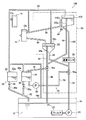
図1に示したインクジェット記録装置(以下、記録装置10という)10は、色材および樹脂を含む帯電した微粒子(以下、色材粒子とする)を絶縁性のキャリア液(分散媒)に分散してなるインクQを用い、このインクに静電力を作用させることによりインク液滴を吐出する静電式のインクジェット記録装置である。記録装置10は、図1に示すように、基本的に、吐出ヘッド(インクジェットヘッド)12と、メインタンク16と、インク補充手段22と、インク循環ポンプ25と、異物除去手段26と、インク循環経路30と、洗浄手段53と、連通配管59と、キャッピンク部材60とを有する。
FIG. 1 conceptually shows an example of the ink jet recording apparatus of the present invention.
An ink jet recording apparatus (hereinafter referred to as a recording apparatus 10) 10 shown in FIG. 1 disperses charged fine particles (hereinafter referred to as color material particles) containing a color material and a resin in an insulating carrier liquid (dispersion medium). And an electrostatic ink jet recording apparatus that ejects ink droplets by applying an electrostatic force to the ink. As shown in FIG. 1, the
記録装置10のインク循環経路30は、主に、メインタンク16のインクQを吐出ヘッド12に供給するインク供給経路と、吐出ヘッド12から吐出されなかったインクQを回収するインク回収経路とから構成される。インク供給経路は、供給サブタンク18、インク循環ポンプ25に接続された共通供給配管32、共通供給配管32と供給サブタンク18とを接続する第1供給配管34、共通供給配管32と回収サブタンク20とを接続する第3供給配管38、供給サブタンク18と吐出ヘッド12とを接続する第2供給配管36、および、供給サブタンク18内のオーバーフロー管18aからオーバーフローしたインクQを回収する第3回収配管44から主に構成される。また、インク回収経路は、回収サブタンク20、吐出ヘッド12と回収サブタンク20とを接続する第1回収配管40、回収サブタンク20内のオーバーフロー管20aからオーバーフローしたインクを回収する第2回収配管42、第2回収配管42および第3回収配管44によって回収したインクをメインタンク16に回収する共通回収配管46から主に構成される。供給配管や回収配管は、例えば、パイプや可撓性を有するチューブなどから構成することができる。
The
なお、図1は、本発明の特徴的な部位を主に示しているが、本発明の記録装置10は、図に示したインク循環系以外にも、例えば、吐出ヘッド12を駆動してインク液滴を吐出させるドライバ、吐出ヘッド12と対面する所定の経路で、後述する吐出口列方向(行方向)と直交する方向に記録媒体Pを搬送(走査搬送)する走査搬送手段、吐出ヘッド12による画像記録に先立って記録媒体Pに所定のバイアス電圧を帯電させる帯電手段(あるいは吐出ヘッド12の制御電極に対する対向電極)、帯電した記録媒体Pを除電する除電手段、所定の経路で記録媒体Pを搬送する搬送手段、搬送される記録媒体Pを検出するセンサ、装置内に滞留するキャリア液等を排出する溶媒排出手段など、公知の静電式のインクジェット記録装置が有する各種の構成要素を有しているのは、もちろんのことである。
FIG. 1 mainly shows the characteristic portions of the present invention. However, the
また、本発明のインクジェット記録装置は、K(黒)のみなどの1色の画像記録を行うモノクロの記録装置であってもよく、また、Y(イエロー)、M(マゼンタ)、C(シアン)、およびKの4色のインクを用いて、記録媒体にフルカラー画像を描画する記録装置であってもよい。
また、吐出ヘッドは静電式のインクジェットヘッドに限定されず、サーマルインクジェットヘッド、ピエゾ素子やマイクロマシン等によってインク室の振動板振動することによりインクを吐出するタイプのインクジェットヘッド等、各種のインクジェットヘッドを好適に利用可能である。
In addition, the inkjet recording apparatus of the present invention may be a monochrome recording apparatus that records an image of one color such as K (black) alone, and Y (yellow), M (magenta), C (cyan). And a recording apparatus that draws a full-color image on a recording medium using four colors of inks K and K.
The ejection head is not limited to an electrostatic inkjet head, and various inkjet heads such as a thermal inkjet head, an inkjet head that ejects ink by vibrating a diaphragm of an ink chamber by a piezo element, a micromachine, or the like can be used. It can be suitably used.
メインタンク16は、記録装置10のインク循環経路30を循環するインクを主に貯留するための密閉型のインクタンクである。
メインタンク16内部には、インク循環経路30にインクを循環させるインク循環ポンプ25と、異物除去手段26のフィルタ27とが配置されている。フィルタ27は、インク循環ポンプ25に接続されている。フィルタ27については後ほど詳述する。
The
Inside the
インク循環ポンプ25は、一端はフィルタ27と接続し、他端が共通供給配管32と接続している。インク循環ポンプ25は、フィルタ27を介してメインタンク16内のインクを吸引し、共通供給配管32に供給する。インク循環ポンプ25は、稼動時にインクを共通供給配管32に供給し、停止時は、共通供給配管32内のインクを保持することなく重力に応じて、メインタンク16内にインクが回収される非自給式ポンプである。ここで、非自給式ポンプとしては、渦巻きポンプやディフューザポンプ等の遠心ポンプ、軸流ポンプ、斜流ポンプが例示される。また、インク粒子の凝集固着を起こす原因となるポンプ内部の液接部分の回転摺動部が無い点から、インク循環ポンプ25は、渦巻きポンプを用いることが好ましい。
メインタンク16は、さらに、色材粒子の沈降/堆積を防止するための撹拌手段や、インク吐出の安定性を向上するための温度調節手段を有するのが好ましい。
The
The
上述したように、図1に示した記録装置10は、供給サブタンク18、および回収サブタンク20、ならびに、これらを接続する各配管で構成されるインク循環経路30を有し、このインク循環経路30によってメインタンク16に貯留されているインクQを循環することにより、吐出ヘッド12にインクを供給する静圧式のインクジェット記録装置である。
As described above, the
共通供給配管32は、一端がインク循環ポンプ25と接続され、他端は、第1供給配管34および第3供給配管38と接続されている。これにより、インク循環ポンプ25から共通供給配管32に供給されたインクは、第1供給配管34と第3供給配管38とに供給される。
One end of the
供給サブタンク18は、第1供給配管34および第2供給配管36が接続される密閉型のインクタンクであり、鉛直方向において吐出ヘッド12よりも上方に配置される。ここで、供給サブタンク18と第2供給配管36とは、フィルタ29、空隙39を介して接続されている。フィルタ29、空隙39については、後ほど詳細に説明する。また、供給サブタンク18に接続された第2供給配管36の他端は、吐出ヘッド12に接続されている。
この供給サブタンク18は、下面が開放する中空の四角柱の下に、上部(底面)が開放する中空の逆四角錐を設けた形状を有するものである。従って、供給サブタンク18の底面(床面)は、水平部分を有さず、全面が一点(最低部)に向かって傾斜している。この最低部には開口が形成され、開口部は第1供給配管34と接続している。
供給サブタンク18には、共通供給配管32および第1供給配管34を介してメインタンク16から供給されたインクQが貯留され、貯留されたインクQは第2供給配管36を介して吐出ヘッド12に供給される。
The
The
The
また、供給サブタンク18内には、第3回収配管44に接続するオーバーフロー管18aが配置され、かつ、第2供給配管36はオーバーフロー管18aの上端よりも下方に接続される。図示例では、第2供給配管36との接続部を供給サブタンク18の底面に設けた構成としている。
Further, an overflow pipe 18a connected to the
供給サブタンク18に貯留されたインクは、供給サブタンク18と吐出ヘッド12(又は回収サブタンク20)の高低差(落差)に応じた圧力で、重力落下によって第2供給配管36から吐出ヘッド12に供給される。
また、供給サブタンク18では、インク循環ポンプ25により供給されたインクがオーバーフロー管18aの高さを超えても、オーバーフロー管18aからオーバーフローして排出されるので、タンク内の液面の高さは一定に保たれる。その結果、供給サブタンク18から吐出ヘッド12へのインクQの供給量および供給圧(圧力ヘッド)は一定に保たれ、いわゆる静圧系でのインク供給が行われる。
なお、オーバーフロー管18aから排出されたインクQは、第3回収配管44および共通回収配管46、メインタンク16に戻され、再度、循環に供される。
The ink stored in the
Further, in the
The ink Q discharged from the overflow pipe 18a is returned to the
回収サブタンク20は、第1回収配管40、第2回収配管42および第3供給配管38が接続される密閉型のインクタンクであり、吐出ヘッド12よりも鉛直方向において下方に配置される。この回収サブタンク20は、下面が開放する中空の四角柱の下に、上部(底面)が開放する中空の逆四角錐を設けた形状を有するものである。従って、回収サブタンク20の底面(床面)は、水平部分を有さず、全面が一点(最低部)に向かって傾斜している。この最低部には開口が形成され、開口部は第3供給配管38と接続している。
前述のように、第1回収配管40の他端は吐出ヘッド12に、第2回収配管42の他端は共通回収配管46に、それぞれ接続される。
回収サブタンク20には、メインタンク16のインクが第3供給配管38を通じて供給され、吐出ヘッド12から吐出されなかったインクQが第1回収配管40を通じて貯留される。回収サブタンク20に貯留されたインクQは第2回収配管42および共通回収配管46を通じてメインタンク16に戻される。
The
As described above, the other end of the
Ink in the
ここで、吐出ヘッド12から吐出されずに吐出ヘッド12から排出されたインクQは、吐出ヘッド12(又は供給サブタンク18)と回収サブタンク20との高低差(落差)に応じた圧力で、重力落下によって第1回収配管40から回収サブタンク20に供給される。回収サブタンク20において、オーバーフロー管20aを超えたインクQは、第2回収配管42を通ってメインタンク16に戻されて、再度、循環に供される。
また、回収サブタンク20のインク液面は、オーバーフロー管20aによって一定に保たれる。これにより、吐出ヘッド12からのインク流入にも、回収サブタンク20の液面の高さに応じた一定の圧量(圧力ヘッド)がかかる。すなわち、吐出ヘッド12に、一定の静圧をかけることができる。
Here, the ink Q discharged from the
Further, the ink liquid level in the
記録装置10においては、このように、供給サブタンク18に貯留されているインクの一定の圧力ヘッドで供給サブタンク18から吐出ヘッド12へインク供給するとともに、吐出ヘッド12から回収サブタンク20へのインク供給にも一定の圧力をかける。これにより、吐出ヘッド12の内部に形成されたインク流路に係る圧力、すなわち吐出ヘッド12へのインク供給および排出を完全に静圧にすることができ、後述する吐出ヘッド12の吐出口に形成されるインクQのメニスカス等を安定させることができる。
In the
本実施形態の記録装置10においては、供給サブタンク18および/または回収サブタンク20の高さを、適宜、設定することにより、吐出ヘッドの吐出口に形成されるインクQのメニスカスの高さを、高い自由度で選択することも可能である。従って、前記メニスカスの状態や高さをコントロール可能にするために、供給サブタンク18および/または回収サブタンク20の高さを調節するための高さ調節手段を有することが好ましい。
なお、高さ調節手段は、互いに螺合するネジ軸とナットによる方法、シリンダやアクチュエータを用いる方法、カムを用いる方法等、鉛直方向の高さ調整が可能な各種の方法が利用可能である。
In the
As the height adjusting means, various methods capable of adjusting the height in the vertical direction, such as a method using a screw shaft and a nut that are screwed together, a method using a cylinder or an actuator, and a method using a cam can be used.
ここで、記録装置10の運転時(記録時)のインク循環系の動作について説明する。まず、インク循環ポンプ25によって、メインタンク16から共通供給配管32、第1供給配管34、第3供給配管38を通じて供給サブタンク18およびに回収サブタンク20にインクが送液され、供給サブタンク18および回収サブタンク20にインクが貯留される。供給サブタンク18に貯留されたインクQは、供給サブタンク18と吐出ヘッド12の落差のために、第2供給配管36を通じて吐出ヘッド12に流入される。吐出ヘッド12において吐出に寄与しなかったインクQは、吐出ヘッド12と回収サブタンク20との落差のために、第1回収配管40を通じて回収サブタンク20に供給される。回収サブタンク20をオーバーフローしたインクQは、第2回収配管42、共通回収配管46を通じてメインタンク16に戻される。こうして、メインタンク16、供給サブタンク18、吐出ヘッド12、回収サブタンク20をインクQが循環する。
なお、供給サブタンク18をオーバーフローしたインクQは、第3回収配管42、共通回収配管46を介してメインタンク16に戻される。
Here, the operation of the ink circulation system during operation of the recording apparatus 10 (during recording) will be described. First, ink is supplied from the
The ink Q that has overflowed the
ここで、第3供給配管38のインクはインク液滴の吐出に直接寄与しないため、第1供給配管34および第3供給配管38の流量は、第1供給配管34の方が多くなるようにすることが好ましい。これにより、効率よく吐出ヘッド12にインクを供給することができる。インク流量の調整方法としては、例えば、第2供給流路36のパイプ径よりも第1供給流路34のパイプ径を太くする、第2供給流路36の途中にオリフィスや調整バルブを配設して流量を調整する等の種々の方法を用いることができる。
Here, since the ink in the
上述のように、供給サブタンク18および回収サブタンク20の最低部に開口部を設け、それぞれ第1供給配管34および第3供給配管38と接続させ、駆動時は、供給サブタンク18および回収サブタンク20に一定量のインクが供給される。このように一定量のインクを供給することで、本実施形態のように底面に開口がある形状としても液面を一定に保つことができる。
As described above, an opening is provided in the lowest part of the
記録装置10は記録が終了すると、インク循環ポンプ25を停止する。本実施形態では、供給サブタンク18および回収サブタンク20の最低部に開口部を設け、それぞれ第1供給配管34および第3供給配管38と接続されているので、ポンプから供給配管に作用していた力がなくなると、供給サブタンク18および回収サブタンク20内のインクは、重力に従って第1供給配管34および第3供給配管38を介して、メインタンク16に回収される。また、吐出ヘッド12、第3供給流路38および第1回収流路40内のインクも回収サブタンク20、第2供給流路36、共通供給流路32を介して、メインタンク16に回収される。
これにより、非記録時(ポンプ停止時)は、自動的に吐出ヘッド12、供給サブタンク18および回収サブタンク20およびそれらを接続する配管内のインクがメインタンク16に回収され、吐出ヘッド12および循環経路30内にインクが残留することを防止し、長時間使用しない場合でも、インクの固着等を防止することができる。
また、インクの固着を防止することで、循環経路内の汚れを低減させることができるので、循環経路内の洗浄の回数を減らすこと、または無くすことができる。
なお、共通供給配管32および共通回収配管46は、例えば樹脂等の撓む材質で作製された配管である場合でも、少なくとも非記録時に、重力に従ってインクがメインタンク16に回収されるように、例えば、鉛直、または略鉛直となるように設置することが好ましく、常に重力に従ってインクがメインタンク16に回収されるように設置することがより好ましい。これにより、例えばシリアルタイプのように吐出ヘッドとメインタンクが相対的に移動する構造であっても好適にメインタンクにインクを回収することができる。
When the recording is completed, the
As a result, at the time of non-recording (when the pump is stopped), the ink in the
Further, by preventing the ink from sticking, the contamination in the circulation path can be reduced, so that the number of washings in the circulation path can be reduced or eliminated.
Even if the
ここで、供給サブタンクおよび回収サブタンクは、底面が水平部を有さない形状とすることが好ましい。底面が水平部を有さない形状とすることで、ポンプ停止時にインクがタンク内に滞留することを防止することができる。
また、インク循環経路は、図1に示すように、水平部分を備えない、つまり傾斜を有して、または垂直に配置された配管のみで構成されることが好ましい。このようにインク循環経路を傾斜および垂直に配置された配管で構成することで、ポンプ停止時に、インク循環経路内のインクがメインタンク側に流れやすくなり、インク循環経路内にインクが残留することをより確実に防止することができる。
また、インク循環ポンプは、本実施形態のように非自給式ポンプであることが好ましい。非自給式ポンプとすることで、ポンプ停止時にインクを供給流路内に滞留させることなく、メインタンク内に回収させることができる。
Here, it is preferable that the supply sub tank and the recovery sub tank have a shape in which the bottom surface does not have a horizontal portion. By making the bottom surface have no horizontal portion, it is possible to prevent ink from staying in the tank when the pump is stopped.
Further, as shown in FIG. 1, it is preferable that the ink circulation path includes only a pipe that does not have a horizontal portion, that is, has an inclination or is arranged vertically. By configuring the ink circulation path with pipes that are inclined and vertically arranged in this way, the ink in the ink circulation path can easily flow toward the main tank when the pump is stopped, and the ink remains in the ink circulation path. Can be prevented more reliably.
The ink circulation pump is preferably a non-self-contained pump as in this embodiment. By using a non-self-contained pump, the ink can be collected in the main tank without being retained in the supply flow path when the pump is stopped.
次に、異物除去手段26について説明する。
異物除去手段26は、インクに混入した異物を除去するものであり、フィルタ27と、フィルタ29とを有する。
Next, the foreign
The foreign
上述したように、フィルタ27は、インク循環ポンプ25に接続されメインタンク16内のインクに混入している少なくとも吐出ヘッド12およびインク循環経路30内に混入して異物となる可能性のある大きさの物質を除去するものである。ここで、フィルタ27には、メッシュフィルタを用いることが好ましい。このようなメッシュフィルタを用いることで、円滑なインクの循環を妨げることなく、少なくとも吐出ヘッド12およびインク循環経路30内に混入して異物となる可能性のある大きさの物質を好適に除去することができる。特に、目の大きさが30〜70μmのメッシュフィルタを用いることで、インクをより円滑に循環させることができ、異物をより好適に除去することができる。
As described above, the
このようにフィルタ27を設けることで、インク循環経路30に、異物が除去されたインクを供給することができる。
ここで、フィルタ27は、メッシュフィルタに限定されず、例えばスポンジフィルタ、不織布等を用いることができる。フィルタ27にスポンジフィルタ、不織布等を用いる場合は、特に、連続気泡タイプのスポンジフィルタ、三次元不織布等の様に三次元タイプでメッシュに粗から密の勾配があるものは、目が詰まりにくく長持ちするので好ましい。
By providing the
Here, the
フィルタ29は、供給サブタンク18と第2供給配管36との間に挿設される。ここで、フィルタ29と第2供給配管36とは、空隙39を介して接続されている。
フィルタ29は、上記フィルタ27と同様に、吐出ヘッド12(およびインク循環経路30)内に混入して異物となる可能性のある大きさの物質を除去するものである。ここで、フィルタ29は、金属、樹脂等の各種材料を用いることができ、特に、耐薬品性、耐久性、機械強度等の点で焼結金属メッシュを用いることが好ましい。
また、フィルタ29は、目の大きさを5〜200μmとすることが好ましく、20〜100μmとすることがより好ましく、30〜60μmとすることがさらに好ましい。フィルタ29の目の大きさを5μm以上とすることで、インクを円滑に循環させることができ、200μm以下とすることで、吐出ヘッド12(およびインク循環経路30)内に混入して異物となる可能性のある大きさの物質を好適に除去できすることができる。また、目の大きさを20〜100μmとすることでより高い効果を得ることができ、30〜60μmとすることで、さらに高い効果を得ることができる。
The
Similar to the
The
フィルタ29も、メッシュフィルタに限定されず、例えばスポンジフィルタ、不織布等を用いることができる。フィルタ29にスポンジフィルタ、不織布等を用いる場合は、特に、連続気泡タイプのスポンジフィルタ、三次元不織布等の様に三次元タイプでメッシュに粗から密の勾配があるものは、目が詰まりにくく長持ちするので好ましい。
The
このように、フィルタ29を供給サブタンク18の気液界面よりもインクジェットヘッド12側に設けることで、フィルタ27で除去することのできない、循環経路30内で発生する異物、具体的には、供給サブタンク18の気液界面や供給サブタンク18内で凝集固着物の発生、ゴミの混入等により発生した異物を除去することができる。
これにより、フィルタ29を通過して、供給サブタンク18の気液界面や供給サブタンク18内で発生する凝集固着物、供給サブタンク18に混入したゴミ等も除去されたインクを吐出ヘッド12に供給することができる。
In this way, by providing the
As a result, the ink that has passed through the
ここで、上述したように、静圧式の供給サブタンクとインクジェットヘッドとの間(供給サブタンクの気液界面よりも吐出ヘッド側)にフィルタを設けると、インクジェット記録装置を使用した後に、一旦インク循環を停止(ポンプを停止)し、吐出ヘッド、インク循環経路から、インクを抜き取り、メインタンクに戻した後も、フィルタにインクが残っていると、吐出ヘッドへのインク供給開始時(循環開始時)に、フィルタ内のインクの表面張力により、供給サブタンク内のインクがフィルタを通液できず、吐出ヘッドにインクを供給することができなくなるということが起きることがあった。 Here, as described above, if a filter is provided between the static pressure type supply subtank and the inkjet head (the discharge head side from the gas-liquid interface of the supply subtank), the ink circulation is temporarily performed after using the inkjet recording apparatus. Stopping (pumping off), removing ink from the discharge head and ink circulation path, and returning to the main tank, if ink remains in the filter, ink supply to the discharge head starts (when circulation starts) In addition, due to the surface tension of the ink in the filter, the ink in the supply subtank cannot pass through the filter and the ink cannot be supplied to the ejection head.
そこで、本実施形態では吐出ヘッド12へのインク供給開始時(インク循環開始時)に、フィルタ29内のインクの表面張力等により、供給サブタンク内のインクがフィルタを通液できなくなることを防止するために分岐配管37を配置する。
Therefore, in the present embodiment, at the start of ink supply to the ejection head 12 (at the start of ink circulation), the ink in the supply sub tank is prevented from becoming unable to pass through the filter due to the surface tension of the ink in the
分岐配管37は、共通供給配管32から分岐した分岐管であり、先端が空隙39に接続されている。分岐配管37の空隙39との接続部の開口面は、フィルタ29の吐出ヘッド12側の面と対向して配置されている。
The
分岐配管37には、記録装置10のインク循環が開始すると、インクタンク16、共通供給配管32を通じて、インクが供給される。分岐配管37に供給されたインクは、空隙39に吐出される。ここで、分岐配管37の空隙39に接続されている開口部は、上述したように、フィルタ29方向に形成されている。このため、インクは、共通供給配管32から分岐配管37を通過し、フィルタ29の吐出ヘッド12側の表面に直接的に吐出される。これにより、フィルタ29の吐出ヘッド12側の表面がインクに濡れた状態となる。つまり、メインタンク16から供給サブタンク18に供給されるインクの液流の一部が、所定速度以上の流速でフィルタ29に当たり、フィルタ29の吐出ヘッド12側の表面がインクに濡れた状態となる。ここで、本実施形態のように、フィルタ29の吐出ヘッド12側の表面にインクを直接的に吐出させる場合は、フィルタ29の表面が濡れるようにフィルタ29に当たる所定流速を有する液流を、フィルタ29に直接的に吐出させればよい。
When the ink circulation of the
このように、吐出ヘッド12側の表面をインクで濡らすことで、フィルタ29の吐出ヘッド12側の表面で表面張力が発生することなく、フィルタ29にインクを通液させることができる。
フィルタ29が通液されることで、供給サブタンク18に供給されるインクは、フィルタ29、空隙39および第2供給配管36を通過し、吐出ヘッド12に供給される。
Thus, by wetting the surface of the
When the
以上より、分岐配管を設け、共通供給配管から供給されたインクを、フィルタの吐出ヘッド側の面に直接的に吐出することで、インクジェット記録装置を使用した後に、インクの循環を一旦使用を停止し、吐出ヘッド、インク循環経路から、インクを抜き取り、メインタンクに戻した後に、再びインクを循環させる時に、フィルタにインクが残っている場合でも、供給サブタンク内のインクがフィルタを通液することができ、つまり、フィルタでインクの通液が止まることを防止でき、好適に吐出ヘッドにインクを供給することができる。
これにより、フィルタにより異物を好適に除去されたインクを、吐出ヘッドに一定圧力で供給でき、インク循環開始時も、吐出ヘッドにインクを好適に供給することができる。
As described above, branching piping is provided, and ink supplied from the common supply piping is discharged directly onto the surface of the filter on the discharge head side, so that the ink circulation is temporarily stopped after using the ink jet recording apparatus. When the ink is circulated again after the ink is extracted from the discharge head and the ink circulation path and returned to the main tank, the ink in the supply sub tank should pass through the filter even if the ink remains in the filter. In other words, it is possible to prevent the ink from passing through the filter, and to suitably supply the ink to the ejection head.
As a result, ink from which foreign matter has been suitably removed by the filter can be supplied to the ejection head at a constant pressure, and ink can be suitably supplied to the ejection head even when ink circulation starts.
ここで、分岐配管37を配置する場合も、フィルタ29および空隙39を供給サブタンク18の気液界面、つまりオーバーフロー管18aの開口部よりも低く配置することで、インクを循環させて所定時間が経過した後は、フィルタ29、空隙39および分岐配管37内は、インクが満たされた状態となる。また、供給サブタンク18に過剰に供給されたインクはオーバーフロー管18aから回収されるため、分岐配管37、空隙39を有する場合でも、吐出ヘッド12に供給するインクの圧力を、一定に保持することができる。
また、分岐配管37から供給されるインクは、フィルタ27により異物が除去され、その後、異物が混入することなく空隙39に供給されるため、フィルタ29を通過することなく吐出ヘッド12に供給される場合も異物の混入を防止することができる。
Here, even when the
Further, the ink supplied from the
なお、フィルタ29は、吐出ヘッド12側の表面の一部をインクに濡れた状態とすることで、通液したインクにより吐出ヘッド12側の表面のインクに濡れた部分が拡大していき、最終的にフィルタ29の吐出ヘッド12側の全表面がインクに濡れた状態となる。したがって、本発明は、フィルタ29の少なくとも一部をインクが通液できる状態とすることで、フィルタ29全面をインクが通液できる状態にできる。
Note that the
また、本発明のインクジェット記録装置は、少なくともインクジェット記録装置を使用した後に、一旦インク循環を停止(ポンプを停止)し、吐出ヘッド、インク循環経路から、インクを抜き取り、メインタンクに戻した後に、再び吐出ヘッドへインクを供給する時(循環再開時)に、フィルタにインクが残っている場合に、フィルタが通液した状態となるまで、フィルタの吐出ヘッド側の面にインクを直接的に吐出させればよい。例えば、分岐配管に制御弁、制御弁を制御する制御部を設け、制御部により、循環再開時から所定時間のみ制御弁を開き、分岐配管にインクを供給し、分岐配管からフィルタ表面にインクを直接的に吐出させる。その後、フィルタが通液した状態となり、所定時間経過した後は、制御弁を閉じ、分岐配管からのインクの供給を停止させるように制御してもよい。 In addition, the ink jet recording apparatus of the present invention, after using at least the ink jet recording apparatus, temporarily stops the ink circulation (stops the pump), extracts the ink from the ejection head and the ink circulation path, and returns the ink to the main tank. When ink is supplied to the ejection head again (when circulation is resumed), if ink remains in the filter, the ink is ejected directly onto the surface of the filter on the ejection head side until the filter is in a liquid-permeable state. You can do it. For example, a control unit for controlling the control valve and the control valve is provided in the branch pipe, and the control unit opens the control valve only for a predetermined time from the restart of circulation, supplies ink to the branch pipe, and supplies ink from the branch pipe to the filter surface. Direct discharge. Thereafter, the filter may be allowed to pass through, and after a predetermined time has elapsed, the control valve may be closed and the supply of ink from the branch pipe may be stopped.
ここで、図1に示す実施形態では、共通供給配管から分岐管を設け、フィルタの吐出ヘッド側の面から共通供給配管から供給されるインクをフィルタに直接的に吐出することで、フィルタを通液させたが、これに限定されず、例えば、共通供給配管から供給されるインクを気液界面側の面からフィルタに直接的に吐出しても、インクジェット記録装置を使用した後に、一旦インク循環を停止(ポンプを停止)し、吐出ヘッド、インク循環経路から、インクを抜き取り、メインタンクに戻した後に、再び吐出ヘッドへのインク供給開始時(循環開始時)に、フィルタにインクが残っている場合に、インクがフィルタを通液できなくなることを防止することができる。 Here, in the embodiment shown in FIG. 1, a branch pipe is provided from the common supply pipe, and the ink supplied from the common supply pipe is directly discharged from the surface on the discharge head side of the filter to the filter, thereby passing the filter. However, the present invention is not limited to this. For example, even if the ink supplied from the common supply pipe is directly ejected from the gas-liquid interface side surface to the filter, the ink is once circulated after using the ink jet recording apparatus. (Pump is stopped), the ink is extracted from the discharge head and ink circulation path, returned to the main tank, and then when the ink supply to the discharge head starts again (when circulation starts), the ink remains in the filter. In this case, it is possible to prevent the ink from passing through the filter.
図2に、本発明のインクジェット記録装置の他の一例として、共通供給配管から供給されるインクをフィルタの気液界面側から直接的に吐出するインクジェット記録装置を示す。
ここで、図2に示したインクジェット記録装置100は、第1供給配管、供給サブタンクの形状、および、分岐配管を備えていないことを除いて、図1に示したインクジェット記録装置10と、同じ構成、形状であるので、同一の構成要素には同一の符号を付し、その説明は省略し、異なる点のみを説明する。
FIG. 2 shows an ink jet recording apparatus that discharges ink supplied from a common supply pipe directly from the gas-liquid interface side of the filter as another example of the ink jet recording apparatus of the present invention.
Here, the
図2に示すインクジェット記録装置100の供給サブタンク102は、第1供給配管104および第2供給配管36が接続される密閉型のインクタンクであり、鉛直方向において吐出ヘッド12よりも上方に配置される。ここで、本実施形態の供給サブタンク102は、第1供給配管104と接続される開口部がフィルタ39近傍に形成される。また、この開口部が供給サブタンク102の最下部となるように、供給サブタンク102の底面は、全面が開口部に向かって傾斜している。また、供給サブタンク102には、図1の供給サブタンク18と同様に、オーバーフロー管102aが配置されている。
また、供給サブタンク102と第2供給配管36との間には、フィルタ29が挿設され、また、フィルタ29と第2供給配管36とは、空隙39を介して接続されている。
The
Further, a
第1供給配管104は、一端が共通供給配管32と接続され、他端が供給サブタンク102に接続されている。ここで、本実施例の第1供給配管104は、供給サブタンク102側の一部がフィルタ29側に所定角度傾斜して、供給サブタンク102と接続されている。つまり、第1供給配管104および供給サブタンク102は、第1供給配管104から供給サブタンク102に供給されるインクの流れ方向が、フィルタ29表面と交差するよう配置されている。
The
このように、供給サブタンク102のフィルタ29の近傍に第1供給配管104との接続口を設け、第1供給配管104から供給タンク102に供給されるインクの流れ方向が、フィルタ29表面と交差するように配置することで、インクタンク16から、共通供給配管32、第1供給配管104を通過して供給サブタンク102に供給されるインクは、フィルタ29に直接的に吐出される。つまり、メインタンク16から供給サブタンク102に供給されるインクの液流を所定速度以上の流速でフィルタ29に当てる。ここで、フィルタ29当てるインクの液流は、フィルタ29の吐出ヘッド12側の表面での表面張力にうちかつような流速を有する液流であればよい。
As described above, the connection port with the
このように、フィルタ29に向けてインクを直接的に吐出させることで、フィルタ29表面のインクの表面張力を崩すことができ、フィルタ29を通液することができる。これにより、供給サブタンク102に供給されるインクは、フィルタ29、空隙39および第2供給配管36を通過し、吐出ヘッド12に供給される。
Thus, by directly ejecting ink toward the
また、フィルタ29および空隙39を供給サブタンク102の気液界面よりも低く配置することで、フィルタ29および空隙39内は、インクが満たされた状態となり、また、供給サブタンク102に過剰に供給されたインクはオーバーフロー管18aから回収されるため、吐出ヘッド12に供給するインクの圧力を、一定に保持することができる。
これにより、供給サブタンク102に供給されたインクは、フィルタ29、空隙39および第2供給配管36を通過し、一定の圧力で吐出ヘッド12に供給することができる。
Further, by disposing the
Thereby, the ink supplied to the
図1および図2に示すように、供給サブタンクの気液界面よりも吐出ヘッド側にフィルタを設けた場合でも、フィルタの吐出ヘッド側および気液界面側のいずれか一方の面から共通供給配管から供給されるインクをフィルタに直接的に吐出(直射)させることで、フィルタの吐出ヘッド側の表面の表面張力のバランスを崩すことができ、インク循環開始時もフィルタでインクの循環が止まることなく、好適にインクを循環させることができ、異物が除去されたインクを吐出ヘッドに供給することができる。 As shown in FIGS. 1 and 2, even when a filter is provided on the discharge head side from the gas-liquid interface of the supply subtank, the common supply pipe can be used from either the discharge head side or the gas-liquid interface side of the filter. By discharging (directly irradiating) the supplied ink directly to the filter, the balance of the surface tension on the surface of the discharge head side of the filter can be lost, and the ink circulation does not stop at the filter even when the ink circulation starts. The ink can be circulated suitably, and the ink from which the foreign matter has been removed can be supplied to the ejection head.
ここで、供給サブタンク18(102)、空隙39の形状は、吐出ヘッド12に静圧式でインクを供給することができれば、その限定されず、種々の形状とすることができる。
Here, the shapes of the supply sub tank 18 (102) and the gap 39 are not limited as long as the ink can be supplied to the
また、上述したように、ポンプ停止時に、自動的にインクタンクにインクを回収することができるため、図1または図2に示したように、供給サブタンクを、オーバーフロー管を備え、最下部に第1供給配管との接続口、タンク側面に第3供給口との接続口が形成された構造とすることが好ましいが、本発明はこれに限定されず、種々の静圧式の循環機構が用いることができる。 Further, as described above, since the ink can be automatically collected in the ink tank when the pump is stopped, as shown in FIG. 1 or FIG. Although it is preferable to have a structure in which a connection port with one supply pipe and a connection port with a third supply port are formed on the side of the tank, the present invention is not limited to this, and various hydrostatic circulation mechanisms are used. Can do.
記録装置10は、好ましい形態として、インク補充手段22、洗浄手段53、連通配管59およびキャッピング部材60を備えている。
インク補充手段22は、消費したインクQをメインタンク16に補充するものであり、基本的に高濃度補充液タンク23と、希釈補充液タンク24と補充用配管48、50、52と、補充制御用バルブ48a、50aとを有する。
The
The ink replenishing means 22 replenishes the
高濃度補充液タンク23は、コンクインク(高濃度インク=色材粒子の量が多いインク)を充填する密閉型のタンクであり、補充用配管48および52によってメインタンク16と接続される。
他方、希釈補充液タンク24は、インクQを補充する際のインクの希釈液として用いるキャリア液を充填する密閉型のタンクであり、補充用配管50および52によってメインタンク16と接続される。
The high-
On the other hand, the
ここで、補充用配管48および50には、それぞれ補充制御用バルブ48aおよび50aが配置され、この補充制御用バルブ48aおよび50aを必要に応じて開閉させることで、所定量のコンクインク、希釈液をメインタンク16に補充する。
このようにコンクインク、希釈液をメインタンクに補充することで、メインタンクを所定濃度かつ所定量とすることができる。
なお、本発明においては、コンクインクの濃度には、特に限定はなく、また、補充用の所定濃度のインクとして前記インクQの目的濃度と同濃度のインクを用いてもよく、さらに、互いに濃度の異なる複数のコンクインクを用いて補充を行ってもよい。
Here,
In this way, by replenishing the main tank with the concentrate and dilution liquid, the main tank can be set to a predetermined concentration and a predetermined amount.
In the present invention, the density of the concentrated ink is not particularly limited, and an ink having the same density as the target density of the ink Q may be used as the ink having a predetermined density for replenishment. Replenishment may be carried out using a plurality of different conch inks.
ここで、記録装置10は、共通供給配管32と供給サブタンク18との間の第1供給配管34の途中には、濃度センサ28が設けられている。濃度センサ28は、インク循環経路30を循環するインクの濃度を検出するために設けられている。濃度センサ28は、常にインク濃度を監視し、インク濃度が高く又は低くなった場合に、インク補充手段からメインタンク16にインクを補充、つまり、高濃度補充液タンク23や希釈補充液タンク24から、コンクインクや希釈液をメインタンク16に供給してインク濃度を最適にすることにより、常に最高濃度で記録媒体に画像を記録することが可能となる。
なお、濃度センサは、第3供給配管38に配置してもよい。上述のように第3供給配管38に供給されるインクは、第1供給配管34を流れるインクと同じインクなので、吐出ヘッド14に供給されるインクの濃度を正確に測定することができる。さらに、第3供給配管38に供給されるインクは回収サブタンク20、第2回収配管を通過し、メインタンク16に回収されるので、インク濃度の測定によるインクの循環への影響をより低減させることができる。
Here, in the
Note that the concentration sensor may be disposed in the
記録装置10において、インクQの補充タイミングには、特に限定はない。例えば、所定枚数の描画毎等に自動的に行ってもよく、メインタンク16内のインクQの量を検出して自動的に行ってもよく、描画した画像を観察したオペレータ等の判断による入力指示あるいは仕上がりのインク濃度検出装置の結果に応じて行ってもよく、複数のタイミング決定手段を有し、選択的に行ってもよい。
また、コンクインクおよび希釈液の補充量の決定方法にも、特に限定はない。例えば、インク予想蒸発量に加え、画像データ等から知見した総インク吐出回数、循環しているインクの濃度測定結果、メインタンク16内のインク量などを用いて、インクQの消費量を予測し、メインタンク16内のインクQが所定濃度で所定量となるように、インクの補充量を決定すればよい。
In the
Also, there is no particular limitation on the method for determining the replenishment amount of the concentrate and the diluent. For example, in addition to the expected ink evaporation amount, the total number of ink ejections found from the image data, the density measurement result of the circulating ink, the ink amount in the
洗浄手段53は、洗浄液供給配管54と、洗浄液回収配管56と、三方制御弁54a、56aと、ポンプ58とを有する。
洗浄液供給配管54は、一端が希釈補充液タンク24に接続され、他端が共通供給配管32に設けられた三方制御弁54aに接続されている。また、洗浄液供給配管54には、ポンプ58が設けられている。他方、洗浄液回収配管56は、一端が希釈補充液タンク24に接続され、他端は共通回収配管46に設けられた三方制御弁56aに接続している。
The cleaning means 53 includes a cleaning
One end of the cleaning
ここで、記録装置10の洗浄時の動作について説明する。
まず、ポンプ25を停止させ、インク循環経路30(供給サブタンク18、回収サブタンク20およびそれらを接続する配管)内のインクをメインタンク16に回収した後に、三方制御弁54aをメインタンク16側から洗浄液供給配管54側に切り替え、三方制御弁56aもメインタンク16側から洗浄液回収配管56側に切り替える。
その後、ポンプ58により希釈補充液タンク24内の希釈液を洗浄液供給配管54から供給サブタンク18、吐出ヘッド12、回収サブタンク20、それらを接続する配管を循環させ、三方弁56aを通じて洗浄液回収配管56から回収することで、吐出ヘッド12、インク循環経路30を洗浄することができる。
このように経路内の洗浄を行うことで、より確実にメインタンク以外でのインクの残留を防止することができる。
Here, an operation during cleaning of the
First, after the
Thereafter, the dilution liquid in the
By cleaning the inside of the path in this way, it is possible to more reliably prevent ink from remaining outside the main tank.
さらに、本実施形態では、インク循環経路内のインクをメインタンクに回収した後に、洗浄を行うため、洗浄に使用した希釈液の汚れが少なくて済み、また、インク濃度もあまり変化しない。このため、洗浄に使用した希釈液も廃液とすることなく、希釈液として使用することができる。これにより、洗浄液を効率よく使用することができ、さらに、廃液タンク、洗浄液タンクを設ける必要がなくなるので、装置構成をより簡単にすることができる。
ここで、上記の効果から、洗浄液に希釈液を用いることで洗浄を行うことが好ましいが、本発明はこれに限定されず、例えば、洗浄液を貯留したタンクを設置し、洗浄液タンクの洗浄液を公知の手段により循環させて、循環経路内を洗浄してもよい。
Further, in the present embodiment, since the ink in the ink circulation path is collected after being collected in the main tank, cleaning is performed, so that the dilution liquid used for the cleaning is less contaminated, and the ink density does not change much. For this reason, the dilution liquid used for washing | cleaning can also be used as a dilution liquid, without making it a waste liquid. As a result, the cleaning liquid can be used efficiently, and it is not necessary to provide a waste liquid tank and a cleaning liquid tank, so that the apparatus configuration can be simplified.
Here, from the above effect, it is preferable to perform the cleaning by using a diluent as the cleaning liquid. However, the present invention is not limited to this, for example, a tank storing the cleaning liquid is installed, and the cleaning liquid in the cleaning liquid tank is publicly known. The inside of the circulation path may be washed by circulating by the above means.
キャッピング部材60は、インクの循環停止時や長時間描画を行わない間に、吐出ヘッド12の吐出口側に装着されて、吐出ヘッド12の全ての吐出口を外気との連通を断った状態にし、吐出口に残存するインクQの蒸発による乾燥固着を防止するものである。図1に示すように、キャッピング部材60の吐出ヘッド12側の面には連通口14aが形成されている。この連通口14aは、後述する連通配管59に接続されている。
このようなキャッピング部材60は、静電式のインクジェット記録装置に限らず、各種のインクジェット記録装置で通常に使用されているものが各種利用可能である。
なお、キャッピング部材60の構成については、後ほど詳述する。
The capping
Such a capping
The configuration of the capping
また、本実施形態の吐出ヘッド12には、吐出口が形成されている面(後述するキャッピング部材側の面)に連通口12aが形成されている。この連通口12aは、吐出ヘッド12の内部を貫通して配置された後述する連通配管59に接続されている。
ここで、連通口12aは、吐出口が形成されている部分よりも重力方向上方に設けられることが好ましい。これにより、吐出口よりあふれ出したインクで、連通口12aが閉塞されることが防止される。また、連通口12aを吐出口が形成されている面よりも突出した形状とすることも好ましく、さらに、連通口12aの周りに撥インク処理をすることも好ましい。このように構成することで、吐出口よりあふれ出したインクで、連通口12aが閉塞されることをより確実に防止することができる。
Further, in the
Here, it is preferable that the
ここで、記録装置10のインクタンク16、補充サブタンク18、回収サブタンク20、高濃度補充液タンク23、希釈補充液タンク24には、それぞれ開口16a、18b(図5では102b)、20b、23a、24aが設けられている。
連通配管59は、この開口16a、18b、20b、23a、24aと接続しており、連通配管59により、各開口は互いに連通している。連通配管59は、上記各タンクの空気部分を互いに通気させ、メインタンク16、供給サブタンク18、回収サブタンク20およびインク補充手段22(高濃度補充液タンク23、希釈補充液タンク24)の空気部分を同一の雰囲気にする。
Here, the
The
さらに、連通配管59は、吐出ヘッド12に形成された連通口12aと、キャッピング部材60に形成された連通口60aとに接続されている。ここで、吐出ヘッド12およびキャッピング部材60は、外気環境下に配置されているので、連通配管59が、連通口12aおよび60aを介して外気と連通される。これにより、メインタンク16、供給サブタンク18、回収サブタンク20およびインク補充手段22の内部は外気と同じ圧力となる。
Further, the
ここで、上述したように、キャッピング部材60は、休止時に、吐出ヘッド12に装着され、これにより吐出口の外気との連通が断たれる。また、キャッピング部材60が吐出ヘッド12に装着されると、キャッピング部材60および吐出ヘッド12に形成された連通口12aおよび60aが塞がれて連通口12aおよび60aの外気との連通が断たれる。これにより、メインタンク16、供給サブタンク18、回収サブタンク20およびインク補充手段22の内部も、外気との連通が断たれる。
Here, as described above, the capping
このように、本実施形態のインクジェット記録装置は、メインタンク16、供給サブタンク18、回収サブタンク20およびインク補充手段22の外気との通気部となる連通口12a、60aを、キャッピング部材60が吐出ヘッド12に装着されたときに外気との連通を断たれる部分(キャッピング面)に配置している。これにより、キャッピング部材60が吐出ヘッド12から離脱されているとき、すなわち、稼動時は、メインタンク16、供給サブタンク18、回収サブタンク20およびインク補充手段22が外気と連通される。一方、キャッピング部材60が吐出ヘッド12に装着されているとき、すなわち、休止時は、メインタンク16、供給サブタンク18、回収サブタンク20およびインク補充手段22の外気との連通が断たれる。
As described above, in the ink jet recording apparatus of the present embodiment, the capping
キャッピング部材60が吐出ヘッド12から離脱されている時は、各インクタンクの液面に常に外気と同じ圧力がかかるため、供給サブタンク18から吐出ヘッド12に安定してインクを供給することが可能となり、吐出ヘッド12から安定したインクの吐出が可能となる。また、キャッピング部材60が吐出ヘッド12に装着されている時は、各インクタンクの外気との連通が断たれるので、インクの蒸発が抑制され、インクの蒸発に起因する、インクの乾燥固着やインク濃度の上昇を防止することができる。これにより、長時間記録を行わない場合でも、メンテナンスを不要もしくは軽微なものにでき、さらに、安定したインクの濃度管理を行うことができる。
When the capping
さらに、キャッピング部材60および吐出ヘッド12にそれぞれ連通口12aおよび60aを設けることにより、吐出ヘッド12へのキャッピング部材60の着脱動作だけで、インクタンクが外気と連通した状態と、外気との連通が断たれた状態に切り替えることができる。このように、特別な装置を設置することなく、簡易な装置構成で、インクが貯留されるタンク内の雰囲気を制御することができる。
さらに、キャッピング部材60が吐出ヘッド12に装着されている間は、吐出ヘッド12とキャッピング部材60との間に形成される空間の雰囲気もインクタンクと同じ、インクの蒸気に満たされた雰囲気になるので、吐出ヘッド12の吐出口の乾燥をより防止することができる。
Further, by providing the
Further, while the capping
本実施形態では、連通配管59を、メインタンク16、供給サブタンク18、回収サブタンク20およびインク補充手段22と接続させたが、本発明はこれに限定されず、それらのインクタンクのうち少なくとも1つのインクタンクと連通配管59が接続されていればよい。このように、連通配管および少なくとも1つのインクタンク(で形成されるエア循環系)を、キャッピング時に外気から封止された連通空間に形成することで、安定した記録を行うことができる。
ここで、供給サブタンク18を含む複数のインクタンクと連通配管59が接続されていることが好ましい。供給サブタンク18と連通配管59を接続させることで、吐出ヘッド12に安定してインクが供給され、より安定した記録を行うことができる。
In this embodiment, the
Here, it is preferable that a plurality of ink tanks including the
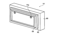
次に、キャッピング部材60の構造について図3および図4を参照して詳細に説明する。ここで、図3は、図1に示すインクジェット記録装置のキャッピング部材の概略構成を示す斜視図であり、図4(A)は、図3に示すキャッピング部材の正面図、図4(B)は、図4(A)のIVB−IVB線における断面図、図4(C)は、図4(A)のIVC−IVC線における断面図である。
キャッピング部材60は、上述のように、インクの循環停止時や長時間描画を行わない間に、吐出ヘッド12の全ての吐出口を外気との連通を断った状態にすることにより、吐出口に残存するインクQの蒸発による乾燥固着を防止するものである。
キャッピング部材60は、連通口60aを有し吐出ヘッド12と接触するキャッピング用ゴム部材64と、キャッピング用ゴム部材64を支持するゴム保持部材62と、吐出ヘッド12への押しつけ圧を調整する押しつけ圧調整ばね66と、ケース61と、連通口60aと連通配管59を接続する連通チューブ68とを有する。
Next, the structure of the capping
As described above, the capping
The capping
キャッピング用ゴム部材64は、吐出ヘッド12の吐出口配設面よりも広い矩形面を有する蓋部材であり、吐出ヘッド12に対向する側の矩形面の外周部が、吐出ヘッド12側に凸の構造を有する。キャッピング部材60を吐出ヘッド12に装着したときには、キャッピング用ゴム部材64の外周部のみが、吐出ヘッドの吐出口配設面と接触する。これにより、吐出ヘッド12の吐出口配設面に接触して、吐出口と外気との連通を断つことができる。このように、吐出ヘッド12の吐出口と直接接触することなく、吐出口を外気との連通を断つことができる構造にすることで、吐出口が複雑な形状の場合や、インクガイドを備える場合の吐出ヘッドも本発明のインクジェット記録装置に用いることができる。
キャッピング用ゴム部材64は、吐出口配設面との密着性と耐インク性を有することが好ましく、例えば、柔軟性を有するゴムあるいは発泡部材で形成され、具体的には、硬度60度以下のNMRゴム、フッ素ゴム等が例示される。
また、キャッピング部材60の表面には、連通口60aが形成されている。図示例では、連通口を2箇所に形成したが連通口の数は特に限定されず、いくつ設けてもよい。
The capping
The capping
A communication port 60 a is formed on the surface of the capping
ゴム保持部材62は、キャッピング用ゴム部材64の吐出ヘッド12との接触面と反対側の面に設けられ、キャッピング用ゴム部材64を保持する。ゴム保持部材62は、剛性と耐インク性のある材料で形成され、具体的には、スレンレス、アルミ等の金属か、ポリエーテルエーテルケトン(PEEK)、ポリカーボネート(PC)、硬質塩化ビニル等の硬質プラスチックが例示される。
The
押しつけ圧調整ばね66は、ゴム保持部材62とケース61との間に配置され、キャッピング用ゴム部材64の吐出ヘッド12への押しつけ圧を調整する。ここで、押しつけ圧調整ばね66は、図4に示すように、所定間隔毎に複数設け、吐出ヘッド12への押しつけ圧が一定となるようにすることが好ましい。
The pressing
ケース61は、ゴム保持部材62を図4(C)矢印方向に移動可能に収容し保持するためのケースである。ケース61内に収容され、キャッピング用ゴム部材64を保持したゴム保持部材62は、押し付け圧調整ばね56により適切な圧力で吐出ヘッド12の吐出口配設面に押しつける。また、複数の押しつけ圧調整ばね66によりゴム保持部材62を保持しているため、キャッピング用ゴム部材64と吐出ヘッド12の吐出口配置面が斜めに配置されていても、ケース61を吐出ヘッド12の吐出口配置面に向けて前進させて、キャッピング用ゴム部材64を吐出ヘッド12の吐出口配置面に接触させたときに、キャッピング用ゴム部材64が傾いて吐出ヘッド12の吐出口配置面と平行な状態で接触する。これにより、吐出ヘッド12の吐出口配置面がキャッピング用ゴム部材64でしっかりと封止される。ケース61全体は、例えば、モータ機構や圧力機構により吐出ヘッド12に向かって移動させられる構成であればよく、キャッピングを行う際には、吐出ヘッド12の吐出口配設面に当接するように移動させられる。
ここで、ケース61は、剛性と耐インク性のある材料で形成されることが好ましく、具体的には、スレンレス、アルミ等の金属か、ポリエーテルエーテルケトン(PEEK)、ポリカーボネート(PC)、硬質塩化ビニル等の硬質プラスチックが好ましい。
The case 61 is a case for accommodating and holding the
Here, the case 61 is preferably formed of a material having rigidity and ink resistance. Specifically, the case 61 is made of a metal such as stainless steel or aluminum, polyether ether ketone (PEEK), polycarbonate (PC), or hard. Rigid plastics such as vinyl chloride are preferred.
連通チューブ68は、キャッピング用ゴム部材64、ゴム保持部材62およびケース61とを貫通して設けられている。連通チューブ68のキャッピング用ゴム部材64側の端部は連通口60aを形成し、ケース61側の端部は、図示しない連通配管59と接続される。
The
ここで、本発明において、キャッピング部材60の吐出ヘッド12への装着および離脱の制御はどのように行ってもよく、例えば、吐出ヘッド12による記録時(稼動時)以外は、キャッピング部材60を装着させるようにしてもよく、または、所定時間記録が行われなかった場合にキャッピング部材を装着させるようにしてもよい。
Here, in the present invention, the attachment and detachment of the capping
ここで、本発明においては、キャッピング部材60は、前記キャップ移動手段が非稼動の状態(電源遮断状態)において、本実施形態のように、スプリングや弾性部材等の動力が不要な付勢部材によってキャップ部材を押圧することにより、吐出口を外気との連通が断たれた状態とする構成とするのが好ましい。
上記構成を有することにより、吐出口の外気との連通が断たれた状態中に停電が発生しても、吐出口を外気との連通が断たれた状態に保つことができ、さらにインク循環の停止時における吐出ヘッドおよび各インクタンクの外気との連通が断たれた状態を確実に保つことができる。
Here, in the present invention, the capping
By having the above configuration, even if a power failure occurs while communication with the outside air at the discharge port is interrupted, the discharge port can be maintained in a state where communication with the outside air is interrupted, and ink circulation can be prevented. It is possible to reliably maintain a state in which the communication between the ejection head and the outside air of each ink tank is stopped at the time of stopping.
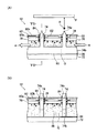
図5(A)および(B)は、記録装置10における吐出ヘッド12の具体的な構造を説明する模式図であり、図5(A)は、吐出ヘッド12の一部を示す模式的断面図、図5(B)は、図5(A)のVB−VB線における模式的断面図である。記録装置10においては、負の高電圧に帯電(バイアス電圧を帯電)された記録媒体Pを吐出部の配列方向(後述する行方向)と直交する方向に走査搬送しつつ、記録画像すなわち供給された画像データに応じて吐出ヘッド12の各吐出部を変調駆動して吐出をon/offすることにより、インク液滴Rをオンデマンドで吐出して、記録媒体Pに目的とする画像を記録する。
なお、吐出ヘッド12は、複数の吐出口を2次元的に備えるマルチチャンネルヘッドであるが、ここでは、その構成を明確に示すために、2つの吐出部のみを示してある。
5A and 5B are schematic views for explaining a specific structure of the
The
吐出ヘッド12は、ヘッド基板72と、インクガイド74と、吐出口基板76と、吐出電極を構成する吐出電極78と、浮遊導電板86とを備えている。吐出ヘッド12は、インク滴Rの吐出(飛翔)ポイントとなるインクガイド74の先端が、記録媒体Pと対向するように配置されている。
The
ヘッド基板72および吐出口基板76は、吐出ヘッド12の全吐出口に共通な平板基板であり、絶縁性材料から構成されている。ヘッド基板72および吐出口基板76は、所定の間隔をあけて配置され、その間にインク流路88が形成されている。インク流路88内のインクQは、吐出電極78に印加される電圧と同極性に帯電した色材粒子を含み、記録時には、前記インク循環系によって、所定方向、図5(A)に示す例ではインク流路88内を右側から左側(図中矢印a方向)へ向かって所定の速度(例えば、200mm/sのインク流)で循環される。以下では、インク中の色材粒子が正帯電している場合を例にとって説明する。
The
吐出口基板76には、インクQの吐出口となる吐出口84が穿孔されており、この吐出口84は、所定の間隔で2次元的に複数配置されている。また、吐出口84の中央部には、インクQの吐出(飛翔)ポイントを定めるためのインクガイド74が配置されている。
In the
インクガイド74は、突状先端部分74aを持つ所定厚みの絶縁性樹脂製平板からなり、各吐出口84に対応する位置に、ヘッド基板72の上に配置されている。インクガイド74は、同じ列(図5(A)における左右方向、図5(B)における紙面垂直方向)に配列される複数のインクガイド74に共通の基部64bを有しており、この基部64bがヘッド基板72上に、浮遊導電板86を挟んで固定されている。
The
また、インクガイド74の先端部分74aは、吐出ヘッド12の記録媒体P側の最表面から突出するように配置されている。先端部分74aの形状および構成は、インクQ(インク滴R)の吐出ポイントを安定させ、かつ、先端部分74aにおいて、インクQを十分に供給し、インクQ中の色材粒子を好ましい状態に濃縮させることができるように設定される。例えば、先端部分74aを吐出方向に向けて次第に細くした形状のものや、インク案内溝となる切り欠きを図中上下方向に形成したもの、先端部分74aの誘電率を実質的に大きくするために、先端部分74aに金属を蒸着したものなどが好適である。
Further, the
吐出口基板76の記録媒体P側の面(図中、上面)には、各吐出口84を囲むように、吐出電極78が配置されている。また、吐出口基板76の記録媒体P側には、吐出電極78の上方(上面)を覆う絶縁層80aと、吐出電極78の上方に絶縁層80aを介して配置されるシート状のガード電極82と、ガード電極82の上面を覆う絶縁層80bとが設けられている。
On the surface of the
吐出電極78は、吐出口基板76に開孔された吐出口84の周囲を囲むように、吐出口基板76の図中上側、すなわち記録媒体P側の表面に、吐出部毎にリング状に、すなわち円形電極として配置されている。なお、吐出電極78の電極形状は、円形電極に限定されず、略円形であっても、分割円形電極であっても、平行電極または略平行電極であっても矩形電極であっても良い。
The
画像の記録時には、インクガイド74と対向する位置には、インク中の帯電した色材粒子と極性が反対となる電圧に帯電された記録媒体Pが、図示しない搬送手段に保持されて一定速度で搬送される。記録媒体Pは負の高電圧(例えば、−1500V)に帯電されており、吐出電極78との間に、インクQを吐出させない程度の所定の電界が形成されている。
記録媒体Pが所定の位置に搬送されると、吐出ヘッド12には、記録媒体Pの搬送タイミングおよび画像データに応じて駆動信号が供給され、各吐出ヘッド12は、これに応じて、吐出電極78を変調駆動し、インク吐出を画像データに応じて変調してon/offする。
At the time of recording an image, a recording medium P charged to a voltage having a polarity opposite to that of the charged color material particles in the ink is held at a constant speed by a conveying means (not shown) at a position facing the
When the recording medium P is transported to a predetermined position, a drive signal is supplied to the
吐出電極78が吐出オフ状態(吐出待機状態)のときは、パルス電圧は0Vまたは低電圧とされる。この状態では、吐出部の電界強度はバイアス電圧(または、バイアス電圧にオフ状態のパルス電圧が重畳された電圧)による電界強度となっており、これはインクQの吐出に必要な強度よりも低く設定されているため、インクQの吐出は行われない。この吐出待機状態では、インクQには、バイアス電圧とインクQの色材粒子(荷電粒子)の荷電とのクーロン引力、色材粒子間のクーロン反発力、キャリア液の粘性、表面張力、誘電分極力等が作用し、これらが連成して、色材粒子やキャリア液が移動し、吐出口84から若干盛り上がったメニスカス状となってバランスが取れている。
また、このクーロン引力等によって、色材粒子は、いわゆる電気泳動でバイアス電圧が帯電された記録媒体Pに向かって移動する。すなわち、吐出口84のメニスカスにおいては、インクQが濃縮された状態となっている。
When the
In addition, the colorant particles move toward the recording medium P charged with a bias voltage by so-called electrophoresis due to the Coulomb attractive force or the like. That is, the ink Q is concentrated in the meniscus of the
吐出電極78が吐出オン状態のときは、パルス電圧が印加され、バイアス電圧に高電圧のパルス電圧(例えば、400〜600V)が重畳されて、吐出部の電界強度はインクQが吐出するのに十分な強度となり、先の連成に、さらにこの駆動電圧の重畳によって連成された運動が起こり、静電力によって色材粒子およびキャリア液がバイアス電圧(対向電極)側すなわち記録媒体P側に引っ張られ、メニスカスが成長して、その上部から略円錐状のインク液柱いわゆるテーラーコーンが形成される。また、先と同様に、色材粒子は電気泳動によってメニスカスに移動しており、メニスカスのインクQは濃縮され、色材粒子を多数有する、ほぼ均一な高濃度状態となっている。
駆動電圧の印加開始後、さらに有限な時間が経過すると、色材粒子の移動等により、電界強度の高いメニスカスの先端部分で、主に色材粒子に作用する力(クーロン力等)とキャリア液の表面張力とのバランスが崩れ、メニスカスが急激に伸びて曳糸と呼ばれる直径数〜数十μm程度の細長いインク液柱が形成される。
When the
When a finite time has passed after the start of the application of the drive voltage, the force acting on the color material particles (Coulomb force, etc.) and the carrier liquid mainly at the tip of the meniscus having a high electric field strength due to the movement of the color material particles, etc. The balance with the surface tension is lost, the meniscus grows abruptly, and a slender ink liquid column having a diameter of about several to several tens of μm called a kite string is formed.
さらに有限な時間が経過すると曳糸が成長し、この曳糸の成長、レイリー/ウエーバー不安定性によって発生する振動、メニスカス内における色材粒子の分布不均一、メニスカスにかかる静電界の分布不均一等の相互作用によって曳糸が分断され、インク液滴Rとなって吐出/飛翔し、かつ、バイアス電圧にも引っ張られて、記録媒体Pに着弾する。
曳糸の成長および分断は、さらにはメニスカス(曳糸)への色材粒子の移動は、駆動電圧の印加中は連続して発生する。また、駆動電圧の印加を終了した時点で、バイアス電圧のみが印加されたメニスカスの状態に戻る。
記録媒体P上におけるインクの1ドットは、通常、この1回(1パルス)の駆動電圧の印加によるものであり、従って、1ドットは、この1回の駆動電圧の印加によって曳糸から分断して吐出した複数のインク液滴Rによって形成される。
このインク滴Rのサイズは極めて小さいため、解像度の高い、高画質な画像記録を行うことができる。
Further, when a finite time elapses, the silk thread grows, and the growth of the silk thread, vibration caused by Rayleigh / Weber instability, uneven distribution of colorant particles in the meniscus, uneven distribution of electrostatic field on the meniscus, etc. As a result of this interaction, the kite string is divided, ejected / flyed as ink droplets R, and pulled by the bias voltage to land on the recording medium P.
The growth and splitting of the kite string, and further the movement of the color material particles to the meniscus (punch kite) occur continuously during the application of the drive voltage. When the application of the drive voltage is finished, the state returns to the meniscus state where only the bias voltage is applied.
One dot of ink on the recording medium P is usually obtained by applying the drive voltage once (one pulse). Therefore, one dot is separated from the string by applying the drive voltage once. Formed by a plurality of ink droplets R ejected in this manner.
Since the size of the ink droplet R is extremely small, high-resolution and high-quality image recording can be performed.
このように、画像データに応じて、記録媒体Pの全幅に亘って配置された各吐出部の吐出電極78のオン、オフが制御され、所定速度で搬送される記録媒体Pに対して所定のタイミングでインク吐出が行われることにより、記録媒体Pに2次元画像が記録される。
Thus, on / off of the
ガード電極82は、隣接する吐出部の吐出電極78の間に配置され、隣接する吐出部のインクガイド74の間に生じる電界干渉を抑制するためのものである。ガード電極82は、吐出ヘッド12の全吐出部に共通な金属板などのシート状の電極であり、2次元的に配列されている各吐出口84の周囲に形成された吐出電極78に相当する部分が穿孔されている。ガード電極82を設けることによって、吐出口84を高密度に配置した場合にも、隣接する吐出口84の電界の影響を最小限にし、ドットサイズおよびドットの描画位置を常に安定して保つことができる。
The
ヘッド基板72のインク流路88側の表面には、浮遊導電板86が配置されている。浮遊導電板86は、電気的に絶縁状態(ハイインピーダンス状態)とされており、画像の記録時に、吐出部に印加された電圧値に応じて、誘起された誘導電圧を発生し、インク流路88内のインクQにおいて、その色材粒子を吐出口基板76側へ泳動させる。また、浮遊導電板86の表面には、電気絶縁性である被覆膜(図示せず)が形成されており、インクへの電荷注入等によりインクの物性や成分が不安定化することが防止されている。この絶縁性被覆膜は、インクに対して耐腐食性を有するものが用いられる。
A floating
浮遊導電板86を設けることにより、インク流路88内のインクQ中の色材粒子を吐出口基板76側へ泳動させて、吐出口基板76の吐出口84を通過するインクQ内の色材粒子の濃度を所定濃度に高めることができ、インクガイド74の先端部分74aに濃縮させて、インク液滴Rとして吐出させるインクQ内の色材粒子の濃度を所定濃度に安定させることができる。
By providing the floating
なお、図示例においては、吐出電極を単層電極構造としているが、これ以外にも、例えば、列方向に接続された第1吐出電極と、行方向に接続された第2吐出電極とを備える2層電極構造とし、第1吐出電極と第2吐出電極とをマトリクス状に配列してマトリクス駆動を行うものとしてもよい。このようなマトリクス駆動方式によれば、吐出電極の高集積化とドライバ配線の簡素化の両方を同時に実現できる。 In the illustrated example, the discharge electrode has a single-layer electrode structure, but in addition to this, for example, a first discharge electrode connected in the column direction and a second discharge electrode connected in the row direction are provided. A two-layer electrode structure may be used, and the first discharge electrode and the second discharge electrode may be arranged in a matrix to perform matrix driving. According to such a matrix driving method, both high integration of ejection electrodes and simplification of driver wiring can be realized simultaneously.
また、この態様では、インクQ中の色材粒子を正帯電させ、記録媒体側を負の高電圧に帯電させているが、これに限定されず、逆に、インク中の色材粒子を負に帯電させ、記録媒体P側を正の高電圧に帯電させても良い。このように、色材粒子の極性を本態様と逆にする場合には、対向電極、記録媒体Pの帯電ユニット、各々の吐出部の吐出電極78への印加電圧極性等を上記の例と逆にすれば良い。
In this embodiment, the color material particles in the ink Q are positively charged and the recording medium side is charged to a negative high voltage. However, the present invention is not limited to this, and conversely, the color material particles in the ink are negatively charged. The recording medium P side may be charged to a positive high voltage. As described above, when the polarity of the color material particles is reversed from that of the present embodiment, the polarity of the voltage applied to the counter electrode, the charging unit of the recording medium P, the
ここで、本発明の記録装置に用いられるインクについて説明する。
インクQは、色材粒子をキャリア液に分散することにより得られる。キャリア液は、高い電気抵抗率(109Ω・cm以上、好ましくは1010Ω・cm以上)を有する誘電性の液体(非水溶媒)であるのが好ましい。キャリア液の電気抵抗が低いと、制御電極に印加される駆動電圧により、キャリア液自身が電荷注入を受けて帯電してしまい、色材粒子の濃縮がおこらない。また、電気抵抗の低いキャリア液は、隣接する制御電極間での電気的導通を生じさせる懸念もあるため不向きである。
Here, the ink used in the recording apparatus of the present invention will be described.
Ink Q is obtained by dispersing colorant particles in a carrier liquid. The carrier liquid is preferably a dielectric liquid (nonaqueous solvent) having a high electric resistivity (10 9 Ω · cm or more, preferably 10 10 Ω · cm or more). If the electric resistance of the carrier liquid is low, the carrier liquid itself is charged by charge injection due to the drive voltage applied to the control electrode, and the colorant particles do not concentrate. In addition, a carrier liquid having a low electrical resistance is not suitable because there is a concern of causing electrical conduction between adjacent control electrodes.
キャリア液として用いられる誘電性液体の比誘電率は、5以下が好ましく、より好ましくは4以下、さらに好ましくは3.5以下である。このような比誘電率の範囲とすることによって、キャリア液中の色材粒子に有効に電界が作用し、泳動が起こりやすくなる。
なお、このようなキャリア液の固有電気抵抗の上限値は1016Ωcm程度であるのが望ましく、比誘電率の下限値は1.9程度であるのが望ましい。キャリア液の電気抵抗が上記範囲であるのが望ましい理由は、電気抵抗が低くなると、低電界下でのインクの吐出が悪くなるからであり、比誘電率が上記範囲であるのが望ましい理由は、誘電率が高くなると溶媒の分極により電界が緩和され、これにより形成されたドットの色が薄くなったり、滲みを生じたりするからである。
The relative dielectric constant of the dielectric liquid used as the carrier liquid is preferably 5 or less, more preferably 4 or less, and still more preferably 3.5 or less. By setting the relative dielectric constant in such a range, an electric field effectively acts on the colorant particles in the carrier liquid, and migration easily occurs.
The upper limit value of the specific electric resistance of such a carrier liquid is preferably about 10 16 Ωcm, and the lower limit value of the relative dielectric constant is preferably about 1.9. The reason why it is desirable that the electric resistance of the carrier liquid is in the above range is that if the electric resistance is low, ink ejection under a low electric field is deteriorated, and the reason why the relative dielectric constant is preferably in the above range is the reason. This is because, when the dielectric constant increases, the electric field is relaxed by the polarization of the solvent, and the color of the dots formed thereby becomes thin or causes blurring.
キャリア液として用いられる誘電性液体としては、好ましくは直鎖状もしくは分岐状の脂肪族炭化水素、脂環式炭化水素、または芳香族炭化水素、および、これらの炭化水素のハロゲン置換体がある。例えば、へキサン、ヘプタン、オクタン、イソオクタン、デカン、イソデカン、デカリン、ノナン、ドデカン、イソドデカン、シクロヘキサン、シクロオクタン、シクロデカン、ベンゼン、トルエン、キシレン、メシチレン、アイソパーC、アイソパーE、アイソパーG、アイソパーH、アイソパーL、アイソパーM(アイソパー:エクソン社の商品名)、シェルゾール70、シェルゾール71(シェルゾール:シェルオイル社の商品名)、アムスコOMS、アムスコ460溶剤(アムスコ:スピリッツ社の商品名)、シリコーンオイル(例えば、信越シリコーン社製KF−96L)等を単独あるいは混合して用いることができる。 The dielectric liquid used as the carrier liquid is preferably a linear or branched aliphatic hydrocarbon, alicyclic hydrocarbon, or aromatic hydrocarbon, and halogen-substituted products of these hydrocarbons. For example, hexane, heptane, octane, isooctane, decane, isodecane, decalin, nonane, dodecane, isododecane, cyclohexane, cyclooctane, cyclodecane, benzene, toluene, xylene, mesitylene, Isopar C, Isopar E, Isopar G, Isopar H, Isopar L, Isopar M (isopar: trade name of Exxon), Shellsol 70, Shellsol 71 (shellsol: trade name of Shell Oil), Amsco OMS, Amsco 460 Solvent (trade name of Amsco: Spirits), Silicone oil (for example, KF-96L manufactured by Shin-Etsu Silicone) or the like can be used alone or in combination.
このようなキャリア液に分散される色材粒子は、色材自身を色材粒子としてキャリア液中に分散させてもよいが、好ましくは、定着性を向上させるための分散樹脂粒子を含有させる。分散樹脂粒子を含有させる場合、顔料などは分散樹脂粒子の樹脂材料で被覆して樹脂被覆粒子とする方法などが一般的であり、染料などは分散樹脂粒子を着色して着色粒子とする方法などが一般的である。 The colorant particles dispersed in such a carrier liquid may be dispersed in the carrier liquid as the colorant itself as colorant particles, but preferably contain dispersed resin particles for improving fixability. When the dispersed resin particles are included, the pigment is generally coated with the resin material of the dispersed resin particles to form resin-coated particles, and the dye is colored with the dispersed resin particles to form colored particles. Is common.
色材としては、従来か流路クジェットインク組成物、印刷用(油性)インキ組成物、あるいは静電写真用液体現像剤に用いられている顔料および染料であればどれでも使用可能である。
色材として用いる顔料としては、無機顔料、有機顔料を問わず、印刷の技術分野で一般に用いられているものを使用することができる。具体的には、例えば、カーボンブラック、カドミウムレッド、モリブデンレッド、クロムイエロー、カドミウムイエロー、チタンイエロー、酸化クロム、ビリジアン、コバルトグリーン、ウルトラマリンブルー、プルシアンブルー、コバルトブルー、アゾ系顔料、フタロシアニン系顔料、キナクリドン系顔料、イソインドリノン系顔料、ジオキサジン系顔料、スレン系顔料、ペリレン系顔料、ペリノン系顔料、チオインジゴ系顔料、キノフタロン系顔料、金属錯体顔料、等の従来公知の顔料を特に限定なく用いることができる。
色材として用いる染料としては、アゾ染料、金属錯塩染料、ナフトール染料、アントラキノン染料、インジゴ染料、カーボニウム染料、キノンイミン染料、キサンテン染料、アニリン染料、キノリン染料、ニトロ染料、ニトロソ染料、ベンゾキノン染料、ナフトキノン染料、フタロシアニン染料、金属フタロシアニン染料、等の油溶性染料が好ましく例示される。
As the coloring material, any of conventional pigments and dyes used in a flow channel kujet ink composition, a printing (oil-based) ink composition, or an electrophotographic liquid developer can be used.
As the pigment used as the color material, regardless of inorganic pigments or organic pigments, those generally used in the technical field of printing can be used. Specifically, for example, carbon black, cadmium red, molybdenum red, chrome yellow, cadmium yellow, titanium yellow, chromium oxide, viridian, cobalt green, ultramarine blue, Prussian blue, cobalt blue, azo pigment, phthalocyanine pigment Conventionally known pigments such as quinacridone pigments, isoindolinone pigments, dioxazine pigments, selenium pigments, perylene pigments, perinone pigments, thioindigo pigments, quinophthalone pigments and metal complex pigments are used without particular limitation. be able to.
As dyes used as coloring materials, azo dyes, metal complex dyes, naphthol dyes, anthraquinone dyes, indigo dyes, carbonium dyes, quinoneimine dyes, xanthene dyes, aniline dyes, quinoline dyes, nitro dyes, nitroso dyes, benzoquinone dyes, naphthoquinone dyes And oil-soluble dyes such as phthalocyanine dyes and metal phthalocyanine dyes.
さらに、分散樹脂粒子としては、例えば、ロジン類、ロジン変性フェノール樹脂、アルキッド樹脂、(メタ)アクリル系ポリマー、ポリウレタン、ポリエステル、ポリアミド、ポリエチレン、ポリブタジエン、ポリスチレン、ポリ酢酸ビニル、ポリビニールアルコールのアセタール変性物、ポリカーボネート等を挙げられる。
これらのうち、粒子形成の容易さの観点から、重量平均分子量が2,000〜1000,000の範囲内であり、かつ多分散度(重量平均分子量/数平均分子量)が、1.0〜5.0の範囲内であるポリマーが好ましい。さらに、前記定着の容易さの観点から、軟化点、ガラス転移点または、融点のいずれか1つが40℃〜120℃の範囲内にあるポリマーが好ましい。
Further, as dispersed resin particles, for example, rosins, rosin-modified phenol resins, alkyd resins, (meth) acrylic polymers, polyurethane, polyester, polyamide, polyethylene, polybutadiene, polystyrene, polyvinyl acetate, polyvinyl alcohol, polyvinyl alcohol, acetal-modified Products, polycarbonate and the like.
Among these, from the viewpoint of ease of particle formation, the weight average molecular weight is in the range of 2,000 to 1,000,000 and the polydispersity (weight average molecular weight / number average molecular weight) is 1.0 to 5 Polymers in the range of 0.0 are preferred. Furthermore, from the viewpoint of ease of fixing, a polymer having any one of a softening point, a glass transition point, and a melting point within a range of 40 ° C. to 120 ° C. is preferable.
インクQにおいて、色材粒子の含有量(色材粒子あるいはさらに分散樹脂粒子の合計含有量)は、インク全体に対して0.5〜30重量%の範囲で含有されることが好ましく、より好ましくは1.5〜25重量%、さらに好ましくは3〜20重量%の範囲で含有されることが望ましい。色材粒子の含有量が少なくなると、印刷画像濃度が不足したり、インクQと記録媒体P表面との親和性が得られ難くなって強固な画像が得られなくなったりするなどの問題が生じ易くなり、一方、含有量が多くなると均一な分散液が得られにくくなったり、インクジェットヘッド等でのインクQの目詰まりが生じやすく、安定なインク吐出が得られにくいなどの問題が生じるからである。 In the ink Q, the content of the color material particles (the total content of the color material particles or further dispersed resin particles) is preferably contained in the range of 0.5 to 30% by weight with respect to the whole ink, and more preferably. Is preferably contained in the range of 1.5 to 25% by weight, more preferably 3 to 20% by weight. If the content of the colorant particles is reduced, problems such as insufficient printed image density or difficulty in obtaining a strong image due to difficulty in obtaining the affinity between the ink Q and the surface of the recording medium P are likely to occur. On the other hand, when the content increases, it becomes difficult to obtain a uniform dispersion, or the ink Q is easily clogged with an inkjet head or the like, and it is difficult to obtain stable ink discharge. .
また、キャリア液に分散された色材粒子の平均粒径は、0.1〜5μmが好ましく、より好ましくは0.2〜1.5μmであり、更に好ましくは0.4〜1.0μmである。この粒径はCAPA−500(堀場製作所(株)製商品名)により求めたものである。 The average particle diameter of the colorant particles dispersed in the carrier liquid is preferably 0.1 to 5 μm, more preferably 0.2 to 1.5 μm, and still more preferably 0.4 to 1.0 μm. . This particle size is determined by CAPA-500 (trade name, manufactured by Horiba, Ltd.).
色材粒子をキャリア液に分散させた後(必要に応じて、分散剤を使用しても可)、荷電制御剤をキャリア液に添加することにより色材粒子を荷電して、荷電した色材粒子をキャリア液に分散してなるインクQとする。なお、色材粒子の分散時には、必要に応じて、分散媒を添加してもよい。
荷電制御剤は、一例として、電子写真液体現像剤に用いられている各種のものが利用可能である。また、「最近の電子写真現像システムとトナー材料の開発・実用化」139〜148頁、電子写真学会編「電子写真技術の基礎と応用」497〜505頁(コロナ社、1988年刊)、原崎勇次「電子写真」16(No.2)、44頁(1977年)等に記載の各種の荷電制御剤も利用可能である。
After the colorant particles are dispersed in the carrier liquid (a dispersant may be used if necessary), the chargeant is added to the carrier liquid to charge the colorant particles, and the charged colorant The ink Q is obtained by dispersing particles in a carrier liquid. When dispersing the colorant particles, a dispersion medium may be added as necessary.
As an example of the charge control agent, various materials used in electrophotographic liquid developers can be used. Also, “Recent development and commercialization of electrophotographic development systems and toner materials”, pages 139 to 148, “The Basics and Applications of Electrophotographic Technology” edited by Electrophotographic Society, pages 497 to 505 (Corona Inc., published in 1988), Yuji Harasaki Various charge control agents described in “Electrophotography” 16 (No. 2), p. 44 (1977) can also be used.
なお、色材粒子は、制御電極に印加される駆動電圧と同極性であれば、正電荷および負電荷のいずれに荷電したものであってもよい。
また、色材粒子の荷電量は、好ましくは5〜200μC/g、より好ましくは10〜150μC/g、さらに好ましくは15〜100μC/gの範囲である。
The color material particles may be positively charged or negatively charged as long as they have the same polarity as the drive voltage applied to the control electrode.
The charge amount of the color material particles is preferably in the range of 5 to 200 μC / g, more preferably 10 to 150 μC / g, and still more preferably 15 to 100 μC / g.
また、荷電制御剤の添加によって誘電性溶媒の電気抵抗が変化することもあるため、下記に定義する分配率Pを、好ましくは50%以上、より好ましくは60%以上、さらに好ましくは70%以上とする。
P=100×(σ1−σ2)/σ1
ここで、σ1は、インクQの電気伝導度、σ2は、インクQを遠心分離器にかけた上澄みの電気伝導度である。電気伝導度は、LCRメーター(安藤電気(株)社製AG−4311)および液体用電極(川口電機製作所(株)社製LP−05型)を使用し、印加電圧5V、周波数1kHzの条件で測定を行った値である。また遠心分離は、小型高速冷却遠心機(トミー精工(株)社製SRX−201)を使用し、回転速度14500rpm、温度23℃の条件で30分間行った。
以上のようなインクQを用いることによって、荷電粒子の泳動が起こりやすくなり、濃縮しやすくなる。
In addition, since the electric resistance of the dielectric solvent may change due to the addition of the charge control agent, the distribution ratio P defined below is preferably 50% or more, more preferably 60% or more, and even more preferably 70% or more. And
P = 100 × (σ1−σ2) / σ1
Here, σ1 is the electrical conductivity of the ink Q, and σ2 is the electrical conductivity of the supernatant obtained by applying the ink Q to the centrifuge. The electrical conductivity was measured using an LCR meter (AG-4311 manufactured by Ando Electric Co., Ltd.) and an electrode for liquid (LP-05 type manufactured by Kawaguchi Electric Manufacturing Co., Ltd.) under the conditions of an applied voltage of 5 V and a frequency of 1 kHz. This is the measured value. Centrifugation was performed for 30 minutes using a small high-speed cooling centrifuge (Tomy Seiko Co., Ltd. SRX-201) under conditions of a rotational speed of 14500 rpm and a temperature of 23 ° C.
By using the ink Q as described above, migration of charged particles is likely to occur and concentration is facilitated.
インクQの電気伝導度は、100〜3000pS/cmが好ましく、より好ましくは150〜2500pS/cm、さらに好ましくは200〜2000pS/cmである。以上のような電気伝導度の範囲とすることによって、制御電極に印加する電圧が極端に高くならず、隣接する記録電極間での電気的導通を生じさせる懸念もない。
また、インクQの表面張力は、15〜50mN/mの範囲が好ましく、より好ましくは15.5〜45mN/m、さらに好ましくは16〜40mN/mの範囲である。表面張力をこの範囲とすることによって、制御電極に印加する電圧が極端に高くならず、ヘッド周りにインクが漏れ広がり汚染することがない。
さらに、インクQの粘度は0.5〜5mPa・secが好ましく、より好ましくは0.6〜3.0mPa・sec、さらに好ましくは0.7〜2.0mPa・secである。
The electrical conductivity of the ink Q is preferably 100 to 3000 pS / cm, more preferably 150 to 2500 pS / cm, and still more preferably 200 to 2000 pS / cm. By setting the electric conductivity in the above range, the voltage applied to the control electrode does not become extremely high, and there is no fear of causing electrical continuity between adjacent recording electrodes.
The surface tension of the ink Q is preferably in the range of 15 to 50 mN / m, more preferably 15.5 to 45 mN / m, and still more preferably 16 to 40 mN / m. By setting the surface tension within this range, the voltage applied to the control electrode does not become extremely high, and the ink does not leak around the head to be contaminated.
Furthermore, the viscosity of the ink Q is preferably 0.5 to 5 mPa · sec, more preferably 0.6 to 3.0 mPa · sec, and still more preferably 0.7 to 2.0 mPa · sec.
このようなインクQは、一例として、色材粒子をキャリア液に分散して粒子化し、かつ、荷電調整剤を分散媒に添加して、色材粒子に荷電を生じさせることで、調製できる。具体的な方法としては、以下の方法が例示される。
(1)色材あるいはさらに分散樹脂粒子をあらかじめ混合(混練)した後、必要に応じて分散剤を用いてキャリア液に分散し、荷電調整剤を加える方法。
(2)色材、あるいはさらに分散樹脂粒子および分散剤を、キャリア液に同時に添加して、分散し、荷電調整剤を加える方法。
(3)色材および荷電調整剤、あるいはさらに分散樹脂粒子および分散剤を、同時にキャリア液に添加して、分散する方法。
As an example, such an ink Q can be prepared by dispersing color material particles in a carrier liquid to form particles, and adding a charge adjusting agent to the dispersion medium to cause the color material particles to be charged. Specific methods include the following methods.
(1) A method in which a color material or further dispersed resin particles are mixed (kneaded) in advance, and then dispersed in a carrier liquid using a dispersant as required, and a charge adjusting agent is added.
(2) A method in which a coloring material, or further dispersed resin particles and a dispersing agent are simultaneously added to a carrier liquid, dispersed, and a charge adjusting agent is added.
(3) A method in which a coloring material and a charge adjusting agent, or further dispersed resin particles and a dispersing agent are simultaneously added to a carrier liquid and dispersed.
以上、本発明のインクジェット記録装置ついて詳細に説明したが、本発明は、上記実施形態に限定はされず、本発明の要旨を逸脱しない範囲において、各種の改良や変更を行ってもよいのは、もちろんのことである。 The inkjet recording apparatus of the present invention has been described in detail above. However, the present invention is not limited to the above-described embodiment, and various improvements and modifications may be made without departing from the gist of the present invention. Of course.
例えば、以上の例は、本発明のインクジェット記録装置を、色材粒子(色材を含む荷電した粒子)をキャリア液に分散してなるインクを用いる濃縮タイプの静電式インクジェット記録装置に利用したものであるが、本発明は、これに限定はされず、荷電粒子を含有するインクを用いない、非濃縮タイプの静電式インクジェット記録装置にも好適に利用可能である。 For example, in the above example, the ink jet recording apparatus of the present invention is used for a concentration type electrostatic ink jet recording apparatus that uses ink in which color material particles (charged particles including a color material) are dispersed in a carrier liquid. However, the present invention is not limited to this, and can be suitably used for a non-concentrated electrostatic ink jet recording apparatus that does not use ink containing charged particles.
10、100 インクジェット記録装置
12 吐出ヘッド(インクジェットヘッド)
12a、60a 連通口
16 メインタンク
18、102 供給サブタンク
18a、20a オーバーフロー管
18b、20b、23a、24a、102b 開口
20 回収サブタンク
22 インク補充手段
23 高濃度補充液タンク
24 希釈補充液タンク
25 インク循環ポンプ
26 異物除去手段
27、29 フィルタ
28 濃度センサ
30 インク循環経路
32 共通供給配管
34、104 第1供給配管
36 第2供給配管
37 分岐配管
38 第3供給配管
39 空隙
40 第1回収配管
42 第2回収配管
44 第3回収配管
46 共通回収配管
48、50、52 補充用配管
48a、50a 補充制御バルブ
53 洗浄手段
54 洗浄液供給配管
56 洗浄液回収配管
54a、56a 三方制御弁
58 洗浄液循環ポンプ
59 連通配管
60 キャッピング部材
61 ケース
62 ゴム保持部材
64 キャッピング用ゴム部材
66 押しつけ圧調整ばね
68 連通チューブ
72 ヘッド基板
74b 基部
76 吐出口基板
80b 絶縁層
82 ガード電極
84 吐出口
86 浮遊導電板
10, 100
12a,
32
Claims (13)
前記インクを貯留するメインタンクと、
前記メインタンクから供給されるインクを貯留し、前記インクジェットヘッドに静圧方式によりインクの供給を行う供給用サブタンクと、
前記メインタンクから前記供給用サブタンクに接続される第1の供給配管を含み、前記メインタンク、前記供給用サブタンクおよび前記インクジェットヘッドとの間でインクを循環させるインク循環系と、
前記インク循環系の前記供給用サブタンクと前記インクジェットヘッドとの間において、前記供給用サブタンクのインクの循環時における気液界面よりも前記インクジェットヘッド側に設置されたフィルタとを有し、
前記フィルタの前記インクジェットヘッド側および気液界面側のいずれか一方の面に前記第1の供給配管の液流の少なくとも一部を直接的に吐出させることを特徴とするインクジェット記録装置。 An ink jet recording apparatus having an ink jet head for discharging ink,
A main tank for storing the ink;
A supply sub-tank that stores ink supplied from the main tank and supplies ink to the inkjet head by a static pressure method;
An ink circulation system that includes a first supply pipe connected from the main tank to the supply sub tank, and circulates ink between the main tank, the supply sub tank, and the inkjet head;
A filter disposed between the supply sub-tank of the ink circulation system and the inkjet head, the filter being disposed closer to the inkjet head than the gas-liquid interface when the ink in the supply sub-tank circulates;
An ink jet recording apparatus, wherein at least a part of the liquid flow of the first supply pipe is directly ejected to either one of the ink jet head side and the gas-liquid interface side of the filter.
前記フィルタは、前記供給用サブタンクと前記第2の供給配管との間に挿設される請求項1に記載のインクジェット記録装置。 The ink circulation system further includes a second supply pipe connected from the supply sub tank to the inkjet head,
The inkjet recording apparatus according to claim 1, wherein the filter is inserted between the supply sub tank and the second supply pipe.
前記送液手段は、前記第2のフィルタを通過したインクを前記供給用サブタンクに送液する請求項6に記載のインクジェット記録装置。 Furthermore, liquid supply means for supplying ink from the ink tank to the supply sub-tank via the first supply pipe,
The ink jet recording apparatus according to claim 6, wherein the liquid feeding unit feeds the ink that has passed through the second filter to the sub tank for supply.
前記回収用サブタンクは、前記インクジェットヘッドよりも低い位置に配置され、オーバーフローによって、インク液面の高さを一定に保ちつつ、前記インクジェットヘッドからインクを回収する請求項1〜8のいずれかに記載のインクジェット記録装置。 Furthermore, it has a collection sub tank for collecting ink from the inkjet head,
The said collection | recovery subtank is arrange | positioned in the position lower than the said inkjet head, and collect | recovers ink from the said inkjet head, keeping the height of an ink liquid level constant by overflow. Inkjet recording apparatus.
前記サブタンクの少なくとも1つと、前記キャッピング手段および前記インクジェットヘッドの少なくとも一方とを接続する連通配管とを有し、
前記連通配管は、前記キャッピング手段および前記インクジェットヘッドのキャッピング面に形成された、前記少なくとも1つのインクタンクの空気を外気と連通させる連通口を備え、
前記キャッピング手段を前記インクジェットヘッドに装着して、前記連通配管による外気への連通を断ち、前記キャッピング手段を前記インクジェットヘッドから離脱させて、前記連通配管による外気への連通を行う請求項1〜10のいずれかに記載のインクジェット記録装置。 A capping unit mounted on the ink jet head and covering an ink discharge portion of the discharge head;
A communication pipe connecting at least one of the sub tanks and at least one of the capping means and the inkjet head;
The communication pipe includes a communication port formed on the capping surface of the capping unit and the inkjet head for communicating air of the at least one ink tank with outside air,
The said capping means is attached to the said inkjet head, the communication to the outside air by the said communication piping is cut | disconnected, the said capping means is detached from the said inkjet head, and the communication to the outside air by the said communication piping is performed. Any one of the inkjet recording apparatuses.
Priority Applications (2)
| Application Number | Priority Date | Filing Date | Title |
|---|---|---|---|
| JP2005004965A JP2006192638A (en) | 2005-01-12 | 2005-01-12 | Inkjet recording apparatus |
| US11/328,141 US7566121B2 (en) | 2005-01-12 | 2006-01-10 | Ink jet recording apparatus |
Applications Claiming Priority (1)
| Application Number | Priority Date | Filing Date | Title |
|---|---|---|---|
| JP2005004965A JP2006192638A (en) | 2005-01-12 | 2005-01-12 | Inkjet recording apparatus |
Publications (2)
| Publication Number | Publication Date |
|---|---|
| JP2006192638A true JP2006192638A (en) | 2006-07-27 |
| JP2006192638A5 JP2006192638A5 (en) | 2007-04-26 |
Family
ID=36652818
Family Applications (1)
| Application Number | Title | Priority Date | Filing Date |
|---|---|---|---|
| JP2005004965A Pending JP2006192638A (en) | 2005-01-12 | 2005-01-12 | Inkjet recording apparatus |
Country Status (2)
| Country | Link |
|---|---|
| US (1) | US7566121B2 (en) |
| JP (1) | JP2006192638A (en) |
Cited By (9)
| Publication number | Priority date | Publication date | Assignee | Title |
|---|---|---|---|---|
| JP2008230101A (en) * | 2007-03-22 | 2008-10-02 | Brother Ind Ltd | Cap and inkjet recording apparatus |
| JP2011051108A (en) * | 2009-08-31 | 2011-03-17 | Brother Industries Ltd | Liquid jetting apparatus |
| US8038267B2 (en) | 2007-03-28 | 2011-10-18 | Kabushiki Kaisha Toshiba | Droplet jetting applicator and method for manufacturing coated body |
| JP2014518797A (en) * | 2011-06-08 | 2014-08-07 | シクパ ホルディング ソシエテ アノニム | Inkjet printing device |
| JP2015150894A (en) * | 2014-02-14 | 2015-08-24 | オーセ プリンティング システムズ ゲゼルシャフト ミット ベシュレンクテル ハフツング ウント コンパニー コマンディートゲゼルシャフトOce Printing Systems GmbH & Co. KG | Ink printer |
| WO2015190201A1 (en) * | 2014-06-12 | 2015-12-17 | コニカミノルタ株式会社 | Inkjet printing apparatus |
| US9902164B2 (en) | 2016-02-09 | 2018-02-27 | Seiko Epson Corporation | Liquid accommodation body and liquid ejecting apparatus |
| JP2019123093A (en) * | 2018-01-12 | 2019-07-25 | 富士ゼロックス株式会社 | Discharge device and image formation device |
| JP2019162731A (en) * | 2018-03-19 | 2019-09-26 | 株式会社リコー | Liquid discharge device |
Families Citing this family (16)
| Publication number | Priority date | Publication date | Assignee | Title |
|---|---|---|---|---|
| JP2007196548A (en) * | 2006-01-27 | 2007-08-09 | Seiko Epson Corp | Liquid jet apparatus |
| WO2007097154A1 (en) * | 2006-02-23 | 2007-08-30 | Konica Minolta Holdings, Inc. | Liquid application apparatus and method of maintenance therefor |
| US20110026046A1 (en) | 2009-07-31 | 2011-02-03 | Silverbrook Research Pty Ltd | Wide format printer with scanner to align printhead assembly |
| JP2011110851A (en) * | 2009-11-27 | 2011-06-09 | Mimaki Engineering Co Ltd | Liquid circulating system |
| JP2011110853A (en) * | 2009-11-27 | 2011-06-09 | Mimaki Engineering Co Ltd | Liquid circulating system |
| TW201208895A (en) | 2010-05-17 | 2012-03-01 | Silverbrook Res Pty Ltd | System for transporting media in printer |
| TWI513597B (en) * | 2010-05-17 | 2015-12-21 | Memjet Technology Ltd | System for coupling fluid supply to printhead |
| US8714716B2 (en) | 2010-08-25 | 2014-05-06 | Illinois Tool Works Inc. | Pulsed air-actuated micro-droplet on demand ink jet |
| US8579427B2 (en) * | 2010-10-26 | 2013-11-12 | Eastman Kodak Company | Liquid dispenser including multiple liquid return passages |
| US20120098904A1 (en) * | 2010-10-26 | 2012-04-26 | Yonglin Xie | Liquid dispenser including filter in return port |
| US8544991B2 (en) | 2010-12-29 | 2013-10-01 | Funai Electric Co., Ltd. | Consumable supply item, fluid reservoir and recirculation system for micro-fluid applications |
| US8371684B2 (en) * | 2011-01-31 | 2013-02-12 | Videojet Technologies Inc. | Ink mixing system |
| JP2013067032A (en) * | 2011-09-21 | 2013-04-18 | Konica Minolta Ij Technologies Inc | Ink supply device of inkjet recording apparatus and ink supply method |
| JP5487256B2 (en) * | 2011-10-19 | 2014-05-07 | 東芝テック株式会社 | Ink supply apparatus and image forming apparatus |
| CN103373075B (en) * | 2012-04-28 | 2015-12-16 | 深圳市润天智数字设备股份有限公司 | Ceramic ink jet printing machine ink path round-robin method and device thereof and ceramic ink jet printing machine |
| JP6450969B2 (en) * | 2014-12-15 | 2019-01-16 | セイコーエプソン株式会社 | Liquid ejector |
Citations (2)
| Publication number | Priority date | Publication date | Assignee | Title |
|---|---|---|---|---|
| JP2001219580A (en) * | 2000-02-07 | 2001-08-14 | Hitachi Ltd | Recording head and ink-jet recording apparatus using the same |
| JP2002321383A (en) * | 2001-04-26 | 2002-11-05 | Noritsu Koki Co Ltd | Colorant reservoir and image forming device equipped with the same |
Family Cites Families (11)
| Publication number | Priority date | Publication date | Assignee | Title |
|---|---|---|---|---|
| EP0282049B1 (en) * | 1987-03-13 | 1992-11-11 | Jan Slomianny | Ink system for an ink jet matrix printer |
| JP2980476B2 (en) * | 1992-02-26 | 1999-11-22 | キヤノン株式会社 | INK SUPPLY APPARATUS AND INK JET RECORDING APPARATUS HAVING THE APPARATUS |
| EP0710561B1 (en) * | 1994-11-07 | 2002-04-10 | Canon Aptex Inc. | Printer and ink cartridge to be employed in the same |
| JP3684022B2 (en) * | 1996-04-25 | 2005-08-17 | キヤノン株式会社 | Liquid replenishment method, liquid discharge recording apparatus, and ink tank used as a main tank of the liquid discharge recording apparatus |
| JP3900209B2 (en) | 1997-03-07 | 2007-04-04 | 株式会社東芝 | Inkjet recording device |
| EP1083054A1 (en) * | 1999-09-09 | 2001-03-14 | De La Rue Giori S.A. | Continuous inkjet printer arrangement |
| JP2001158869A (en) * | 1999-09-20 | 2001-06-12 | Sakura Color Prod Corp | Oil-based ink for writing tool |
| US6588339B2 (en) * | 2000-06-19 | 2003-07-08 | Fuji Photo Film Co., Ltd. | Plate-making method, plate-making apparatus, computer-to-cylinder type lithographic printing process and computer-to-cylinder type lithographic printing apparatus |
| JP2005067122A (en) * | 2003-08-27 | 2005-03-17 | Fuji Photo Film Co Ltd | Inkjet recorder |
| DE602004012502T2 (en) * | 2003-09-24 | 2009-06-10 | Fujifilm Corporation | Droplet ejection head and inkjet recording device |
| JP2005144954A (en) * | 2003-11-18 | 2005-06-09 | Toshiba Tec Corp | Ink jet unit |
-
2005
- 2005-01-12 JP JP2005004965A patent/JP2006192638A/en active Pending
-
2006
- 2006-01-10 US US11/328,141 patent/US7566121B2/en not_active Expired - Fee Related
Patent Citations (2)
| Publication number | Priority date | Publication date | Assignee | Title |
|---|---|---|---|---|
| JP2001219580A (en) * | 2000-02-07 | 2001-08-14 | Hitachi Ltd | Recording head and ink-jet recording apparatus using the same |
| JP2002321383A (en) * | 2001-04-26 | 2002-11-05 | Noritsu Koki Co Ltd | Colorant reservoir and image forming device equipped with the same |
Cited By (15)
| Publication number | Priority date | Publication date | Assignee | Title |
|---|---|---|---|---|
| JP2008230101A (en) * | 2007-03-22 | 2008-10-02 | Brother Ind Ltd | Cap and inkjet recording apparatus |
| US8038267B2 (en) | 2007-03-28 | 2011-10-18 | Kabushiki Kaisha Toshiba | Droplet jetting applicator and method for manufacturing coated body |
| JP2011051108A (en) * | 2009-08-31 | 2011-03-17 | Brother Industries Ltd | Liquid jetting apparatus |
| US9346305B2 (en) | 2011-06-08 | 2016-05-24 | Sicpa Holding Sa | Device for ink-jet printing a surface |
| JP2014518797A (en) * | 2011-06-08 | 2014-08-07 | シクパ ホルディング ソシエテ アノニム | Inkjet printing device |
| US10076907B2 (en) | 2011-06-08 | 2018-09-18 | Sicpa Holding Sa | Device for ink-jet printing a surface |
| JP2015150894A (en) * | 2014-02-14 | 2015-08-24 | オーセ プリンティング システムズ ゲゼルシャフト ミット ベシュレンクテル ハフツング ウント コンパニー コマンディートゲゼルシャフトOce Printing Systems GmbH & Co. KG | Ink printer |
| WO2015190201A1 (en) * | 2014-06-12 | 2015-12-17 | コニカミノルタ株式会社 | Inkjet printing apparatus |
| JPWO2015190201A1 (en) * | 2014-06-12 | 2017-04-20 | コニカミノルタ株式会社 | Inkjet recording device |
| US9902164B2 (en) | 2016-02-09 | 2018-02-27 | Seiko Epson Corporation | Liquid accommodation body and liquid ejecting apparatus |
| US10232633B2 (en) | 2016-02-09 | 2019-03-19 | Seiko Epson Corporation | Liquid accommodation body and liquid ejecting apparatus |
| JP2019123093A (en) * | 2018-01-12 | 2019-07-25 | 富士ゼロックス株式会社 | Discharge device and image formation device |
| JP7031317B2 (en) | 2018-01-12 | 2022-03-08 | 富士フイルムビジネスイノベーション株式会社 | Discharge device and image forming device |
| JP2019162731A (en) * | 2018-03-19 | 2019-09-26 | 株式会社リコー | Liquid discharge device |
| JP7010092B2 (en) | 2018-03-19 | 2022-01-26 | 株式会社リコー | Device that discharges liquid |
Also Published As
| Publication number | Publication date |
|---|---|
| US20060152562A1 (en) | 2006-07-13 |
| US7566121B2 (en) | 2009-07-28 |
Similar Documents
| Publication | Publication Date | Title |
|---|---|---|
| JP2006192638A (en) | Inkjet recording apparatus | |
| US7651193B2 (en) | Ink jet recording apparatus | |
| JP4354786B2 (en) | Ink density detection method and ink jet recording apparatus | |
| JP2006015637A (en) | Inkjet recording apparatus | |
| US7708383B2 (en) | Ink jet head and ink jet recording apparatus | |
| JP2006088696A (en) | Inkjet recording apparatus | |
| JP2006062225A (en) | Inkjet recording device | |
| JP2005271333A (en) | Inkjet recording device | |
| US7334882B2 (en) | Ink concentration detecting method, ink concentration detecting apparatus, and ink jet recording apparatus using the same | |
| JP2005225215A (en) | Inkjet recording device | |
| JP2006026934A (en) | Inkjet recording device | |
| JP2006181900A (en) | Inkjet recorder | |
| JP4330986B2 (en) | Inkjet recording device | |
| JP4371872B2 (en) | Ink replenishing apparatus, ink jet recording apparatus, and ink replenishing method | |
| JP4500552B2 (en) | Inkjet head and inkjet recording apparatus | |
| JP4482325B2 (en) | Density detection method, density detection apparatus, and inkjet recording apparatus | |
| JP2005199579A (en) | Inkjet recording apparatus | |
| JP2006264053A (en) | Inkjet head and inkjet recorder | |
| JP2005199578A (en) | Inkjet recording apparatus | |
| JP2004230652A (en) | Inkjet recording apparatus and ink circulating method | |
| JP2006015640A (en) | Inkjet recorder | |
| JP2005193565A (en) | Drainage treatment unit and ink jet recorder | |
| JP2006110977A (en) | Inkjet head and inkjet recording device | |
| JP2006175735A (en) | Inkjet recording method and inkjet recording apparatus | |
| JP2004299257A (en) | Ink jet head, recorder employing it, and recording method |
Legal Events
| Date | Code | Title | Description |
|---|---|---|---|
| A711 | Notification of change in applicant |
Free format text: JAPANESE INTERMEDIATE CODE: A712 Effective date: 20061204 |
|
| A521 | Written amendment |
Free format text: JAPANESE INTERMEDIATE CODE: A523 Effective date: 20070313 |
|
| A621 | Written request for application examination |
Free format text: JAPANESE INTERMEDIATE CODE: A621 Effective date: 20070313 |
|
| RD04 | Notification of resignation of power of attorney |
Free format text: JAPANESE INTERMEDIATE CODE: A7424 Effective date: 20080710 |
|
| A977 | Report on retrieval |
Free format text: JAPANESE INTERMEDIATE CODE: A971007 Effective date: 20100326 |
|
| A131 | Notification of reasons for refusal |
Free format text: JAPANESE INTERMEDIATE CODE: A131 Effective date: 20100629 |
|
| A02 | Decision of refusal |
Free format text: JAPANESE INTERMEDIATE CODE: A02 Effective date: 20101102 |