JP2006190995A - Composite material comprising organic compound and inorganic compound, light emitting element and light emitting device employing the composite material as well as manufacturing method of the light emitting element - Google Patents
Composite material comprising organic compound and inorganic compound, light emitting element and light emitting device employing the composite material as well as manufacturing method of the light emitting element Download PDFInfo
- Publication number
- JP2006190995A JP2006190995A JP2005350425A JP2005350425A JP2006190995A JP 2006190995 A JP2006190995 A JP 2006190995A JP 2005350425 A JP2005350425 A JP 2005350425A JP 2005350425 A JP2005350425 A JP 2005350425A JP 2006190995 A JP2006190995 A JP 2006190995A
- Authority
- JP
- Japan
- Prior art keywords
- layer
- light
- organic compound
- emitting element
- forming
- Prior art date
- Legal status (The legal status is an assumption and is not a legal conclusion. Google has not performed a legal analysis and makes no representation as to the accuracy of the status listed.)
- Withdrawn
Links
- 150000002894 organic compounds Chemical class 0.000 title claims abstract description 433
- 150000002484 inorganic compounds Chemical class 0.000 title claims abstract description 224
- 229910010272 inorganic material Inorganic materials 0.000 title claims abstract description 224
- 239000002131 composite material Substances 0.000 title claims abstract description 174
- 238000004519 manufacturing process Methods 0.000 title claims abstract description 158
- 239000000126 substance Substances 0.000 claims abstract description 298
- 238000000034 method Methods 0.000 claims description 315
- 239000000463 material Substances 0.000 claims description 189
- 125000000217 alkyl group Chemical group 0.000 claims description 108
- 150000001875 compounds Chemical class 0.000 claims description 103
- 239000011230 binding agent Substances 0.000 claims description 99
- 229910052751 metal Inorganic materials 0.000 claims description 94
- 239000002184 metal Substances 0.000 claims description 94
- 125000003118 aryl group Chemical group 0.000 claims description 86
- 125000004435 hydrogen atom Chemical group [H]* 0.000 claims description 72
- 150000004703 alkoxides Chemical class 0.000 claims description 64
- 229920000642 polymer Polymers 0.000 claims description 61
- 125000001424 substituent group Chemical group 0.000 claims description 47
- XLYOFNOQVPJJNP-UHFFFAOYSA-N water Chemical compound O XLYOFNOQVPJJNP-UHFFFAOYSA-N 0.000 claims description 45
- 229920003229 poly(methyl methacrylate) Polymers 0.000 claims description 39
- 239000004926 polymethyl methacrylate Substances 0.000 claims description 39
- 125000003808 silyl group Chemical group [H][Si]([H])([H])[*] 0.000 claims description 37
- 239000003381 stabilizer Substances 0.000 claims description 29
- 229910052783 alkali metal Inorganic materials 0.000 claims description 25
- 229910052784 alkaline earth metal Inorganic materials 0.000 claims description 25
- 230000001747 exhibiting effect Effects 0.000 claims description 25
- 239000004372 Polyvinyl alcohol Substances 0.000 claims description 24
- 229920002451 polyvinyl alcohol Polymers 0.000 claims description 24
- 229910052723 transition metal Inorganic materials 0.000 claims description 24
- 150000003624 transition metals Chemical class 0.000 claims description 24
- 150000001342 alkaline earth metals Chemical class 0.000 claims description 23
- 150000001340 alkali metals Chemical class 0.000 claims description 22
- 239000005011 phenolic resin Substances 0.000 claims description 20
- 229920000515 polycarbonate Polymers 0.000 claims description 20
- XHCLAFWTIXFWPH-UHFFFAOYSA-N [O-2].[O-2].[O-2].[O-2].[O-2].[V+5].[V+5] Chemical compound [O-2].[O-2].[O-2].[O-2].[O-2].[V+5].[V+5] XHCLAFWTIXFWPH-UHFFFAOYSA-N 0.000 claims description 19
- 125000005264 aryl amine group Chemical group 0.000 claims description 19
- 229910001935 vanadium oxide Inorganic materials 0.000 claims description 19
- 125000004430 oxygen atom Chemical group O* 0.000 claims description 18
- 229910052717 sulfur Inorganic materials 0.000 claims description 18
- 125000004434 sulfur atom Chemical group 0.000 claims description 18
- 125000003545 alkoxy group Chemical group 0.000 claims description 16
- 125000003368 amide group Chemical group 0.000 claims description 16
- QVQLCTNNEUAWMS-UHFFFAOYSA-N barium oxide Chemical compound [Ba]=O QVQLCTNNEUAWMS-UHFFFAOYSA-N 0.000 claims description 16
- 125000004093 cyano group Chemical group *C#N 0.000 claims description 16
- 125000004986 diarylamino group Chemical group 0.000 claims description 16
- 125000004185 ester group Chemical group 0.000 claims description 16
- 125000003107 substituted aryl group Chemical group 0.000 claims description 16
- OGIDPMRJRNCKJF-UHFFFAOYSA-N titanium oxide Inorganic materials [Ti]=O OGIDPMRJRNCKJF-UHFFFAOYSA-N 0.000 claims description 16
- JUJWROOIHBZHMG-UHFFFAOYSA-N Pyridine Chemical group C1=CC=NC=C1 JUJWROOIHBZHMG-UHFFFAOYSA-N 0.000 claims description 14
- GWEVSGVZZGPLCZ-UHFFFAOYSA-N Titan oxide Chemical compound O=[Ti]=O GWEVSGVZZGPLCZ-UHFFFAOYSA-N 0.000 claims description 14
- QGLKJKCYBOYXKC-UHFFFAOYSA-N nonaoxidotritungsten Chemical compound O=[W]1(=O)O[W](=O)(=O)O[W](=O)(=O)O1 QGLKJKCYBOYXKC-UHFFFAOYSA-N 0.000 claims description 14
- 229910001930 tungsten oxide Inorganic materials 0.000 claims description 14
- 239000004417 polycarbonate Substances 0.000 claims description 13
- FZWLAAWBMGSTSO-UHFFFAOYSA-N Thiazole Chemical group C1=CSC=N1 FZWLAAWBMGSTSO-UHFFFAOYSA-N 0.000 claims description 12
- 125000002883 imidazolyl group Chemical group 0.000 claims description 12
- 229910000000 metal hydroxide Inorganic materials 0.000 claims description 12
- 150000004692 metal hydroxides Chemical class 0.000 claims description 12
- 229910000476 molybdenum oxide Inorganic materials 0.000 claims description 12
- WCPAKWJPBJAGKN-UHFFFAOYSA-N oxadiazole Chemical group C1=CON=N1 WCPAKWJPBJAGKN-UHFFFAOYSA-N 0.000 claims description 12
- 125000002971 oxazolyl group Chemical group 0.000 claims description 12
- PQQKPALAQIIWST-UHFFFAOYSA-N oxomolybdenum Chemical compound [Mo]=O PQQKPALAQIIWST-UHFFFAOYSA-N 0.000 claims description 12
- 229910001925 ruthenium oxide Inorganic materials 0.000 claims description 12
- WOCIAKWEIIZHES-UHFFFAOYSA-N ruthenium(iv) oxide Chemical compound O=[Ru]=O WOCIAKWEIIZHES-UHFFFAOYSA-N 0.000 claims description 12
- 239000004431 polycarbonate resin Substances 0.000 claims description 11
- UGUHFDPGDQDVGX-UHFFFAOYSA-N 1,2,3-thiadiazole Chemical group C1=CSN=N1 UGUHFDPGDQDVGX-UHFFFAOYSA-N 0.000 claims description 10
- 229910052744 lithium Inorganic materials 0.000 claims description 10
- FUJCRWPEOMXPAD-UHFFFAOYSA-N lithium oxide Chemical compound [Li+].[Li+].[O-2] FUJCRWPEOMXPAD-UHFFFAOYSA-N 0.000 claims description 10
- 229910001947 lithium oxide Inorganic materials 0.000 claims description 10
- DYIZHKNUQPHNJY-UHFFFAOYSA-N oxorhenium Chemical compound [Re]=O DYIZHKNUQPHNJY-UHFFFAOYSA-N 0.000 claims description 10
- 229910003449 rhenium oxide Inorganic materials 0.000 claims description 10
- 229910052721 tungsten Inorganic materials 0.000 claims description 10
- WHXSMMKQMYFTQS-UHFFFAOYSA-N Lithium Chemical compound [Li] WHXSMMKQMYFTQS-UHFFFAOYSA-N 0.000 claims description 9
- 229910052791 calcium Inorganic materials 0.000 claims description 9
- 239000011575 calcium Substances 0.000 claims description 9
- ODINCKMPIJJUCX-UHFFFAOYSA-N calcium oxide Inorganic materials [Ca]=O ODINCKMPIJJUCX-UHFFFAOYSA-N 0.000 claims description 9
- BRPQOXSCLDDYGP-UHFFFAOYSA-N calcium oxide Chemical compound [O-2].[Ca+2] BRPQOXSCLDDYGP-UHFFFAOYSA-N 0.000 claims description 8
- 239000000292 calcium oxide Substances 0.000 claims description 8
- 238000010304 firing Methods 0.000 claims description 8
- WFKWXMTUELFFGS-UHFFFAOYSA-N tungsten Chemical compound [W] WFKWXMTUELFFGS-UHFFFAOYSA-N 0.000 claims description 8
- 239000010937 tungsten Substances 0.000 claims description 8
- OYPRJOBELJOOCE-UHFFFAOYSA-N Calcium Chemical compound [Ca] OYPRJOBELJOOCE-UHFFFAOYSA-N 0.000 claims description 7
- ZOKXTWBITQBERF-UHFFFAOYSA-N Molybdenum Chemical compound [Mo] ZOKXTWBITQBERF-UHFFFAOYSA-N 0.000 claims description 7
- KJTLSVCANCCWHF-UHFFFAOYSA-N Ruthenium Chemical compound [Ru] KJTLSVCANCCWHF-UHFFFAOYSA-N 0.000 claims description 7
- RTAQQCXQSZGOHL-UHFFFAOYSA-N Titanium Chemical compound [Ti] RTAQQCXQSZGOHL-UHFFFAOYSA-N 0.000 claims description 7
- 229910052750 molybdenum Inorganic materials 0.000 claims description 7
- 239000011733 molybdenum Substances 0.000 claims description 7
- 229910052702 rhenium Inorganic materials 0.000 claims description 7
- WUAPFZMCVAUBPE-UHFFFAOYSA-N rhenium atom Chemical compound [Re] WUAPFZMCVAUBPE-UHFFFAOYSA-N 0.000 claims description 7
- 229910052707 ruthenium Inorganic materials 0.000 claims description 7
- 229910052719 titanium Inorganic materials 0.000 claims description 7
- 239000010936 titanium Substances 0.000 claims description 7
- 229910052720 vanadium Inorganic materials 0.000 claims description 7
- GPPXJZIENCGNKB-UHFFFAOYSA-N vanadium Chemical compound [V]#[V] GPPXJZIENCGNKB-UHFFFAOYSA-N 0.000 claims description 7
- 229910052788 barium Inorganic materials 0.000 claims description 6
- DSAJWYNOEDNPEQ-UHFFFAOYSA-N barium atom Chemical compound [Ba] DSAJWYNOEDNPEQ-UHFFFAOYSA-N 0.000 claims description 6
- NAWXUBYGYWOOIX-SFHVURJKSA-N (2s)-2-[[4-[2-(2,4-diaminoquinazolin-6-yl)ethyl]benzoyl]amino]-4-methylidenepentanedioic acid Chemical compound C1=CC2=NC(N)=NC(N)=C2C=C1CCC1=CC=C(C(=O)N[C@@H](CC(=C)C(O)=O)C(O)=O)C=C1 NAWXUBYGYWOOIX-SFHVURJKSA-N 0.000 claims description 5
- XLYOFNOQVPJJNP-UHFFFAOYSA-M hydroxide Chemical compound [OH-] XLYOFNOQVPJJNP-UHFFFAOYSA-M 0.000 claims description 5
- 239000007788 liquid Substances 0.000 claims description 2
- 125000001425 triazolyl group Chemical group 0.000 claims 5
- 239000000243 solution Substances 0.000 abstract description 86
- 238000002347 injection Methods 0.000 abstract description 40
- 239000007924 injection Substances 0.000 abstract description 40
- 239000000203 mixture Substances 0.000 abstract description 17
- 239000010410 layer Substances 0.000 description 764
- 239000000758 substrate Substances 0.000 description 128
- 239000010408 film Substances 0.000 description 52
- -1 alkali metal salt Chemical class 0.000 description 42
- 238000000576 coating method Methods 0.000 description 26
- XLOMVQKBTHCTTD-UHFFFAOYSA-N Zinc monoxide Chemical compound [Zn]=O XLOMVQKBTHCTTD-UHFFFAOYSA-N 0.000 description 23
- LFQSCWFLJHTTHZ-UHFFFAOYSA-N Ethanol Chemical compound CCO LFQSCWFLJHTTHZ-UHFFFAOYSA-N 0.000 description 22
- YXFVVABEGXRONW-UHFFFAOYSA-N Toluene Chemical compound CC1=CC=CC=C1 YXFVVABEGXRONW-UHFFFAOYSA-N 0.000 description 21
- 230000000052 comparative effect Effects 0.000 description 20
- 229910052782 aluminium Inorganic materials 0.000 description 19
- 230000015572 biosynthetic process Effects 0.000 description 19
- 239000011701 zinc Substances 0.000 description 19
- OKKJLVBELUTLKV-UHFFFAOYSA-N Methanol Chemical compound OC OKKJLVBELUTLKV-UHFFFAOYSA-N 0.000 description 18
- WYURNTSHIVDZCO-UHFFFAOYSA-N Tetrahydrofuran Chemical compound C1CCOC1 WYURNTSHIVDZCO-UHFFFAOYSA-N 0.000 description 16
- 238000003786 synthesis reaction Methods 0.000 description 16
- 230000032258 transport Effects 0.000 description 16
- 239000007983 Tris buffer Substances 0.000 description 15
- 238000006243 chemical reaction Methods 0.000 description 15
- 230000000694 effects Effects 0.000 description 15
- IJGRMHOSHXDMSA-UHFFFAOYSA-N nitrogen Substances N#N IJGRMHOSHXDMSA-UHFFFAOYSA-N 0.000 description 14
- 125000000391 vinyl group Chemical group [H]C([*])=C([H])[H] 0.000 description 14
- 238000006460 hydrolysis reaction Methods 0.000 description 13
- 229910052757 nitrogen Inorganic materials 0.000 description 13
- 229910052725 zinc Inorganic materials 0.000 description 13
- IYZMXHQDXZKNCY-UHFFFAOYSA-N 1-n,1-n-diphenyl-4-n,4-n-bis[4-(n-phenylanilino)phenyl]benzene-1,4-diamine Chemical compound C1=CC=CC=C1N(C=1C=CC(=CC=1)N(C=1C=CC(=CC=1)N(C=1C=CC=CC=1)C=1C=CC=CC=1)C=1C=CC(=CC=1)N(C=1C=CC=CC=1)C=1C=CC=CC=1)C1=CC=CC=C1 IYZMXHQDXZKNCY-UHFFFAOYSA-N 0.000 description 12
- WEVYAHXRMPXWCK-UHFFFAOYSA-N Acetonitrile Chemical compound CC#N WEVYAHXRMPXWCK-UHFFFAOYSA-N 0.000 description 12
- UHOVQNZJYSORNB-UHFFFAOYSA-N Benzene Chemical group C1=CC=CC=C1 UHOVQNZJYSORNB-UHFFFAOYSA-N 0.000 description 12
- YMWUJEATGCHHMB-UHFFFAOYSA-N Dichloromethane Chemical compound ClCCl YMWUJEATGCHHMB-UHFFFAOYSA-N 0.000 description 12
- 230000005525 hole transport Effects 0.000 description 12
- VLKZOEOYAKHREP-UHFFFAOYSA-N n-Hexane Chemical compound CCCCCC VLKZOEOYAKHREP-UHFFFAOYSA-N 0.000 description 12
- HCHKCACWOHOZIP-UHFFFAOYSA-N Zinc Chemical compound [Zn] HCHKCACWOHOZIP-UHFFFAOYSA-N 0.000 description 11
- 239000011248 coating agent Substances 0.000 description 11
- 230000007062 hydrolysis Effects 0.000 description 11
- 239000011787 zinc oxide Substances 0.000 description 11
- YRKCREAYFQTBPV-UHFFFAOYSA-N acetylacetone Chemical compound CC(=O)CC(C)=O YRKCREAYFQTBPV-UHFFFAOYSA-N 0.000 description 10
- YYXMNTMRRALODA-UHFFFAOYSA-N 5-ethenyl-2,3-dihydrothieno[3,4-b][1,4]dioxine Chemical compound O1CCOC2=C(C=C)SC=C21 YYXMNTMRRALODA-UHFFFAOYSA-N 0.000 description 9
- XAGFODPZIPBFFR-UHFFFAOYSA-N aluminium Chemical compound [Al] XAGFODPZIPBFFR-UHFFFAOYSA-N 0.000 description 9
- 239000000969 carrier Substances 0.000 description 9
- 239000011159 matrix material Substances 0.000 description 9
- 229910044991 metal oxide Inorganic materials 0.000 description 9
- 150000004706 metal oxides Chemical class 0.000 description 9
- IBHBKWKFFTZAHE-UHFFFAOYSA-N n-[4-[4-(n-naphthalen-1-ylanilino)phenyl]phenyl]-n-phenylnaphthalen-1-amine Chemical group C1=CC=CC=C1N(C=1C2=CC=CC=C2C=CC=1)C1=CC=C(C=2C=CC(=CC=2)N(C=2C=CC=CC=2)C=2C3=CC=CC=C3C=CC=2)C=C1 IBHBKWKFFTZAHE-UHFFFAOYSA-N 0.000 description 9
- 238000001556 precipitation Methods 0.000 description 9
- 239000002904 solvent Substances 0.000 description 9
- TVIVIEFSHFOWTE-UHFFFAOYSA-K tri(quinolin-8-yloxy)alumane Chemical compound [Al+3].C1=CN=C2C([O-])=CC=CC2=C1.C1=CN=C2C([O-])=CC=CC2=C1.C1=CN=C2C([O-])=CC=CC2=C1 TVIVIEFSHFOWTE-UHFFFAOYSA-K 0.000 description 9
- DHDHJYNTEFLIHY-UHFFFAOYSA-N 4,7-diphenyl-1,10-phenanthroline Chemical compound C1=CC=CC=C1C1=CC=NC2=C1C=CC1=C(C=3C=CC=CC=3)C=CN=C21 DHDHJYNTEFLIHY-UHFFFAOYSA-N 0.000 description 8
- RTZKZFJDLAIYFH-UHFFFAOYSA-N Diethyl ether Chemical compound CCOCC RTZKZFJDLAIYFH-UHFFFAOYSA-N 0.000 description 8
- LRHPLDYGYMQRHN-UHFFFAOYSA-N N-Butanol Chemical compound CCCCO LRHPLDYGYMQRHN-UHFFFAOYSA-N 0.000 description 8
- BTANRVKWQNVYAZ-UHFFFAOYSA-N butan-2-ol Chemical compound CCC(C)O BTANRVKWQNVYAZ-UHFFFAOYSA-N 0.000 description 8
- 230000007547 defect Effects 0.000 description 8
- 229910003437 indium oxide Inorganic materials 0.000 description 8
- PJXISJQVUVHSOJ-UHFFFAOYSA-N indium(iii) oxide Chemical compound [O-2].[O-2].[O-2].[In+3].[In+3] PJXISJQVUVHSOJ-UHFFFAOYSA-N 0.000 description 8
- AMGQUBHHOARCQH-UHFFFAOYSA-N indium;oxotin Chemical compound [In].[Sn]=O AMGQUBHHOARCQH-UHFFFAOYSA-N 0.000 description 8
- BDERNNFJNOPAEC-UHFFFAOYSA-N propan-1-ol Chemical compound CCCO BDERNNFJNOPAEC-UHFFFAOYSA-N 0.000 description 8
- SPDPTFAJSFKAMT-UHFFFAOYSA-N 1-n-[4-[4-(n-[4-(3-methyl-n-(3-methylphenyl)anilino)phenyl]anilino)phenyl]phenyl]-4-n,4-n-bis(3-methylphenyl)-1-n-phenylbenzene-1,4-diamine Chemical group CC1=CC=CC(N(C=2C=CC(=CC=2)N(C=2C=CC=CC=2)C=2C=CC(=CC=2)C=2C=CC(=CC=2)N(C=2C=CC=CC=2)C=2C=CC(=CC=2)N(C=2C=C(C)C=CC=2)C=2C=C(C)C=CC=2)C=2C=C(C)C=CC=2)=C1 SPDPTFAJSFKAMT-UHFFFAOYSA-N 0.000 description 7
- STTGYIUESPWXOW-UHFFFAOYSA-N 2,9-dimethyl-4,7-diphenyl-1,10-phenanthroline Chemical compound C=12C=CC3=C(C=4C=CC=CC=4)C=C(C)N=C3C2=NC(C)=CC=1C1=CC=CC=C1 STTGYIUESPWXOW-UHFFFAOYSA-N 0.000 description 7
- UFVXQDWNSAGPHN-UHFFFAOYSA-K bis[(2-methylquinolin-8-yl)oxy]-(4-phenylphenoxy)alumane Chemical compound [Al+3].C1=CC=C([O-])C2=NC(C)=CC=C21.C1=CC=C([O-])C2=NC(C)=CC=C21.C1=CC([O-])=CC=C1C1=CC=CC=C1 UFVXQDWNSAGPHN-UHFFFAOYSA-K 0.000 description 7
- 238000001704 evaporation Methods 0.000 description 7
- 230000005281 excited state Effects 0.000 description 7
- 239000012046 mixed solvent Substances 0.000 description 7
- 230000003287 optical effect Effects 0.000 description 7
- 238000004544 sputter deposition Methods 0.000 description 7
- 150000003852 triazoles Chemical group 0.000 description 7
- HONWGFNQCPRRFM-UHFFFAOYSA-N 2-n-(3-methylphenyl)-1-n,1-n,2-n-triphenylbenzene-1,2-diamine Chemical compound CC1=CC=CC(N(C=2C=CC=CC=2)C=2C(=CC=CC=2)N(C=2C=CC=CC=2)C=2C=CC=CC=2)=C1 HONWGFNQCPRRFM-UHFFFAOYSA-N 0.000 description 6
- ZVFQEOPUXVPSLB-UHFFFAOYSA-N 3-(4-tert-butylphenyl)-4-phenyl-5-(4-phenylphenyl)-1,2,4-triazole Chemical compound C1=CC(C(C)(C)C)=CC=C1C(N1C=2C=CC=CC=2)=NN=C1C1=CC=C(C=2C=CC=CC=2)C=C1 ZVFQEOPUXVPSLB-UHFFFAOYSA-N 0.000 description 6
- OGGKVJMNFFSDEV-UHFFFAOYSA-N 3-methyl-n-[4-[4-(n-(3-methylphenyl)anilino)phenyl]phenyl]-n-phenylaniline Chemical compound CC1=CC=CC(N(C=2C=CC=CC=2)C=2C=CC(=CC=2)C=2C=CC(=CC=2)N(C=2C=CC=CC=2)C=2C=C(C)C=CC=2)=C1 OGGKVJMNFFSDEV-UHFFFAOYSA-N 0.000 description 6
- HEDRZPFGACZZDS-UHFFFAOYSA-N Chloroform Chemical compound ClC(Cl)Cl HEDRZPFGACZZDS-UHFFFAOYSA-N 0.000 description 6
- XUIMIQQOPSSXEZ-UHFFFAOYSA-N Silicon Chemical compound [Si] XUIMIQQOPSSXEZ-UHFFFAOYSA-N 0.000 description 6
- NRTOMJZYCJJWKI-UHFFFAOYSA-N Titanium nitride Chemical compound [Ti]#N NRTOMJZYCJJWKI-UHFFFAOYSA-N 0.000 description 6
- 229920001577 copolymer Polymers 0.000 description 6
- 238000004132 cross linking Methods 0.000 description 6
- 238000010586 diagram Methods 0.000 description 6
- 239000002019 doping agent Substances 0.000 description 6
- XYIBRDXRRQCHLP-UHFFFAOYSA-N ethyl acetoacetate Chemical compound CCOC(=O)CC(C)=O XYIBRDXRRQCHLP-UHFFFAOYSA-N 0.000 description 6
- 125000002887 hydroxy group Chemical group [H]O* 0.000 description 6
- 239000012212 insulator Substances 0.000 description 6
- PQXKHYXIUOZZFA-UHFFFAOYSA-M lithium fluoride Chemical compound [Li+].[F-] PQXKHYXIUOZZFA-UHFFFAOYSA-M 0.000 description 6
- 238000006116 polymerization reaction Methods 0.000 description 6
- 239000002994 raw material Substances 0.000 description 6
- CVBUKMMMRLOKQR-UHFFFAOYSA-N 1-phenylbutane-1,3-dione Chemical compound CC(=O)CC(=O)C1=CC=CC=C1 CVBUKMMMRLOKQR-UHFFFAOYSA-N 0.000 description 5
- FQJQNLKWTRGIEB-UHFFFAOYSA-N 2-(4-tert-butylphenyl)-5-[3-[5-(4-tert-butylphenyl)-1,3,4-oxadiazol-2-yl]phenyl]-1,3,4-oxadiazole Chemical compound C1=CC(C(C)(C)C)=CC=C1C1=NN=C(C=2C=C(C=CC=2)C=2OC(=NN=2)C=2C=CC(=CC=2)C(C)(C)C)O1 FQJQNLKWTRGIEB-UHFFFAOYSA-N 0.000 description 5
- PZLZJGZGJHZQAU-UHFFFAOYSA-N 3-(4-tert-butylphenyl)-4-(4-ethylphenyl)-5-(4-phenylphenyl)-1,2,4-triazole Chemical compound C1=CC(CC)=CC=C1N1C(C=2C=CC(=CC=2)C(C)(C)C)=NN=C1C1=CC=C(C=2C=CC=CC=2)C=C1 PZLZJGZGJHZQAU-UHFFFAOYSA-N 0.000 description 5
- PNEYBMLMFCGWSK-UHFFFAOYSA-N Alumina Chemical group [O-2].[O-2].[O-2].[Al+3].[Al+3] PNEYBMLMFCGWSK-UHFFFAOYSA-N 0.000 description 5
- 229940126062 Compound A Drugs 0.000 description 5
- NLDMNSXOCDLTTB-UHFFFAOYSA-N Heterophylliin A Natural products O1C2COC(=O)C3=CC(O)=C(O)C(O)=C3C3=C(O)C(O)=C(O)C=C3C(=O)OC2C(OC(=O)C=2C=C(O)C(O)=C(O)C=2)C(O)C1OC(=O)C1=CC(O)=C(O)C(O)=C1 NLDMNSXOCDLTTB-UHFFFAOYSA-N 0.000 description 5
- 238000007611 bar coating method Methods 0.000 description 5
- 238000005266 casting Methods 0.000 description 5
- VBVAVBCYMYWNOU-UHFFFAOYSA-N coumarin 6 Chemical compound C1=CC=C2SC(C3=CC4=CC=C(C=C4OC3=O)N(CC)CC)=NC2=C1 VBVAVBCYMYWNOU-UHFFFAOYSA-N 0.000 description 5
- 238000013461 design Methods 0.000 description 5
- 238000003618 dip coating Methods 0.000 description 5
- 239000000428 dust Substances 0.000 description 5
- 239000011521 glass Substances 0.000 description 5
- 238000007646 gravure printing Methods 0.000 description 5
- 238000005259 measurement Methods 0.000 description 5
- KKFHAJHLJHVUDM-UHFFFAOYSA-N n-vinylcarbazole Chemical compound C1=CC=C2N(C=C)C3=CC=CC=C3C2=C1 KKFHAJHLJHVUDM-UHFFFAOYSA-N 0.000 description 5
- 238000005192 partition Methods 0.000 description 5
- 229920003227 poly(N-vinyl carbazole) Polymers 0.000 description 5
- 239000002244 precipitate Substances 0.000 description 5
- 239000010453 quartz Substances 0.000 description 5
- 238000007650 screen-printing Methods 0.000 description 5
- 238000007789 sealing Methods 0.000 description 5
- 229910052710 silicon Inorganic materials 0.000 description 5
- 239000010703 silicon Substances 0.000 description 5
- VYPSYNLAJGMNEJ-UHFFFAOYSA-N silicon dioxide Inorganic materials O=[Si]=O VYPSYNLAJGMNEJ-UHFFFAOYSA-N 0.000 description 5
- 238000004528 spin coating Methods 0.000 description 5
- 238000005507 spraying Methods 0.000 description 5
- ODHXBMXNKOYIBV-UHFFFAOYSA-N triphenylamine Chemical compound C1=CC=CC=C1N(C=1C=CC=CC=1)C1=CC=CC=C1 ODHXBMXNKOYIBV-UHFFFAOYSA-N 0.000 description 5
- 238000001771 vacuum deposition Methods 0.000 description 5
- 238000007740 vapor deposition Methods 0.000 description 5
- SCYULBFZEHDVBN-UHFFFAOYSA-N 1,1-Dichloroethane Chemical compound CC(Cl)Cl SCYULBFZEHDVBN-UHFFFAOYSA-N 0.000 description 4
- OBMPIWRNYHXYBC-UHFFFAOYSA-N 1-n,1-n,3-n,3-n,5-n,5-n-hexakis(3-methylphenyl)benzene-1,3,5-triamine Chemical compound CC1=CC=CC(N(C=2C=C(C)C=CC=2)C=2C=C(C=C(C=2)N(C=2C=C(C)C=CC=2)C=2C=C(C)C=CC=2)N(C=2C=C(C)C=CC=2)C=2C=C(C)C=CC=2)=C1 OBMPIWRNYHXYBC-UHFFFAOYSA-N 0.000 description 4
- OZAIFHULBGXAKX-UHFFFAOYSA-N 2-(2-cyanopropan-2-yldiazenyl)-2-methylpropanenitrile Chemical compound N#CC(C)(C)N=NC(C)(C)C#N OZAIFHULBGXAKX-UHFFFAOYSA-N 0.000 description 4
- GEQBRULPNIVQPP-UHFFFAOYSA-N 2-[3,5-bis(1-phenylbenzimidazol-2-yl)phenyl]-1-phenylbenzimidazole Chemical compound C1=CC=CC=C1N1C2=CC=CC=C2N=C1C1=CC(C=2N(C3=CC=CC=C3N=2)C=2C=CC=CC=2)=CC(C=2N(C3=CC=CC=C3N=2)C=2C=CC=CC=2)=C1 GEQBRULPNIVQPP-UHFFFAOYSA-N 0.000 description 4
- AWXGSYPUMWKTBR-UHFFFAOYSA-N 4-carbazol-9-yl-n,n-bis(4-carbazol-9-ylphenyl)aniline Chemical compound C12=CC=CC=C2C2=CC=CC=C2N1C1=CC=C(N(C=2C=CC(=CC=2)N2C3=CC=CC=C3C3=CC=CC=C32)C=2C=CC(=CC=2)N2C3=CC=CC=C3C3=CC=CC=C32)C=C1 AWXGSYPUMWKTBR-UHFFFAOYSA-N 0.000 description 4
- FCNCGHJSNVOIKE-UHFFFAOYSA-N 9,10-diphenylanthracene Chemical compound C1=CC=CC=C1C(C1=CC=CC=C11)=C(C=CC=C2)C2=C1C1=CC=CC=C1 FCNCGHJSNVOIKE-UHFFFAOYSA-N 0.000 description 4
- VFUDMQLBKNMONU-UHFFFAOYSA-N 9-[4-(4-carbazol-9-ylphenyl)phenyl]carbazole Chemical group C12=CC=CC=C2C2=CC=CC=C2N1C1=CC=C(C=2C=CC(=CC=2)N2C3=CC=CC=C3C3=CC=CC=C32)C=C1 VFUDMQLBKNMONU-UHFFFAOYSA-N 0.000 description 4
- CSCPPACGZOOCGX-UHFFFAOYSA-N Acetone Chemical compound CC(C)=O CSCPPACGZOOCGX-UHFFFAOYSA-N 0.000 description 4
- 0 CCC(C)(C(C*(C)=C)c1c2OCCOc2c[n]1)C(C)(C)CC(*1c(cccc2)c2-c2ccccc12)C(C)(C)C Chemical compound CCC(C)(C(C*(C)=C)c1c2OCCOc2c[n]1)C(C)(C)CC(*1c(cccc2)c2-c2ccccc12)C(C)(C)C 0.000 description 4
- 101000837344 Homo sapiens T-cell leukemia translocation-altered gene protein Proteins 0.000 description 4
- KFZMGEQAYNKOFK-UHFFFAOYSA-N Isopropanol Chemical compound CC(C)O KFZMGEQAYNKOFK-UHFFFAOYSA-N 0.000 description 4
- MZRVEZGGRBJDDB-UHFFFAOYSA-N N-Butyllithium Chemical compound [Li]CCCC MZRVEZGGRBJDDB-UHFFFAOYSA-N 0.000 description 4
- 229920001609 Poly(3,4-ethylenedioxythiophene) Polymers 0.000 description 4
- 102100028692 T-cell leukemia translocation-altered gene protein Human genes 0.000 description 4
- 238000000862 absorption spectrum Methods 0.000 description 4
- 150000001298 alcohols Chemical class 0.000 description 4
- SMZOGRDCAXLAAR-UHFFFAOYSA-N aluminium isopropoxide Chemical compound [Al+3].CC(C)[O-].CC(C)[O-].CC(C)[O-] SMZOGRDCAXLAAR-UHFFFAOYSA-N 0.000 description 4
- MWPLVEDNUUSJAV-UHFFFAOYSA-N anthracene Chemical compound C1=CC=CC2=CC3=CC=CC=C3C=C21 MWPLVEDNUUSJAV-UHFFFAOYSA-N 0.000 description 4
- 150000004982 aromatic amines Chemical group 0.000 description 4
- 230000008901 benefit Effects 0.000 description 4
- GQVWHWAWLPCBHB-UHFFFAOYSA-L beryllium;benzo[h]quinolin-10-olate Chemical compound [Be+2].C1=CC=NC2=C3C([O-])=CC=CC3=CC=C21.C1=CC=NC2=C3C([O-])=CC=CC3=CC=C21 GQVWHWAWLPCBHB-UHFFFAOYSA-L 0.000 description 4
- 229910052799 carbon Inorganic materials 0.000 description 4
- 230000008859 change Effects 0.000 description 4
- 239000000412 dendrimer Substances 0.000 description 4
- 229920000736 dendritic polymer Polymers 0.000 description 4
- 230000005684 electric field Effects 0.000 description 4
- 238000000295 emission spectrum Methods 0.000 description 4
- 238000010438 heat treatment Methods 0.000 description 4
- AOZVYCYMTUWJHJ-UHFFFAOYSA-K iridium(3+) pyridine-2-carboxylate Chemical compound [Ir+3].[O-]C(=O)C1=CC=CC=N1.[O-]C(=O)C1=CC=CC=N1.[O-]C(=O)C1=CC=CC=N1 AOZVYCYMTUWJHJ-UHFFFAOYSA-K 0.000 description 4
- KWGKDLIKAYFUFQ-UHFFFAOYSA-M lithium chloride Chemical compound [Li+].[Cl-] KWGKDLIKAYFUFQ-UHFFFAOYSA-M 0.000 description 4
- 239000000178 monomer Substances 0.000 description 4
- 239000012299 nitrogen atmosphere Substances 0.000 description 4
- 239000011541 reaction mixture Substances 0.000 description 4
- 239000000565 sealant Substances 0.000 description 4
- 239000002356 single layer Substances 0.000 description 4
- 238000003756 stirring Methods 0.000 description 4
- YLQBMQCUIZJEEH-UHFFFAOYSA-N tetrahydrofuran Natural products C=1C=COC=1 YLQBMQCUIZJEEH-UHFFFAOYSA-N 0.000 description 4
- 229920002554 vinyl polymer Polymers 0.000 description 4
- QTBSBXVTEAMEQO-UHFFFAOYSA-N Acetic acid Chemical compound CC(O)=O QTBSBXVTEAMEQO-UHFFFAOYSA-N 0.000 description 3
- XEKOWRVHYACXOJ-UHFFFAOYSA-N Ethyl acetate Chemical compound CCOC(C)=O XEKOWRVHYACXOJ-UHFFFAOYSA-N 0.000 description 3
- YTPLMLYBLZKORZ-UHFFFAOYSA-N Thiophene Chemical group C=1C=CSC=1 YTPLMLYBLZKORZ-UHFFFAOYSA-N 0.000 description 3
- 229910000272 alkali metal oxide Inorganic materials 0.000 description 3
- 229920000109 alkoxy-substituted poly(p-phenylene vinylene) Polymers 0.000 description 3
- 229910045601 alloy Inorganic materials 0.000 description 3
- 239000000956 alloy Substances 0.000 description 3
- 239000012298 atmosphere Substances 0.000 description 3
- 239000011651 chromium Substances 0.000 description 3
- 230000005283 ground state Effects 0.000 description 3
- 150000002739 metals Chemical class 0.000 description 3
- 229920000078 poly(4-vinyltriphenylamine) Polymers 0.000 description 3
- 239000003566 sealing material Substances 0.000 description 3
- 150000003384 small molecules Chemical class 0.000 description 3
- VXUYXOFXAQZZMF-UHFFFAOYSA-N titanium(IV) isopropoxide Chemical compound CC(C)O[Ti](OC(C)C)(OC(C)C)OC(C)C VXUYXOFXAQZZMF-UHFFFAOYSA-N 0.000 description 3
- 238000012546 transfer Methods 0.000 description 3
- GWDUZCIBPDVBJM-UHFFFAOYSA-L zinc;2-(2-hydroxyphenyl)-3h-1,3-benzothiazole-2-carboxylate Chemical compound [Zn+2].OC1=CC=CC=C1C1(C([O-])=O)SC2=CC=CC=C2N1.OC1=CC=CC=C1C1(C([O-])=O)SC2=CC=CC=C2N1 GWDUZCIBPDVBJM-UHFFFAOYSA-L 0.000 description 3
- DTZWGKCFKSJGPK-VOTSOKGWSA-N (e)-2-(2-methyl-6-(2-(1,1,7,7-tetramethyl-1,2,3,5,6,7-hexahydropyrido[3,2,1-ij]quinolin-9-yl)vinyl)-4h-pyran-4-ylidene)malononitrile Chemical compound O1C(C)=CC(=C(C#N)C#N)C=C1\C=C\C1=CC(C(CCN2CCC3(C)C)(C)C)=C2C3=C1 DTZWGKCFKSJGPK-VOTSOKGWSA-N 0.000 description 2
- UHXOHPVVEHBKKT-UHFFFAOYSA-N 1-(2,2-diphenylethenyl)-4-[4-(2,2-diphenylethenyl)phenyl]benzene Chemical group C=1C=C(C=2C=CC(C=C(C=3C=CC=CC=3)C=3C=CC=CC=3)=CC=2)C=CC=1C=C(C=1C=CC=CC=1)C1=CC=CC=C1 UHXOHPVVEHBKKT-UHFFFAOYSA-N 0.000 description 2
- OXMLYOWNIHJUJX-UHFFFAOYSA-N 1-tert-butyl-9,10-dinaphthalen-2-ylanthracene Chemical compound C1=CC=CC2=CC(C=3C4=CC=CC=C4C(C=4C=C5C=CC=CC5=CC=4)=C4C=CC=C(C=34)C(C)(C)C)=CC=C21 OXMLYOWNIHJUJX-UHFFFAOYSA-N 0.000 description 2
- GNVXYRDVJKJZTO-UHFFFAOYSA-N 2,3-dihydrothieno[3,4-b][1,4]dioxine-5-carbaldehyde Chemical compound O1CCOC2=C(C=O)SC=C21 GNVXYRDVJKJZTO-UHFFFAOYSA-N 0.000 description 2
- IXHWGNYCZPISET-UHFFFAOYSA-N 2-[4-(dicyanomethylidene)-2,3,5,6-tetrafluorocyclohexa-2,5-dien-1-ylidene]propanedinitrile Chemical compound FC1=C(F)C(=C(C#N)C#N)C(F)=C(F)C1=C(C#N)C#N IXHWGNYCZPISET-UHFFFAOYSA-N 0.000 description 2
- VQGHOUODWALEFC-UHFFFAOYSA-N 2-phenylpyridine Chemical compound C1=CC=CC=C1C1=CC=CC=N1 VQGHOUODWALEFC-UHFFFAOYSA-N 0.000 description 2
- OBAJPWYDYFEBTF-UHFFFAOYSA-N 2-tert-butyl-9,10-dinaphthalen-2-ylanthracene Chemical compound C1=CC=CC2=CC(C3=C4C=CC=CC4=C(C=4C=C5C=CC=CC5=CC=4)C4=CC=C(C=C43)C(C)(C)C)=CC=C21 OBAJPWYDYFEBTF-UHFFFAOYSA-N 0.000 description 2
- HXWWMGJBPGRWRS-CMDGGOBGSA-N 4- -2-tert-butyl-6- -4h-pyran Chemical compound O1C(C(C)(C)C)=CC(=C(C#N)C#N)C=C1\C=C\C1=CC(C(CCN2CCC3(C)C)(C)C)=C2C3=C1 HXWWMGJBPGRWRS-CMDGGOBGSA-N 0.000 description 2
- AZFHXIBNMPIGOD-UHFFFAOYSA-N 4-hydroxypent-3-en-2-one iridium Chemical compound [Ir].CC(O)=CC(C)=O.CC(O)=CC(C)=O.CC(O)=CC(C)=O AZFHXIBNMPIGOD-UHFFFAOYSA-N 0.000 description 2
- SCZWJXTUYYSKGF-UHFFFAOYSA-N 5,12-dimethylquinolino[2,3-b]acridine-7,14-dione Chemical compound CN1C2=CC=CC=C2C(=O)C2=C1C=C1C(=O)C3=CC=CC=C3N(C)C1=C2 SCZWJXTUYYSKGF-UHFFFAOYSA-N 0.000 description 2
- UOOBIWAELCOCHK-BQYQJAHWSA-N 870075-87-9 Chemical compound O1C(C(C)C)=CC(=C(C#N)C#N)C=C1\C=C\C1=CC(C(CCN2CCC3(C)C)(C)C)=C2C3=C1 UOOBIWAELCOCHK-BQYQJAHWSA-N 0.000 description 2
- VIZUPBYFLORCRA-UHFFFAOYSA-N 9,10-dinaphthalen-2-ylanthracene Chemical compound C12=CC=CC=C2C(C2=CC3=CC=CC=C3C=C2)=C(C=CC=C2)C2=C1C1=CC=C(C=CC=C2)C2=C1 VIZUPBYFLORCRA-UHFFFAOYSA-N 0.000 description 2
- SXGIRTCIFPJUEQ-UHFFFAOYSA-N 9-anthracen-9-ylanthracene Chemical group C1=CC=CC2=CC3=CC=CC=C3C(C=3C4=CC=CC=C4C=C4C=CC=CC4=3)=C21 SXGIRTCIFPJUEQ-UHFFFAOYSA-N 0.000 description 2
- XKRFYHLGVUSROY-UHFFFAOYSA-N Argon Chemical compound [Ar] XKRFYHLGVUSROY-UHFFFAOYSA-N 0.000 description 2
- MSDMPJCOOXURQD-UHFFFAOYSA-N C545T Chemical compound C1=CC=C2SC(C3=CC=4C=C5C6=C(C=4OC3=O)C(C)(C)CCN6CCC5(C)C)=NC2=C1 MSDMPJCOOXURQD-UHFFFAOYSA-N 0.000 description 2
- 229910004261 CaF 2 Inorganic materials 0.000 description 2
- 241000284156 Clerodendrum quadriloculare Species 0.000 description 2
- CBENFWSGALASAD-UHFFFAOYSA-N Ozone Chemical compound [O-][O+]=O CBENFWSGALASAD-UHFFFAOYSA-N 0.000 description 2
- 229920002845 Poly(methacrylic acid) Polymers 0.000 description 2
- ZCLBLRDCYNGAGV-UHFFFAOYSA-N [Si]=O.[Sn].[In] Chemical compound [Si]=O.[Sn].[In] ZCLBLRDCYNGAGV-UHFFFAOYSA-N 0.000 description 2
- AZWHFTKIBIQKCA-UHFFFAOYSA-N [Sn+2]=O.[O-2].[In+3] Chemical compound [Sn+2]=O.[O-2].[In+3] AZWHFTKIBIQKCA-UHFFFAOYSA-N 0.000 description 2
- CUJRVFIICFDLGR-UHFFFAOYSA-N acetylacetonate Chemical compound CC(=O)[CH-]C(C)=O CUJRVFIICFDLGR-UHFFFAOYSA-N 0.000 description 2
- 239000002253 acid Substances 0.000 description 2
- NIXOWILDQLNWCW-UHFFFAOYSA-N acrylic acid group Chemical group C(C=C)(=O)O NIXOWILDQLNWCW-UHFFFAOYSA-N 0.000 description 2
- VSCWAEJMTAWNJL-UHFFFAOYSA-K aluminium trichloride Chemical compound Cl[Al](Cl)Cl VSCWAEJMTAWNJL-UHFFFAOYSA-K 0.000 description 2
- 239000002585 base Substances 0.000 description 2
- 230000000903 blocking effect Effects 0.000 description 2
- 238000009835 boiling Methods 0.000 description 2
- WUKWITHWXAAZEY-UHFFFAOYSA-L calcium difluoride Chemical compound [F-].[F-].[Ca+2] WUKWITHWXAAZEY-UHFFFAOYSA-L 0.000 description 2
- 229910001634 calcium fluoride Inorganic materials 0.000 description 2
- 150000001716 carbazoles Chemical class 0.000 description 2
- 239000002738 chelating agent Substances 0.000 description 2
- 238000004140 cleaning Methods 0.000 description 2
- 238000010549 co-Evaporation Methods 0.000 description 2
- 230000000295 complement effect Effects 0.000 description 2
- 229920001940 conductive polymer Polymers 0.000 description 2
- 150000004696 coordination complex Chemical class 0.000 description 2
- 238000007334 copolymerization reaction Methods 0.000 description 2
- BKMIWBZIQAAZBD-UHFFFAOYSA-N diindenoperylene Chemical compound C12=C3C4=CC=C2C2=CC=CC=C2C1=CC=C3C1=CC=C2C3=CC=CC=C3C3=CC=C4C1=C32 BKMIWBZIQAAZBD-UHFFFAOYSA-N 0.000 description 2
- ZUOUZKKEUPVFJK-UHFFFAOYSA-N diphenyl Chemical compound C1=CC=CC=C1C1=CC=CC=C1 ZUOUZKKEUPVFJK-UHFFFAOYSA-N 0.000 description 2
- 230000002349 favourable effect Effects 0.000 description 2
- 239000011152 fibreglass Substances 0.000 description 2
- 229910052733 gallium Inorganic materials 0.000 description 2
- 230000009477 glass transition Effects 0.000 description 2
- RBTKNAXYKSUFRK-UHFFFAOYSA-N heliogen blue Chemical compound [Cu].[N-]1C2=C(C=CC=C3)C3=C1N=C([N-]1)C3=CC=CC=C3C1=NC([N-]1)=C(C=CC=C3)C3=C1N=C([N-]1)C3=CC=CC=C3C1=N2 RBTKNAXYKSUFRK-UHFFFAOYSA-N 0.000 description 2
- 238000004770 highest occupied molecular orbital Methods 0.000 description 2
- 150000002430 hydrocarbons Chemical class 0.000 description 2
- 229910052741 iridium Inorganic materials 0.000 description 2
- GKOZUEZYRPOHIO-UHFFFAOYSA-N iridium atom Chemical compound [Ir] GKOZUEZYRPOHIO-UHFFFAOYSA-N 0.000 description 2
- 239000002346 layers by function Substances 0.000 description 2
- 238000004768 lowest unoccupied molecular orbital Methods 0.000 description 2
- 229910052749 magnesium Inorganic materials 0.000 description 2
- 239000011777 magnesium Substances 0.000 description 2
- 239000000395 magnesium oxide Substances 0.000 description 2
- CPLXHLVBOLITMK-UHFFFAOYSA-N magnesium oxide Inorganic materials [Mg]=O CPLXHLVBOLITMK-UHFFFAOYSA-N 0.000 description 2
- AXZKOIWUVFPNLO-UHFFFAOYSA-N magnesium;oxygen(2-) Chemical compound [O-2].[Mg+2] AXZKOIWUVFPNLO-UHFFFAOYSA-N 0.000 description 2
- 150000002736 metal compounds Chemical class 0.000 description 2
- 125000002496 methyl group Chemical group [H]C([H])([H])* 0.000 description 2
- 239000012044 organic layer Substances 0.000 description 2
- TWNQGVIAIRXVLR-UHFFFAOYSA-N oxo(oxoalumanyloxy)alumane Chemical compound O=[Al]O[Al]=O TWNQGVIAIRXVLR-UHFFFAOYSA-N 0.000 description 2
- 238000001935 peptisation Methods 0.000 description 2
- 150000005041 phenanthrolines Chemical class 0.000 description 2
- IEQIEDJGQAUEQZ-UHFFFAOYSA-N phthalocyanine Chemical compound N1C(N=C2C3=CC=CC=C3C(N=C3C4=CC=CC=C4C(=N4)N3)=N2)=C(C=CC=C2)C2=C1N=C1C2=CC=CC=C2C4=N1 IEQIEDJGQAUEQZ-UHFFFAOYSA-N 0.000 description 2
- 229910052697 platinum Inorganic materials 0.000 description 2
- 229920000075 poly(4-vinylpyridine) Polymers 0.000 description 2
- 229920000172 poly(styrenesulfonic acid) Polymers 0.000 description 2
- 229920000767 polyaniline Polymers 0.000 description 2
- 229940005642 polystyrene sulfonic acid Drugs 0.000 description 2
- 229920002620 polyvinyl fluoride Polymers 0.000 description 2
- 150000004032 porphyrins Chemical class 0.000 description 2
- 230000004044 response Effects 0.000 description 2
- 150000003839 salts Chemical class 0.000 description 2
- 229910052709 silver Inorganic materials 0.000 description 2
- NDVLTYZPCACLMA-UHFFFAOYSA-N silver oxide Chemical compound [O-2].[Ag+].[Ag+] NDVLTYZPCACLMA-UHFFFAOYSA-N 0.000 description 2
- 230000003595 spectral effect Effects 0.000 description 2
- 229940042055 systemic antimycotics triazole derivative Drugs 0.000 description 2
- 238000004506 ultrasonic cleaning Methods 0.000 description 2
- OYQCBJZGELKKPM-UHFFFAOYSA-N zinc indium(3+) oxygen(2-) Chemical compound [O-2].[Zn+2].[O-2].[In+3] OYQCBJZGELKKPM-UHFFFAOYSA-N 0.000 description 2
- PFNQVRZLDWYSCW-UHFFFAOYSA-N (fluoren-9-ylideneamino) n-naphthalen-1-ylcarbamate Chemical compound C12=CC=CC=C2C2=CC=CC=C2C1=NOC(=O)NC1=CC=CC2=CC=CC=C12 PFNQVRZLDWYSCW-UHFFFAOYSA-N 0.000 description 1
- GKWLILHTTGWKLQ-UHFFFAOYSA-N 2,3-dihydrothieno[3,4-b][1,4]dioxine Chemical compound O1CCOC2=CSC=C21 GKWLILHTTGWKLQ-UHFFFAOYSA-N 0.000 description 1
- PBWKHJKVLUGQON-UHFFFAOYSA-N 2-(4-tert-butylphenyl)-5-phenyl-1,3,4-oxadiazole Chemical compound C1=CC(C(C)(C)C)=CC=C1C1=NN=C(C=2C=CC=CC=2)O1 PBWKHJKVLUGQON-UHFFFAOYSA-N 0.000 description 1
- 239000004925 Acrylic resin Substances 0.000 description 1
- 229920000178 Acrylic resin Polymers 0.000 description 1
- 229910017073 AlLi Inorganic materials 0.000 description 1
- NLXLAEXVIDQMFP-UHFFFAOYSA-N Ammonium chloride Substances [NH4+].[Cl-] NLXLAEXVIDQMFP-UHFFFAOYSA-N 0.000 description 1
- VHUUQVKOLVNVRT-UHFFFAOYSA-N Ammonium hydroxide Chemical compound [NH4+].[OH-] VHUUQVKOLVNVRT-UHFFFAOYSA-N 0.000 description 1
- 229920002799 BoPET Polymers 0.000 description 1
- NLZUEZXRPGMBCV-UHFFFAOYSA-N Butylhydroxytoluene Chemical compound CC1=CC(C(C)(C)C)=C(O)C(C(C)(C)C)=C1 NLZUEZXRPGMBCV-UHFFFAOYSA-N 0.000 description 1
- CPABJNKZWPNXQA-UHFFFAOYSA-N CCc1c2OCCOc2c[s]1 Chemical compound CCc1c2OCCOc2c[s]1 CPABJNKZWPNXQA-UHFFFAOYSA-N 0.000 description 1
- VYZAMTAEIAYCRO-UHFFFAOYSA-N Chromium Chemical compound [Cr] VYZAMTAEIAYCRO-UHFFFAOYSA-N 0.000 description 1
- 239000004593 Epoxy Substances 0.000 description 1
- 229910052691 Erbium Inorganic materials 0.000 description 1
- FYYHWMGAXLPEAU-UHFFFAOYSA-N Magnesium Chemical compound [Mg] FYYHWMGAXLPEAU-UHFFFAOYSA-N 0.000 description 1
- 229910017911 MgIn Inorganic materials 0.000 description 1
- 239000005041 Mylar™ Substances 0.000 description 1
- 229910003087 TiOx Inorganic materials 0.000 description 1
- WGLPBDUCMAPZCE-UHFFFAOYSA-N Trioxochromium Chemical compound O=[Cr](=O)=O WGLPBDUCMAPZCE-UHFFFAOYSA-N 0.000 description 1
- 229910052769 Ytterbium Inorganic materials 0.000 description 1
- 239000005083 Zinc sulfide Substances 0.000 description 1
- 238000010521 absorption reaction Methods 0.000 description 1
- 150000007513 acids Chemical class 0.000 description 1
- 230000002411 adverse Effects 0.000 description 1
- 229910000287 alkaline earth metal oxide Inorganic materials 0.000 description 1
- AZDRQVAHHNSJOQ-UHFFFAOYSA-N alumane Chemical class [AlH3] AZDRQVAHHNSJOQ-UHFFFAOYSA-N 0.000 description 1
- QGZKDVFQNNGYKY-UHFFFAOYSA-N ammonia Natural products N QGZKDVFQNNGYKY-UHFFFAOYSA-N 0.000 description 1
- 235000011114 ammonium hydroxide Nutrition 0.000 description 1
- 150000001463 antimony compounds Chemical class 0.000 description 1
- 238000013459 approach Methods 0.000 description 1
- 239000007864 aqueous solution Substances 0.000 description 1
- 229910052786 argon Inorganic materials 0.000 description 1
- QVGXLLKOCUKJST-UHFFFAOYSA-N atomic oxygen Chemical compound [O] QVGXLLKOCUKJST-UHFFFAOYSA-N 0.000 description 1
- 229910052790 beryllium Inorganic materials 0.000 description 1
- ATBAMAFKBVZNFJ-UHFFFAOYSA-N beryllium atom Chemical compound [Be] ATBAMAFKBVZNFJ-UHFFFAOYSA-N 0.000 description 1
- 239000004305 biphenyl Substances 0.000 description 1
- 235000010290 biphenyl Nutrition 0.000 description 1
- XZCJVWCMJYNSQO-UHFFFAOYSA-N butyl pbd Chemical compound C1=CC(C(C)(C)C)=CC=C1C1=NN=C(C=2C=CC(=CC=2)C=2C=CC=CC=2)O1 XZCJVWCMJYNSQO-UHFFFAOYSA-N 0.000 description 1
- 229910052792 caesium Inorganic materials 0.000 description 1
- TVFDJXOCXUVLDH-UHFFFAOYSA-N caesium atom Chemical compound [Cs] TVFDJXOCXUVLDH-UHFFFAOYSA-N 0.000 description 1
- 238000010538 cationic polymerization reaction Methods 0.000 description 1
- 230000001413 cellular effect Effects 0.000 description 1
- 229910052804 chromium Inorganic materials 0.000 description 1
- 229910000423 chromium oxide Inorganic materials 0.000 description 1
- 230000007797 corrosion Effects 0.000 description 1
- 238000005260 corrosion Methods 0.000 description 1
- 238000000354 decomposition reaction Methods 0.000 description 1
- 238000000113 differential scanning calorimetry Methods 0.000 description 1
- XUCJHNOBJLKZNU-UHFFFAOYSA-M dilithium;hydroxide Chemical compound [Li+].[Li+].[OH-] XUCJHNOBJLKZNU-UHFFFAOYSA-M 0.000 description 1
- FZFYOUJTOSBFPQ-UHFFFAOYSA-M dipotassium;hydroxide Chemical compound [OH-].[K+].[K+] FZFYOUJTOSBFPQ-UHFFFAOYSA-M 0.000 description 1
- 230000005611 electricity Effects 0.000 description 1
- UYAHIZSMUZPPFV-UHFFFAOYSA-N erbium Chemical compound [Er] UYAHIZSMUZPPFV-UHFFFAOYSA-N 0.000 description 1
- 238000000605 extraction Methods 0.000 description 1
- 229910000449 hafnium oxide Inorganic materials 0.000 description 1
- WIHZLLGSGQNAGK-UHFFFAOYSA-N hafnium(4+);oxygen(2-) Chemical compound [O-2].[O-2].[Hf+4] WIHZLLGSGQNAGK-UHFFFAOYSA-N 0.000 description 1
- 125000001072 heteroaryl group Chemical group 0.000 description 1
- 239000011261 inert gas Substances 0.000 description 1
- 230000003993 interaction Effects 0.000 description 1
- 239000004973 liquid crystal related substance Substances 0.000 description 1
- 238000004020 luminiscence type Methods 0.000 description 1
- JNMIXMFEVJHFNY-UHFFFAOYSA-M methyl(triphenyl)phosphanium;iodide Chemical compound [I-].C=1C=CC=CC=1[P+](C=1C=CC=CC=1)(C)C1=CC=CC=C1 JNMIXMFEVJHFNY-UHFFFAOYSA-M 0.000 description 1
- 238000002156 mixing Methods 0.000 description 1
- SFSWXKUCNTZAPG-UHFFFAOYSA-N n,n-diphenyl-4-[3-[4-(n-phenylanilino)phenyl]quinoxalin-2-yl]aniline Chemical compound C1=CC=CC=C1N(C=1C=CC(=CC=1)C=1C(=NC2=CC=CC=C2N=1)C=1C=CC(=CC=1)N(C=1C=CC=CC=1)C=1C=CC=CC=1)C1=CC=CC=C1 SFSWXKUCNTZAPG-UHFFFAOYSA-N 0.000 description 1
- FKIPCGCSRZVDKT-UHFFFAOYSA-N n-[4-[3-[4-(n-naphthalen-1-ylanilino)phenyl]phenanthro[9,10-b]pyrazin-2-yl]phenyl]-n-phenylnaphthalen-1-amine Chemical compound C1=CC=CC=C1N(C=1C2=CC=CC=C2C=CC=1)C1=CC=C(C=2C(=NC3=C4C=CC=CC4=C4C=CC=CC4=C3N=2)C=2C=CC(=CC=2)N(C=2C=CC=CC=2)C=2C3=CC=CC=C3C=CC=2)C=C1 FKIPCGCSRZVDKT-UHFFFAOYSA-N 0.000 description 1
- 125000001624 naphthyl group Chemical group 0.000 description 1
- AHLBNYSZXLDEJQ-FWEHEUNISA-N orlistat Chemical compound CCCCCCCCCCC[C@H](OC(=O)[C@H](CC(C)C)NC=O)C[C@@H]1OC(=O)[C@H]1CCCCCC AHLBNYSZXLDEJQ-FWEHEUNISA-N 0.000 description 1
- JOUSPCDMLWUHSO-UHFFFAOYSA-N oxovanadium;propan-2-ol Chemical compound [V]=O.CC(C)O.CC(C)O.CC(C)O JOUSPCDMLWUHSO-UHFFFAOYSA-N 0.000 description 1
- 239000001301 oxygen Substances 0.000 description 1
- 229910052760 oxygen Inorganic materials 0.000 description 1
- BPUBBGLMJRNUCC-UHFFFAOYSA-N oxygen(2-);tantalum(5+) Chemical compound [O-2].[O-2].[O-2].[O-2].[O-2].[Ta+5].[Ta+5] BPUBBGLMJRNUCC-UHFFFAOYSA-N 0.000 description 1
- RVTZCBVAJQQJTK-UHFFFAOYSA-N oxygen(2-);zirconium(4+) Chemical compound [O-2].[O-2].[Zr+4] RVTZCBVAJQQJTK-UHFFFAOYSA-N 0.000 description 1
- 125000001997 phenyl group Chemical group [H]C1=C([H])C([H])=C(*)C([H])=C1[H] 0.000 description 1
- 229920003023 plastic Polymers 0.000 description 1
- 239000004033 plastic Substances 0.000 description 1
- 229920000728 polyester Polymers 0.000 description 1
- 125000000168 pyrrolyl group Chemical group 0.000 description 1
- 238000010526 radical polymerization reaction Methods 0.000 description 1
- 229910052761 rare earth metal Inorganic materials 0.000 description 1
- 150000002910 rare earth metals Chemical class 0.000 description 1
- 230000009257 reactivity Effects 0.000 description 1
- 238000010992 reflux Methods 0.000 description 1
- 238000001226 reprecipitation Methods 0.000 description 1
- 239000011347 resin Substances 0.000 description 1
- 229920005989 resin Polymers 0.000 description 1
- 239000004065 semiconductor Substances 0.000 description 1
- 238000010898 silica gel chromatography Methods 0.000 description 1
- 229910001923 silver oxide Inorganic materials 0.000 description 1
- KKCBUQHMOMHUOY-UHFFFAOYSA-N sodium oxide Chemical compound [O-2].[Na+].[Na+] KKCBUQHMOMHUOY-UHFFFAOYSA-N 0.000 description 1
- 230000003068 static effect Effects 0.000 description 1
- 239000000725 suspension Substances 0.000 description 1
- 229910001936 tantalum oxide Inorganic materials 0.000 description 1
- PCCVSPMFGIFTHU-UHFFFAOYSA-N tetracyanoquinodimethane Chemical compound N#CC(C#N)=C1C=CC(=C(C#N)C#N)C=C1 PCCVSPMFGIFTHU-UHFFFAOYSA-N 0.000 description 1
- 239000010409 thin film Substances 0.000 description 1
- 229930192474 thiophene Natural products 0.000 description 1
- XOLBLPGZBRYERU-UHFFFAOYSA-N tin dioxide Chemical compound O=[Sn]=O XOLBLPGZBRYERU-UHFFFAOYSA-N 0.000 description 1
- 229910001887 tin oxide Inorganic materials 0.000 description 1
- HLLICFJUWSZHRJ-UHFFFAOYSA-N tioxidazole Chemical compound CCCOC1=CC=C2N=C(NC(=O)OC)SC2=C1 HLLICFJUWSZHRJ-UHFFFAOYSA-N 0.000 description 1
- 231100000331 toxic Toxicity 0.000 description 1
- 230000002588 toxic effect Effects 0.000 description 1
- 229910000314 transition metal oxide Inorganic materials 0.000 description 1
- 238000007738 vacuum evaporation Methods 0.000 description 1
- 239000013585 weight reducing agent Substances 0.000 description 1
- NAWDYIZEMPQZHO-UHFFFAOYSA-N ytterbium Chemical compound [Yb] NAWDYIZEMPQZHO-UHFFFAOYSA-N 0.000 description 1
- 229910052984 zinc sulfide Inorganic materials 0.000 description 1
- DRDVZXDWVBGGMH-UHFFFAOYSA-N zinc;sulfide Chemical compound [S-2].[Zn+2] DRDVZXDWVBGGMH-UHFFFAOYSA-N 0.000 description 1
- 229910001928 zirconium oxide Inorganic materials 0.000 description 1
Images


Abstract
Description
本発明は、有機化合物と無機化合物とを含む複合材料に関する。また、一対の電極間に、発光物質を含む層を有する発光素子およびその作製方法に関する。また、発光素子を有する発光装置に関する。 The present invention relates to a composite material containing an organic compound and an inorganic compound. Further, the present invention relates to a light-emitting element having a layer containing a light-emitting substance between a pair of electrodes and a manufacturing method thereof. Further, the present invention relates to a light emitting device having a light emitting element.
発光材料を用いた発光素子は、薄型軽量、高速応答性、直流低電圧駆動などの特徴を有しており、次世代のフラットパネルディスプレイへの応用が期待されている。また、発光素子をマトリクス状に配置した発光装置は、従来の液晶表示装置と比較して、視野角が広く視認性が優れる点に優位性があると言われている。 A light-emitting element using a light-emitting material has features such as thin and light weight, high-speed response, and direct-current low-voltage driving, and is expected to be applied to a next-generation flat panel display. Further, it is said that a light-emitting device in which light-emitting elements are arranged in a matrix has an advantage in that it has a wide viewing angle and excellent visibility as compared with a conventional liquid crystal display device.
発光素子の基本的な構成は、一対の電極間に発光性の有機化合物を含む層を挟んだものである。この素子に電圧を印加することにより、一対の電極から電子およびホールがそれぞれ発光層に輸送され、電流が流れる。そして、それらキャリア(電子およびホール)が再結合することにより、発光性の有機化合物が励起状態を形成し、その励起状態が基底状態に戻る際に発光する。 The basic structure of the light-emitting element is such that a layer containing a light-emitting organic compound is sandwiched between a pair of electrodes. By applying a voltage to this element, electrons and holes are respectively transported from the pair of electrodes to the light emitting layer, and a current flows. Then, these carriers (electrons and holes) recombine, whereby the light-emitting organic compound forms an excited state, and emits light when the excited state returns to the ground state.
なお、有機化合物が形成する励起状態の種類としては、一重項励起状態と三重項励起状態が可能であり、一重項励起状態からの発光が蛍光、三重項励起状態からの発光が燐光と呼ばれている。 Note that the excited states formed by the organic compound can be singlet excited state or triplet excited state. Light emission from the singlet excited state is called fluorescence, and light emission from the triplet excited state is called phosphorescence. ing.
このような発光素子は通常1μm以下、例えば0.1μm程度の薄膜で形成されるため、薄型軽量に作製できることが大きな利点である。また、キャリアが注入されてから発光に至るまでの時間はマイクロ秒程度あるいはそれ以下であるため、非常に応答速度が速いことも特長の一つである。また、数ボルト〜数十ボルト程度の直流電圧で十分な発光が得られるため、消費電力も比較的少ない。これらの利点から、発光素子は次世代のフラットパネルディスプレイ素子として注目されている。特に、薄型軽量の特徴を生かし、携帯機器などへの応用が期待されている。 Since such a light emitting element is usually formed with a thin film of 1 μm or less, for example, about 0.1 μm, it is a great advantage that it can be made thin and light. In addition, since the time from the injection of the carrier to the light emission is about microseconds or less, one of the features is that the response speed is very fast. Further, since sufficient light emission can be obtained with a DC voltage of several volts to several tens of volts, power consumption is relatively small. Because of these advantages, the light-emitting element has attracted attention as a next-generation flat panel display element. In particular, it is expected to be applied to portable devices by taking advantage of its thin and light features.
例えば、携帯機器などへの応用を考えた場合、低消費電力であることが要求されるので、更なる駆動電圧の低減が重要となってくる。そのため、電子注入層やホール注入層に様々な工夫がなされてきた。 For example, when considering application to a portable device or the like, since it is required to have low power consumption, it is important to further reduce the driving voltage. Therefore, various devices have been made for the electron injection layer and the hole injection layer.
例えば、アルカリ金属塩またはアルカリ金属酸化物と有機化合物とを共蒸着により混合した層を電子注入層として適用し、駆動電圧を低減した報告がある(特許文献1参照)。 For example, there is a report in which a driving voltage is reduced by applying a layer in which an alkali metal salt or alkali metal oxide and an organic compound are mixed by co-evaporation as an electron injection layer (see Patent Document 1).
また、アリールアミン骨格を有する高分子と電子受容性化合物とを混合した層を、ホール注入層として適用し、駆動電圧を低減した報告がある(特許文献2参照)。アリールアミン骨格を有する高分子に電子受容性化合物を混合することにより電荷移動が起こり、その結果駆動電圧が低減すると考えられている。 In addition, there is a report that a layer in which a polymer having an arylamine skeleton and an electron-accepting compound are mixed is applied as a hole injection layer to reduce driving voltage (see Patent Document 2). It is believed that charge transfer occurs by mixing an electron-accepting compound with a polymer having an arylamine skeleton, and as a result, driving voltage is reduced.
さらに、特許文献2と同様の概念のホール注入層を用い、650nmという厚膜でも低い電圧で動作する発光素子を達成している(非特許文献1参照)。これらの材料は導電性に優れていると報告されている。 Furthermore, a hole injection layer having the same concept as that of Patent Document 2 is used, and a light emitting element that operates at a low voltage even with a thick film of 650 nm has been achieved (see Non-Patent Document 1). These materials are reported to be excellent in electrical conductivity.
しかしながら、特許文献1で開示されている電子注入層は、真空蒸着法でしか作製することができない。真空蒸着法は、基板の大型化が困難であるため、大量生産には適さない。
However, the electron injection layer disclosed in
また、特許文献2や非特許文献1で開示されているホール注入層は、湿式成膜であるため、基板の大型化にも対応しやすいが、電子受容性化合物として、酸性の高い化合物を用いており、電極の腐食等の問題がある。また、特許文献2や非特許文献1で用いされているアンチモン化合物は毒性が高く、環境や人体への悪影響を与えてしまう恐れがあり、工業的には適さない。
上記問題を鑑み、本発明は、導電性に優れた複合材料、および複合材料を用いた発光素子、並びに発光装置を提供する。また、大量生産に適した発光素子の作製方法を提供する。 In view of the above problems, the present invention provides a composite material excellent in conductivity, a light-emitting element using the composite material, and a light-emitting device. In addition, a method for manufacturing a light-emitting element suitable for mass production is provided.
本発明者らは、有機化合物と、前記有機化合物に対して電子受容性を有する無機化合物とを含む複合材料を、湿式法により形成することで、課題を解決できることを見出した。 The present inventors have found that the problem can be solved by forming a composite material containing an organic compound and an inorganic compound having an electron accepting property with respect to the organic compound by a wet method.
本発明においては、湿式法により成膜する時の膜質を考慮し、前記有機化合物が低分子化合物の場合、本発明の複合材料はバインダーとなる材料(以下、バインダー物質)をさらに含む。また、前記有機化合物が高分子化合物(本明細書中においては、ポリマーだけでなく、オリゴマーやデンドリマー等の中程度の分子量の化合物も含む)の場合、本発明の複合材料はバインダー物質をさらに含んでいても良いが、必ずしも必要ではない。 In the present invention, considering the film quality when the film is formed by a wet method, when the organic compound is a low molecular compound, the composite material of the present invention further includes a material to be a binder (hereinafter referred to as a binder substance). In the case where the organic compound is a high molecular compound (in this specification, not only a polymer but also a medium molecular weight compound such as an oligomer or a dendrimer), the composite material of the present invention further includes a binder substance. It may be, but it is not necessary.
すなわち本発明の構成は、有機化合物と、バインダー物質と、前記有機化合物に対して電子供与性を示す無機化合物とを含む複合材料である。 That is, the structure of the present invention is a composite material including an organic compound, a binder substance, and an inorganic compound that exhibits an electron donating property to the organic compound.
また、本発明の他の構成は、高分子化合物である有機化合物と、前記有機化合物に対して電子供与性を示す無機化合物とを含む複合材料である。 Another structure of the present invention is a composite material including an organic compound that is a polymer compound and an inorganic compound that exhibits an electron donating property to the organic compound.
なお、本発明の複合材料において、前記バインダー物質は、ポリビニルアルコール、ポリメチルメタクリレート、ポリカーボネート、フェノール樹脂のいずれかであることが好ましい。また、前記有機化合物は、ピリジン骨格、イミダゾール骨格、トリアゾール骨格、オキサジアゾール骨格、チアジアゾール骨格、オキサゾール骨格、チアゾール骨格のいずれか一または複数を有することが好ましい。また、無機化合物は、アルカリ金属またはアルカリ土類金属を含む酸化物であることが好ましく、特にリチウム酸化物、カルシウム酸化物、バリウム酸化物のいずれか一種もしくは複数種が好適である。 In the composite material of the present invention, the binder substance is preferably any one of polyvinyl alcohol, polymethyl methacrylate, polycarbonate, and phenol resin. The organic compound preferably has one or more of a pyridine skeleton, an imidazole skeleton, a triazole skeleton, an oxadiazole skeleton, a thiadiazole skeleton, an oxazole skeleton, and a thiazole skeleton. In addition, the inorganic compound is preferably an oxide containing an alkali metal or an alkaline earth metal, and any one or more of lithium oxide, calcium oxide, and barium oxide are particularly preferable.
なお、上述したアルカリ金属またはアルカリ土類金属を含む酸化物は、水酸基を有していてもよい。 Note that the oxide containing an alkali metal or an alkaline earth metal described above may have a hydroxyl group.
また、上述した本発明の複合材料を用いた発光素子も、本発明の一態様である。なお、本発明の複合材料を含む層を、発光素子の電極に接する位置に設けることで、発光素子の駆動電圧を低減することができる。あるいはまた、本発明の複合材料を含む層と、ホールを発生する層とを積層した構造を、発光素子の電極に接する位置に設けることで、発光素子の駆動電圧を低減することができる。 Further, a light-emitting element using the above-described composite material of the present invention is also one embodiment of the present invention. Note that the driving voltage of the light-emitting element can be reduced by providing the layer including the composite material of the present invention at a position in contact with the electrode of the light-emitting element. Alternatively, the driving voltage of the light-emitting element can be reduced by providing a structure in which a layer including the composite material of the present invention and a layer generating holes are stacked at a position in contact with the electrode of the light-emitting element.
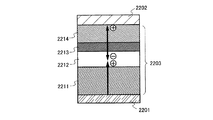
すなわち本発明の構成は、一対の電極間に、発光物質を含む層を有し、前記発光物質を含む層は、有機化合物と、バインダー物質と、前記有機化合物に対し電子供与性を示す無機化合物とを含む層を有していることを特徴とする発光素子である。 That is, the structure of the present invention includes a layer containing a luminescent substance between a pair of electrodes, and the layer containing the luminescent substance is an organic compound, a binder substance, and an inorganic compound that exhibits an electron donating property to the organic compound. A light emitting element characterized by having a layer containing.
また、本発明の他の構成は、一対の電極間に、発光物質を含む層を有し、前記発光物質を含む層のうち、前記一対の電極の一方の電極に接する層は、有機化合物と、バインダー物質と、前記有機化合物に対し電子供与性を示す無機化合物とを含むことを特徴とする発光素子である。 Another structure of the present invention includes a layer containing a light-emitting substance between a pair of electrodes, and of the layers containing the light-emitting substance, the layer in contact with one electrode of the pair of electrodes is an organic compound. A light emitting device comprising: a binder material; and an inorganic compound exhibiting an electron donating property to the organic compound.
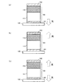
また、本発明の他の構成は、一対の電極間に、発光物質を含む層を有し、前記発光物質を含む層は、順次積層された第1の層、第2の層、第3の層で構成され、前記第1の層は、発光性の物質を含み、前記第2の層は、有機化合物と、バインダー物質と、前記有機化合物に対し電子供与性を示す無機化合物とを含み、前記第3の層は、ホールを発生する材料を含んでいる発光素子である。 Another structure of the present invention includes a layer containing a light-emitting substance between a pair of electrodes, and the layer containing the light-emitting substance includes a first layer, a second layer, and a third layer, which are sequentially stacked. The first layer includes a light emitting substance, the second layer includes an organic compound, a binder substance, and an inorganic compound that exhibits an electron donating property to the organic compound, The third layer is a light emitting element including a material that generates holes.
また、本発明の他の構成は、一対の電極間に、発光物質を含む層を有し、前記発光物質を含む層は、高分子化合物である有機化合物と、前記有機化合物に対し電子供与性を示す無機化合物とを含む層を有していることを特徴とする発光素子である。 Another structure of the present invention includes a layer containing a light-emitting substance between a pair of electrodes, and the layer containing the light-emitting substance has an organic compound that is a polymer compound and an electron donating property to the organic compound. A light-emitting element characterized by having a layer containing an inorganic compound.
また、本発明の他の構成は、一対の電極間に、発光物質を含む層を有し、前記発光物質を含む層のうち、前記一対の電極の一方の電極に接する層は、高分子化合物である有機化合物と、前記有機化合物に対し電子供与性を示す無機化合物とを含むことを特徴とする発光素子である。 Another structure of the present invention includes a layer containing a light-emitting substance between a pair of electrodes, and the layer in contact with one electrode of the pair of electrodes among the layers containing the light-emitting substance is a polymer compound. A light-emitting element comprising: an organic compound that is an inorganic compound that exhibits an electron donating property to the organic compound.
また、本発明の他の構成は、一対の電極間に、発光物質を含む層を有し、前記発光物質を含む層は、順次積層された第1の層、第2の層、第3の層で構成され、前記第1の層は、発光性の物質を含み、前記第2の層は、高分子化合物である有機化合物と、前記有機化合物に対し電子供与性を示す無機化合物とを含み、前記第3の層は、ホールを発生する材料を含んでいる発光素子である。 Another structure of the present invention includes a layer containing a light-emitting substance between a pair of electrodes, and the layer containing the light-emitting substance includes a first layer, a second layer, and a third layer, which are sequentially stacked. The first layer includes a light-emitting substance, and the second layer includes an organic compound that is a polymer compound and an inorganic compound that exhibits an electron donating property with respect to the organic compound. The third layer is a light-emitting element containing a material that generates holes.
なお、上述した本発明の発光素子において、前記バインダー物質は、ポリビニルアルコール、ポリメチルメタクリレート、ポリカーボネート、フェノール樹脂のいずれかであることが好ましい。また、前記有機化合物は、ピリジン骨格、イミダゾール骨格、トリアゾール骨格、オキサジアゾール骨格、チアジアゾール骨格、オキサゾール骨格、チアゾール骨格のいずれか一若しくは複数を有することが好ましい。また、前記無機化合物は、アルカリ金属またはアルカリ土類金属を含む酸化物であることが好ましく、特にリチウム酸化物、カルシウム酸化物、バリウム酸化物のいずれか一種もしくは複数種が好適である。 In the light-emitting element of the present invention described above, the binder material is preferably any one of polyvinyl alcohol, polymethyl methacrylate, polycarbonate, and phenol resin. The organic compound preferably has one or more of a pyridine skeleton, an imidazole skeleton, a triazole skeleton, an oxadiazole skeleton, a thiadiazole skeleton, an oxazole skeleton, and a thiazole skeleton. The inorganic compound is preferably an oxide containing an alkali metal or an alkaline earth metal, and in particular, one or more of lithium oxide, calcium oxide, and barium oxide are suitable.
さらに、上述したような発光素子を有する発光装置に関しても、本発明の一態様として含むものとする。なお、本発明における発光装置とは、発光素子を用いた画像表示デバイスもしくは発光体も含む。また、発光素子にコネクター、例えばFPC(Flexible Printed Circuit)もしくはTAB(Tape Automated Bonding)テープもしくはTCP(Tape Carrier Package)が取り付けられたモジュール、TABテープやTCPの先にプリント配線板が設けられたモジュール、または発光素子にCOG(Chip On Glass)方式によりIC(集積回路)が直接実装されたモジュールも全て発光装置の範疇に含むものとする。 Furthermore, a light-emitting device including the above-described light-emitting element is also included as one embodiment of the present invention. Note that the light emitting device in the present invention includes an image display device or a light emitter using a light emitting element. In addition, a module in which a connector such as an FPC (Flexible Printed Circuit) or TAB (Tape Automated Bonding) tape or TCP (Tape Carrier Package) is attached to the light emitting element, or a TAB tape or a module provided with a printed wiring board at the end of TCP In addition, a module in which an IC (integrated circuit) is directly mounted on a light emitting element by a COG (Chip On Glass) method is included in the category of the light emitting device.
ところで、本発明の発光素子を形成する作製方法も新規な概念に基づいており、本発明の一態様である。本発明では、上述した本発明の発光素子を作製する際に、有機化合物と、前記有機化合物に対して電子供与性を示す無機化合物とを含む層を、湿式法にて形成することを特徴としている。また、第1の電極から形成する手法と、第2の電極から形成する手法が考えられる。 By the way, a manufacturing method for forming the light-emitting element of the present invention is also based on a novel concept and is one embodiment of the present invention. In the present invention, when the above-described light-emitting element of the present invention is manufactured, a layer including an organic compound and an inorganic compound that exhibits an electron donating property with respect to the organic compound is formed by a wet method. Yes. A method of forming from the first electrode and a method of forming from the second electrode are conceivable.
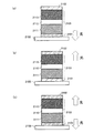
したがって本発明の構成は、第1の電極上に、発光物質を含む第1の層を形成する工程と、前記第1の層上に、有機化合物と、前記有機化合物に対し電子供与性を示す無機化合物とを含む第2の層を、湿式法により形成する工程と、前記第2の層上に、第2の電極を形成する工程とを有する発光素子の作製方法である。 Therefore, the structure of the present invention shows a step of forming a first layer containing a light-emitting substance on the first electrode, an organic compound on the first layer, and an electron donating property to the organic compound. It is a method for manufacturing a light-emitting element, which includes a step of forming a second layer containing an inorganic compound by a wet method and a step of forming a second electrode on the second layer.
また、本発明の他の構成は、第2の電極上に、有機化合物と、前記有機化合物に対し電子供与性を示す無機化合物とを含む第2の層を、湿式法により形成する工程と、前記第2の層上に、発光物質を含む第1の層を形成する工程と、前記第1の層上に、第1の電極を形成する工程とを有する発光素子の作製方法である。 According to another aspect of the present invention, there is provided a step of forming, on a second electrode, a second layer containing an organic compound and an inorganic compound having an electron donating property with respect to the organic compound by a wet method; A method for manufacturing a light-emitting element, which includes a step of forming a first layer containing a light-emitting substance over the second layer and a step of forming a first electrode over the first layer.
また、本発明の他の構成は、第1の電極上に、発光物質を含む第1の層を形成する工程と、前記第1の層上に、有機化合物と、前記有機化合物に対し電子供与性を示す無機化合物とを含む第2の層を、湿式法により形成する工程と、前記第2の層上に、ホールを発生する第3の層を形成する工程と、前記第3の層上に、第2の電極を形成する工程とを有する発光素子の作製方法である。 According to another configuration of the present invention, a step of forming a first layer containing a light-emitting substance on the first electrode, an organic compound on the first layer, and electron donation to the organic compound Forming a second layer containing an inorganic compound exhibiting properties by a wet method, forming a third layer generating holes on the second layer, and on the third layer And a step of forming a second electrode.
また、本発明の他の構成は、第2の電極上に、ホールを発生する第3の層を形成する工程と、前記第3の層上に、有機化合物と、前記有機化合物に対し電子供与性を示す無機化合物とを含む第2の層を、湿式法により形成する工程と、前記第2の層上に、発光物質を含む第1の層を形成する工程と、前記第1の層上に、第1の電極を形成する工程とを有する発光素子の作製方法である。 In another configuration of the present invention, a step of forming a third layer for generating holes on the second electrode, an organic compound on the third layer, and electron donation to the organic compound are provided. Forming a second layer containing an inorganic compound exhibiting properties by a wet method, forming a first layer containing a light-emitting substance on the second layer, and on the first layer And a step of forming a first electrode.
なお、上述した発光素子の作製方法において、第2の層は、金属のアルコキシドと有機化合物とを含む溶液を塗布、焼成することにより形成することができる。この時、水分による加水分解を行うと好ましいため、焼成する前に塗布膜を水蒸気にさらしてもよい。 Note that in the above method for manufacturing a light-emitting element, the second layer can be formed by applying and baking a solution containing a metal alkoxide and an organic compound. At this time, since it is preferable to perform hydrolysis with moisture, the coating film may be exposed to water vapor before baking.
したがって本発明の構成は、上述した発光素子の作製方法において、前記第2の層を形成する工程が、金属のアルコキシドと、有機化合物とを含む溶液を、塗布、焼成する工程であるか、または、金属のアルコキシドと、有機化合物とを含む溶液を塗布し、水蒸気にさらした後、焼成する工程であることを特徴とする発光素子の作製方法である。 Therefore, in the structure of the present invention, in the method for manufacturing a light-emitting element, the step of forming the second layer is a step of applying and baking a solution containing a metal alkoxide and an organic compound, or A method for manufacturing a light-emitting element, which is a step of applying a solution containing a metal alkoxide and an organic compound, exposing to water vapor, and baking.
なお、上述したような金属のアルコキシドを用いる手法の場合、前記溶液は、沈殿を防ぐための安定化剤をさらに含んでいてもよい。安定化剤としては、アセチルアセトン、アセト酢酸エチル、ベンゾイルアセトン等のβ−ジケトンが好適である。また、上述した溶液は、水分による金属のアルコキシドの加水分解を促進させるため、水をさらに含んでいてもよい。また、上述した溶液は、バインダー物質をさらに含んでいてもよく、バインダー物質としては、ポリビニルアルコール、ポリメチルメタクリレート、ポリカーボネート、またはフェノール樹脂が好適である。 In the case of the technique using the metal alkoxide as described above, the solution may further contain a stabilizer for preventing precipitation. As the stabilizer, β-diketones such as acetylacetone, ethyl acetoacetate, and benzoylacetone are suitable. Moreover, in order to accelerate | stimulate the hydrolysis of the metal alkoxide by a water | moisture content, the solution mentioned above may further contain water. The above-described solution may further contain a binder substance, and as the binder substance, polyvinyl alcohol, polymethyl methacrylate, polycarbonate, or phenol resin is preferable.
さらに、上述した本発明の発光素子の作製方法において、前記有機化合物は、ピリジン骨格、イミダゾール骨格、トリアゾール骨格、オキサジアゾール骨格、チアジアゾール骨格、オキサゾール骨格、チアゾール骨格のいずれか一若しくは複数が好ましい。 Furthermore, in the above-described method for manufacturing a light-emitting element of the present invention, the organic compound is preferably one or more of a pyridine skeleton, an imidazole skeleton, a triazole skeleton, an oxadiazole skeleton, a thiadiazole skeleton, an oxazole skeleton, and a thiazole skeleton.
また、本発明の発光素子の作製方法により、前記金属のアルコキシドを原料として、電子供与性の高い金属酸化物が形成される。したがって、前記金属は、アルカリ金属またはアルカリ土類金属が好ましい。中でも特に、リチウム、カルシウム、バリウムが好適である。 In addition, according to the method for manufacturing a light-emitting element of the present invention, a metal oxide having a high electron donating property is formed using the metal alkoxide as a raw material. Therefore, the metal is preferably an alkali metal or an alkaline earth metal. Of these, lithium, calcium, and barium are particularly preferable.
また、本発明者らは、有機化合物と、前記有機化合物に対して電子受容性を有する無機化合物とを含む複合材料を、発光素子に適用することで、課題を解決できることを見出した。特に、発光素子を作製する際に、前記複合材料を湿式法で形成することで、課題を解決できることを見出した。なお、前記複合材料を含む層を、発光素子の電極に接する位置に設けることで、発光素子の駆動電圧を低減することができる。あるいはまた、電子を発生する材料を含む層と、本発明の複合材料を含む層とを積層した構造を、発光素子の電極に接する位置に設けることで、発光素子の駆動電圧を低減することができる。 The present inventors have also found that the problem can be solved by applying a composite material including an organic compound and an inorganic compound having an electron accepting property to the organic compound to a light-emitting element. In particular, when manufacturing a light emitting element, it discovered that a subject could be solved by forming the said composite material with a wet method. Note that the driving voltage of the light-emitting element can be reduced by providing the layer including the composite material at a position in contact with the electrode of the light-emitting element. Alternatively, the driving voltage of the light-emitting element can be reduced by providing a structure in which a layer including a material that generates electrons and a layer including the composite material of the present invention is stacked at a position in contact with the electrode of the light-emitting element. it can.
また、本発明においては、湿式法により成膜する時の膜質を考慮し、前記有機化合物が低分子化合物の場合は、前記複合材料はバインダーとなる材料(以下、バインダー物質)をさらに含む。また、前記有機化合物が高分子化合物(本明細書中においては、ポリマーだけでなく、オリゴマーやデンドリマー等の中程度の分子量の化合物も含む)の場合は、前記複合材料はバインダー物質をさらに含んでいても良いが、必ずしも必要ではない。 In the present invention, in consideration of the film quality when the film is formed by a wet method, when the organic compound is a low molecular compound, the composite material further includes a material to be a binder (hereinafter referred to as a binder substance). When the organic compound is a high molecular compound (in this specification, not only a polymer but also a medium molecular weight compound such as an oligomer or a dendrimer), the composite material further includes a binder substance. It may be, but is not necessary.
したがって本発明の構成は、一対の電極間に、発光物質を含む層を有し、前記発光物質を含む層は、有機化合物と、バインダー物質と、前記有機化合物に対し電子受容性を示す無機化合物とを含む層を有していることを特徴とする発光素子である。 Therefore, the structure of the present invention includes a layer containing a light emitting substance between a pair of electrodes, and the layer containing the light emitting substance includes an organic compound, a binder substance, and an inorganic compound that exhibits electron acceptability with respect to the organic compound. A light emitting element characterized by having a layer containing.
また、本発明の他の構成は、一対の電極間に、発光物質を含む層を有し、前記発光物質を含む層のうち、前記一対の電極の一方の電極に接する層は、有機化合物と、バインダー物質と、前記有機化合物に対し電子受容性を示す無機化合物とを含むことを特徴とする発光素子である。 Another structure of the present invention includes a layer containing a light-emitting substance between a pair of electrodes, and of the layers containing the light-emitting substance, the layer in contact with one electrode of the pair of electrodes is an organic compound. A light emitting device comprising: a binder material; and an inorganic compound having an electron accepting property with respect to the organic compound.
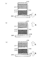
また、本発明の他の構成は、一対の電極間に、発光物質を含む層を有し、前記発光物質を含む層は、順次積層された第1の層、第2の層、第3の層、第4の層で構成され、前記第1の層は、有機化合物と、バインダー物質と、前記有機化合物に対し電子受容性を示す無機化合物とを含む複合材料を含み、前記第2の層は、発光性の物質を含み、前記第3の層は、電子を発生する材料を含み、前記第4の層は、ホールを発生する材料を含んでいる発光素子である。なお、この時、第4の層は、本発明の複合材料を用いて形成することもできる。 Another structure of the present invention includes a layer containing a light-emitting substance between a pair of electrodes, and the layer containing the light-emitting substance includes a first layer, a second layer, and a third layer, which are sequentially stacked. The first layer includes a composite material including an organic compound, a binder substance, and an inorganic compound that exhibits an electron accepting property with respect to the organic compound, and the second layer. Includes a light-emitting substance, the third layer includes a material that generates electrons, and the fourth layer includes a material that generates holes. At this time, the fourth layer can also be formed using the composite material of the present invention.
また、本発明の他の構成は、一対の電極間に、発光物質を含む層を有し、前記発光物質を含む層は、順次積層された第1の層、第2の層、第3の層、第4の層で構成され、前記第1の層は、ホールを発生する材料を含み、前記第2の層は、発光性の物質を含み、前記第3の層は、電子を発生する材料を含み、前記第4の層は、有機化合物と、バインダー物質と、前記有機化合物に対し電子受容性を示す無機化合物とを含む複合材料を含んでいる発光素子である。 Another structure of the present invention includes a layer containing a light-emitting substance between a pair of electrodes, and the layer containing the light-emitting substance includes a first layer, a second layer, and a third layer, which are sequentially stacked. The first layer includes a material that generates holes, the second layer includes a light-emitting substance, and the third layer generates electrons. The fourth layer is a light-emitting element including a composite material including an organic compound, a binder substance, and an inorganic compound having an electron accepting property with respect to the organic compound.
また、本発明の他の構成は、一対の電極間に、発光物質を含む層を有し、前記発光物質を含む層は、高分子化合物である有機化合物と、前記有機化合物に対し電子受容性を示す無機化合物とを含む層を有していることを特徴とする発光素子である。 Another structure of the present invention includes a layer containing a light-emitting substance between a pair of electrodes, and the layer containing the light-emitting substance has an organic compound that is a polymer compound and an electron-accepting property for the organic compound A light-emitting element characterized by having a layer containing an inorganic compound.
また、本発明の他の構成は、一対の電極間に、発光物質を含む層を有し、前記発光物質を含む層のうち、前記一対の電極の一方の電極に接する層は、高分子化合物である有機化合物と、前記有機化合物に対し電子受容性を示す無機化合物とを含むことを特徴とする発光素子である。 Another structure of the present invention includes a layer containing a light-emitting substance between a pair of electrodes, and the layer in contact with one electrode of the pair of electrodes among the layers containing the light-emitting substance is a polymer compound. A light-emitting element comprising: an organic compound that is: and an inorganic compound that exhibits an electron accepting property with respect to the organic compound.
また、本発明の他の構成は、一対の電極間に、発光物質を含む層を有し、前記発光物質を含む層は、順次積層された第1の層、第2の層、第3の層、第4の層で構成され、前記第1の層は、高分子化合物である有機化合物と、前記有機化合物に対し電子受容性を示す無機化合物とを含む複合材料を含み、前記第2の層は、発光性の物質を含み、前記第3の層は、電子を発生する材料を含み、前記第4の層は、ホールを発生する材料を含んでいる発光素子である。なお、この時、第4の層は、本発明の複合材料を用いて形成することもできる。 Another structure of the present invention includes a layer containing a light-emitting substance between a pair of electrodes, and the layer containing the light-emitting substance includes a first layer, a second layer, and a third layer, which are sequentially stacked. The first layer includes a composite material including an organic compound that is a high molecular compound and an inorganic compound that exhibits an electron accepting property with respect to the organic compound, and the second layer. The layer includes a light-emitting substance, the third layer includes a material that generates electrons, and the fourth layer includes a material that generates holes. At this time, the fourth layer can also be formed using the composite material of the present invention.
また、本発明の他の構成は、一対の電極間に、発光物質を含む層を有し、前記発光物質を含む層は、順次積層された第1の層、第2の層、第3の層、第4の層で構成され、前記第1の層は、ホールを発生する材料を含み、前記第2の層は、発光性の物質を含み、前記第3の層は、電子を発生する材料を含み、前記第4の層は、高分子化合物である有機化合物と、前記有機化合物に対し電子受容性を示す無機化合物とを含む複合材料を含んでいる発光素子である。 Another structure of the present invention includes a layer containing a light-emitting substance between a pair of electrodes, and the layer containing the light-emitting substance includes a first layer, a second layer, and a third layer, which are sequentially stacked. The first layer includes a material that generates holes, the second layer includes a light-emitting substance, and the third layer generates electrons. The fourth layer is a light-emitting element including a composite material including an organic compound that is a polymer compound and an inorganic compound that exhibits an electron accepting property with respect to the organic compound.
なお、上述した本発明の発光素子において、前記バインダー物質は、ポリビニルアルコール、ポリメチルメタクリレート、ポリカーボネート、またはフェノール樹脂のいずれかが好ましい。 In the light-emitting element of the present invention described above, the binder substance is preferably any of polyvinyl alcohol, polymethyl methacrylate, polycarbonate, or phenol resin.
また、前記有機化合物としては、アリールアミン骨格を有することが好ましい。あるいはまた、下記に示す一般式(1)〜(10)のいずれかの高分子化合物であることが好ましい。 Further, the organic compound preferably has an arylamine skeleton. Or it is preferable that it is a high molecular compound in any one of General formula (1)-(10) shown below.

さらに、上述した発光素子において、前記無機化合物は、遷移金属を含む酸化物であることが好ましく、中でも特に、チタン酸化物、バナジウム酸化物、モリブデン酸化物、タングステン酸化物、レニウム酸化物、ルテニウム酸化物が好適である。 Further, in the above light-emitting element, the inorganic compound is preferably an oxide containing a transition metal, and in particular, titanium oxide, vanadium oxide, molybdenum oxide, tungsten oxide, rhenium oxide, ruthenium oxide. Things are preferred.
なお、上述したような発光素子を有する発光装置に関しても、本発明の一態様として含むものとする。なお、本発明における発光装置とは、発光素子を用いた画像表示デバイスもしくは発光体を含む。また、発光素子にコネクター、例えばFPC(Flexible Printed Circuit)もしくはTAB(Tape Automated Bonding)テープもしくはTCP(Tape Carrier Package)が取り付けられたモジュール、TABテープやTCPの先にプリント配線板が設けられたモジュール、または発光素子にCOG(Chip On Glass)方式によりIC(集積回路)が直接実装されたモジュールも全て発光装置の範疇に含むものとする。 Note that a light-emitting device including the above-described light-emitting element is also included as one embodiment of the present invention. Note that the light emitting device in the present invention includes an image display device using a light emitting element or a light emitter. In addition, a module in which a connector such as an FPC (Flexible Printed Circuit) or TAB (Tape Automated Bonding) tape or TCP (Tape Carrier Package) is attached to the light emitting element, or a TAB tape or a module provided with a printed wiring board at the end of TCP In addition, a module in which an IC (integrated circuit) is directly mounted on a light emitting element by a COG (Chip On Glass) method is included in the category of the light emitting device.
ところで、本発明の発光素子を形成する作製方法も新規な概念に基づいており、本発明の一態様である。本発明では、上述したような有機化合物と、前記有機化合物に対して電子受容性を示す無機化合物とを含む複合材料を、湿式法にて形成することを特徴としている。また、第1の電極から形成する手法と、第2の電極から形成する手法が考えられる。 By the way, a manufacturing method for forming the light-emitting element of the present invention is also based on a novel concept and is one embodiment of the present invention. In the present invention, a composite material including the organic compound as described above and an inorganic compound exhibiting an electron accepting property with respect to the organic compound is formed by a wet method. A method of forming from the first electrode and a method of forming from the second electrode are conceivable.
すなわち本発明の構成は、第1の電極上に、有機化合物と、前記有機化合物に対し電子受容性を示す無機化合物とを含む第1の層を、湿式法により形成する工程と、前記第1の層上に発光物質を含む第2の層を形成する工程と、前記第2の層上に、第2の電極を形成する工程とを有する発光素子の作製方法である。 That is, the configuration of the present invention includes a step of forming, on a first electrode, a first layer containing an organic compound and an inorganic compound having an electron accepting property with respect to the organic compound by a wet method; A method for manufacturing a light-emitting element, which includes a step of forming a second layer containing a light-emitting substance on the first layer and a step of forming a second electrode on the second layer.
また、本発明の他の構成は、第2の電極上に、発光物質を含む第2の層を形成する工程と、前記第2の層上に、有機化合物と、前記有機化合物に対し電子受容性を示す無機化合物とを含む第1の層を、湿式法により形成する工程と、前記第1の層上に、第1の電極を形成する工程とを有する発光素子の作製方法である。 According to another configuration of the present invention, a step of forming a second layer containing a light-emitting substance on the second electrode, an organic compound on the second layer, and an electron acceptance for the organic compound A method for manufacturing a light-emitting element including a step of forming a first layer containing an inorganic compound exhibiting properties by a wet method and a step of forming a first electrode on the first layer.
また、本発明の他の構成は、第1の電極上に、有機化合物と、前記有機化合物に対し電子受容性を示す無機化合物とを含む第1の層を、湿式法により形成する工程と、前記第1の層上に、発光物質を含む第2の層を形成する工程と、前記第2の層上に、電子を発生する材料を含む第3の層を形成する工程と、前記第3の層上に、ホールを発生する材料を含む第4の層を形成する工程と、前記第4の層上に、第2の電極を形成する工程とを有する発光素子の作製方法である。なお、第4の層は第1の層と同様に湿式法によって形成されていてもよいし、蒸着法などの他の方法により形成されていてもよい。 According to another aspect of the present invention, there is provided a step of forming, on a first electrode, a first layer containing an organic compound and an inorganic compound having an electron accepting property with respect to the organic compound by a wet method; Forming a second layer containing a light-emitting substance on the first layer, forming a third layer containing a material that generates electrons on the second layer, and the third layer. A method for manufacturing a light-emitting element including a step of forming a fourth layer containing a material that generates holes on the layer and a step of forming a second electrode on the fourth layer. Note that the fourth layer may be formed by a wet method similarly to the first layer, or may be formed by another method such as an evaporation method.
また、本発明の他の構成は、第2の電極上に、ホールを発生する材料を含む第4の層を形成する工程と、前記第4の層上に、電子を発生する材料を含む第3の層を形成する工程と、前記第3の層上に、発光物質を含む第2の層を形成する工程と、前記第2の層上に、有機化合物と、前記有機化合物に対し電子供与性を示す無機化合物とを含む第1の層を、湿式法により形成する工程と、前記第1の層上に、第1の電極を形成する工程とを有する発光素子の作製方法である。なお、第4の層は第1の層と同様に湿式法によって形成されていてもよいし、蒸着法などの他の方法により形成されていてもよい。 In another configuration of the present invention, a step of forming a fourth layer including a material that generates holes on the second electrode, and a step of including a material that generates electrons on the fourth layer are provided. Forming a third layer, forming a second layer containing a light-emitting substance on the third layer, an organic compound on the second layer, and donating electrons to the organic compound A method for manufacturing a light-emitting element including a step of forming a first layer containing an inorganic compound exhibiting properties by a wet method and a step of forming a first electrode on the first layer. Note that the fourth layer may be formed by a wet method similarly to the first layer, or may be formed by another method such as an evaporation method.
また、本発明の他の構成は、第1の電極上に、ホールを発生する材料を含む第1の層を形成する工程と、前記第1の層上に、発光物質を含む第2の層を形成する工程と、前記第2の層上に、電子を発生する材料を含む第3の層を形成する工程と、前記第3の層上に、有機化合物と、前記有機化合物に対し電子受容性を示す無機化合物とを含む第4の層を、湿式法により形成する工程と、前記第4の層上に、第2の電極を形成する工程とを有する発光素子の作製方法である。なお、第1の層は第4の層と同様に湿式法によって形成されていてもよいし、蒸着法などの他の方法により形成されていてもよい。 According to another aspect of the present invention, there is provided a step of forming a first layer containing a material that generates holes on the first electrode, and a second layer containing a luminescent material on the first layer. Forming a third layer containing a material for generating electrons on the second layer, an organic compound on the third layer, and accepting electrons to the organic compound The light-emitting element manufacturing method includes a step of forming a fourth layer containing an inorganic compound exhibiting properties by a wet method and a step of forming a second electrode on the fourth layer. In addition, the 1st layer may be formed by the wet method similarly to the 4th layer, and may be formed by other methods, such as a vapor deposition method.
また、本発明の他の構成は、第2の電極上に、有機化合物と、前記有機化合物に対し電子供与性を示す無機化合物を含む第4の層を、湿式法により形成する工程と、前記第4の層上に、電子を発生する材料を含む第3の層を形成する工程と、前記第3の層上に、発光物質を含む第2の層を形成する工程と、前記第2の層上に、ホールを発生する材料を含む第1の層を形成する工程と、前記第1の層上に、第1の電極を形成する工程とを有する発光素子の作製方法である。なお、第1の層は第4の層と同様に湿式法によって形成されていてもよいし、蒸着法などの他の方法により形成されていてもよい。 In addition, another configuration of the present invention includes a step of forming, on a second electrode, a fourth layer containing an organic compound and an inorganic compound that exhibits an electron donating property with respect to the organic compound by a wet method, Forming a third layer containing a material that generates electrons on the fourth layer; forming a second layer containing a light-emitting substance on the third layer; and A method for manufacturing a light-emitting element, which includes a step of forming a first layer containing a material that generates holes on a layer and a step of forming a first electrode on the first layer. In addition, the 1st layer may be formed by the wet method similarly to the 4th layer, and may be formed by other methods, such as a vapor deposition method.
なお、上述した発光素子の作製方法において、第1の層、及び第4の層は、それぞれ、金属のアルコキシドと有機化合物とを含む溶液を塗布、焼成することにより形成することができる。この時、水分による加水分解を行うと好ましいため、焼成する前に塗布膜を水蒸気にさらしてもよい。 Note that in the above method for manufacturing a light-emitting element, the first layer and the fourth layer can be formed by applying and baking a solution containing a metal alkoxide and an organic compound, respectively. At this time, since it is preferable to perform hydrolysis with moisture, the coating film may be exposed to water vapor before baking.
したがって、本発明の構成は、上述した発光素子の作製方法において、第1の層を形成する工程が、金属のアルコキシドと、有機化合物とを含む溶液を、塗布、焼成する工程であるか、または、金属のアルコキシドと、有機化合物とを含む溶液を塗布し、水蒸気にさらした後、焼成する工程であることを特徴とする発光素子の作製方法である。 Therefore, in the structure of the present invention, in the method for manufacturing a light-emitting element described above, the step of forming the first layer is a step of applying and baking a solution containing a metal alkoxide and an organic compound, or A method for manufacturing a light-emitting element, which is a step of applying a solution containing a metal alkoxide and an organic compound, exposing to water vapor, and baking.
また、本発明の他の構成は、第4の層を形成する工程が、金属のアルコキシドと、有機化合物とを含む溶液を、塗布、焼成する工程であるか、または、金属のアルコキシドと、有機化合物とを含む溶液を塗布し、水蒸気にさらした後、焼成する工程であることを特徴とする発光素子の作製方法である。 In another configuration of the present invention, the step of forming the fourth layer is a step of applying and baking a solution containing a metal alkoxide and an organic compound, or a metal alkoxide and an organic layer. A method for manufacturing a light-emitting element, which is a step of applying a solution containing a compound, exposing to water vapor, and baking.
なお、上述したような金属のアルコキシドを用いる手法の場合、前記溶液は、沈殿を防ぐための安定化剤をさらに含んでいてもよい。安定化剤としては、アセチルアセトン、アセト酢酸エチル、ベンゾイルアセトン等のβ−ジケトンが好適である。また、金属のアルコキシドの加水分解を促進させるため、上述した溶液は水をさらに含んでいてもよい。 In the case of the technique using the metal alkoxide as described above, the solution may further contain a stabilizer for preventing precipitation. As the stabilizer, β-diketones such as acetylacetone, ethyl acetoacetate, and benzoylacetone are suitable. Moreover, in order to accelerate | stimulate hydrolysis of a metal alkoxide, the solution mentioned above may further contain water.
さらに、第1の層および第4の層は、上述したような金属のアルコキシドを用いる手法だけでなく、金属の水酸化物を原料として形成することもできる。この場合、沈殿が生じにくいというメリットや、加水分解を行わなくても酸化物を形成する反応が起きやすいというメリットがある。 Further, the first layer and the fourth layer can be formed not only by using the metal alkoxide as described above but also by using a metal hydroxide as a raw material. In this case, there is a merit that precipitation is difficult to occur and a reaction for forming an oxide easily occurs without hydrolysis.
したがって本発明の他の構成は、上述した発光素子の作製方法において、前記第1の層を形成する工程が、金属の水酸化物を解膠することにより得られたゾルと、有機化合物とを含む溶液を、塗布、焼成する工程であることを特徴とする発光素子の作製方法である。 Therefore, another structure of the present invention is the above-described method for manufacturing a light-emitting element, in which the step of forming the first layer includes a sol obtained by peptizing a metal hydroxide and an organic compound. A method for manufacturing a light-emitting element, which is a step of applying and baking a solution containing the light-emitting element.
また、本発明の他の構成は、上述した発光素子の作製方法において、前記第4の層を形成する工程が、金属の水酸化物を解膠することにより得られたゾルと、有機化合物とを含む溶液を、塗布、焼成する工程であることを特徴とする発光素子の作製方法である。 In addition, according to another configuration of the present invention, in the above-described method for manufacturing a light-emitting element, the step of forming the fourth layer includes a sol obtained by peptizing a metal hydroxide, an organic compound, A method for manufacturing a light-emitting element, which is a step of applying and baking a solution containing the above.
なお、以上で述べた発光素子の作製方法において、前記溶液は、バインダー物質をさらに含んでいてもよい。バインダー物質としては、ポリビニルアルコール、ポリメチルメタクリレート、ポリカーボネート、またはフェノール樹脂が好適である。 Note that in the above-described method for manufacturing a light-emitting element, the solution may further include a binder substance. As the binder material, polyvinyl alcohol, polymethyl methacrylate, polycarbonate, or phenol resin is preferable.
また、上述した発光素子の作製方法において、前記有機化合物は、アリールアミン骨格を有することが好ましい。あるいはまた、先に述べた一般式(1)〜(10)のいずれかで表される高分子化合物であることが好ましい。 In the above method for manufacturing a light-emitting element, the organic compound preferably has an arylamine skeleton. Alternatively, it is preferably a polymer compound represented by any one of the general formulas (1) to (10) described above.
また、本発明の発光素子の作製方法により、第1の金属のアルコキシドや、解膠により得られる第1の金属の水酸化物を原料として、電子受容性の高い金属酸化物が形成される。したがって、上述した発光素子の作製方法において、前記金属は遷移金属であることが好ましい。中でも特に、チタン、バナジウム、モリブデン、タングステン、レニウム、ルテニウムが好適である。 In addition, according to the method for manufacturing a light-emitting element of the present invention, a metal oxide having high electron-accepting property is formed using a first metal alkoxide or a first metal hydroxide obtained by peptization. Therefore, in the above method for manufacturing a light-emitting element, the metal is preferably a transition metal. Among these, titanium, vanadium, molybdenum, tungsten, rhenium, and ruthenium are particularly preferable.
また、本発明者らは、第1の有機化合物および第1の有機化合物に対して電子受容性を有する第1の無機化合物を含む第1の複合材料と、第2の有機化合物および第2の有機化合物に対して電子供与性を有する第2の無機化合物を含む第2の複合材料とで、発光性の物質を含む層を挟んだ構成の発光素子を作製することで、課題を解決できることを見出した。特に、発光素子を作製する際に、第1の複合材料および第2の複合材料の双方を湿式法で形成することで、課題を解決できることを見出した。 The present inventors also include a first composite material including a first organic compound and a first inorganic compound having an electron accepting property with respect to the first organic compound, a second organic compound, and a second organic compound. The problem can be solved by manufacturing a light-emitting element having a structure in which a layer containing a light-emitting substance is sandwiched between a second composite material containing a second inorganic compound having an electron-donating property with respect to an organic compound. I found it. In particular, when manufacturing a light emitting element, it discovered that a subject could be solved by forming both the 1st composite material and the 2nd composite material with a wet method.
本発明においては、湿式法により成膜する時の膜質を考慮し、第1の有機化合物や第2の有機化合物が低分子化合物の場合は、第1の複合材料や第2の複合材料はバインダーとなる材料(以下、バインダー物質)をさらに含む。また、第1の有機化合物や第2の有機化合物が高分子化合物(本明細書中においては、ポリマーだけでなく、オリゴマーやデンドリマー等の中程度の分子量の化合物も含む)の場合は、第1の複合材料や第2の複合材料はバインダー物質をさらに含んでいても良いが、必ずしも必要ではない。 In the present invention, in consideration of the film quality when the film is formed by a wet method, when the first organic compound or the second organic compound is a low molecular compound, the first composite material or the second composite material is a binder. It further includes a material (hereinafter referred to as a binder substance). In the case where the first organic compound or the second organic compound is a high molecular compound (in this specification, not only a polymer but also a medium molecular weight compound such as an oligomer or a dendrimer is included) The composite material and the second composite material may further contain a binder substance, but are not necessarily required.
したがって本発明の構成は、一対の電極間に、発光物質を含む層を有し、前記発光物質を含む層は、順次積層された第1の層、第2の層、第3の層で構成され、前記第1の層は、第1の有機化合物と、第1のバインダー物質と、前記第1の有機化合物に対し電子受容性を示す第1の無機化合物とを含む第1の複合材料を含み、前記第2の層は、発光性の物質を含み、前記第3の層は、第2の有機化合物と、第2のバインダー物質と、前記第2の有機化合物に対し電子供与性を示す第2の無機化合物とを含む第2の複合材料を含んでいる発光素子である。 Therefore, the structure of the present invention has a layer containing a light emitting substance between a pair of electrodes, and the layer containing the light emitting substance is composed of a first layer, a second layer, and a third layer that are sequentially stacked. And the first layer includes a first composite material including a first organic compound, a first binder substance, and a first inorganic compound exhibiting an electron accepting property with respect to the first organic compound. And the second layer includes a light-emitting substance, and the third layer exhibits an electron donating property to the second organic compound, the second binder substance, and the second organic compound. The light-emitting element includes a second composite material including a second inorganic compound.
また、本発明の他の構成は、一対の電極間に、発光物質を含む層を有し、前記発光物質を含む層は、順次積層された第1の層、第2の層、第3の層で構成され、前記第1の層は、高分子化合物である第1の有機化合物と、前記第1の有機化合物に対し電子受容性を示す第1の無機化合物とを含む第1の複合材料を含み、前記第2の層は、発光性の物質を含み、前記第3の層は、第2の有機化合物と、バインダー物質と、前記第2の有機化合物に対し電子供与性を示す第2の無機化合物とを含む第2の複合材料を含んでいる発光素子である。 Another structure of the present invention includes a layer containing a light-emitting substance between a pair of electrodes, and the layer containing the light-emitting substance includes a first layer, a second layer, and a third layer, which are sequentially stacked. A first composite material comprising a first organic compound that is a polymer compound and a first inorganic compound that exhibits an electron accepting property with respect to the first organic compound. The second layer contains a light-emitting substance, and the third layer is a second organic compound, a binder substance, and a second material that exhibits an electron donating property to the second organic compound. The light emitting element containing the 2nd composite material containing these inorganic compounds.
また、本発明の他の構成は、一対の電極間に、発光物質を含む層を有し、前記発光物質を含む層は、順次積層された第1の層、第2の層、第3の層で構成され、前記第1の層は、第1の有機化合物と、バインダー物質と、前記第1の有機化合物に対し電子受容性を示す第1の無機化合物とを含む第1の複合材料を含み、前記第2の層は、発光性の物質を含み、前記第3の層は、高分子化合物である第2の有機化合物と、前記第2の有機化合物に対し電子供与性を示す第2の無機化合物とを含む第2の複合材料を含んでいる発光素子である。 Another structure of the present invention includes a layer containing a light-emitting substance between a pair of electrodes, and the layer containing the light-emitting substance includes a first layer, a second layer, and a third layer, which are sequentially stacked. The first layer includes a first composite material including a first organic compound, a binder substance, and a first inorganic compound that exhibits an electron accepting property with respect to the first organic compound. The second layer contains a light-emitting substance; the third layer includes a second organic compound that is a polymer compound; and a second organic compound that exhibits an electron donating property with respect to the second organic compound. The light emitting element containing the 2nd composite material containing these inorganic compounds.
また、本発明の他の構成は、一対の電極間に、発光物質を含む層を有し、前記発光物質を含む層は、順次積層された第1の層、第2の層、第3の層で構成され、前記第1の層は、高分子化合物である第1の有機化合物と、前記第1の有機化合物に対し電子受容性を示す第1の無機化合物とを含む第1の複合材料を含み、前記第2の層は、発光性の物質を含み、前記第3の層は、高分子化合物である第2の有機化合物と、前記第2の有機化合物に対し電子供与性を示す第2の無機化合物とを含む第2の複合材料を含んでいる発光素子である。 Another structure of the present invention includes a layer containing a light-emitting substance between a pair of electrodes, and the layer containing the light-emitting substance includes a first layer, a second layer, and a third layer, which are sequentially stacked. A first composite material comprising a first organic compound that is a polymer compound and a first inorganic compound that exhibits an electron accepting property with respect to the first organic compound. The second layer contains a light-emitting substance, the third layer is a second organic compound that is a high molecular compound, and a second organic compound that exhibits an electron donating property to the second organic compound. 2 is a light-emitting element including a second composite material including two inorganic compounds.
ここで、上述したバインダー物質としては、ポリビニルアルコール、ポリメチルメタクリレート、ポリカーボネート、またはフェノール樹脂であることが好ましい。また、第1の有機化合物は、アリールアミン骨格を有する化合物であることが好ましい。また、第2の有機化合物は、ピリジン骨格、イミダゾール骨格、トリアゾール骨格、オキサジアゾール骨格、チアジアゾール骨格、オキサゾール骨格、チアゾール骨格のいずれか一若しくは複数を有することが好ましい。 Here, the binder material described above is preferably polyvinyl alcohol, polymethyl methacrylate, polycarbonate, or phenol resin. The first organic compound is preferably a compound having an arylamine skeleton. The second organic compound preferably has one or more of a pyridine skeleton, an imidazole skeleton, a triazole skeleton, an oxadiazole skeleton, a thiadiazole skeleton, an oxazole skeleton, and a thiazole skeleton.
また、第1の無機化合物は電子受容性が高いことが求められるため、遷移金属を含む酸化物であることが好ましい。中でも特に、チタン酸化物、バナジウム酸化物、モリブデン酸化物、タングステン酸化物、レニウム酸化物、ルテニウム酸化物、は好適である。 Further, since the first inorganic compound is required to have a high electron accepting property, it is preferably an oxide containing a transition metal. Among these, titanium oxide, vanadium oxide, molybdenum oxide, tungsten oxide, rhenium oxide, and ruthenium oxide are particularly preferable.
一方、第2の無機化合物は電子供与性が高いことが求められ、アルカリ金属またはアルカリ土類金属を含む酸化物が好ましい。中でも特に、リチウム酸化物、カルシウム酸化物、バリウム酸化物は好適である。 On the other hand, the second inorganic compound is required to have a high electron donating property, and an oxide containing an alkali metal or an alkaline earth metal is preferable. Among these, lithium oxide, calcium oxide, and barium oxide are particularly preferable.
なお、上述した遷移金属を含む酸化物や、アルカリ金属またはアルカリ土類金属を含む酸化物は、水酸基を有していてもよい。 Note that the above-described oxide containing a transition metal or an oxide containing an alkali metal or an alkaline earth metal may have a hydroxyl group.
また、上述した本発明の発光素子において、前記発光物質を含む層が、さらに前記第3の層と接する第4の層を有し、前記第4の層は、第3の有機化合物と、前記第3の有機化合物に対し電子受容性を示す第3の無機化合物とを含む第3の複合材料を含んでいる発光素子も、本発明の構成の一つである。 In the above-described light-emitting element of the present invention, the layer containing the light-emitting substance further includes a fourth layer in contact with the third layer, and the fourth layer includes the third organic compound, A light-emitting element including a third composite material including a third inorganic compound that exhibits an electron accepting property with respect to the third organic compound is also one of the structures of the present invention.
この時、前記第3の有機化合物は、アリールアミン骨格を有することが好ましい。また、前記第3の無機化合物は、遷移金属を含む酸化物であることが好ましく、例えばチタン酸化物、バナジウム酸化物、モリブデン酸化物、タングステン酸化物、レニウム酸化物、ルテニウム酸化物が好適である。 At this time, the third organic compound preferably has an arylamine skeleton. The third inorganic compound is preferably an oxide containing a transition metal. For example, titanium oxide, vanadium oxide, molybdenum oxide, tungsten oxide, rhenium oxide, and ruthenium oxide are preferable. .
さらに、上述したような発光素子を有する発光装置に関しても、本発明の一態様として含むものとする。なお、本発明における発光装置とは、発光素子を用いた画像表示デバイスもしくは発光体を含む。また、発光素子にコネクター、例えばFPC(Flexible Printed Circuit)もしくはTAB(Tape Automated Bonding)テープもしくはTCP(Tape Carrier Package)が取り付けられたモジュール、TABテープやTCPの先にプリント配線板が設けられたモジュール、または発光素子にCOG(Chip On Glass)方式によりIC(集積回路)が直接実装されたモジュールも全て発光装置の範疇に含むものとする。 Furthermore, a light-emitting device including the above-described light-emitting element is also included as one embodiment of the present invention. Note that the light emitting device in the present invention includes an image display device using a light emitting element or a light emitter. In addition, a module in which a connector such as an FPC (Flexible Printed Circuit) or TAB (Tape Automated Bonding) tape or TCP (Tape Carrier Package) is attached to the light emitting element, or a TAB tape or a module provided with a printed wiring board at the end of TCP In addition, a module in which an IC (integrated circuit) is directly mounted on a light emitting element by a COG (Chip On Glass) method is included in the category of the light emitting device.
ところで、本発明の発光素子を形成する作製方法も新規な概念に基づいており、本発明の一態様である。本発明では、上述した第1の層、及び第3の層をそれぞれ湿式法にて形成することを特徴としている。また、第1の電極から形成する手法と、第2の電極から形成する手法が考えられる。 By the way, a manufacturing method for forming the light-emitting element of the present invention is also based on a novel concept and is one embodiment of the present invention. The present invention is characterized in that the first layer and the third layer described above are each formed by a wet method. A method of forming from the first electrode and a method of forming from the second electrode are conceivable.
すなわち本発明の構成は、第1の電極上に、第1の有機化合物と、前記第1の有機化合物に対し電子受容性を示す第1の無機化合物とを含む第1の層を、湿式法により形成する工程と、前記第1の層上に、発光性の物質を含む第2の層を形成する工程と、前記第2の層上に、第2の有機化合物と、前記第2の有機化合物に対し電子供与性を示す第2の無機化合物とを含む第3の層を、湿式法により形成する工程と、前記第3の層上に、第2の電極を形成する工程とを有する発光素子の作製方法である。 That is, according to the structure of the present invention, a first layer containing a first organic compound and a first inorganic compound exhibiting an electron accepting property with respect to the first organic compound is formed on a first electrode by a wet method. Forming a second layer containing a light-emitting substance on the first layer, a second organic compound on the second layer, and the second organic Luminescence having a step of forming a third layer containing a second inorganic compound exhibiting an electron donating property with respect to a compound by a wet method and a step of forming a second electrode on the third layer. This is a method for manufacturing an element.
また、本発明の他の構成は、第2の電極上に、第2の有機化合物と、前記第2の有機化合物に対し電子供与性を示す第2の無機化合物とを含む第3の層を、湿式法により形成する工程と、前記第3の層上に、発光性の物質を含む第2の層を形成する工程と、前記第2の層上に、第1の有機化合物と、前記第1の有機化合物に対し電子受容性を示す第1の無機化合物とを含む第1の層を、湿式法により形成する工程と、前記第1の層上に、第1の電極を形成する工程とを有する発光素子の作製方法である。 According to another configuration of the present invention, a third layer including a second organic compound and a second inorganic compound that exhibits an electron donating property to the second organic compound is provided on the second electrode. A step of forming by a wet method, a step of forming a second layer containing a light-emitting substance on the third layer, a first organic compound on the second layer, and the first layer Forming a first layer containing a first inorganic compound exhibiting electron accepting property with respect to one organic compound by a wet method, and forming a first electrode on the first layer; This is a method for manufacturing a light-emitting element having the above.
また、本発明の他の構成は、第1の電極上に、第1の有機化合物と、前記第1の有機化合物に対し電子受容性を示す第1の無機化合物とを含む第1の層を、湿式法により形成する工程と、前記第1の層上に、発光物質を含む第2の層を形成する工程と、前記第2の層上に、第2の有機化合物と、前記第2の有機化合物に対し電子供与性を示す第2の無機化合物とを含む第3の層を、湿式法により形成する工程と、前記第3の層上に、第3の有機化合物と、前記第3の有機化合物に対し電子受容性を示す第3の無機化合物とを含む第4の層を形成する工程と、前記第4の層上に、第2の電極を形成する工程とを有する発光素子の作製方法である。 According to another configuration of the present invention, a first layer including a first organic compound and a first inorganic compound exhibiting an electron accepting property with respect to the first organic compound is provided on the first electrode. A step of forming by a wet method, a step of forming a second layer containing a light-emitting substance on the first layer, a second organic compound on the second layer, and the second layer A step of forming a third layer containing a second inorganic compound exhibiting electron donating property with respect to the organic compound by a wet method; a third organic compound; and the third layer on the third layer. Fabrication of a light-emitting element including a step of forming a fourth layer containing a third inorganic compound that exhibits an electron-accepting property with respect to an organic compound, and a step of forming a second electrode on the fourth layer Is the method.
また、本発明の他の構成は、第2の電極上に、第3の有機化合物と、前記第3の有機化合物に対し電子受容性を示す第3の無機化合物とを含む第4の層を形成する工程と、前記第4の層上に、第2の有機化合物と、前記第2の有機化合物に対し電子供与性を示す第2の無機化合物とを含む第3の層を、湿式法により形成する工程と、前記第3の層上に、発光物質を含む第2の層を形成する工程と、前記第2の層上に、第1の有機化合物と、前記第1の有機化合物に対し電子受容性を示す第1の無機化合物とを含む第1の層を、湿式法により形成する工程と、前記第1の層上に、第1の電極を形成する工程とを有する発光素子の作製方法である。 According to another configuration of the present invention, a fourth layer including a third organic compound and a third inorganic compound exhibiting an electron accepting property with respect to the third organic compound is provided on the second electrode. Forming a third layer on the fourth layer, the second organic compound and a second inorganic compound having an electron donating property with respect to the second organic compound by a wet method; A step of forming, a step of forming a second layer containing a light-emitting substance on the third layer, a first organic compound on the second layer, and the first organic compound. Fabrication of a light-emitting element including a step of forming a first layer containing a first inorganic compound exhibiting an electron accepting property by a wet method and a step of forming a first electrode on the first layer. Is the method.
なお、第4の層は第1の層と同様に、湿式法によって形成されていてもよいし、蒸着法などの他の方法により形成されていてもよい。 In addition, the 4th layer may be formed by the wet method similarly to the 1st layer, and may be formed by other methods, such as a vapor deposition method.
なお、上述した発光素子の作製方法において、第1の層、及び第3の層は、それぞれ、金属のアルコキシドと有機化合物とを含む溶液を塗布、焼成することにより形成することができる。この時、水分による加水分解を行うと好ましいため、焼成する前に塗布膜を水蒸気にさらしてもよい。また、第4の層も湿式法により形成する場合、第1の層と同様に形成することができる。 Note that in the above method for manufacturing a light-emitting element, the first layer and the third layer can be formed by applying and baking a solution containing a metal alkoxide and an organic compound, respectively. At this time, since it is preferable to perform hydrolysis with moisture, the coating film may be exposed to water vapor before baking. Further, when the fourth layer is formed by a wet method, it can be formed in the same manner as the first layer.
したがって、本発明の他の構成は、上述した発光素子の作製方法において、前記第1の層を形成する工程が、第1の金属のアルコキシドと、第1の有機化合物とを含む第1の溶液を、塗布、焼成する工程であるか、または、第1の金属のアルコキシドと、第1の有機化合物とを含む第1の溶液を塗布し、水蒸気にさらした後、焼成する工程であることを特徴とする発光素子の作製方法である。 Therefore, according to another structure of the present invention, in the above-described method for manufacturing a light-emitting element, the step of forming the first layer includes a first solution containing a first metal alkoxide and a first organic compound. Is a step of applying and baking, or a step of applying a first solution containing an alkoxide of a first metal and a first organic compound, exposing to water vapor, and baking. A feature is a method for manufacturing a light-emitting element.
また、本発明の他の構成は、上述した発光素子の作製方法において、前記第3の層を形成する工程が、第2の金属のアルコキシドと、第2の有機化合物とを含む第2の溶液を、塗布、焼成する工程であるか、または、第2の金属のアルコキシドと、第2の有機化合物とを含む第2の溶液を塗布し、水蒸気にさらした後、焼成する工程であることを特徴とする発光素子の作製方法である。 According to another configuration of the present invention, in the above-described method for manufacturing a light-emitting element, the step of forming the third layer includes a second solution containing a second metal alkoxide and a second organic compound. Or a step of applying a second solution containing an alkoxide of a second metal and a second organic compound, exposing to water vapor, and baking. A feature is a method for manufacturing a light-emitting element.
また、本発明の他の構成は、上述した発光素子の作製方法において、前記第4の層を形成する工程が、第3の金属のアルコキシドと、第3の有機化合物とを含む第3の溶液を、塗布、焼成する工程であるか、または、第3の金属のアルコキシドと、第3の有機化合物とを含む第3の溶液を塗布し、水蒸気にさらした後、焼成する工程であることを特徴とする発光素子の作製方法である。 According to another configuration of the present invention, in the above-described method for manufacturing a light-emitting element, the step of forming the fourth layer includes a third solution containing a third metal alkoxide and a third organic compound. Or a step of applying a third solution containing an alkoxide of a third metal and a third organic compound, exposing to water vapor, and baking. A feature is a method for manufacturing a light-emitting element.
なお、上述したような金属のアルコキシドを用いる手法の場合、第1の溶液、第2の溶液、第3の溶液は、沈殿を防ぐための安定化剤をさらに含んでいてもよい。安定化剤としては、アセチルアセトン、アセト酢酸エチル、ベンゾイルアセトン等のβ−ジケトンが好適である。また、上述した第1の溶液、第2の溶液、第3の溶液は、金属のアルコキシドの加水分解を促進させるため、水をさらに含んでいてもよい。 In the case of the technique using the metal alkoxide as described above, the first solution, the second solution, and the third solution may further include a stabilizer for preventing precipitation. As the stabilizer, β-diketones such as acetylacetone, ethyl acetoacetate, and benzoylacetone are suitable. The first solution, the second solution, and the third solution described above may further contain water in order to promote hydrolysis of the metal alkoxide.
さらに、第1の層および第4の層は、上述したような金属のアルコキシドを用いる手法だけでなく、金属の水酸化物を原料として形成することもできる。この場合、沈殿が生じにくいというメリットや、加水分解を行わなくても酸化物を形成する反応が起きやすいというメリットがある。 Further, the first layer and the fourth layer can be formed not only by using the metal alkoxide as described above but also by using a metal hydroxide as a raw material. In this case, there is a merit that precipitation is difficult to occur and a reaction for forming an oxide easily occurs without hydrolysis.
したがって本発明の他の構成は、上述した発光素子の作製方法において、前記第1の層を形成する工程が、第1の金属の水酸化物を解膠することにより得られたゾルと、第1の有機化合物とを含む第1の溶液を、塗布、焼成する工程であることを特徴とする発光素子の作製方法である。 Accordingly, another structure of the present invention is the above-described method for manufacturing a light-emitting element, in which the step of forming the first layer includes a sol obtained by peptizing a first metal hydroxide, A method for manufacturing a light-emitting element, which is a step of applying and baking a first solution containing one organic compound.
また、本発明の他の構成は、上述した発光素子の作製方法において、前記第4の層を形成する工程が、第3の金属の水酸化物を解膠することにより得られたゾルと、第3の有機化合物とを含む第3の溶液を、塗布、焼成する工程であることを特徴とする発光素子の作製方法である。 According to another configuration of the present invention, in the above-described method for manufacturing a light-emitting element, the step of forming the fourth layer includes a sol obtained by peptizing a hydroxide of a third metal; A method for manufacturing a light-emitting element, which is a step of applying and baking a third solution containing a third organic compound.
以上で述べたように、金属のアルコキシドや水酸化物を用いることで、上述した第1の層、第3の層、及び第4の層を、それぞれ湿式法にて形成することができる。 As described above, by using a metal alkoxide or hydroxide, the first layer, the third layer, and the fourth layer described above can be formed by a wet method.
なお、以上で述べた発光素子の作製方法において、第1の溶液、第2の溶液、第3の溶液は、バインダー物質をさらに含んでいてもよい。バインダー物質としては、ポリビニルアルコール、ポリメチルメタクリレート、ポリカーボネート、またはフェノール樹脂が好適である。 Note that in the above method for manufacturing a light-emitting element, the first solution, the second solution, and the third solution may further contain a binder substance. As the binder material, polyvinyl alcohol, polymethyl methacrylate, polycarbonate, or phenol resin is preferable.
また、第1の有機化合物は、アリールアミン骨格を有する化合物であることが好ましい。また、第2の有機化合物は、ピリジン骨格、イミダゾール骨格、トリアゾール骨格、オキサジアゾール骨格、チアジアゾール骨格、オキサゾール骨格、チアゾール骨格のいずれか一若しくは複数を有することが好ましい。 The first organic compound is preferably a compound having an arylamine skeleton. The second organic compound preferably has one or more of a pyridine skeleton, an imidazole skeleton, a triazole skeleton, an oxadiazole skeleton, a thiadiazole skeleton, an oxazole skeleton, and a thiazole skeleton.
また、本発明の発光素子の作製方法により、第1の金属のアルコキシドや、解膠により得られる第1の金属の水酸化物を原料として、電子受容性の高い金属酸化物が形成される。したがって、第1の金属は遷移金属であることが好ましい。中でも特に、チタン、バナジウム、モリブデン、タングステン、レニウム、ルテニウムが好適である。 In addition, according to the method for manufacturing a light-emitting element of the present invention, a metal oxide having high electron-accepting property is formed using a first metal alkoxide or a first metal hydroxide obtained by peptization. Therefore, the first metal is preferably a transition metal. Among these, titanium, vanadium, molybdenum, tungsten, rhenium, and ruthenium are particularly preferable.
一方、本発明の発光素子の作製方法により、第2の金属のアルコキシドを原料として、電子供与性の高い金属酸化物が形成される。したがって、第2の金属はアルカリ金属またはアルカリ土類金属が好ましい。中でも特に、リチウム、カルシウム、バリウムが好適である。 On the other hand, by the method for manufacturing a light-emitting element of the present invention, a metal oxide with high electron donating property is formed using the second metal alkoxide as a raw material. Therefore, the second metal is preferably an alkali metal or an alkaline earth metal. Of these, lithium, calcium, and barium are particularly preferable.
本発明の有機化合物と無機化合物とを含む複合材料は、導電性が高い。また、本発明の複合材料は、キャリア注入性、キャリア輸送性に優れている。 The composite material containing the organic compound and the inorganic compound of the present invention has high conductivity. Further, the composite material of the present invention is excellent in carrier injection property and carrier transport property.
本発明の発光素子は、有機化合物と無機化合物とを複合してなる複合材料を含んでいるため、キャリア注入性、キャリア輸送性、導電性に優れ、駆動電圧を低減することができる。 Since the light-emitting element of the present invention includes a composite material formed by combining an organic compound and an inorganic compound, the light-emitting element is excellent in carrier injectability, carrier transportability, and conductivity, and can reduce driving voltage.
また、本発明の発光素子を有する発光装置は、低駆動電圧の発光素子を有しているため、消費電力を低減することが可能となる。 In addition, since the light-emitting device including the light-emitting element of the present invention includes a light-emitting element with a low driving voltage, power consumption can be reduced.
また、本発明の発光素子は、湿式法により作製することが可能であるため、基板の大型化に対応することができ、大量生産に適している。 In addition, since the light-emitting element of the present invention can be manufactured by a wet method, it can cope with an increase in the size of a substrate and is suitable for mass production.
また、本発明の発光素子は、腐食性や有害性の低い材料を用いているため、環境や人体に対する影響が低く、工業的に適している。 In addition, since the light-emitting element of the present invention uses a material that is less corrosive or harmful, it has a low influence on the environment and the human body and is industrially suitable.
以下、本発明の実施の形態を図面に基づいて説明する。但し、本発明は多くの異なる態様で実施することが可能であり、本発明の趣旨及びその範囲から逸脱することなくその形態及び詳細を様々に変更し得ることは当業者であれば容易に理解される。従って、本実施の形態の記載内容に限定して解釈されるものではない。 Hereinafter, embodiments of the present invention will be described with reference to the drawings. However, the present invention can be implemented in many different modes, and those skilled in the art can easily understand that the modes and details can be variously changed without departing from the spirit and scope of the present invention. Is done. Therefore, the present invention is not construed as being limited to the description of this embodiment mode.
なお、本発明において発光素子の一対の電極のうち、一方の電極の電位が高くなるように電圧をかけた際、発光が得られる。その際電位が高い電極を陽極として機能する電極と言い、電位が低い他方の電極を陰極として機能する電極と言う。 Note that in the present invention, light emission is obtained when a voltage is applied so that one of the pair of electrodes of the light-emitting element has a higher potential. In that case, an electrode having a high potential is called an electrode functioning as an anode, and the other electrode having a low potential is called an electrode functioning as a cathode.
また、本明細書において、湿式法とは液体を塗布して膜を形成する方法を表す。 In this specification, the wet method refers to a method of forming a film by applying a liquid.
(実施の形態1)
本発明の複合材料について説明する。複合材料とは、有機化合物と、無機化合物とを複合してなる材料である。
(Embodiment 1)
The composite material of the present invention will be described. A composite material is a material formed by combining an organic compound and an inorganic compound.
本発明の複合材料は、有機化合物と、無機化合物との間に相互作用を持たせ、キャリアを発生させることにより、導電性を高めている。本実施の形態では、キャリアとして電子を発生させる場合について説明する。 The composite material of the present invention enhances conductivity by causing an interaction between an organic compound and an inorganic compound to generate carriers. In this embodiment, the case where electrons are generated as carriers will be described.
電子を発生させる複合材料は、有機化合物と、有機化合物に対して電子供与性を示す無機化合物とを含む複合材料である。この組み合わせとすることにより、無機化合物から有機化合物へと電子が移動し、キャリアである電子が発生する。電子が発生することにより、高い導電性を得ることができる。 The composite material that generates electrons is a composite material that includes an organic compound and an inorganic compound that exhibits an electron donating property to the organic compound. With this combination, electrons move from an inorganic compound to an organic compound, and electrons serving as carriers are generated. High conductivity can be obtained by generating electrons.
本発明の電子を発生する複合材料に用いる有機化合物としては、発生した電子の輸送性に優れた材料であることが好ましく、ピリジン骨格、イミダゾール骨格、トリアゾール骨格、オキサジアゾール骨格、オキサゾール骨格、チアゾール骨格を有する有機化合物を用いることが好ましい。より具体的には、トリス(8−キノリノラト)アルミニウム(略称:Alq3)、トリス(4−メチル−8−キノリノラト)アルミニウム(略称:Almq3)、ビス(10−ヒドロキシベンゾ[h]−キノリナト)ベリリウム(略称:BeBq2)、ビス(2−メチル−8−キノリノラト)(4−フェニルフェノラト)アルミニウム(略称:BAlq)、ビス[2−(2’−ヒドロキシフェニル)ベンズオキサゾラト]亜鉛(略称:Zn(BOX)2)、ビス[2−(2’−ヒドロキシフェニル)ベンゾチアゾラト]亜鉛(略称:Zn(BTZ)2)、バソフェナントロリン(略称:BPhen)、バソキュプロイン(略称:BCP)、2−(4−ビフェニリル)−5−(4−tert−ブチルフェニル)−1,3,4−オキサジアゾール(略称:PBD)、1,3−ビス[5−(4−tert−ブチルフェニル)−1,3,4−オキサジアゾール−2−イル]ベンゼン(略称:OXD−7)、2,2’,2’’−(1,3,5−ベンゼントリイル)−トリス(1−フェニル−1H−ベンズイミダゾール)(略称:TPBI)、3−(4−ビフェニリル)−4−フェニル−5−(4−tert−ブチルフェニル)−1,2,4−トリアゾール(略称:TAZ)、3−(4−ビフェニリル)−4−(4−エチルフェニル)−5−(4−tert−ブチルフェニル)−1,2,4−トリアゾール(略称:p−EtTAZ)、ポリ(4−ビニルピリジン)(略称:PVPy)などが挙げられるが、これらに限定されることはない。 The organic compound used for the composite material generating electrons of the present invention is preferably a material excellent in the transportability of the generated electrons, such as a pyridine skeleton, an imidazole skeleton, a triazole skeleton, an oxadiazole skeleton, an oxazole skeleton, and a thiazole. It is preferable to use an organic compound having a skeleton. More specifically, tris (8-quinolinolato) aluminum (abbreviation: Alq 3 ), tris (4-methyl-8-quinolinolato) aluminum (abbreviation: Almq 3 ), bis (10-hydroxybenzo [h] -quinolinato) Beryllium (abbreviation: BeBq 2 ), bis (2-methyl-8-quinolinolato) (4-phenylphenolato) aluminum (abbreviation: BAlq), bis [2- (2′-hydroxyphenyl) benzoxazolate] zinc ( Abbreviations: Zn (BOX) 2 ), bis [2- (2′-hydroxyphenyl) benzothiazolate] zinc (abbreviation: Zn (BTZ) 2 ), bathophenanthroline (abbreviation: BPhen), bathocuproine (abbreviation: BCP), 2- (4-Biphenylyl) -5- (4-tert-butylphenyl) -1,3,4-oxadiazo (Abbreviation: PBD), 1,3-bis [5- (4-tert-butylphenyl) -1,3,4-oxadiazol-2-yl] benzene (abbreviation: OXD-7), 2,2 ', 2''-(1,3,5-benzenetriyl) -tris (1-phenyl-1H-benzimidazole) (abbreviation: TPBI), 3- (4-biphenylyl) -4-phenyl-5- ( 4-tert-butylphenyl) -1,2,4-triazole (abbreviation: TAZ), 3- (4-biphenylyl) -4- (4-ethylphenyl) -5- (4-tert-butylphenyl) -1 , 2,4-triazole (abbreviation: p-EtTAZ), poly (4-vinylpyridine) (abbreviation: PVPy), and the like, but is not limited thereto.
電子を発生する複合材料に含まれる無機化合物としては、アルカリ金属またはアルカリ土類金属を含む酸化物を用いることが好ましい。より具体的には、リチウム酸化物、カルシウム酸化物、バリウム酸化物のいずれか一種もしくは複数種であることが好ましい。また、これら酸化物の骨格を含む複合酸化物であってもよい。また、アルカリ金属またはアルカリ土類金属を含む酸化物は、水酸基を有していてもよい。 As the inorganic compound contained in the composite material that generates electrons, an oxide containing an alkali metal or an alkaline earth metal is preferably used. More specifically, one or more of lithium oxide, calcium oxide, and barium oxide are preferable. Alternatively, a composite oxide including these oxide skeletons may be used. The oxide containing an alkali metal or an alkaline earth metal may have a hydroxyl group.
アルカリ金属またはアルカリ土類金属を含む酸化物を用いることにより、それら金属酸化物とピリジン骨格等との間で電子の授受が行われ、キャリアとしての電子を発生することができる。内在的に電子が発生しているので、電界をかけた場合、高い導電性を得ることができる。 By using an oxide containing an alkali metal or an alkaline earth metal, electrons are transferred between the metal oxide and the pyridine skeleton, and electrons as carriers can be generated. Since electrons are generated internally, high conductivity can be obtained when an electric field is applied.
なお、本発明の複合材料としては、有機化合物がマトリクスとなり無機化合物が分散している状態、無機化合物がマトリクスとなり有機化合物が分散している状態、有機化合物と無機化合物がほぼ等量含まれており互いがバインダー的状態、等の様々な状態を取りうるが、どの状態であっても、有機化合物と無機化合物との間で電子の授受が行われるので、優れた電子注入性、電子輸送性、高い導電性を得ることができる。 Note that the composite material of the present invention includes a state where the organic compound is a matrix and the inorganic compound is dispersed, a state where the inorganic compound is a matrix and the organic compound is dispersed, and the organic compound and the inorganic compound are included in substantially equal amounts. Each other can take various states such as a binder state, but in any state, electrons are transferred between the organic compound and the inorganic compound, so it has excellent electron injection and electron transport properties. High conductivity can be obtained.
また、電子を発生する複合材料を用いて膜を形成する場合、膜質を向上させるため、バインダーとなる材料(バインダー物質)を添加してもよい。特に、有機化合物として分子量の低い化合物(具体的には、分子量が500以下の化合物)を用いる場合は、膜質を考慮し、バインダー物質が必要となる。無論、有機化合物として高分子化合物を用いる場合も、バインダー物質が添加されていてよい。バインダー物質としては、ポリビニルアルコール(略称:PVA)、ポリメチルメタクリレート(略称:PMMA)、ポリカーボネート(略称:PC)、フェノール樹脂等が挙げられる。 In the case where a film is formed using a composite material that generates electrons, a material (binder substance) serving as a binder may be added in order to improve the film quality. In particular, when a low molecular weight compound (specifically, a compound having a molecular weight of 500 or less) is used as the organic compound, a binder substance is required in consideration of the film quality. Of course, also when using a high molecular compound as an organic compound, the binder substance may be added. Examples of the binder substance include polyvinyl alcohol (abbreviation: PVA), polymethyl methacrylate (abbreviation: PMMA), polycarbonate (abbreviation: PC), phenol resin, and the like.
(実施の形態2)
本実施の形態では、実施の形態1で示した電子を発生する複合材料の作製方法について説明する。
(Embodiment 2)
In this embodiment, a method for manufacturing a composite material that generates electrons described in
まず、無機化合物を形成するための成分として、金属アルコキシドを用いる。無機化合物は、実施の形態1で述べたようにアルカリ金属またはアルカリ土類金属を含む酸化物が好ましいため、金属としては、アルカリ金属またはアルカリ土類金属が好ましく、特にリチウム、カルシウム、バリウムが好適である。なお、無機化合物として複合酸化物を適用する場合は、さらに他の金属アルコキシドを添加すればよい。つまり、例えば酸化アルミニウム骨格を含む複合酸化物を適用するのであれば、アルミニウムトリイソプロポキシド等のアルミニウムアルコキシドをさらに添加しておけばよい。
First, a metal alkoxide is used as a component for forming an inorganic compound. Since the inorganic compound is preferably an oxide containing an alkali metal or an alkaline earth metal as described in
金属アルコキシドを適当な溶媒に溶かした溶液に、安定化剤としてβ―ジケトンなどのキレート剤、および水を加えたゾルを調整する。溶媒としては、例えばメタノール、エタノール、n−プロパノール、i−プロパノール、n−ブタノール、sec−ブタノール等の低級アルコールの他、テトラヒドロフラン(略称:THF)、アセトニトリル、ジクロロメタン、ジクロロエタン、あるいはこれらの混合溶媒等を用いることができるが、これに限定されることはない。 A sol is prepared by adding a chelating agent such as β-diketone and water as a stabilizer to a solution in which a metal alkoxide is dissolved in an appropriate solvent. Examples of the solvent include lower alcohols such as methanol, ethanol, n-propanol, i-propanol, n-butanol, sec-butanol, tetrahydrofuran (abbreviation: THF), acetonitrile, dichloromethane, dichloroethane, or a mixed solvent thereof. However, the present invention is not limited to this.
安定化剤に用いることのできる化合物としては、例えばアセチルアセトン、アセト酢酸エチル、ベンゾイルアセトン等のβ―ジケトンが挙げられる。ただし、安定化剤はゾルにおける沈殿を防ぐためのものであり、必ずしも必要ではない。また、水はアルコキシドの反応の進行を制御するためのものであり、必ずしも必要ではない。 Examples of compounds that can be used as the stabilizer include β-diketones such as acetylacetone, ethyl acetoacetate, and benzoylacetone. However, the stabilizer is for preventing precipitation in the sol and is not necessarily required. Water is used for controlling the progress of the alkoxide reaction, and is not always necessary.
次に、有機化合物(あるいは有機化合物の溶液)と調整したゾルとを混合し、撹拌することで、金属のアルコキシドと有機化合物とを含む第1の溶液が得られる。その後、その溶液を塗布、焼成することにより、本発明の電子を発生する複合材料を成膜することができる。塗布する方法としては、溶液キャスト法、ディップコート法、スピンコート法、ロールコート法、ブレードコート法、ワイヤーバーコート法、スプレーコート法、インクジェット法、スクリーン印刷、グラビア印刷などの湿式法を用いることができるが、これらに限定されることはない。 Next, the organic compound (or solution of the organic compound) and the prepared sol are mixed and stirred to obtain a first solution containing the metal alkoxide and the organic compound. Then, the composite material which generate | occur | produces the electron of this invention can be formed into a film by apply | coating and baking the solution. As a coating method, a wet method such as a solution casting method, a dip coating method, a spin coating method, a roll coating method, a blade coating method, a wire bar coating method, a spray coating method, an ink jet method, screen printing, or gravure printing should be used. However, it is not limited to these.
なお、バインダー物質を添加する場合には、第1の溶液に予めバインダー物質を加えておけばよい。バインダー物質については、実施の形態1で述べたものを用いればよい。
In addition, what is necessary is just to add a binder substance to a 1st solution previously, when adding a binder substance. As the binder material, those described in
(実施の形態3)
本実施の形態では、実施の形態2で示した作製方法とは異なる方法によって電子を発生する複合材料を成膜する方法について説明する。
(Embodiment 3)
In this embodiment, a method for forming a composite material that generates electrons by a method different from the manufacturing method described in Embodiment 2 will be described.
まず、無機化合物を形成するための成分として、金属アルコキシドを用いる。無機化合物は、実施の形態1で述べたようにアルカリ金属またはアルカリ土類金属を含む酸化物が好ましいため、金属としては、アルカリ金属またはアルカリ土類金属が好ましく、特にリチウム、カルシウム、バリウムが好適である。なお、無機化合物として複合酸化物を適用する場合は、さらに他の金属アルコキシドを添加すればよい。つまり、例えば酸化アルミニウム骨格を含む複合酸化物を適用するのであれば、アルミニウムトリイソプロポキシド等のアルミニウムアルコキシドをさらに添加しておけばよい。
First, a metal alkoxide is used as a component for forming an inorganic compound. Since the inorganic compound is preferably an oxide containing an alkali metal or an alkaline earth metal as described in
この金属アルコキシドと有機化合物とを適当な溶媒に溶かし、撹拌することで、金属アルコキシドと有機化合物とを含む第1の溶液が得られる。溶媒としては、例えばメタノール、エタノール、n−プロパノール、i−プロパノール、n−ブタノール、sec−ブタノール等の低級アルコールの他、THF、アセトニトリル、ジクロロメタン、ジクロロエタン、あるいはこれらの混合溶媒等を用いることができるが、これに限定されることはない。 A first solution containing the metal alkoxide and the organic compound is obtained by dissolving the metal alkoxide and the organic compound in an appropriate solvent and stirring the mixture. As the solvent, for example, lower alcohols such as methanol, ethanol, n-propanol, i-propanol, n-butanol, sec-butanol, THF, acetonitrile, dichloromethane, dichloroethane, or a mixed solvent thereof can be used. However, it is not limited to this.
その後、塗布し、水蒸気にさらし、その後焼成することにより、本発明の複合材料を成膜できる。塗布する方法としては、溶液キャスト法、ディップコート法、スピンコート法、ロールコート法、ブレードコート法、ワイヤーバーコート法、スプレーコート法、インクジェット法、スクリーン印刷、グラビア印刷などの湿式法を用いることができるが、これらに限定されることはない。 Thereafter, the composite material of the present invention can be formed by coating, exposing to water vapor, and then baking. As a coating method, a wet method such as a solution casting method, a dip coating method, a spin coating method, a roll coating method, a blade coating method, a wire bar coating method, a spray coating method, an ink jet method, screen printing, or gravure printing should be used. However, it is not limited to these.
塗布後に水蒸気にさらすことにより、金属のアルコキシドの加水分解反応が起こり、その後焼成することにより、重合または架橋反応が進行する。なお、焼成の代わりにマイクロ波を照射し、重合または架橋反応を進行させてもよい。また、焼成とマイクロ波照射を併用し、重合または架橋反応を進行させてもよい。 By exposing to water vapor after coating, a hydrolysis reaction of the metal alkoxide occurs, and then baking or polymerization or crosslinking reaction proceeds. Note that, instead of firing, microwaves may be irradiated to advance polymerization or crosslinking reaction. Alternatively, firing or microwave irradiation may be used in combination to advance the polymerization or crosslinking reaction.
なお、バインダー物質を添加する場合には、第1の溶液に予めバインダー物質を加えておけばよい。バインダー物質については、実施の形態1で述べたものを用いればよい。
In addition, what is necessary is just to add a binder substance to a 1st solution previously, when adding a binder substance. As the binder material, those described in
また、本実施の形態において、金属のアルコキシドおよび有機化合物を含む第1の溶液に、実施の形態2で述べたようなβ―ジケトン等の安定化剤を添加してもよい。安定化剤を添加することにより、大気中等の水分によって金属の水酸化物の多核沈殿が生じることを抑制することができる。なお、水蒸気にさらすまで、水分のない環境で作業するならば、安定化剤は必ずしも必要ではない。 In this embodiment, a stabilizer such as β-diketone as described in Embodiment 2 may be added to the first solution containing the metal alkoxide and the organic compound. By adding a stabilizer, it is possible to suppress the occurrence of multinuclear precipitation of a metal hydroxide due to moisture in the atmosphere or the like. It should be noted that a stabilizer is not necessarily required if working in a moisture-free environment until exposed to water vapor.
(実施の形態4)
本実施の形態では、本発明の複合材料を用いて作製された発光素子について説明する。
(Embodiment 4)
In this embodiment mode, a light-emitting element manufactured using the composite material of the present invention will be described.
図1に本発明の発光素子を示す。第1の電極101と、第2の電極102との間に、発光物質を含む層103は狭持されている構成となっている。発光物質を含む層は、第1の層111、第2の層112が積層された構成となっている。本実施の形態では、第1の電極101が陽極として機能し、第2の電極102が陰極として機能する場合について説明する。
FIG. 1 shows a light-emitting element of the present invention. A
第2の層112について説明する。第2の層112は第1の層111に電子を輸送する機能を担う層であり、実施の形態1で示した電子を発生する複合材料を用いることが好適である。電子を発生する複合材料は、有機化合物と、有機化合物に対して電子供与性を示す無機化合物とが複合してなり、有機化合物と無機化合物との間に電子の授受が行われることにより、キャリアとしての多くの電子が発生する。そのため、優れた電子注入性、電子輸送性を示す。よって、本発明の電子を発生する複合材料を用いることにより、発光素子の駆動電圧を低減することができる。なお、電子を発生する複合材料を含む第2の層112は電子輸送性、電子注入性に優れているため、発光層よりも陰極側に設けることが好ましい。本実施の形態では、陰極として機能する第2の電極102に接するように第2の層112を設けた場合について説明する。
The
また、本発明の複合材料は、導電性が高いため、駆動電圧の上昇を招くことなく第2の層112を厚くすることができるため、ゴミ等に起因する素子の短絡も抑制することができる。
In addition, since the composite material of the present invention has high conductivity, the
また、上記の複合材料は、無機化合物を含んでいるため、発光素子の耐熱性を向上させることができる。 In addition, since the above composite material contains an inorganic compound, the heat resistance of the light-emitting element can be improved.
第1の層111は、発光機能を担う層である。第1の層111は、単層で構成されていてもよいし、複数の層から構成されていてもよい。例えば、発光層以外に、電子注入層、電子輸送層、ホールブロッキング層、ホール輸送層、ホール注入層等の機能性の各層を自由に組み合わせて設けてもよい。また、第1の層111には、公知の材料を用いることができ、低分子系材料および高分子系材料のいずれを用いることもできる。なお、第1の層111を形成する材料には、有機化合物材料のみから成るものだけでなく、無機化合物を一部に含む構成も含めるものとする。第1の層111にも無機化合物を含む構成とすることより、より耐熱性が向上するという効果を得ることができる。
The
なお、本実施の形態では、第2の層112が電子注入層としての機能を担うため、第1の層111に電子注入層を設けなくてもよい。
Note that in this embodiment mode, the
ホール注入層を形成するホール注入性材料としては、公知の材料を用いることができる。具体的には、酸化バナジウムや酸化モリブデン、酸化ルテニウム、酸化アルミニウムなどの金属酸化物などが良い。あるいは、有機化合物であればポルフィリン系の化合物が有効であり、フタロシアニン(略称:H2−Pc)、銅フタロシアニン(略称:Cu−Pc)等を用いることができる。また、導電性高分子化合物に化学ドーピングを施した材料もあり、ポリスチレンスルホン酸(略称:PSS)をドープしたポリエチレンジオキシチオフェン(略称:PEDOT)や、ポリアニリン(略称:PAni)などを用いることができる。また、4,4’,4’’−トリス(N,N−ジフェニルアミノ)トリフェニルアミン(略称:TDATA)、4,4’,4’’−トリス[N−(3−メチルフェニル)−N−フェニルアミノ]トリフェニルアミン(略称:MTDATA)、1,3,5−トリス[N,N−ビス(3−メチルフェニル)アミノ]ベンゼン(略称:m−MTDAB)、N,N’−ジフェニル−N,N’−ビス(3−メチルフェニル)−1,1’−ビフェニル−4,4’−ジアミン(略称:TPD)、4,4’−ビス[N−(1−ナフチル)−N−フェニルアミノ]ビフェニル(略称:NPB)、4,4’−ビス(N−{4−[N,N−ビス(3−メチルフェニル)アミノ]フェニル}−N−フェニルアミノ)ビフェニル(略称:DNTPD)、4,4’,4’’−トリス(N−カルバゾリル)トリフェニルアミン(略称:TCTA)、ポリ(4−ビニルトリフェニルアミン)(略称:PVTPA)等の芳香族アミン骨格を有する有機化合物と、それら有機化合物に対して電子受容性を示す化合物とを混合した複合材料を用いてもよい。この時、電子受容性を示す化合物としては、モリブデン酸化物、バナジウム酸化物、レニウム酸化物、タングステン酸化物、ルテニウム酸化物等の遷移金属酸化物が好適である。 A known material can be used as the hole injecting material for forming the hole injecting layer. Specifically, metal oxides such as vanadium oxide, molybdenum oxide, ruthenium oxide, and aluminum oxide are preferable. Alternatively, a porphyrin-based compound is effective as long as it is an organic compound, and phthalocyanine (abbreviation: H 2 -Pc), copper phthalocyanine (abbreviation: Cu-Pc), or the like can be used. In addition, there is a material in which a conductive polymer compound is chemically doped. Polyethylenedioxythiophene (abbreviation: PEDOT) doped with polystyrene sulfonic acid (abbreviation: PSS), polyaniline (abbreviation: PAni), or the like is used. it can. In addition, 4,4 ′, 4 ″ -tris (N, N-diphenylamino) triphenylamine (abbreviation: TDATA), 4,4 ′, 4 ″ -tris [N- (3-methylphenyl) -N -Phenylamino] triphenylamine (abbreviation: MTDATA), 1,3,5-tris [N, N-bis (3-methylphenyl) amino] benzene (abbreviation: m-MTDAB), N, N'-diphenyl- N, N′-bis (3-methylphenyl) -1,1′-biphenyl-4,4′-diamine (abbreviation: TPD), 4,4′-bis [N- (1-naphthyl) -N-phenyl Amino] biphenyl (abbreviation: NPB), 4,4′-bis (N- {4- [N, N-bis (3-methylphenyl) amino] phenyl} -N-phenylamino) biphenyl (abbreviation: DNTPD), 4,4 ′, 4 ″ -Tris (N-carbazo E) an organic compound having an aromatic amine skeleton such as triphenylamine (abbreviation: TCTA), poly (4-vinyltriphenylamine) (abbreviation: PVTPA), and a compound exhibiting an electron accepting property to these organic compounds; You may use the composite material which mixed. At this time, a transition metal oxide such as molybdenum oxide, vanadium oxide, rhenium oxide, tungsten oxide, or ruthenium oxide is preferable as the compound exhibiting electron accepting properties.
ホール輸送層を形成するホール輸送性材料としては、公知の材料を用いることができる。好ましい材料としては、芳香族アミン系(すなわち、ベンゼン環−窒素の結合を有するもの)の化合物である。広く用いられている材料として、4,4’−ビス[N−(3−メチルフェニル)−N−フェニル−アミノ]−ビフェニル(略称:TPD),その誘導体である4,4’−ビス[N−(1−ナフチル)−N−フェニル−アミノ]−ビフェニル(略称:NPB)、4,4’,4’’−トリス(N,N−ジフェニル−アミノ)−トリフェニルアミン(略称:TDATA)、4,4’,4’’−トリス[N−(3−メチルフェニル)−N−フェニル−アミノ]−トリフェニルアミン(略称:MTDATA)などのスターバースト型芳香族アミン化合物が挙げられる。 A known material can be used as the hole transporting material for forming the hole transport layer. A preferable material is an aromatic amine-based compound (that is, a compound having a benzene ring-nitrogen bond). As a widely used material, 4,4′-bis [N- (3-methylphenyl) -N-phenyl-amino] -biphenyl (abbreviation: TPD), a derivative thereof, 4,4′-bis [N -(1-naphthyl) -N-phenyl-amino] -biphenyl (abbreviation: NPB), 4,4 ′, 4 ″ -tris (N, N-diphenyl-amino) -triphenylamine (abbreviation: TDATA), And starburst aromatic amine compounds such as 4,4 ′, 4 ″ -tris [N- (3-methylphenyl) -N-phenyl-amino] -triphenylamine (abbreviation: MTDATA).
発光層は発光性の物質を含んでおり、ここで、発光性の物質とは、光効率が良好で、所望の発光波長の発光をし得る物質である。発光層について特に限定はないが、発光性の物質が、発光性の物質が有するエネルギーギャップよりも大きいエネルギーギャップを有する物質からなる層中に、分散して含まれた層であることが好ましい。これによって、発光性の物質からの発光が、濃度に起因して消光してしまうことを防ぐことができる。なお、エネルギーギャップとはLUMO準位とHOMO準位との間のエネルギーギャップを言う。 The light-emitting layer contains a light-emitting substance. Here, the light-emitting substance is a substance that has good light efficiency and can emit light with a desired emission wavelength. There is no particular limitation on the light-emitting layer, but it is preferable that the light-emitting substance be dispersed and included in a layer formed of a substance having an energy gap larger than that of the light-emitting substance. Accordingly, it is possible to prevent light emitted from the light-emitting substance from being quenched due to the concentration. Note that the energy gap is an energy gap between the LUMO level and the HOMO level.
発光層を形成する発光性の物質について特に限定はなく、発光効率が良好で、所望の発光波長の発光をし得る物質を用いればよい。例えば、赤色系の発光を得たいときには、4−ジシアノメチレン−2−イソプロピル−6−[2−(1,1,7,7−テトラメチルジュロリジン−9−イル)エテニル]−4H−ピラン(略称:DCJTI)、4−ジシアノメチレン−2−メチル−6−[2−(1,1,7,7−テトラメチルジュロリジン−9−イル)エテニル]−4H−ピラン(略称:DCJT)、4−ジシアノメチレン−2−tert−ブチル−6−[2−(1,1,7,7−テトラメチルジュロリジン−9−イル)エテニル]−4H−ピラン(略称:DCJTB)やペリフランテン、2,5−ジシアノ−1,4−ビス[2−(10−メトキシ−1,1,7,7−テトラメチルジュロリジン−9−イル)エテニル]ベンゼン等、600nmから680nmに発光スペクトルのピークを有する発光を呈する物質を用いることができる。また緑色系の発光を得たいときは、N,N’−ジメチルキナクリドン(略称:DMQd)、クマリン6やクマリン545T、トリス(8−キノリノラト)アルミニウム(略称:Alq3)等、500nmから550nmに発光スペクトルのピークを有する発光を呈する物質を用いることができる。また、青色系の発光を得たいときは、9,10−ビス(2−ナフチル)−tert−ブチルアントラセン(略称:t−BuDNA)、9,9’−ビアントリル、9,10−ジフェニルアントラセン(略称:DPA)、9,10−ビス(2−ナフチル)アントラセン(略称:DNA)、ビス(2−メチル−8−キノリノラト)−4−フェニルフェノラト−ガリウム(略称:BGaq)、ビス(2−メチル−8−キノリノラト)−4−フェニルフェノラト−アルミニウム(略称:BAlq)等、420nmから500nmに発光スペクトルのピークを有する発光を呈する物質を用いることができる。以上のように、蛍光を発光する物質の他、ビス[2−(3,5−ビス(トリフルオロメチル)フェニル)ピリジナト−N,C2’]イリジウム(III)ピコリナート(略称:Ir(CF3ppy)2(pic))、ビス[2−(4,6−ジフルオロフェニル)ピリジナト−N,C2’]イリジウム(III)アセチルアセトナート(略称:FIr(acac))、ビス[2−(4,6−ジフルオロフェニル)ピリジナト−N,C2’]イリジウム(III)ピコリナート(FIr(pic))、トリス(2−フェニルピリジナト−N,C2’)イリジウム(略称:Ir(ppy)3)等の燐光を発光する物質も発光性の物質として用いることができる。 There is no particular limitation on the light-emitting substance that forms the light-emitting layer, and a substance that has favorable emission efficiency and can emit light with a desired emission wavelength may be used. For example, to obtain red light emission, 4-dicyanomethylene-2-isopropyl-6- [2- (1,1,7,7-tetramethyljulolidin-9-yl) ethenyl] -4H-pyran ( Abbreviation: DCJTI), 4-dicyanomethylene-2-methyl-6- [2- (1,1,7,7-tetramethyljulolidin-9-yl) ethenyl] -4H-pyran (abbreviation: DCJT), 4 -Dicyanomethylene-2-tert-butyl-6- [2- (1,1,7,7-tetramethyljulolidin-9-yl) ethenyl] -4H-pyran (abbreviation: DCJTB), periflanthene, 2,5 -Dicyano-1,4-bis [2- (10-methoxy-1,1,7,7-tetramethyljulolidin-9-yl) ethenyl] benzene, etc., emission spectrum from 600 nm to 680 nm It can be used and a substance which exhibits emission with a peak. When green light emission is desired, N, N′-dimethylquinacridone (abbreviation: DMQd), coumarin 6, coumarin 545T, tris (8-quinolinolato) aluminum (abbreviation: Alq 3 ), etc., emits light from 500 nm to 550 nm. A substance exhibiting light emission having a spectral peak can be used. When blue light emission is desired, 9,10-bis (2-naphthyl) -tert-butylanthracene (abbreviation: t-BuDNA), 9,9′-bianthryl, 9,10-diphenylanthracene (abbreviation) : DPA), 9,10-bis (2-naphthyl) anthracene (abbreviation: DNA), bis (2-methyl-8-quinolinolato) -4-phenylphenolato-gallium (abbreviation: BGaq), bis (2-methyl) A substance exhibiting light emission having a peak of an emission spectrum from 420 nm to 500 nm, such as -8-quinolinolato) -4-phenylphenolato-aluminum (abbreviation: BAlq), can be used. As described above, in addition to a substance that emits fluorescence, bis [2- (3,5-bis (trifluoromethyl) phenyl) pyridinato-N, C 2 ′ ] iridium (III) picolinate (abbreviation: Ir (CF 3 ppy) 2 (pic)), bis [2- (4,6-difluorophenyl) pyridinato-N, C 2 ′ ] iridium (III) acetylacetonate (abbreviation: FIr (acac)), bis [2- (4 , 6-difluorophenyl) pyridinato-N, C2 ′ ] iridium (III) picolinate (FIr (pic)), tris (2-phenylpyridinato-N, C2 ′ ) iridium (abbreviation: Ir (ppy) 3 A substance that emits phosphorescence such as) can also be used as the light-emitting substance.
また、発光性の物質を分散状態にするために用いる物質について特に限定はなく、例えば、9,10−ジ(2−ナフチル)−2−tert−ブチルアントラセン(略称:t−BuDNA)等のアントラセン誘導体、または4,4’−ビス(N−カルバゾリル)ビフェニル(略称:CBP)等のカルバゾール誘導体の他、ビス[2−(2−ヒドロキシフェニル)ピリジナト]亜鉛(略称:Znpp2)、ビス[2−(2−ヒドロキシフェニル)ベンゾオキサゾラト]亜鉛(略称:ZnBOX)等の金属錯体等を用いることができる。 There is no particular limitation on a substance used for dispersing the luminescent substance. For example, anthracene such as 9,10-di (2-naphthyl) -2-tert-butylanthracene (abbreviation: t-BuDNA) is used. In addition to derivatives, or carbazole derivatives such as 4,4′-bis (N-carbazolyl) biphenyl (abbreviation: CBP), bis [2- (2-hydroxyphenyl) pyridinato] zinc (abbreviation: Znpp 2 ), bis [2 A metal complex such as-(2-hydroxyphenyl) benzoxazolate] zinc (abbreviation: ZnBOX) can be used.
電子輸送層を形成する電子輸送性材料としては、公知の材料を用いることができる。具体的には、トリス(8−キノリノラト)アルミニウム(略称:Alq3)、トリス(4−メチル−8−キノリノラト)アルミニウム(略称:Almq3)、ビス(10−ヒドロキシベンゾ[h]−キノリナト)ベリリウム(略称:BeBq2)、ビス(2−メチル−8−キノリノラト)−(4−ヒドロキシ−ビフェニリル)−アルミニウム(略称:BAlq)、ビス[2−(2−ヒドロキシフェニル)−ベンゾオキサゾラト]亜鉛(略称:Zn(BOX)2)、ビス[2−(2−ヒドロキシフェニル)−ベンゾチアゾラト]亜鉛(略称:Zn(BTZ)2)などの典型金属錯体が挙げられる。あるいは9,10−ジフェニルアントラセンや4,4’−ビス(2,2−ジフェニルエテニル)ビフェニルなどの炭化水素系化合物なども好適である。あるいは、3−(4−tert−ブチルフェニル)−4−(4−エチルフェニル)−5−(4−ビフェニリル)−1,2,4−トリアゾールなどのトリアゾール誘導体、バソフェナントロリンやバソキュプロインなどのフェナントロリン誘導体を用いても良い。 A known material can be used as the electron transporting material for forming the electron transporting layer. Specifically, tris (8-quinolinolato) aluminum (abbreviation: Alq 3 ), tris (4-methyl-8-quinolinolato) aluminum (abbreviation: Almq 3 ), bis (10-hydroxybenzo [h] -quinolinato) beryllium (abbreviation: BeBq 2), bis (2-methyl-8-quinolinolato) - (4-hydroxy - biphenylyl) - aluminum (abbreviation: BAlq), bis [2- (2-hydroxyphenyl) - benzoxazolato] zinc (Abbreviation: Zn (BOX) 2 ), bis [2- (2-hydroxyphenyl) -benzothiazolate] zinc (abbreviation: Zn (BTZ) 2 ), and other typical metal complexes. Alternatively, hydrocarbon compounds such as 9,10-diphenylanthracene and 4,4′-bis (2,2-diphenylethenyl) biphenyl are also suitable. Alternatively, triazole derivatives such as 3- (4-tert-butylphenyl) -4- (4-ethylphenyl) -5- (4-biphenylyl) -1,2,4-triazole, phenanthroline derivatives such as bathophenanthroline and bathocuproin May be used.
電子注入層を形成する電子注入性材料としては、公知の材料を用いることができる。具体的には、フッ化カルシウムやフッ化リチウム、酸化リチウムや塩化リチウムなどのアルカリ金属塩、アルカリ土類金属塩などが好適である。あるいは、トリス(8−キノリノラト)アルミニウム(略称:Alq3)やバソキュプロイン(略称:BCP)などの、いわゆる電子輸送性の材料にリチウムなどのドナー性化合物を添加した層も用いることができる。 A known material can be used as the electron injecting material for forming the electron injecting layer. Specifically, alkali metal salts such as calcium fluoride, lithium fluoride, lithium oxide, and lithium chloride, alkaline earth metal salts, and the like are preferable. Alternatively, a layer in which a donor compound such as lithium is added to a so-called electron transporting material such as tris (8-quinolinolato) aluminum (abbreviation: Alq 3 ) or bathocuproin (abbreviation: BCP) can also be used.
なお、本発明の形態では、発光層のみに発光に預かるドーパントが添加され、このドーパントからの発光だけが観測されるが、他の層、例えば電子輸送層やホール輸送層に異なる発光を示すドーパントを添加しても構わない。発光層から得られる発光と、他の層に添加されたドーパントの発光が互いに補色の関係にある場合、白色の発光が得られる。 In the embodiment of the present invention, a dopant for light emission is added only to the light-emitting layer, and only light emission from this dopant is observed, but other layers such as an electron transport layer and a hole transport layer exhibit different light emission. May be added. When the light emission obtained from the light emitting layer and the light emission of the dopant added to the other layer are in a complementary color relationship, white light emission is obtained.
なお、第1の電極101や第2の電極102の種類を変えることで、本実施の形態の発光素子は様々なバリエーションを有する。その模式図を図3および図4に示す。なお、図3および図4では、図1の符号を引用する。また、100は、本発明の発光素子を担持する基板である。
Note that the light-emitting element of this embodiment has various variations by changing types of the
図3は、発光物質を含む層103が、基板100側から第1の層111、第2の層112の順で構成されている場合の例である。この時、第1の電極101を光透過性とし、第2の電極102を遮光性(特に反射性)とすることで、図3(a)のように基板100側から光を射出する構成となる。また、第1の電極101を遮光性(特に反射性)とし、第2の電極102を光透過性とすることで、図3(b)のように基板100側とは逆側から光を射出する構成となる。さらに、第1の電極101、第2の電極102の両方を光透過性とすることで、図3(c)に示すように、基板100側と基板100側とは逆側の両方に光を射出する構成も可能となる。
FIG. 3 shows an example in which the
図4は、発光物質を含む層103が、基板100側から第2の層112、第1の層111の順で構成されている場合の例である。この時、第1の電極101を遮光性(特に反射性)とし、第2の電極102を光透過性とすることで、図4(a)のように基板100側から光を取り出す構成となる。また、第1の電極101を光透過性とし、第2の電極102を遮光性(特に反射性)とすることで、図4(b)のように基板100側とは逆側から光を取り出す構成となる。さらに、第1の電極101、第2の電極102の両方を光透過性とすることで、図4(c)に示すように、基板100側と基板100側とは逆側の両方に光を射出する構成も可能となる。
FIG. 4 illustrates an example in which the
本実施の形態の発光素子において、第2の層112は、有機化合物と、有機化合物に対して電子供与性を示す無機化合物とを含んでいるため、極めて高い電子注入性、電子輸送性を示す。したがって、第2の層112を厚くしても駆動電圧の上昇を抑制することができる。よって、駆動電圧の上昇を抑制し、かつ、発光素子の短絡を防止することができる。また、マイクロキャビティ効果や干渉効果を利用した光学設計を行うために、第2の層112の膜厚を自由に設定することが可能となる。よって、色純度が良く、見る角度に依存する色の変化などが小さい発光素子を作製することができる。
In the light-emitting element of this embodiment, since the
また、図3の構成のように、第1の電極101を形成し、第1の層111、第2の層112を順次形成し、第2の電極102をスパッタリングにより成膜する場合などは、発光性の物質が存在する第1の層111へのダメージを低減することもできる。
In the case of forming the
(実施の形態5)
実施の形態4では、有機化合物と、有機化合物に対して電子供与性を示す無機化合物とを含む層を陰極と接する層としたが、本実施の形態では、実施の形態4とは異なり、有機化合物と、有機化合物に対して電子供与性を示す無機化合物とを含む層を、陰極と発光層の間で、かつ、陰極と接しないように設ける場合について説明する。
(Embodiment 5)
In Embodiment 4, the layer containing an organic compound and an inorganic compound that exhibits an electron donating property to the organic compound is a layer in contact with the cathode. However, in this embodiment, unlike Embodiment 4, organic layers A case will be described in which a layer containing a compound and an inorganic compound that exhibits an electron donating property with respect to an organic compound is provided between the cathode and the light-emitting layer so as not to contact the cathode.
図2に本発明の発光素子の構造の一例を示す。第1の電極301と、第2の電極302との間に、発光物質を含む層303は狭持されている構成となっている。発光物質を含む層303は、第1の層311、第2の層312、第3の層313が積層された構成となっている。本実施の形態では、第1の電極301が陽極として機能し、第2の電極302が陰極として機能する場合について説明する。
FIG. 2 shows an example of the structure of the light-emitting element of the present invention. A
第1の層311は、発光機能を担う層であり、実施の形態4で示した第1の層111と同様の構成を適用することができる。
The
第2の層312は、有機化合物と、有機化合物に対して電子供与性を示す無機化合物とを含む層である。実施の形態4で示した第2の層112と同様の構成を適用することができる。
The
第3の層313は電子を注入する機能を有する層である。電子注入層を形成する電子注入性材料としては公知の材料を用いることができる。具体的には、実施の形態4で示した電子注入性材料を用いることができる。
The
上記のような構成とすることにより、第2の層312を厚膜化した場合でも駆動電圧の上昇を抑制することができる。よって、駆動電圧の上昇を抑制し、かつ、素子の短絡防止、光学調整による色純度の向上を実現することができる。
With the above structure, an increase in driving voltage can be suppressed even when the
(実施の形態6)
本実施の形態では、実施の形態4および実施の形態5に示した構成とは異なる構成を有する発光素子について、図5を用いて説明する。
(Embodiment 6)
In this embodiment, a light-emitting element having a structure different from those described in
図5に本発明の発光素子の構造の一例を示す。第1の電極201と、第2の電極202との間に、発光物質を含む層203は狭持されている構成となっている。発光物質を含む層203は、第1の層211、第2の層212、第3の層213が順次積層された構成となっている。本実施の形態では、第1の電極201が陽極として機能し、第2の電極202が陰極として機能する場合について説明する。
FIG. 5 shows an example of the structure of the light-emitting element of the present invention. A
本実施の形態の発光素子は、次の様に動作する。まず、第2の電極202よりも第1の電極201の電位の方が高くなるように電圧を印加すると、第3の層213から第2の電極202へはホールが注入され、第2の層212から第1の層211へは、電子が注入される。また、第1の電極201側から第1の層211へはホールが注入される。第1の電極201側から注入されたホールと、第2の層212から注入された電子とは、第1の層211において再結合し、発光性の物質を励起状態にする。そして、励起状態の発光性の物質は基底状態に戻るときに発光する。
The light emitting element of this embodiment operates as follows. First, when a voltage is applied so that the potential of the
第1の電極201、第2の電極202、第1の層211、第2の層212は、実施の形態1における第1の電極101、第2の電極102、第1の層111、第2の層112とそれぞれと同じ構成を適用することができる。つまり、第1の電極は公知の材料を用いることができ、第1の層211は、発光性の物質を含み、第2の層212は、有機化合物と、有機化合物に対して電子供与性を示す無機化合物とを含んでいる。
The
第3の層213は、ホールを発生する層であり、ホールを発生する材料を含んでいる。ホールを発生する材料としては、例えば、芳香族アミン化合物と、その化合物に対して電子受容性を示す物質とを含む材料であることが好ましい。ここで、芳香族アミン化合物とは、アリールアミン骨格を有する物質である。芳香族アミン化合物の中でも特に、トリフェニルアミンを骨格に含み、400以上の分子量を有するものが好ましい。また、トリフェニルアミンを骨格に有する芳香族アミン化合物の中でも特にナフチル基のような縮合芳香環を骨格に含むものが好ましい。トリフェニルアミンと縮合芳香環とを骨格に含む芳香族アミン化合物を用いることによって、発光素子の耐熱性が良くなる。芳香族アミン化合物の具体例としては、例えば、4,4’−ビス[N−(1−ナフチル)−N−フェニルアミノ]ビフェニル(略称:α−NPD)、4,4’−ビス[N−(3−メチルフェニル)−N−フェニルアミノ]ビフェニル(略称:TPD)、4,4’,4’’−トリス(N,N−ジフェニルアミノ)トリフェニルアミン(略称:TDATA)、4,4’,4’’−トリス[N−(3−メチルフェニル)−N−フェニルアミノ]トリフェニルアミン(略称:MTDATA)、4,4’−ビス[N−{4−(N,N−ジ−m−トリルアミノ)フェニル}−N−フェニルアミノ]ビフェニル(略称:DNTPD)、1,3,5−トリス[N,N−ジ(m−トリル)アミノ]ベンゼン(略称:m−MTDAB)、4,4’,4’’−トリス(N−カルバゾリル)トリフェニルアミン(略称:TCTA)、2,3−ビス(4−ジフェニルアミノフェニル)キノキサリン(略称:TPAQn)、2,2’,3,3’−テトラキス(4−ジフェニルアミノフェニル)−6,6’−ビスキノキサリン(略称:D−TriPhAQn)、2,3−ビス{4−[N−(1−ナフチル)−N−フェニルアミノ]フェニル}−ジベンゾ[f,h]キノキサリン(略称:NPADiBzQn)等が挙げられる。また、芳香族アミン化合物に対して電子受容性を示す物質について特に限定はなく、例えば、チタン酸化物、バナジウム酸化物、モリブデン酸化物、タングステン酸化物、レニウム酸化物、ルテニウム酸化物、クロム酸化物、ジルコニウム酸化物、ハフニウム酸化物、タンタル酸化物、銀酸化物、7,7,8,8−テトラシアノキノジメタン(略称:TCNQ)、2,3,5,6−テトラフルオロ−7,7,8,8−テトラシアノキノジメタン(略称:F4−TCNQ)等を用いることができる。ここで、芳香族アミン化合物に対して電子受容性を示す物質は、芳香族アミン化合物に対して、モル比の値が0.5〜2(=芳香族アミン化合物に対して電子受容性を示す物質/芳香族アミン化合物)と成るように含まれていることが好ましい。
The
このような構成とすることにより、図5に示した通り、電圧を印加することにより第2の層212および第3の層213の界面近傍にて電子の授受が行われ、電子とホールが発生し、第2の層212は電子を第1の層211に輸送すると同時に、第3の層213はホールを第2の電極202に輸送する。すなわち、第2の層212と第3の層213を合わせて、キャリア発生層としての役割を果たしている。また、第3の層213は、ホールを第2の電極202に輸送する機能を担っていると言える。なお、第3の層213と第2の電極202との間に、さらに第1の層および第2の層を再び積層することで、マルチフォトン型の発光素子とすることも可能である。
With such a configuration, as shown in FIG. 5, when a voltage is applied, electrons are exchanged near the interface between the
また、第2の層212は、有機化合物と、有機化合物に対して電子供与性を示す無機化合物とを含んでいるため、極めて高い電子注入性、電子輸送性を示す。したがって、第2の層212を厚くしても駆動電圧の上昇を抑制することができる。よって、本実施の形態の発光素子は、第2の層212を厚くすることにより、発光素子の短絡を効果的に防止できる。また、マイクロキャビティ効果や干渉効果を利用した光学設計を行うために、第2の層212の膜厚を自由に設定することが可能となる。よって、色純度が良く、見る角度に依存する色の変化などが小さい発光素子を作製することができる。
Further, since the
なお、本実施の形態の発光素子においても、第1の電極201や第2の電極202の種類を変えることで、様々なバリエーションを有する。その模式図を図6および図7に示す。なお、図6および図7では、図5の符号を引用する。また、200は、本発明の発光素子を担持する基板である。
Note that the light-emitting element of this embodiment also has various variations by changing the types of the
図6は、発光物質を含む層203が、基板200側から第1の層211、第2の層212、第3の層213の順で構成されている場合の例である。この時、第1の電極201を光透過性とし、第2の電極202を遮光性(特に反射性)とすることで、図6(a)のように基板200側から光を射出する構成となる。また、第1の電極201を遮光性(特に反射性)とし、第2の電極202を光透過性とすることで、図6(b)のように基板200側とは逆側から光を射出する構成となる。さらに、第1の電極201、第2の電極202の両方を光透過性とすることで、図6(c)に示すように、基板200側と基板200側とは逆側の両方に光を射出する構成も可能となる。
FIG. 6 illustrates an example in which the
図7は、発光物質を含む層203が、基板200側から第3の層213、第2の層212、第1の層211の順で構成されている場合の例である。この時、第1の電極201を遮光性(特に反射性)とし、第2の電極202を光透過性とすることで、図7(a)のように基板200側から光を取り出す構成となる。また、第1の電極201を光透過性とし、第2の電極202を遮光性(特に反射性)とすることで、図7(b)のように基板200側とは逆側から光を取り出す構成となる。さらに、第1の電極201、第2の電極202の両方を光透過性とすることで、図7(c)に示すように、基板200側と基板200側とは逆側の両方に光を射出する構成も可能となる。
FIG. 7 illustrates an example in which the
(実施の形態7)
本実施の形態では、実施の形態4で示した発光素子の作製方法について説明する。
(Embodiment 7)
In this embodiment, a method for manufacturing the light-emitting element described in Embodiment 4 will be described.
まず第1の電極101を形成する。第1の電極101は公知の材料を用いることができ、公知の方法により形成することができる。
First, the
次に、第1の層111を形成する。第1の層111は、公知の材料を用いることができ、公知の方法により形成することができる。なお、基板の大型化に対応可能な湿式法で形成した場合、発光物質を含む層103全てが湿式法で形成することができるので、大量生産に適している。例えば、ポリ(2,5−ジヘキソキシ−1,4−フェニレンビニレン)(略称:MEH−PPV)のような発光物質は、湿式法で形成することができる。
Next, the
次に、第2の層112を形成する。第2の層112は、実施の形態2〜3に示したいずれの方法を用いても作製することができる。実施の形態2〜実施の形態3に示した方法はいずれも湿式法であるので、基板の大型化にも対応することができる。
Next, the
第2の電極102は公知の材料を用いることができ、公知の方法により形成することができる。
A known material can be used for the
上記の方法に従い、本発明の発光素子を作製することができる。本発明の発光素子の作製方法は、湿式法により、第2の層112を形成することが可能であるので、基板の大型化に対応可能であり、大量生産に適している。特に、公知のポリマー発光材料等を用いて第1の層111も湿式法により形成した場合、発光物質を含む層103全てを湿式法により形成することができるので、より基板の大型化に対応しやすく、大量生産に適している。
According to the above method, the light-emitting element of the present invention can be manufactured. In the method for manufacturing a light-emitting element of the present invention, the
なお、本実施の形態では、第1の電極101から形成する方法について説明したが、第2の電極102から順次形成して発光素子を作製してもよい。
Note that although a method for forming the
(実施の形態8)
本発明の発光素子について説明する。本発明の発光素子は、一対の電極間に発光物質と複合材料とを含んでいる。なお、複合材料とは、有機化合物と、無機化合物とを複合してなる材料である。
(Embodiment 8)
The light emitting device of the present invention will be described. The light-emitting element of the present invention includes a light-emitting substance and a composite material between a pair of electrodes. Note that a composite material is a material formed by combining an organic compound and an inorganic compound.
図8に本発明の発光素子の構造の一例を示す。第1の電極1101と、第2の電極1102との間に、発光物質を含む層1103は狭持されている構成となっている。本実施の形態では、第1の電極1101は陽極として機能する電極であり、第2の電極1102は陰極として機能する電極である場合について説明する。
FIG. 8 shows an example of the structure of the light-emitting element of the present invention. A
発光物質を含む層1103は、第1の層1111、第2の層1112が積層された構成となっている。
The
第1の層1111は、第2の層1112にホールを輸送する機能を担う層であり、ホールを発生する複合材料を含む。ホールを発生する複合材料は、有機化合物と、有機化合物に対して電子受容性を示す無機化合物とが複合してなり、有機化合物と無機化合物との間に電子の授受が行われることにより、多くのホールが発生する。そのため、優れたホール注入性、ホール輸送性を示す。よって、ホールを発生する複合材料を用いることにより、発光素子の駆動電圧を低減することができる。なお、ホールを発生する複合材料を含む第1の層1111はホール輸送性、ホール注入性に優れているため、発光層よりも陽極側に設けることが好ましい。本実施の形態では、陽極として機能する第1の電極1101に接するように第1の層1111を設けた場合について説明する。
The
ホールを発生する複合材料に含まれる有機化合物としては、発生したホールの輸送性に優れた化合物であることが好ましく、アリールアミン骨格を有する有機化合物を用いることが好ましい。より具体的には、4,4’,4’’−トリス(N,N−ジフェニルアミノ)トリフェニルアミン(略称:TDATA)、4,4’,4’’−トリス[N−(3−メチルフェニル)−N−フェニルアミノ]トリフェニルアミン(略称:MTDATA)、1,3,5−トリス[N,N−ビス(3−メチルフェニル)アミノ]ベンゼン(略称:m−MTDAB)、N,N’−ジフェニル−N,N’−ビス(3−メチルフェニル)−1,1’−ビフェニル−4,4’−ジアミン(略称:TPD)、4,4’−ビス[N−(1−ナフチル)−N−フェニルアミノ]ビフェニル(略称:NPB)、4,4’−ビス(N−{4−[N,N−ビス(3−メチルフェニル)アミノ]フェニル}−N−フェニルアミノ)ビフェニル(略称:DNTPD)、4,4’,4’’−トリス(N−カルバゾリル)トリフェニルアミン(略称:TCTA)、ポリ(4−ビニルトリフェニルアミン)(略称:PVTPA)、ポリ(N−ビニルカルバゾール)(略称:PVK)等が挙げられるが、これらに限定されることはない。 The organic compound contained in the composite material that generates holes is preferably a compound having excellent transportability of the generated holes, and an organic compound having an arylamine skeleton is preferably used. More specifically, 4,4 ′, 4 ″ -tris (N, N-diphenylamino) triphenylamine (abbreviation: TDATA), 4,4 ′, 4 ″ -tris [N- (3-methyl Phenyl) -N-phenylamino] triphenylamine (abbreviation: MTDATA), 1,3,5-tris [N, N-bis (3-methylphenyl) amino] benzene (abbreviation: m-MTDAB), N, N '-Diphenyl-N, N'-bis (3-methylphenyl) -1,1'-biphenyl-4,4'-diamine (abbreviation: TPD), 4,4'-bis [N- (1-naphthyl) -N-phenylamino] biphenyl (abbreviation: NPB), 4,4'-bis (N- {4- [N, N-bis (3-methylphenyl) amino] phenyl} -N-phenylamino) biphenyl (abbreviation) : DNTPD), 4, 4 ' 4 ″ -tris (N-carbazolyl) triphenylamine (abbreviation: TCTA), poly (4-vinyltriphenylamine) (abbreviation: PVTPA), poly (N-vinylcarbazole) (abbreviation: PVK), and the like can be given. However, it is not limited to these.
ホールを発生する複合材料に含まれる無機化合物としては、遷移金属を含む酸化物を用いることが好ましい。より具体的には、チタン酸化物、バナジウム酸化物、モリブデン酸化物、タングステン酸化物、レニウム酸化物、ルテニウム酸化物のいずれか一種もしくは複数種であることが好ましい。また、これら酸化物の骨格を含む複合酸化物であってもよい。また、遷移金属を含む酸化物は、水酸基を有していてもよい。 As the inorganic compound contained in the composite material that generates holes, an oxide containing a transition metal is preferably used. More specifically, one or more of titanium oxide, vanadium oxide, molybdenum oxide, tungsten oxide, rhenium oxide, and ruthenium oxide are preferable. Alternatively, a composite oxide including these oxide skeletons may be used. Moreover, the oxide containing a transition metal may have a hydroxyl group.
遷移金属を含む酸化物を用いることにより、遷移金属を含む酸化物とアリールアミン骨格の窒素との間で電子の授受が行われ、ホールを発生させることができる。内在的にホールが発生しているので、電界をかけた場合、高い導電性を得ることができる。 By using an oxide containing a transition metal, electrons are transferred between the oxide containing the transition metal and the nitrogen of the arylamine skeleton, and holes can be generated. Since holes are inherently generated, high electrical conductivity can be obtained when an electric field is applied.
また、上記の複合材料は、導電性が高いため、厚膜化した場合でも駆動電圧の上昇を抑制することができる。よって、駆動電圧の上昇を招くことなく第1の層1111を厚くすることができるため、ゴミ等に起因する素子の短絡を抑制することができる。
Further, since the above composite material has high conductivity, an increase in driving voltage can be suppressed even when the film thickness is increased. Accordingly, the
また、上記の複合材料は、無機化合物を含んでいるため、発光素子の耐熱性を向上させることができる。 In addition, since the above composite material contains an inorganic compound, the heat resistance of the light-emitting element can be improved.
なお、第1の層1111は、有機化合物がマトリクスとなり無機化合物が分散している状態、無機化合物がマトリクスとなり有機化合物が分散している状態、有機化合物と無機化合物がほぼ等量含まれており互いがバインダー的状態、等の様々な状態を取りうるが、どの状態であっても、有機化合物と無機化合物との間で電子の授受が行われるので、優れたホール注入性、ホール輸送性、高い導電性を得ることができる。
Note that the
また、ホールを発生する複合材料を用いて膜を形成する場合、膜質を向上させるため、バインダーとなる材料(バインダー物質)を添加していてもよい。特に、有機化合物として分子量の低い化合物(具体的には、分子量が500以下の化合物)を用いる場合は、膜質を考慮し、バインダー物質が必要となる。無論、高分子化合物を用いる場合も、バインダー物質が添加されていてよい。バインダー物質としては、ポリビニルアルコール(略称:PVA)、ポリメチルメタクリレート(略称:PMMA)、ポリカーボネート(略称:PC)、フェノール樹脂等が挙げられる。 In addition, when a film is formed using a composite material that generates holes, a material that serves as a binder (a binder substance) may be added to improve film quality. In particular, when a low molecular weight compound (specifically, a compound having a molecular weight of 500 or less) is used as the organic compound, a binder substance is required in consideration of the film quality. Of course, when using a high molecular compound, the binder substance may be added. Examples of the binder substance include polyvinyl alcohol (abbreviation: PVA), polymethyl methacrylate (abbreviation: PMMA), polycarbonate (abbreviation: PC), phenol resin, and the like.
第2の層1112は、発光機能を担う層である。第2の層1112は、単層で構成されていてもよいし、複数の層から構成されていてもよい。例えば、発光層以外に、電子注入層、電子輸送層、ホールブロッキング層、ホール輸送層、ホール注入層等の機能性の各層を自由に組み合わせて設けてもよい。また、第2の層1112には、公知の材料を用いることができ、低分子系材料および高分子系材料のいずれを用いることもできる。なお、第2の層1112を形成する材料には、有機化合物材料のみから成るものだけでなく、無機化合物を一部に含む構成も含めるものとする。第2の層1112にも無機化合物を含む構成とすることより、より耐熱性が向上するという効果を得ることができる。
The
なお、本実施の形態では、第1の層1111がホール注入層としての機能を担うため、第2の層1112にホール注入層を設けなくてもよい。
Note that in this embodiment mode, since the
ホール注入層を形成するホール注入性材料としては、公知の材料を用いることができる。具体的には、酸化バナジウムや酸化モリブデン、酸化ルテニウム、酸化アルミニウムなどの金属酸化物などが良い。あるいは、有機化合物であればポルフィリン系の化合物が有効であり、フタロシアニン(略称:H2−Pc)、銅フタロシアニン(略称:Cu−Pc)等を用いることができる。また、導電性高分子化合物に化学ドーピングを施した材料もあり、ポリスチレンスルホン酸(略称:PSS)をドープしたポリエチレンジオキシチオフェン(略称:PEDOT)や、ポリアニリン(略称:PAni)などを用いることができる。 A known material can be used as the hole injecting material for forming the hole injecting layer. Specifically, metal oxides such as vanadium oxide, molybdenum oxide, ruthenium oxide, and aluminum oxide are preferable. Alternatively, a porphyrin-based compound is effective as long as it is an organic compound, and phthalocyanine (abbreviation: H 2 -Pc), copper phthalocyanine (abbreviation: Cu-Pc), or the like can be used. In addition, there is a material in which a conductive polymer compound is chemically doped. Polyethylenedioxythiophene (abbreviation: PEDOT) doped with polystyrene sulfonic acid (abbreviation: PSS), polyaniline (abbreviation: PAni), or the like is used. it can.
ホール輸送層を形成するホール輸送性材料としては、公知の材料を用いることができる。好ましい材料としては、芳香族アミン系(すなわち、ベンゼン環−窒素の結合を有するもの)の化合物である。広く用いられている材料として、4,4’−ビス[N−(3−メチルフェニル)−N−フェニル−アミノ]−ビフェニル(略称:TPD),その誘導体である4,4’−ビス[N−(1−ナフチル)−N−フェニル−アミノ]−ビフェニル(略称:NPB)、4,4’,4’’−トリス(N,N−ジフェニル−アミノ)−トリフェニルアミン(略称:TDATA)、4,4’,4’’−トリス[N−(3−メチルフェニル)−N−フェニル−アミノ]−トリフェニルアミン(略称:MTDATA)などのスターバースト型芳香族アミン化合物が挙げられる。 A known material can be used as the hole transporting material for forming the hole transport layer. A preferable material is an aromatic amine-based compound (that is, a compound having a benzene ring-nitrogen bond). As a widely used material, 4,4′-bis [N- (3-methylphenyl) -N-phenyl-amino] -biphenyl (abbreviation: TPD), a derivative thereof, 4,4′-bis [N -(1-naphthyl) -N-phenyl-amino] -biphenyl (abbreviation: NPB), 4,4 ′, 4 ″ -tris (N, N-diphenyl-amino) -triphenylamine (abbreviation: TDATA), And starburst aromatic amine compounds such as 4,4 ′, 4 ″ -tris [N- (3-methylphenyl) -N-phenyl-amino] -triphenylamine (abbreviation: MTDATA).
発光層は発光性の物質を含んでおり、ここで、発光性の物質とは、光効率が良好で、所望の発光波長の発光をし得る物質である。発光層について特に限定はないが、発光性の物質が、発光性の物質が有するエネルギーギャップよりも大きいエネルギーギャップを有する物質からなる層中に、分散して含まれた層であることが好ましい。これによって、発光性の物質からの発光が、濃度に起因して消光してしまうことを防ぐことができる。なお、エネルギーギャップとはLUMO準位とHOMO準位との間のエネルギーギャップを言う。 The light-emitting layer contains a light-emitting substance. Here, the light-emitting substance is a substance that has good light efficiency and can emit light with a desired emission wavelength. There is no particular limitation on the light-emitting layer, but it is preferable that the light-emitting substance be dispersed and included in a layer formed of a substance having an energy gap larger than that of the light-emitting substance. Accordingly, it is possible to prevent light emitted from the light-emitting substance from being quenched due to the concentration. Note that the energy gap is an energy gap between the LUMO level and the HOMO level.
発光層を形成する発光性の物質について特に限定はなく、発光効率が良好で、所望の発光波長の発光をし得る物質を用いればよい。例えば、赤色系の発光を得たいときには、4−ジシアノメチレン−2−イソプロピル−6−[2−(1,1,7,7−テトラメチルジュロリジン−9−イル)エテニル]−4H−ピラン(略称:DCJTI)、4−ジシアノメチレン−2−メチル−6−[2−(1,1,7,7−テトラメチルジュロリジン−9−イル)エテニル]−4H−ピラン(略称:DCJT)、4−ジシアノメチレン−2−tert−ブチル−6−[2−(1,1,7,7−テトラメチルジュロリジン−9−イル)エテニル]−4H−ピラン(略称:DCJTB)やペリフランテン、2,5−ジシアノ−1,4−ビス[2−(10−メトキシ−1,1,7,7−テトラメチルジュロリジン−9−イル)エテニル]ベンゼン等、600nmから680nmに発光スペクトルのピークを有する発光を呈する物質を用いることができる。また緑色系の発光を得たいときは、N,N’−ジメチルキナクリドン(略称:DMQd)、クマリン6やクマリン545T、トリス(8−キノリノラト)アルミニウム(略称:Alq3)等、500nmから550nmに発光スペクトルのピークを有する発光を呈する物質を用いることができる。また、青色系の発光を得たいときは、9,10−ビス(2−ナフチル)−tert−ブチルアントラセン(略称:t−BuDNA)、9,9’−ビアントリル、9,10−ジフェニルアントラセン(略称:DPA)、9,10−ビス(2−ナフチル)アントラセン(略称:DNA)、ビス(2−メチル−8−キノリノラト)−4−フェニルフェノラト−ガリウム(略称:BGaq)、ビス(2−メチル−8−キノリノラト)−4−フェニルフェノラト−アルミニウム(略称:BAlq)等、420nmから500nmに発光スペクトルのピークを有する発光を呈する物質を用いることができる。以上のように、蛍光を発光する物質の他、ビス[2−(3,5−ビス(トリフルオロメチル)フェニル)ピリジナト−N,C2’]イリジウム(III)ピコリナート(略称:Ir(CF3ppy)2(pic))、ビス[2−(4,6−ジフルオロフェニル)ピリジナト−N,C2’]イリジウム(III)アセチルアセトナート(略称:FIr(acac))、ビス[2−(4,6−ジフルオロフェニル)ピリジナト−N,C2’]イリジウム(III)ピコリナート(FIr(pic))、トリス(2−フェニルピリジナト−N,C2’)イリジウム(略称:Ir(ppy)3)等の燐光を発光する物質も発光性の物質として用いることができる。 There is no particular limitation on the light-emitting substance that forms the light-emitting layer, and a substance that has favorable emission efficiency and can emit light with a desired emission wavelength may be used. For example, to obtain red light emission, 4-dicyanomethylene-2-isopropyl-6- [2- (1,1,7,7-tetramethyljulolidin-9-yl) ethenyl] -4H-pyran ( Abbreviation: DCJTI), 4-dicyanomethylene-2-methyl-6- [2- (1,1,7,7-tetramethyljulolidin-9-yl) ethenyl] -4H-pyran (abbreviation: DCJT), 4 -Dicyanomethylene-2-tert-butyl-6- [2- (1,1,7,7-tetramethyljulolidin-9-yl) ethenyl] -4H-pyran (abbreviation: DCJTB), periflanthene, 2,5 -Dicyano-1,4-bis [2- (10-methoxy-1,1,7,7-tetramethyljulolidin-9-yl) ethenyl] benzene, etc., emission spectrum from 600 nm to 680 nm It can be used and a substance which exhibits emission with a peak. When green light emission is desired, N, N′-dimethylquinacridone (abbreviation: DMQd), coumarin 6, coumarin 545T, tris (8-quinolinolato) aluminum (abbreviation: Alq 3 ), etc., emits light from 500 nm to 550 nm. A substance exhibiting light emission having a spectral peak can be used. When blue light emission is desired, 9,10-bis (2-naphthyl) -tert-butylanthracene (abbreviation: t-BuDNA), 9,9′-bianthryl, 9,10-diphenylanthracene (abbreviation) : DPA), 9,10-bis (2-naphthyl) anthracene (abbreviation: DNA), bis (2-methyl-8-quinolinolato) -4-phenylphenolato-gallium (abbreviation: BGaq), bis (2-methyl) A substance exhibiting light emission having a peak of an emission spectrum from 420 nm to 500 nm, such as -8-quinolinolato) -4-phenylphenolato-aluminum (abbreviation: BAlq), can be used. As described above, in addition to a substance that emits fluorescence, bis [2- (3,5-bis (trifluoromethyl) phenyl) pyridinato-N, C 2 ′ ] iridium (III) picolinate (abbreviation: Ir (CF 3 ppy) 2 (pic)), bis [2- (4,6-difluorophenyl) pyridinato-N, C 2 ′ ] iridium (III) acetylacetonate (abbreviation: FIr (acac)), bis [2- (4 , 6-difluorophenyl) pyridinato-N, C2 ′ ] iridium (III) picolinate (FIr (pic)), tris (2-phenylpyridinato-N, C2 ′ ) iridium (abbreviation: Ir (ppy) 3 A substance that emits phosphorescence such as) can also be used as the light-emitting substance.
また、発光性の物質を分散状態にするために用いる物質について特に限定はなく、例えば、9,10−ジ(2−ナフチル)−2−tert−ブチルアントラセン(略称:t−BuDNA)等のアントラセン誘導体、または4,4’−ビス(N−カルバゾリル)ビフェニル(略称:CBP)等のカルバゾール誘導体の他、ビス[2−(2−ヒドロキシフェニル)ピリジナト]亜鉛(略称:Znpp2)、ビス[2−(2−ヒドロキシフェニル)ベンゾオキサゾラト]亜鉛(略称:ZnBOX)等の金属錯体等を用いることができる。 There is no particular limitation on a substance used for dispersing the luminescent substance. For example, anthracene such as 9,10-di (2-naphthyl) -2-tert-butylanthracene (abbreviation: t-BuDNA) is used. In addition to derivatives, or carbazole derivatives such as 4,4′-bis (N-carbazolyl) biphenyl (abbreviation: CBP), bis [2- (2-hydroxyphenyl) pyridinato] zinc (abbreviation: Znpp 2 ), bis [2 A metal complex such as-(2-hydroxyphenyl) benzoxazolate] zinc (abbreviation: ZnBOX) can be used.
電子輸送層を形成する電子輸送性材料としては、公知の材料を用いることができる。具体的には、トリス(8−キノリノラト)アルミニウム(略称:Alq3)、トリス(4−メチル−8−キノリノラト)アルミニウム(略称:Almq3)、ビス(10−ヒドロキシベンゾ[h]−キノリナト)ベリリウム(略称:BeBq2)、ビス(2−メチル−8−キノリノラト)−(4−ヒドロキシ−ビフェニリル)−アルミニウム(略称:BAlq)、ビス[2−(2−ヒドロキシフェニル)−ベンゾオキサゾラト]亜鉛(略称:Zn(BOX)2)、ビス[2−(2−ヒドロキシフェニル)−ベンゾチアゾラト]亜鉛(略称:Zn(BTZ)2)などの典型金属錯体が挙げられる。あるいは9,10−ジフェニルアントラセンや4,4’−ビス(2,2−ジフェニルエテニル)ビフェニルなどの炭化水素系化合物なども好適である。あるいは、3−(4−tert−ブチルフェニル)−4−(4−エチルフェニル)−5−(4−ビフェニリル)−1,2,4−トリアゾールなどのトリアゾール誘導体、バソフェナントロリンやバソキュプロインなどのフェナントロリン誘導体を用いても良い。 A known material can be used as the electron transporting material for forming the electron transporting layer. Specifically, tris (8-quinolinolato) aluminum (abbreviation: Alq 3 ), tris (4-methyl-8-quinolinolato) aluminum (abbreviation: Almq 3 ), bis (10-hydroxybenzo [h] -quinolinato) beryllium (abbreviation: BeBq 2), bis (2-methyl-8-quinolinolato) - (4-hydroxy - biphenylyl) - aluminum (abbreviation: BAlq), bis [2- (2-hydroxyphenyl) - benzoxazolato] zinc (Abbreviation: Zn (BOX) 2 ), bis [2- (2-hydroxyphenyl) -benzothiazolate] zinc (abbreviation: Zn (BTZ) 2 ), and other typical metal complexes. Alternatively, hydrocarbon compounds such as 9,10-diphenylanthracene and 4,4′-bis (2,2-diphenylethenyl) biphenyl are also suitable. Alternatively, triazole derivatives such as 3- (4-tert-butylphenyl) -4- (4-ethylphenyl) -5- (4-biphenylyl) -1,2,4-triazole, phenanthroline derivatives such as bathophenanthroline and bathocuproin May be used.
電子注入層を形成する電子注入性材料としては、公知の材料を用いることができる。具体的には、フッ化カルシウムやフッ化リチウム、酸化リチウムや塩化リチウムなどのアルカリ金属塩、アルカリ土類金属塩などが好適である。あるいは、トリス(8−キノリノラト)アルミニウム(略称:Alq3)やバソキュプロイン(略称:BCP)などの、いわゆる電子輸送性の材料にリチウムなどのドナー性化合物を添加した層も用いることができる。 A known material can be used as the electron injecting material for forming the electron injecting layer. Specifically, alkali metal salts such as calcium fluoride, lithium fluoride, lithium oxide, and lithium chloride, alkaline earth metal salts, and the like are preferable. Alternatively, a layer in which a donor compound such as lithium is added to a so-called electron transporting material such as tris (8-quinolinolato) aluminum (abbreviation: Alq 3 ) or bathocuproin (abbreviation: BCP) can also be used.
なお、本発明の形態では、発光層のみに発光に預かるドーパントが添加され、このドーパントからの発光だけが観測されるが、他の層、例えば電子輸送層やホール輸送層に異なる発光を示すドーパントを添加しても構わない。発光層から得られる発光と、他の層に添加されたドーパントの発光が互いに補色の関係にある場合、白色の発光が得られる。 In the embodiment of the present invention, a dopant for light emission is added only to the light-emitting layer, and only light emission from this dopant is observed, but other layers such as an electron transport layer and a hole transport layer exhibit different light emission. May be added. When the light emission obtained from the light emitting layer and the light emission of the dopant added to the other layer are in a complementary color relationship, white light emission is obtained.
なお、第1の電極1101や第2の電極1102の種類を変えることで、本実施の形態の発光素子は様々なバリエーションを有する。その模式図を図10および図11に示す。なお、図10および図11では、図8の符号を引用する。また、1100は、本発明の発光素子を担持する基板である。
Note that the light-emitting element of this embodiment has various variations by changing types of the
図10は、発光物質を含む層1103が、基板1100側から第1の層1111、第2の層1112の順で構成されている場合の例である。この時、第1の電極1101を光透過性とし、第2の電極1102を遮光性(特に反射性)とすることで、図10(a)のように基板1100側から光を射出する構成となる。また、第1の電極1101を遮光性(特に反射性)とし、第2の電極1102を光透過性とすることで、図10(b)のように基板1100側とは逆側から光を射出する構成となる。さらに、第1の電極1101、第2の電極1102の両方を光透過性とすることで、図10(c)に示すように、基板1100側と基板1100側とは逆側の両方に光を射出する構成も可能となる。
FIG. 10 illustrates an example in which the
図11は、発光物質を含む層1103が、基板1100側から第2の層1112、第1の層1111の順で構成されている場合の例である。この時、第1の電極1101を遮光性(特に反射性)とし、第2の電極1102を光透過性とすることで、図11(a)のように基板1100側から光を取り出す構成となる。また、第1の電極1101を光透過性とし、第2の電極1102を遮光性(特に反射性)とすることで、図11(b)のように基板1100側とは逆側から光を取り出す構成となる。さらに、第1の電極1101、第2の電極1102の両方を光透過性とすることで、図11(c)に示すように、基板1100側と基板1100側とは逆側の両方に光を射出する構成も可能となる。
FIG. 11 illustrates an example in which a
本実施の形態の発光素子において、第1の層1111は、有機化合物と、有機化合物に対して電子受容性を示す無機化合物とを含んでいるため、極めて高いホール注入性、ホール輸送性を示す。したがって、第1の層1111を厚くしても駆動電圧の上昇を抑制することができる。よって、駆動電圧の上昇を抑制し、かつ、発光素子の短絡を防止することができる。また、マイクロキャビティ効果や干渉効果を利用した光学設計を行うために、第1の層1111の膜厚を自由に設定することが可能となる。よって、色純度が良く、見る角度に依存する色の変化などが小さい発光素子を作製することができる。
In the light-emitting element of this embodiment, the
また、図11の構成のように、第2の電極1102を形成し、第2の層1112、第1の層1111を順次形成し、第1の電極1101をスパッタリングにより成膜する場合などは、発光性の物質が存在する第2の層1112へのダメージを低減することもできる。
In the case where the
また、本発明の発光素子は、腐食性や有害性の低い材料により構成されているため、環境や人体に対する影響を低減することができる。 In addition, since the light-emitting element of the present invention is made of a material that is less corrosive or harmful, the influence on the environment and the human body can be reduced.
(実施の形態9)
本実施の形態では、実施の形態8で示したホールを発生する複合材料の成膜方法について説明する。
(Embodiment 9)
In this embodiment, a method for forming a composite material that generates holes described in Embodiment 8 will be described.
まず、無機化合物を形成するための成分として、金属のアルコキシドを用いる。無機化合物は、実施の形態8で述べたように遷移金属を含む酸化物が好ましいため、前記金属としては遷移金属が好ましく、特にチタン、バナジウム、モリブデン、タングステン、レニウム、ルテニウムが好適である。なお、無機化合物として複合酸化物を適用する場合は、さらに他の金属アルコキシドを添加すればよい。つまり、例えば酸化アルミニウム骨格を含む複合酸化物を適用するのであれば、アルミニウムトリイソプロポキシド等のアルミニウムアルコキシドをさらに添加しておけばよい。 First, a metal alkoxide is used as a component for forming an inorganic compound. Since the inorganic compound is preferably an oxide containing a transition metal as described in Embodiment Mode 8, a transition metal is preferable as the metal, and titanium, vanadium, molybdenum, tungsten, rhenium, and ruthenium are particularly preferable. In addition, what is necessary is just to add another metal alkoxide, when applying complex oxide as an inorganic compound. That is, for example, if a composite oxide containing an aluminum oxide skeleton is applied, an aluminum alkoxide such as aluminum triisopropoxide may be further added.
この金属のアルコキシドを適当な溶媒に溶かした溶液に、安定化剤としてβ―ジケトンなどのキレート剤、および水を加えたゾルを調整する。溶媒としては、例えばメタノール、エタノール、n−プロパノール、i−プロパノール、n−ブタノール、sec−ブタノール等の低級アルコールの他、THF、アセトニトリル、ジクロロメタン、ジクロロエタン、あるいはこれらの混合溶媒等を用いることができるが、これに限定されることはない。 A sol obtained by adding a chelating agent such as β-diketone and water as a stabilizer to a solution obtained by dissolving the metal alkoxide in an appropriate solvent is prepared. As the solvent, for example, lower alcohols such as methanol, ethanol, n-propanol, i-propanol, n-butanol, sec-butanol, THF, acetonitrile, dichloromethane, dichloroethane, or a mixed solvent thereof can be used. However, it is not limited to this.
安定化剤に用いることのできる化合物としては、例えばアセチルアセトン、アセト酢酸エチル、ベンゾイルアセトン等のβ―ジケトンが挙げられる。ただし、安定化剤はゾルにおける沈殿を防ぐためのものであり、必ずしも必要ではない。 Examples of compounds that can be used as the stabilizer include β-diketones such as acetylacetone, ethyl acetoacetate, and benzoylacetone. However, the stabilizer is for preventing precipitation in the sol and is not necessarily required.
水の添加量としては、アルコキシドの金属が通常2価〜6価であるため、金属のアルコキシドに対して2当量以上6当量以下が好ましい。ただし、水は金属アルコキシドの反応の進行を制御するために用いるものであり、必ずしも必要ではない。 The amount of water added is preferably from 2 to 6 equivalents relative to the metal alkoxide because the metal of the alkoxide is usually divalent to hexavalent. However, water is used for controlling the progress of the reaction of the metal alkoxide, and is not necessarily required.
次に、有機化合物の溶液と調整したゾルを混合し、撹拌することで、金属のアルコキシドと有機化合物とを含む溶液が得られる。その後、塗布、焼成することにより、本発明の複合材料を成膜することができる。塗布する方法としては、溶液キャスト法、ディップコート法、スピンコート法、ロールコート法、ブレードコート法、ワイヤーバーコート法、スプレーコート法、インクジェット法、スクリーン印刷、グラビア印刷などの湿式法を用いることができるが、これらに限定されることはない。 Next, the solution containing the organic compound and the prepared sol are mixed and stirred to obtain a solution containing the metal alkoxide and the organic compound. Thereafter, the composite material of the present invention can be formed by coating and baking. As a coating method, a wet method such as a solution casting method, a dip coating method, a spin coating method, a roll coating method, a blade coating method, a wire bar coating method, a spray coating method, an ink jet method, screen printing, or gravure printing should be used. However, it is not limited to these.
なお、バインダー物質を添加する場合には、前記溶液に予めバインダー物質を加えておけばよい。バインダー物質については、実施の形態8で述べたものを用いればよい。 In addition, what is necessary is just to add a binder substance to the said solution beforehand, when adding a binder substance. As the binder material, those described in Embodiment Mode 8 may be used.
(実施の形態10)
本実施の形態では、実施の形態9で示した作製方法とは異なる方法によってホールを発生する複合材料を成膜する方法について説明する。
(Embodiment 10)
In this embodiment, a method for forming a composite material that generates holes by a method different from the manufacturing method described in Embodiment 9 will be described.
まず、無機化合物を形成する成分として、金属のアルコキシドを用いる。無機化合物は、実施の形態8で述べたように遷移金属を含む酸化物が好ましいため、前記金属としては遷移金属が好ましく、特にチタン、バナジウム、モリブデン、タングステン、レニウム、ルテニウムが好適である。なお、無機化合物として複合酸化物を適用する場合は、さらに他の金属アルコキシドを添加すればよい。つまり、例えば酸化アルミニウム骨格を含む複合酸化物を適用するのであれば、アルミニウムトリイソプロポキシド等のアルミニウムアルコキシドをさらに添加しておけばよい。 First, a metal alkoxide is used as a component for forming an inorganic compound. Since the inorganic compound is preferably an oxide containing a transition metal as described in Embodiment Mode 8, a transition metal is preferable as the metal, and titanium, vanadium, molybdenum, tungsten, rhenium, and ruthenium are particularly preferable. In addition, what is necessary is just to add another metal alkoxide, when applying complex oxide as an inorganic compound. That is, for example, if a composite oxide containing an aluminum oxide skeleton is applied, an aluminum alkoxide such as aluminum triisopropoxide may be further added.
この金属のアルコキシドと有機化合物とを適当な溶媒に溶かし、撹拌することで、金属のアルコキシドと有機化合物とを含む第1の溶液が得られる。溶媒としては、例えばメタノール、エタノール、n−プロパノール、i−プロパノール、n−ブタノール、sec−ブタノール等の低級アルコールの他、THF、アセトニトリル、ジクロロメタン、ジクロロエタン、あるいはこれらの混合溶媒等を用いることができるが、これに限定されることはない。 A first solution containing the metal alkoxide and the organic compound is obtained by dissolving the metal alkoxide and the organic compound in an appropriate solvent and stirring the mixture. As the solvent, for example, lower alcohols such as methanol, ethanol, n-propanol, i-propanol, n-butanol, sec-butanol, THF, acetonitrile, dichloromethane, dichloroethane, or a mixed solvent thereof can be used. However, it is not limited to this.
その後、塗布し、水蒸気にさらし、その後焼成することにより、本発明の複合材料を得る。塗布する方法としては、溶液キャスト法、ディップコート法、スピンコート法、ロールコート法、ブレードコート法、ワイヤーバーコート法、スプレーコート法、インクジェット法、スクリーン印刷、グラビア印刷などの湿式法を用いることができるが、これらに限定されることはない。 Thereafter, the composite material of the present invention is obtained by coating, exposing to water vapor, and then firing. As a coating method, a wet method such as a solution casting method, a dip coating method, a spin coating method, a roll coating method, a blade coating method, a wire bar coating method, a spray coating method, an ink jet method, screen printing, or gravure printing should be used. However, it is not limited to these.
塗布後に水蒸気にさらすことにより、金属のアルコキシドの加水分解反応が起こり、その後焼成することにより、重合または架橋反応が進行する。なお、焼成の代わりにマイクロ波を照射し、重合または架橋反応を進行させてもよい。また、焼成とマイクロ波照射を併用し、重合または架橋反応を進行させてもよい。 By exposing to water vapor after coating, a hydrolysis reaction of the metal alkoxide occurs, and then baking or polymerization or crosslinking reaction proceeds. Note that, instead of firing, microwaves may be irradiated to advance polymerization or crosslinking reaction. Alternatively, firing or microwave irradiation may be used in combination to advance the polymerization or crosslinking reaction.
なお、バインダー物質を添加する場合には、前記溶液に予めバインダー物質を加えておけばよい。バインダー物質については、実施の形態8で述べたものを用いればよい。 In addition, what is necessary is just to add a binder substance to the said solution beforehand, when adding a binder substance. As the binder material, those described in Embodiment Mode 8 may be used.
また、本実施の形態において、金属のアルコキシドおよび有機化合物を含む溶液に、実施の形態9で述べたようなβ―ジケトン等の安定化剤を添加してもよい。安定化剤を添加することにより、大気中等の水分によって金属の水酸化物の多核沈殿が生じることを抑制することができる。なお、水蒸気にさらすまで、水分のない環境で作業するならば、安定化剤は必ずしも必要ではない。 In this embodiment, a stabilizer such as β-diketone as described in Embodiment 9 may be added to a solution containing a metal alkoxide and an organic compound. By adding a stabilizer, it is possible to suppress the occurrence of multinuclear precipitation of a metal hydroxide due to moisture in the atmosphere or the like. It should be noted that a stabilizer is not necessarily required if working in a moisture-free environment until exposed to water vapor.
(実施の形態11)
本実施の形態では、実施の形態9および実施の形態10で示した方法とは異なる方法によってホールを発生する複合材料を成膜する方法について説明する。
(Embodiment 11)
In this embodiment, a method for forming a composite material that generates holes by a method different from the methods described in
まず、無機化合物を形成するための成分として、金属を含む酸性塩の水溶液にアンモニア水溶液を滴下し、金属の水酸化物の多核沈殿を得る。なお、無機化合物として複合酸化物を適用する場合は、さらに他の金属塩を添加すればよい。つまり、例えば酸化アルミニウム骨格を含む複合酸化物を適用するのであれば、塩化アルミニウム等のアルミニウム塩をさらに添加しておけばよい。 First, as a component for forming an inorganic compound, an aqueous ammonia solution is dropped into an aqueous solution of an acid salt containing a metal to obtain a multinuclear precipitate of a metal hydroxide. In addition, what is necessary is just to add another metal salt, when applying complex oxide as an inorganic compound. That is, for example, if a composite oxide containing an aluminum oxide skeleton is applied, an aluminum salt such as aluminum chloride may be further added.
得られた沈殿に酢酸等の酸を加えて還流することにより、解膠し、ゾルを得る。得られたゾルに、有機化合物の溶液(または有機化合物)を添加し、撹拌することで、金属の水酸化物を解膠することにより得られたゾルと、有機化合物とを含む第1の溶液を得ることができる。その後、その溶液を塗布、焼成することにより、本発明の第1の複合材料を成膜する。塗布する方法としては、溶液キャスト法、ディップコート法、スピンコート法、ロールコート法、ブレードコート法、ワイヤーバーコート法、スプレーコート法、インクジェット法、スクリーン印刷、グラビア印刷などの湿式法を用いることができるが、これらに限定されることはない。 By adding an acid such as acetic acid to the obtained precipitate and refluxing, the resulting precipitate is peptized to obtain a sol. A first solution containing an organic compound and a sol obtained by peptizing metal hydroxide by adding an organic compound solution (or an organic compound) to the obtained sol and stirring the solution. Can be obtained. Thereafter, the solution is applied and baked to form the first composite material of the present invention. As a coating method, a wet method such as a solution casting method, a dip coating method, a spin coating method, a roll coating method, a blade coating method, a wire bar coating method, a spray coating method, an ink jet method, screen printing, or gravure printing should be used. However, it is not limited to these.
なお、バインダー物質を添加する場合には、前記溶液に予めバインダー物質を加えておけばよい。バインダー物質については、実施の形態8で述べたものを用いればよい。 In addition, what is necessary is just to add a binder substance to the said solution beforehand, when adding a binder substance. As the binder material, those described in Embodiment Mode 8 may be used.
(実施の形態12)
本実施の形態では、実施の形態8で示した発光素子の作製方法について説明する。
(Embodiment 12)
In this embodiment, a method for manufacturing the light-emitting element described in Embodiment 8 will be described.
まず第1の電極1101を形成する。第1の電極1101は公知の材料を用いることができ、公知の方法により形成することができる。具体的には、インジウム錫酸化物(ITO)、珪素を含有したインジウム錫酸化物(ITSO)、2〜20wt%の酸化亜鉛を含む酸化インジウム(IZO)、窒化チタンのような金属化合物や、Cr、W、Zn、Pt、Al、Ag等の金属あるいはそれらの合金等を用いることが好ましい。例えば、酸化インジウム−酸化亜鉛(IZO)は、酸化インジウムに対し1〜20wt%の酸化亜鉛を加えたターゲットを用いてスパッタリング法により形成することができる。また、酸化タングステン及び酸化亜鉛を含有した酸化インジウム−酸化スズ(IWZO)は、酸化インジウムに対し酸化タングステンを0.5〜5wt%、酸化亜鉛を0.1〜1wt%含有したターゲットを用いてスパッタリング法により形成することができる。
First, the
次に、第1の層1111を形成する。第1の層1111は、実施の形態9〜実施の形態11に示したいずれの方法を用いても作製することができる。実施の形態9〜実施の形態11に示した方法はいずれも湿式法であるので、基板の大型化にも対応することができる。
Next, a
次に、第2の層1112を形成する。第2の層1112は、公知の材料を用いることができ、公知の方法により形成することができる。なお、第2の層1112を湿式法で形成する場合、発光物質を含む層1103全てが湿式法で形成することができるので、基板の大型化に対応することができ、湿式法を用いた作製方法は大量生産に適している。例えば、ポリ(2,5−ジヘキソキシ−1,4−フェニレンビニレン)(略称:MEH−PPV)のような発光物質は、湿式法で形成することができる。
Next, the
第2の電極1102は公知の材料を用いることができ、公知の方法により形成することができる。具体的には、第1の電極1101において列挙した材料を用いることができ、第1の電極1101および第2の電極1102のいずれか一方、もしくは両方が透光性を有していればよい。
A known material can be used for the
上記の方法に従い、本発明の発光素子を作製することができる。本発明の発光素子の作製方法は、湿式法により、第1の層1111を形成することが可能であるので、基板の大型化に対応可能であり、大量生産に適している。特に、公知のポリマー発光材料等を用いて第2の層1112も湿式法により形成した場合、発光物質を含む層1103全てを湿式法により形成することができるので、より基板の大型化に対応しやすく、湿式法を用いた作製方法は大量生産に適している。
According to the above method, the light-emitting element of the present invention can be manufactured. In the method for manufacturing a light-emitting element of the present invention, since the
なお、本実施の形態では、第1の電極1101から形成する方法について説明したが、第2の電極1102から順次形成して発光素子を作製してもよい。
Note that although a method for forming the
(実施の形態13)
実施の形態8では、有機化合物と、有機化合物に対して電子受容性を示す無機化合物とを含む層を陽極と接する層としたが、本実施の形態では、実施の形態8とは異なり、有機化合物と、有機化合物に対して電子受容性を示す無機化合物とを含む層を、陽極と発光層の間で、かつ、陽極と接しないように設ける場合について説明する。
(Embodiment 13)
In the eighth embodiment, the layer containing an organic compound and an inorganic compound that exhibits an electron accepting property with respect to the organic compound is used as a layer in contact with the anode. A case where a layer containing a compound and an inorganic compound that exhibits an electron accepting property with respect to an organic compound is provided between the anode and the light-emitting layer so as not to contact the anode will be described.
図9に本発明の発光素子の構造の一例を示す。第1の電極1301と、第2の電極1302との間に、発光物質を含む層1303は狭持されている構成となっている。発光物質を含む層1303は、第1の層1311、第2の層1312、第3の層1313が積層された構成となっている。本実施の形態では、第1の電極1301が陽極として機能し、第2の電極1302が陰極として機能する場合について説明する。
FIG. 9 shows an example of the structure of the light-emitting element of the present invention. A
第1の層1311はホールを注入する機能を有する層である。ホール注入層を形成するホール注入性材料としては公知の材料を用いることができる。具体的には、実施の形態8で示したホール注入性材料を用いることができる。
The
第2の層1312は、有機化合物と、有機化合物に対して電子受容性を示す無機化合物とを含む層である。実施の形態8で示した第1の層1111と同様の構成を適用することができる。
The
第3の層1313は、発光機能を担う層であり、実施の形態8で示した第2の層1112と同様の構成を適用することができる。
The
上記のような構成とすることにより、第2の層1312を厚膜化した場合でも駆動電圧の上昇を抑制することができる。よって、駆動電圧の上昇を抑制し、かつ、素子の短絡防止、光学調整による色純度の向上を実現することができる。
With the above structure, an increase in driving voltage can be suppressed even when the
(実施の形態14)
本実施の形態では、実施の形態8に示した構成とは異なる構成を有する発光素子について、図12を用いて説明する。
(Embodiment 14)
In this embodiment, a light-emitting element having a structure different from that described in Embodiment 8 will be described with reference to FIGS.
図12に本発明の発光素子の構造の一例を示す。第1の電極1201と、第2の電極1202との間に、発光物質を含む層1203は狭持されている構成となっている。発光物質を含む層1203は、第1の層1211、第2の層1212、第3の層1213、第4の層1214が順次積層された構成となっている。本実施の形態では、第1の電極1201が陽極として機能し、第2の電極1202が陰極として機能する場合について説明する。
FIG. 12 shows an example of the structure of the light-emitting element of the present invention. A
本実施の形態の発光素子は、次の様に動作する。まず、第2の電極1202よりも第1の電極1201の電位の方が高くなるように電圧を印加すると、第4の層1214から第2の電極1202へはホールが注入され、第3の層1213から第2の層1212へは、電子が注入される。また、第1の電極1201から第1の層1211へはホールが注入され、第1の層1211から第2の層1212へホールが注入される。第1の層1211から注入されたホールと、第3の層1213から注入された電子とは、第2の層1212において再結合し、発光性の物質を励起状態にする。そして、励起状態の発光性の物質は基底状態に戻るときに発光する。
The light emitting element of this embodiment operates as follows. First, when a voltage is applied so that the potential of the
第1の電極1201、第2の電極1202、第1の層1211、第2の層1212は、実施の形態8における第1の電極1101、第2の電極1102、第1の層1111、第2の層1112とそれぞれと同じ構成を適用することができる。つまり、第1の電極は公知の材料を用いることができ、第1の層1211は、有機化合物と、有機化合物に対して電子受容性を示す無機化合物とを含み、第2の層1212は発光性の物質を含んでいる。
The
第3の層1213は、電子を発生するドナー準位を有する材料を含む層である。このような層としては、例えば、電子輸送性物質と、その物質に対して電子供与性を示す物質とを含む層が挙げられる。ここで、電子輸送性物質とは、ホールよりも電子の輸送性が高い物質である。電子輸送性物質について特に限定はなく、例えば、トリス(8−キノリノラト)アルミニウム(略称:Alq3)、トリス(4−メチル−8−キノリノラト)アルミニウム(略称:Almq3)、ビス(10−ヒドロキシベンゾ[h]−キノリナト)ベリリウム(略称:BeBq2)、ビス(2−メチル−8−キノリノラト)−4−フェニルフェノラト−アルミニウム(略称:BAlq)、ビス[2−(2−ヒドロキシフェニル)ベンゾオキサゾラト]亜鉛(略称:Zn(BOX)2)、ビス[2−(2−ヒドロキシフェニル)ベンゾチアゾラト]亜鉛(略称:Zn(BTZ)2)等の金属錯体の他、2−(4−ビフェニリル)−5−(4−tert−ブチルフェニル)−1,3,4−オキサジアゾール(略称:PBD)、1,3−ビス[5−(p−tert−ブチルフェニル)−1,3,4−オキサジアゾール−2−イル]ベンゼン(略称:OXD−7)、3−(4−tert−ブチルフェニル)−4−フェニル−5−(4−ビフェニリル)−1,2,4−トリアゾール(略称:TAZ)、3−(4−tert−ブチルフェニル)−4−(4−エチルフェニル)−5−(4−ビフェニリル)−1,2,4−トリアゾール(略称:p−EtTAZ)、バソフェナントロリン(略称:BPhen)、バソキュプロイン(略称:BCP)等を用いることができる。また、電子輸送性物質に対して電子供与性を示す物質について特に限定はなく、例えば、リチウム、セシウム等のアルカリ金属、マグネシウム、カルシウム等のアルカリ土類金属、エルビウム、イッテルビウム等の希土類金属等を用いることができる。また、リチウム酸化物(Li2O)、カルシウム酸化物(CaO)、ナトリウム酸化物(Na2O)、カリウム酸化物(K2O)、マグネシウム酸化物(MgO)等、アルカリ金属酸化物およびアルカリ土類金属酸化物の中から選ばれた物質を、電子輸送性物質に対して電子供与性を示す物質として用いても構わない。なお、アルカリ金属酸化物、アルカリ土類金属酸化物等は、反応性が低く、取り扱いが容易である。また、第2の層312は、酸化亜鉛、硫化亜鉛、セレン化亜鉛、酸化スズ、酸化チタンのようなn型の半導体から成る層であってもよい。
The
第4の層1214は、有機化合物と、有機化合物に対して電子受容性を示す無機化合物とを含む構成である。したがって、第4の層に含まれる無機化合物としては実施の形態8にて列挙した無機化合物と同様のものを用いることができる。ただし、第4の層1214に含まれる無機化合物は、第1の層1211に含まれる無機化合物と同じものを用いてもよいし、異なるものを用いてもよい。
The
このような構成とすることにより、図12に示した通り、電圧を印加することにより第3の層1213および第4の層1214の界面近傍にて電子の授受が行われ、電子とホールが発生し、第3の層1213は電子を第2の層1112に輸送すると同時に、第4の層1214はホールを第2の電極1102に輸送する。すなわち、第3の層1213と第4の層1214とを合わせて、キャリア発生層としての役割を果たしている。また、第4の層1214は、ホールを第2の電極1102に輸送する機能を担っていると言える。なお、第4の層1214と第2の電極1202との間に、さらに第2の層および第3の層を再び積層することで、マルチフォトン型の発光素子とすることも可能である。
With such a configuration, as shown in FIG. 12, when a voltage is applied, electrons are transferred near the interface between the
また、第1の層1211や第4の層1214は、有機化合物と、有機化合物に対して電子受容性を示す無機化合物とを含んでいるため、極めて高いホール注入性、ホール輸送性を示す。したがって、第1の層1211を厚くしても駆動電圧の上昇を抑制することができる。よって、本実施の形態の発光素子は、発光機能を担う第2の層1212の第1の電極側および第2の電極側の両方を非常に厚くすることが可能となる。つまり、第1の電極と第2の電極との距離を大きくすることが可能となり、さらに発光素子の短絡を効果的に防止できる。また、光学設計により色純度等を向上させるため、第2の層1212の第1の電極側および第2の電極側の両方の膜厚を自由に設定することが可能となる。また、発光物質を含む層1203を形成した後に、第1の電極1201または第2の電極1202をスパッタリングにより成膜する場合などは、発光性の物質が存在する第2の層1212へのダメージを低減することもできる。さらに、第1の層1211と第4の層1214を同じ材料で構成することにより、発光物質を含む層1203の第1の電極側および第2の電極側の両方に、同じ材料で構成された層が存在することになるため、応力歪みを抑制する効果も期待できる。
In addition, since the
なお、本実施の形態の発光素子においても、第1の電極1201や第2の電極1202の種類を変えることで、様々なバリエーションを有する。その模式図を図13および図14に示す。なお、図13および図14では、図12の符号を引用する。また、1200は、本発明の発光素子を担持する基板である。
Note that the light-emitting element of this embodiment also has various variations by changing the types of the
図13は、発光物質を含む層1203が、基板1200側から第1の層1211、第2の層1212、第3の層1213、第4の層1214の順で構成されている場合の例である。この時、第1の電極1201を光透過性とし、第2の電極1202を遮光性(特に反射性)とすることで、図13(a)のように基板1200側から光を射出する構成となる。また、第1の電極1201を遮光性(特に反射性)とし、第2の電極1202を光透過性とすることで、図13(b)のように基板1200側とは逆側から光を射出する構成となる。さらに、第1の電極1201、第2の電極1202の両方を光透過性とすることで、図13(c)に示すように、基板1200側と基板1200側とは逆側の両方に光を射出する構成も可能となる。
FIG. 13 illustrates an example in which a
図14は、発光物質を含む層1203が、基板1200側から第4の層1214、第3の層1213、第2の層1212、第1の層1211の順で構成されている場合の例である。この時、第1の電極1201を遮光性(特に反射性)とし、第2の電極1202を光透過性とすることで、図14(a)のように基板1200側から光を取り出す構成となる。また、第1の電極1201を光透過性とし、第2の電極1202を遮光性(特に反射性)とすることで、図14(b)のように基板1200側とは逆側から光を取り出す構成となる。さらに、第1の電極1201、第2の電極1202の両方を光透過性とすることで、図14(c)に示すように、基板1200側と基板1200側とは逆側の両方に光を射出する構成も可能となる。
FIG. 14 illustrates an example in which the
なお、本実施の形態における発光素子を作製する場合には、実施の形態12に示した方法に準じて作製することが可能である。つまり、第1の電極1201、第2の電極1202、第2の層1212、第3の層1213は公知の方法により形成することができ、第1の層1211、第4の層1214は、それぞれ実施の形態9〜12に示した方法を適宜選択して形成することができる。なお、第4の層は1214は、蒸着法などの他の方法により形成してもよい。
Note that when the light-emitting element in this embodiment mode is manufactured, the light-emitting element can be manufactured in accordance with the method described in Embodiment Mode 12. That is, the
また、第4の層1214を本発明における複合材料を用いて湿式法で形成する場合、第1の層1211は蒸着法などの公知の方法により形成してもよい。また第4の層1214を湿式法により形成した場合、第1の層1211は必ずしも必要ではない。
In the case where the
また、第1の電極1201を形成した後、第1の層1211、第2の層1212、第3の層1213、第4の層1214を順次積層し、第2の電極1202を形成してもよいし、第2の電極1202を形成した後、第4の層1214、第3の層1213、第2の層1212、第1の層1211を順次積層し、第1の電極を形成してもよい。
Alternatively, after the
なお、第1の層1211は電子を発生するドナー準位を有する材料を含み、第3の層1213は、有機化合物と、有機化合物に対して電子受容性を示す無機化合物とを含み、第4の層1214は電子を発生するドナー準位を有する材料を含む構成にすることも可能である。この場合、第3の層1213は、有機化合物と、有機化合物に対して電子受容性を示す無機化合物とを含んでいるため、ホール輸送性に優れている。したがって、発光素子の駆動電圧を低減することができる。また、マイクロキャビティ効果や干渉効果を利用した光学設計を行うために、第3の層1213の膜厚を自由に設定することが可能となる。よって、色純度が良く、見る角度に依存する色の変化などが小さい発光素子を作製することができる。
Note that the
(実施の形態15)
本実施の形態では、本発明のホールを発生する複合材料に含まれる有機化合物について、より詳しく説明する。
(Embodiment 15)
In the present embodiment, the organic compound contained in the composite material generating holes according to the present invention will be described in more detail.
本発明のホールを発生する複合材料に含まれる有機化合物としては、アリールアミン骨格を有する有機化合物であれば、低分子化合物、中分子化合物、高分子化合物のいずれを用いることができる。本実施の形態では、本発明のホールを発生する複合材料に含まれる有機化合物である高分子化合物について説明する。 As the organic compound contained in the composite material generating holes of the present invention, any of a low molecular compound, a medium molecular compound, and a high molecular compound can be used as long as it is an organic compound having an arylamine skeleton. In this embodiment mode, a polymer compound that is an organic compound included in the composite material generating holes of the present invention will be described.
高分子化合物としては、下記一般式または構造式(11)〜(15)で示されるビニル単量体を用いた高分子化合物を用いることができる。 As the polymer compound, a polymer compound using a vinyl monomer represented by the following general formula or structural formulas (11) to (15) can be used.
(式中、Xは、酸素原子(O)または硫黄原子(S)のいずれかひとつを表す。また、Yは、水素原子、アルキル基、アリール基、アルキル基またはアリール基を置換基として有するシリル基のいずれかひとつを表す。) (In the formula, X represents one of an oxygen atom (O) and a sulfur atom (S). Y represents a silyl having a hydrogen atom, an alkyl group, an aryl group, an alkyl group or an aryl group as a substituent. Represents any one of the groups.)
(式中、Yは、水素原子、アルキル基、アリール基、アルキル基またはアリール基を置換基として有するシリル基のいずれかひとつを表す。Zは、水素原子、またはアルキル基、または無置換または置換基を有するアリール基のいずれかひとつを表す。) (In the formula, Y represents a hydrogen atom, an alkyl group, an aryl group, an alkyl group, or a silyl group having an aryl group as a substituent. Z represents a hydrogen atom, an alkyl group, or an unsubstituted or substituted group. Represents any one of aryl groups having a group.)
(式中、Xは、酸素原子(O)または硫黄原子(S)のいずれかひとつを表す。また、式中Yは、水素原子、アルキル基、アリール基、アルキル基またはアリール基を置換基として有するシリル基のいずれかひとつを表す。) (In the formula, X represents one of an oxygen atom (O) or a sulfur atom (S). In the formula, Y represents a hydrogen atom, an alkyl group, an aryl group, an alkyl group or an aryl group as a substituent. Represents any one of the silyl groups possessed.)
(式中、Yは、水素原子、アルキル基、アリール基、アルキル基またはアリール基を置換基として有するシリル基のいずれかひとつを表す。また、Zは、水素原子、またはアルキル基、または無置換または置換基を有するアリール基のいずれかひとつを表す。) (In the formula, Y represents a hydrogen atom, an alkyl group, an aryl group, an alkyl group, or a silyl group having an aryl group as a substituent. Z represents a hydrogen atom, an alkyl group, or an unsubstituted group. Or any one of the aryl groups having a substituent.
具体的には、下記一般式または構造式(1)〜(5)で示される重合体である高分子化合物を用いることができる。 Specifically, a polymer compound which is a polymer represented by the following general formula or structural formulas (1) to (5) can be used.
(式中、Xは、酸素原子(O)または硫黄原子(S)のいずれかひとつを表す。また、Yは、水素原子、アルキル基、アリール基、アルキル基またはアリール基を置換基として有するシリル基のいずれかひとつを表す。また、nは2以上の整数である。) (In the formula, X represents one of an oxygen atom (O) and a sulfur atom (S). Y represents a silyl having a hydrogen atom, an alkyl group, an aryl group, an alkyl group or an aryl group as a substituent. Represents any one of the groups, and n is an integer of 2 or more.)
(式中、Yは、水素原子、アルキル基、アリール基、アルキル基またはアリール基を置換基として有するシリル基のいずれかひとつを表す。また、Zは、水素原子、またはアルキル基、または無置換または置換基を有するアリール基のいずれかひとつを表す。また、nは2以上の整数である。) (In the formula, Y represents a hydrogen atom, an alkyl group, an aryl group, an alkyl group, or a silyl group having an aryl group as a substituent. Z represents a hydrogen atom, an alkyl group, or an unsubstituted group. Or any one of aryl groups having a substituent, and n is an integer of 2 or more.)
(式中、nは2以上の整数である。) (In the formula, n is an integer of 2 or more.)
また、一般式または構造式(6)〜(10)で表される共重合体である高分子化合物を用いることができる。 Moreover, the high molecular compound which is a copolymer represented by general formula or structural formula (6)-(10) can be used.
(式中、Xは、酸素原子(O)または硫黄原子(S)のいずれかひとつを表す。また、Yは、水素原子、アルキル基、アリール基、アルキル基またはアリール基を置換基として有するシリル基のいずれかひとつを表す。また、R1は、水素原子またはアルキル基を表す。また、R2は、無置換または置換基を有するアリール基、エステル基、シアノ基、アミド基、アルコキシ基、オキシカルボニルアルキル基、ジアリールアミノ基のいずれかひとつを表す。また、nおよびmは、それぞれ1以上の整数である。) (In the formula, X represents one of an oxygen atom (O) and a sulfur atom (S). Y represents a silyl having a hydrogen atom, an alkyl group, an aryl group, an alkyl group or an aryl group as a substituent. R 1 represents a hydrogen atom or an alkyl group, and R 2 represents an unsubstituted or substituted aryl group, ester group, cyano group, amide group, alkoxy group, Represents one of an oxycarbonylalkyl group and a diarylamino group, and n and m are each an integer of 1 or more.)
(式中、Yは、水素原子、アルキル基、アリール基、アルキル基またはアリール基を置換基として有するシリル基のいずれかひとつを表す。また、Zは、水素原子、またはアルキル基、または無置換または置換基を有するアリール基のいずれかひとつを表す。また、R1は、水素原子またはアルキル基を表す。また、R2は、無置換または置換基を有するアリール基、エステル基、シアノ基、アミド基、アルコキシ基、オキシカルボニルアルキル基、ジアリールアミノ基のいずれかひとつを表す。また、nおよびmは、それぞれ1以上の整数である。) (In the formula, Y represents a hydrogen atom, an alkyl group, an aryl group, an alkyl group, or a silyl group having an aryl group as a substituent. Z represents a hydrogen atom, an alkyl group, or an unsubstituted group. Or R 1 represents a hydrogen atom or an alkyl group, and R 2 represents an unsubstituted or substituted aryl group, ester group, cyano group, Represents any one of an amide group, an alkoxy group, an oxycarbonylalkyl group, and a diarylamino group, and n and m are each an integer of 1 or more.)
(式中、nおよびmは、それぞれ1以上の整数である。) (In the formula, n and m are each an integer of 1 or more.)
上記一般式または構造式(11)〜(15)で表されるビニル単量体において、重合に預かるビニル基は、チオフェンやフラン骨格などの芳香族置換基と共役しているため、重合活性を示す。また、チオフェン環やフラン骨格、ピロール環は電子過剰型へテロ芳香環であるため、ビニル基の電子密度は向上している。このため、上記一般式または構造式(11)〜(15)で表されるビニル単量体はラジカル重合やカチオン重合によって容易に重合体を与える。また、上記一般式(11)〜(14)で表されるビニル単量体において、式中Yを水素原子以外の置換基、例えばアルキル基、アリール基、アルキル基またはアリール基を置換基として有するシリル基とすることにより、溶解性が増す。 In the vinyl monomers represented by the above general formulas or structural formulas (11) to (15), the vinyl group to be polymerized is conjugated with an aromatic substituent such as thiophene or furan skeleton. Show. In addition, since the thiophene ring, furan skeleton, and pyrrole ring are electron-rich heteroaromatic rings, the electron density of the vinyl group is improved. For this reason, the vinyl monomer represented by the general formula or the structural formulas (11) to (15) easily gives a polymer by radical polymerization or cationic polymerization. In the vinyl monomers represented by the general formulas (11) to (14), Y in the formula has a substituent other than a hydrogen atom, for example, an alkyl group, an aryl group, an alkyl group, or an aryl group as a substituent. By using a silyl group, solubility is increased.
また、一般式または構造式(1)〜(5)で表される重合体において、耐熱性の向上という観点から、nは好ましくは10以上の整数である。さらに、一般式または構造式(6)〜(10)で表される共重合体において、耐熱性の向上という観点から、nとmの和は好ましくは10以上の整数である(但しnは1以上の整数である)。 In the polymers represented by the general formulas or structural formulas (1) to (5), n is preferably an integer of 10 or more from the viewpoint of improving heat resistance. Furthermore, in the copolymer represented by the general formulas or structural formulas (6) to (10), from the viewpoint of improving heat resistance, the sum of n and m is preferably an integer of 10 or more (where n is 1). It is an integer above.
なお、構造式(10)で表される共重合体においては、ビニルカルバゾール以外のアリールアミンを側鎖にもつ物質を用いることができる。例えば、一般式(8)で表される共重合体であって、R1を水素原子とし、R2は下記構造式(16)、(17)、(18)、(19)のいずれかひとつで表される物質が挙げられる。 In the copolymer represented by the structural formula (10), a substance having an arylamine other than vinylcarbazole in the side chain can be used. For example, in the copolymer represented by the general formula (8), R 1 is a hydrogen atom, and R 2 is any one of the following structural formulas (16), (17), (18), and (19). The substance represented by is mentioned.
(実施の形態16)
本発明の発光素子について説明する。本発明の発光素子は、一対の電極間に発光物質と複合材料とを含んでいる。なお、複合材料とは、有機化合物と、無機化合物とを複合してなる材料である。
(Embodiment 16)
The light emitting device of the present invention will be described. The light-emitting element of the present invention includes a light-emitting substance and a composite material between a pair of electrodes. Note that a composite material is a material formed by combining an organic compound and an inorganic compound.
図15に本発明の発光素子の構造の一例を示す。図15において、第1の電極2101と、第2の電極2102との間に、発光物質を含む層2103は狭持されている構成となっている。発光物質を含む層2103は、第1の層2111、第2の層2112、第3の層2113が積層された構成となっている。本実施の形態では、第1の電極2101が陽極として機能し、第2の電極2102が陰極として機能する場合について説明する。
FIG. 15 shows an example of the structure of the light-emitting element of the present invention. In FIG. 15, a
第1の層2111は、第2の層2112にホールを輸送する機能を担う層であり、ホールを発生する第1の複合材料を含む。ホールを発生する第1の複合材料は、第1の有機化合物と、第1の有機化合物に対して電子受容性を示す第1の無機化合物とが複合してなり、第1の有機化合物と第1の無機化合物と間に電子の授受が行われることにより、多くのホールが発生する。そのため、優れたホール注入性、ホール輸送性を示す。よって、ホールを発生する第1の複合材料を用いることにより、発光素子の駆動電圧を低減することができる。
The
ホールを発生する第1の複合材料に含まれる第1の有機化合物としては、発生したホールの輸送性に優れた化合物であることが好ましく、アリールアミン骨格を有する有機化合物を用いることが好ましい。より具体的には、4,4’,4’’−トリス(N,N−ジフェニルアミノ)トリフェニルアミン(略称:TDATA)、4,4’,4’’−トリス[N−(3−メチルフェニル)−N−フェニルアミノ]トリフェニルアミン(略称:MTDATA)、1,3,5−トリス[N,N−ビス(3−メチルフェニル)アミノ]ベンゼン(略称:m−MTDAB)、N,N’−ジフェニル−N,N’−ビス(3−メチルフェニル)−1,1’−ビフェニル−4,4’−ジアミン(略称:TPD)、4,4’−ビス[N−(1−ナフチル)−N−フェニルアミノ]ビフェニル(略称:NPB)、4,4’−ビス(N−{4−[N,N−ビス(3−メチルフェニル)アミノ]フェニル}−N−フェニルアミノ)ビフェニル(略称:DNTPD)、4,4’,4’’−トリス(N−カルバゾリル)トリフェニルアミン(略称:TCTA)、ポリ(4−ビニルトリフェニルアミン)(略称:PVTPA)、ポリ(N−ビニルカルバゾール)(略称:PVK)等が挙げられるが、これらに限定されることはない。 The first organic compound contained in the first composite material that generates holes is preferably a compound having excellent transportability of generated holes, and an organic compound having an arylamine skeleton is preferably used. More specifically, 4,4 ′, 4 ″ -tris (N, N-diphenylamino) triphenylamine (abbreviation: TDATA), 4,4 ′, 4 ″ -tris [N- (3-methyl Phenyl) -N-phenylamino] triphenylamine (abbreviation: MTDATA), 1,3,5-tris [N, N-bis (3-methylphenyl) amino] benzene (abbreviation: m-MTDAB), N, N '-Diphenyl-N, N'-bis (3-methylphenyl) -1,1'-biphenyl-4,4'-diamine (abbreviation: TPD), 4,4'-bis [N- (1-naphthyl) -N-phenylamino] biphenyl (abbreviation: NPB), 4,4'-bis (N- {4- [N, N-bis (3-methylphenyl) amino] phenyl} -N-phenylamino) biphenyl (abbreviation) : DNTPD), 4, 4 ' 4 ″ -tris (N-carbazolyl) triphenylamine (abbreviation: TCTA), poly (4-vinyltriphenylamine) (abbreviation: PVTPA), poly (N-vinylcarbazole) (abbreviation: PVK), and the like can be given. However, it is not limited to these.
ホールを発生する第1の複合材料に含まれる第1の無機化合物としては、遷移金属を含む酸化物を用いることが好ましい。より具体的には、チタン酸化物、バナジウム酸化物、モリブデン酸化物、タングステン酸化物、レニウム酸化物、ルテニウム酸化物のいずれか一種もしくは複数種であることが好ましい。また、これら酸化物の骨格を含む複合酸化物であってもよい。また、遷移金属を含む酸化物は、水酸基を有していてもよい。 As the first inorganic compound contained in the first composite material that generates holes, an oxide containing a transition metal is preferably used. More specifically, one or more of titanium oxide, vanadium oxide, molybdenum oxide, tungsten oxide, rhenium oxide, and ruthenium oxide are preferable. Alternatively, a composite oxide including these oxide skeletons may be used. Moreover, the oxide containing a transition metal may have a hydroxyl group.
遷移金属を含む酸化物を用いることにより、遷移金属を含む酸化物とアリールアミン骨格の窒素との間で電子の授受が行われ、ホールを発生させることができる。内在的にホールが発生しているので、電界をかけた場合、高い導電性を得ることができる。 By using an oxide containing a transition metal, electrons are transferred between the oxide containing the transition metal and the nitrogen of the arylamine skeleton, and holes can be generated. Since holes are inherently generated, high electrical conductivity can be obtained when an electric field is applied.
また、上記第1の複合材料は、導電性が高いため、厚膜化した場合でも駆動電圧の上昇を抑制することができる。よって、駆動電圧の上昇を招くことなく第1の層2111を厚くすることができるため、ゴミ、不要物等に起因する発光素子の短絡を抑制することができる。
In addition, since the first composite material has high conductivity, an increase in driving voltage can be suppressed even when the film thickness is increased. Therefore, since the
また、上記第1の複合材料は、無機化合物を含んでいるため、発光素子の耐熱性を向上させることができる。 In addition, since the first composite material includes an inorganic compound, the heat resistance of the light-emitting element can be improved.
なお、第1の層2111は、第1の有機化合物がマトリクスとなり第1の無機化合物が分散している状態、第1の無機化合物がマトリクスとなり第1の有機化合物が分散している状態、第1の有機化合物と第1の無機化合物がほぼ等量含まれており互いがバインダー的状態、等の様々な状態を取りうるが、どの状態であっても、第1の有機化合物と第1の無機化合物との間で電子の授受が行われるので、優れたホール注入性、ホール輸送性、高い導電性を得ることができる。
Note that the
また、ホールを発生する第1の複合材料を用いて膜を形成する場合、膜質を向上させるため、バインダーとなる材料(バインダー物質)を添加していてもよい。特に、第1の有機化合物として分子量の低い化合物(具体的には、分子量が500以下の化合物)を用いる場合は、膜質を考慮し、バインダー物質が必要となる。無論、高分子化合物を用いる場合も、バインダー物質が添加されていてよい。バインダー物質としては、ポリビニルアルコール(略称:PVA)、ポリメチルメタクリレート(略称:PMMA)、ポリカーボネート(略称:PC)、フェノール樹脂等が挙げられる。 In addition, when a film is formed using the first composite material that generates holes, a material (binder substance) serving as a binder may be added in order to improve the film quality. In particular, when a low molecular weight compound (specifically, a compound having a molecular weight of 500 or less) is used as the first organic compound, a binder substance is required in consideration of the film quality. Of course, when using a high molecular compound, the binder substance may be added. Examples of the binder substance include polyvinyl alcohol (abbreviation: PVA), polymethyl methacrylate (abbreviation: PMMA), polycarbonate (abbreviation: PC), phenol resin, and the like.
次に、第3の層2113について説明する。第3の層2113は第2の層2112に電子を輸送する機能を担う層であり、電子を発生する第2の複合材料を含む。電子を発生する第2の複合材料は、第2の有機化合物と、第2の有機化合物に対して電子供与性を示す第2の無機化合物とが複合してなり、第2の有機化合物と第2の無機化合物との間に電子の授受が行われることにより、多くの電子が発生する。そのため、優れた電子注入性、電子輸送性を示す。よって、電子を発生する第2の複合材料を用いることにより、発光素子の駆動電圧を低減することができる。
Next, the
電子を発生する第2の複合材料に含まれる第2の有機化合物としては、発生した電子の輸送性に優れた材料であることが好ましく、ピリジン骨格、イミダゾール骨格、トリアゾール骨格、オキサジアゾール骨格、オキサゾール骨格、チアゾール骨格を有する有機化合物を用いることが好ましい。より具体的には、トリス(8−キノリノラト)アルミニウム(略称:Alq3)、トリス(4−メチル−8−キノリノラト)アルミニウム(略称:Almq3)、ビス(10−ヒドロキシベンゾ[h]−キノリナト)ベリリウム(略称:BeBq2)、ビス(2−メチル−8−キノリノラト)(4−フェニルフェノラト)アルミニウム(略称:BAlq)、ビス[2−(2’−ヒドロキシフェニル)ベンズオキサゾラト]亜鉛(略称:Zn(BOX)2)、ビス[2−(2’−ヒドロキシフェニル)ベンゾチアゾラト]亜鉛(略称:Zn(BTZ)2)、バソフェナントロリン(略称:BPhen)、バソキュプロイン(略称:BCP)、2−(4−ビフェニリル)−5−(4−tert−ブチルフェニル)−1,3,4−オキサジアゾール(略称:PBD)、1,3−ビス[5−(4−tert−ブチルフェニル)−1,3,4−オキサジアゾール−2−イル]ベンゼン(略称:OXD−7)、2,2’,2’’−(1,3,5−ベンゼントリイル)−トリス(1−フェニル−1H−ベンズイミダゾール)(略称:TPBI)、3−(4−ビフェニリル)−4−フェニル−5−(4−tert−ブチルフェニル)−1,2,4−トリアゾール(略称:TAZ)、3−(4−ビフェニリル)−4−(4−エチルフェニル)−5−(4−tert−ブチルフェニル)−1,2,4−トリアゾール(略称:p−EtTAZ)、ポリ(4−ビニルピリジン)(略称:PVPy)などが挙げられるが、これらに限定されることはない。 The second organic compound contained in the second composite material that generates electrons is preferably a material excellent in the transportability of the generated electrons, such as a pyridine skeleton, an imidazole skeleton, a triazole skeleton, an oxadiazole skeleton, It is preferable to use an organic compound having an oxazole skeleton or a thiazole skeleton. More specifically, tris (8-quinolinolato) aluminum (abbreviation: Alq 3 ), tris (4-methyl-8-quinolinolato) aluminum (abbreviation: Almq 3 ), bis (10-hydroxybenzo [h] -quinolinato) Beryllium (abbreviation: BeBq 2 ), bis (2-methyl-8-quinolinolato) (4-phenylphenolato) aluminum (abbreviation: BAlq), bis [2- (2′-hydroxyphenyl) benzoxazolate] zinc ( Abbreviations: Zn (BOX) 2 ), bis [2- (2′-hydroxyphenyl) benzothiazolate] zinc (abbreviation: Zn (BTZ) 2 ), bathophenanthroline (abbreviation: BPhen), bathocuproine (abbreviation: BCP), 2- (4-Biphenylyl) -5- (4-tert-butylphenyl) -1,3,4-oxadiazo (Abbreviation: PBD), 1,3-bis [5- (4-tert-butylphenyl) -1,3,4-oxadiazol-2-yl] benzene (abbreviation: OXD-7), 2,2 ', 2''-(1,3,5-benzenetriyl) -tris (1-phenyl-1H-benzimidazole) (abbreviation: TPBI), 3- (4-biphenylyl) -4-phenyl-5- ( 4-tert-butylphenyl) -1,2,4-triazole (abbreviation: TAZ), 3- (4-biphenylyl) -4- (4-ethylphenyl) -5- (4-tert-butylphenyl) -1 , 2,4-triazole (abbreviation: p-EtTAZ), poly (4-vinylpyridine) (abbreviation: PVPy), and the like, but is not limited thereto.
電子を発生する第2の複合材料に含まれる第2の無機化合物としては、アルカリ金属またはアルカリ土類金属を含む酸化物を用いることが好ましい。より具体的には、リチウム酸化物、カルシウム酸化物、バリウム酸化物のいずれか一種もしくは複数種であることが好ましい。また、これら酸化物の骨格を含む複合酸化物であってもよい。また、アルカリ金属またはアルカリ土類金属を含む酸化物は、水酸基を有していてもよい。 As the second inorganic compound contained in the second composite material that generates electrons, an oxide containing an alkali metal or an alkaline earth metal is preferably used. More specifically, one or more of lithium oxide, calcium oxide, and barium oxide are preferable. Alternatively, a composite oxide including these oxide skeletons may be used. The oxide containing an alkali metal or an alkaline earth metal may have a hydroxyl group.
アルカリ金属またはアルカリ土類金属を含む酸化物を用いることにより、それら金属酸化物とピリジン骨格等との間で電子の授受が行われ、電子を発生することができる。内在的に電子が発生しているので、電界をかけた場合、高い導電性を得ることができる。 By using an oxide containing an alkali metal or an alkaline earth metal, electrons can be transferred between the metal oxide and the pyridine skeleton, and electrons can be generated. Since electrons are generated internally, high conductivity can be obtained when an electric field is applied.
また、上記第2の複合材料は、導電性が高いため、厚膜化した場合でも駆動電圧の上昇を抑制することができる。よって、駆動電圧の上昇を招くことなく第3の層2113を厚くすることができるため、ゴミ等に起因する素子の短絡を抑制することができる。
In addition, since the second composite material has high conductivity, an increase in driving voltage can be suppressed even when the film thickness is increased. Accordingly, the
また、上記第2の複合材料は、無機化合物を含んでいるため、発光素子の耐熱性を向上させることができる。 In addition, since the second composite material includes an inorganic compound, the heat resistance of the light-emitting element can be improved.
なお、第3の層2113は、第2の有機化合物がマトリクスとなり第2の無機化合物が分散している状態、第2の無機化合物がマトリクスとなり第2の有機化合物が分散している状態、第2の有機化合物と第2の無機化合物がほぼ等量含まれており互いがバインダー的状態、等の様々な状態を取りうるが、どの状態であっても、第2の有機化合物と第2の無機化合物との間で電子の授受が行われるので、優れた電子注入性、電子輸送性、高い導電性を得ることができる。
Note that the
また、電子を発生する第2の複合材料を用いて膜を形成する場合、膜質を向上させるため、バインダーとなる材料(バインダー物質)を添加してもよい。特に、第2の有機化合物として分子量の低い化合物(具体的には、分子量が500以下の化合物)を用いる場合は、膜質を考慮し、バインダー物質が必要となる。無論、第2の有機化合物として高分子化合物を用いる場合も、バインダー物質が添加されていてよい。バインダー物質としては、ポリビニルアルコール(略称:PVA)、ポリメチルメタクリレート(略称:PMMA)、ポリカーボネート(略称:PC)、フェノール樹脂等が挙げられる。 In addition, when a film is formed using the second composite material that generates electrons, a material that serves as a binder (a binder substance) may be added in order to improve the film quality. In particular, when a compound having a low molecular weight (specifically, a compound having a molecular weight of 500 or less) is used as the second organic compound, a binder substance is required in consideration of the film quality. Of course, also when using a high molecular compound as a 2nd organic compound, the binder substance may be added. Examples of the binder substance include polyvinyl alcohol (abbreviation: PVA), polymethyl methacrylate (abbreviation: PMMA), polycarbonate (abbreviation: PC), phenol resin, and the like.
第2の層2112は、発光機能を担う層であり、少なくとも発光性の物質を含んでいればよい。発光性の物質としては、公知の材料を用いることができる。また、発光性の物質以外に、他の材料を含んでいてもよい。例えば、第1の層2111や第3の層2113と同様に、発光性の有機化合物とだけでなく無機化合物を含んでいてもよい。第2の層にも無機化合物を含む構成とすることより、より耐熱性が向上するという効果を得ることができる。
The
本実施の形態で示した発光素子において、第1の層2111や第3の層2113は、極めて高いキャリア注入性、キャリア輸送性を示す。また、導電性も高い。したがって、本実施の形態の発光素子は、駆動電圧の上昇を抑制し、かつ、発光機能を担う第2の層と第1の電極の間にある層と、発光機能を担う第2の層と第2の電極の間にある層の両方を非常に厚くすることが可能となる。つまり、第1の電極と第2の電極との距離を大きくすることが可能となり、発光素子の短絡を防止することができる。
In the light-emitting element described in this embodiment, the
また、発光物質を含む層2103を形成した後、第1の電極2101または第2の電極2102をスパッタリングにより成膜する場合に、発光性の物質が存在する第2の層2112へのダメージを低減することもできる。
In addition, when the
また、第1の層2111や第3の層2113を厚膜化しても、駆動電圧の上昇を抑制することができるため、第1の層2111および第3の層2113の膜厚の自由に設定でき、第2の層2112からの発光の取り出し効率を向上させることができる。また、第2の層2112からの発光の色純度が向上するように、第1の層2111および第3の層2113の膜厚を設定することも可能である。
Further, even if the
また、本発明の発光素子は、腐食性や有害性の低い材料により構成されているため、環境や人体に対する影響を低減することができる。 In addition, since the light-emitting element of the present invention is made of a material that is less corrosive or harmful, the influence on the environment and the human body can be reduced.
なお、第1の電極2101や第2の電極2102の種類を変えることで、本実施の形態の発光素子は様々なバリエーションを有する。その模式図を図17および図18に示す。なお、図17および図18では、図15の符号を引用する。また、2100は、本発明の発光素子を担持する基板である。
Note that the light-emitting element of this embodiment has various variations by changing types of the
図17は、発光物質を含む層2103が、基板2100側から第1の層2111、第2の層2112、第3の層2113の順で構成されている場合の例である。この時、第1の電極2101を光透過性とし、第2の電極2102を遮光性(特に反射性)とすることで、図17(a)のように基板2100側から光を射出する構成となる。また、第1の電極2101を遮光性(特に反射性)とし、第2の電極2102を光透過性とすることで、図17(b)のように基板2100側とは逆側から光を射出する構成となる。さらに、第1の電極2101、第2の電極2102の両方を光透過性とすることで、図17(c)に示すように、基板2100側と基板2100側とは逆側の両方に光を射出する構成も可能となる。
FIG. 17 illustrates an example in which the
図18は、発光物質を含む層2103が、基板2100側から第3の層2113、第2の層2112、第1の層2111の順で構成されている場合の例である。この時、第1の電極2101を遮光性(特に反射性)とし、第2の電極2102を光透過性とすることで、図18(a)のように基板2100側から光を取り出す構成となる。また、第1の電極2101を光透過性とし、第2の電極2102を遮光性(特に反射性)とすることで、図18(b)のように基板2100側とは逆側から光を取り出す構成となる。さらに、第1の電極2101、第2の電極2102の両方を光透過性とすることで、図18(c)に示すように、基板2100側と基板2100側とは逆側の両方に光を射出する構成も可能となる。
FIG. 18 illustrates an example in which a
(実施の形態17)
本実施の形態では、実施の形態16で示した発光素子の作製方法について説明する。
(Embodiment 17)
In this embodiment, a method for manufacturing the light-emitting element described in Embodiment 16 will be described.
まず第1の電極2101を形成する。第1の電極2101は公知の材料を用いることができ、公知の方法により形成することができる。具体的には、インジウム錫酸化物(ITO)、珪素を含有したインジウム錫酸化物(ITSO)、2〜20wt%の酸化亜鉛を含む酸化インジウム(IZO)、窒化チタンのような金属化合物や、Cr、W、Zn、Pt、Al、Ag等の金属あるいはそれらの合金等を用いることが好ましい。例えば、酸化インジウム−酸化亜鉛(IZO)は、酸化インジウムに対し1〜20wt%の酸化亜鉛を加えたターゲットを用いてスパッタリング法により形成することができる。また、酸化タングステン及び酸化亜鉛を含有した酸化インジウム−酸化スズ(IWZO)は、酸化インジウムに対し酸化タングステンを0.5〜5wt%、酸化亜鉛を0.1〜1wt%含有したターゲットを用いてスパッタリング法により形成することができる。
First, the
次に、第1の層2111を形成する。第1の層2111は、実施の形態9〜11に示したいずれの方法を用いても作製することができる。実施の形態9〜11に示した方法はいずれも湿式法であるので、基板の大型化にも対応することができる。
Next, a
次に、第2の層2112を形成する。第2の層2112は、公知の材料を用いることができ、公知の方法により形成することができる。なお、基板の大型化に対応可能な湿式法で形成した場合、発光物質を含む層2103全てが湿式法で形成することができるので、湿式法を用いた作製方法は大量生産に適している。例えば、ポリ(2,5−ジヘキソキシ−1,4−フェニレンビニレン)(略称:MEH−PPV)のような発光物質は、湿式法で形成することができる。
Next, the
次に、第3の層2113を形成する。第3の層2113は、実施の形態2〜3に示したいずれの方法を用いても作製することができる。実施の形態2〜3に示した方法はいずれも湿式法であるので、基板の大型化にも対応することができる。
Next, a
第2の電極2102は公知の材料を用いることができ、公知の方法により形成することができる。具体的には、第1の電極2101において列挙した材料を用いることができ、第1の電極2101および第2の電極2102のいずれか一方、もしくは両方が透光性を有していればよい。
The
上記の方法に従い、本発明の発光素子を作製することができる。本発明の発光素子の作製方法は、湿式法により、第1の層2111および第3の層2113を形成することが可能であるので、基板の大型化に対応可能であり、大量生産に適している。特に、第2の層2112も公知のポリマー発光材料等を用いて湿式法により形成した場合、発光物質を含む層2103に含まれる全ての層を湿式法により形成することができるので、より基板の大型化に対応しやすく、大量生産に適している。
According to the above method, the light-emitting element of the present invention can be manufactured. Since the
なお、本実施の形態では、第1の電極2101から形成する場合について説明したが、第2の電極2102から形成することも可能である。つまり、第2の電極2102を形成し、第3の層2113、第2の層2112、第1の層2111を順次積層し、第1の電極2101を形成することにより、本発明の発光素子を作製することも可能である。
Note that although the case where the
(実施の形態18) (Embodiment 18)
本実施の形態では、実施の形態16に示した構成とは異なる構成を有する発光素子について、図16を用いて説明する。 In this embodiment, a light-emitting element having a structure different from that described in Embodiment 16 will be described with reference to FIGS.
図16に本発明の発光素子の構造の一例を示す。第1の電極2201と、第2の電極2202との間に、発光物質を含む層2203は狭持されている構成となっている。発光物質を含む層2203は、第1の層2211、第2の層2212、第3の層2213、第4の層2214が積層された構成となっている。本実施の形態では、第1の電極2201が陽極として機能し、第2の電極2202が陰極として機能する場合について説明する。
FIG. 16 shows an example of the structure of the light-emitting element of the present invention. A
第1の電極2201、第2の電極2202、第1の層2211、第2の層2212、第3の層2113は、実施の形態16(すなわち図15)における各層と同じ構成を適用することができる。つまり、第1の電極は公知の材料を用いることができ、第1の層2211は、第1の有機化合物と第1の有機化合物に対して電子受容性を示す第1の無機化合物とを複合してなる複合材料を含み、第2の層2212は発光性の物質を含み、第3の層2213は、第2の有機化合物と第2の有機化合物に対して電子供与性を示す第2の無機化合物とを複合してなる複合材料を含んでいる。実施の形態16と異なる点は、第3の層2213と第2の電極2202との間に、第4の層2214を設けている点である。
For the
第4の層2214は、少なくとも第3の有機化合物と、第3の有機化合物に対して電子受容性を示す第3の無機化合物と複合してなる第3の複合材料を含む構成である。したがって、第3の有機化合物としては、実施の形態1にて列挙した第1の有機化合物と同様のものを、第3の無機化合物としては、実施の形態1にて列挙した第1の無機化合物と同様のものを用いることができる。ただし、第3の有機化合物は第1の有機化合物と同じものを用いてもよいし、異なるものを用いてもよい。また、第3の無機化合物は、第1の無機化合物と同じものを用いてもよいし、異なるものを用いてもよい。
The
このような構成とすることにより、図16に示した通り、電圧を印加することにより第3の層2213および第4の層2214の界面近傍にて電子の授受が行われ、電子とホールが発生し、第3の層2213は電子を第2の層2112に輸送すると同時に、第4の層2214はホールを第2の電極2102に輸送する。すなわち、第3の層2213と第4の層2214とを合わせて、キャリア発生層としての役割を果たしている。また、第4の層2214は、ホールを第2の電極2102に輸送する機能を担っていると言える。なお、第4の層2214と第2の電極2202との間に、さらに第2の層および第3の層を再び積層することで、マルチフォトン型の発光素子とすることも可能である。
With such a configuration, as shown in FIG. 16, by applying a voltage, electrons are transferred near the interface between the
また、第1の層2211や第4の層2214は、極めて高いホール注入性、ホール輸送性を示す。したがって、本実施の形態の発光素子は、発光機能を担う第2の層の第1の電極側および第2の電極側の両方を非常に厚くすることが可能となる。つまり、第1の電極と第2の電極との距離を大きくすることが可能となり、さらに発光素子の短絡を効果的に防止できる。また、図16を例に取ると、第2の電極2202をスパッタリングにより成膜する場合などは、発光性の物質が存在する第2の層2212へのダメージを低減することもできる。さらに、第1の層2211と第4の層2214を同じ材料で構成することにより、発光物質を含む層2203の第1の電極側および第2の電極側の両方に同じ材料で構成された層が存在することになるため、応力歪みを抑制する効果も期待できる。
In addition, the
なお、本実施の形態の発光素子においても、第1の電極2201や第2の電極2202の種類を変えることで、様々なバリエーションを有する。その模式図を図19および図20に示す。なお、図19および図20では、図16の符号を引用する。また、2200は、本発明の発光素子を担持する基板である。
Note that the light-emitting element of this embodiment also has various variations by changing the types of the
図19は、発光物質を含む層2203が、基板2200側から第1の層2211、第2の層2212、第3の層2213、第4の層2214の順で構成されている場合の例である。この時、第1の電極2201を光透過性とし、第2の電極2202を遮光性(特に反射性)とすることで、図19(a)のように基板2200側から光を射出する構成となる。また、第1の電極2201を遮光性(特に反射性)とし、第2の電極2202を光透過性とすることで、図19(b)のように基板2200側とは逆側から光を射出する構成となる。さらに、第1の電極2201、第2の電極2202の両方を光透過性とすることで、図19(c)に示すように、基板2200側と基板2200側とは逆側の両方に光を射出する構成も可能となる。
FIG. 19 illustrates an example in which the
図20は、発光物質を含む層2203が、基板2200側から第4の層2214、第3の層2213、第2の層2212、第1の層2211の順で構成されている場合の例である。この時、第1の電極2201を遮光性(特に反射性)とし、第2の電極2202を光透過性とすることで、図20(a)のように基板2200側から光を取り出す構成となる。また、第1の電極2201を光透過性とし、第2の電極2202を遮光性(特に反射性)とすることで、図20(b)のように基板2200側とは逆側から光を取り出す構成となる。さらに、第1の電極2201、第2の電極2202の両方を光透過性とすることで、図20(c)に示すように、発光素子の両側、つまり基板2200側と基板2200側とは逆側の両方に光を射出する構成も可能となる。
FIG. 20 illustrates an example in which the
なお、第1の層2211が、第2の有機化合物と第2の有機化合物に対して電子供与性を示す第2の無機化合物とを複合してなる複合材料を含み、第2の層2212は発光性の物質を含み、第3の層2213が、第1の有機化合物と第1の有機化合物に対して電子受容性を示す第1の無機化合物とを複合してなる複合材料を含み、第4の層2214が、第2の有機化合物と第2の有機化合物に対して電子供与性を示す第2の無機化合物とを複合してなる複合材料を含む構成にした場合でも、同様の効果を得ることができる。つまりこの場合、第1の層2211や第4の層2214は、極めて高い電子注入性、電子輸送性を示すため、発光機能を担う第2の層と第1の電極の間にある層と発光機能を担う第2の層と第2の電極の間にある層の両方を非常に厚くすることが可能となり、発光素子の短絡を効果的に防止できる。また、第2の層へのダメージを低減することもできる。また、応力歪みを抑制する効果を得ることもできる。
Note that the
なお、本実施の形態における発光素子を作製する場合には、実施の形態7に示した方法に準じて作製することが可能である。つまり、第1の電極2201、第2の電極2202、第2の層2212は公知の方法により形成することができ、第1の層2211、第3の層2213、第4の層2214は、それぞれ実施の形態9〜11、実施の形態2〜3に示した方法を適宜選択して形成することができる。なお、第4の層2214は、蒸着法などの他の方法により形成してもよい。
Note that in the case of manufacturing the light-emitting element in this embodiment, it can be manufactured in accordance with the method described in Embodiment 7. That is, the
また、第1の電極2201を形成した後、第1の層2211、第2の層2212、第3の層2213、第4の層2214を順次積層し、第2の電極2202を形成してもよいし、第2の電極2202を形成した後、第4の層2214、第3の層2213、第2の層2212、第1の層2211を順次積層し、第1の電極を形成してもよい。
Alternatively, after the
(実施の形態19) (Embodiment 19)
本実施の形態では、本発明の発光素子を有する発光装置について説明する。 In this embodiment mode, a light-emitting device having the light-emitting element of the present invention will be described.
本実施例では、画素部に本発明の発光素子を有する発光装置について図22を用いて説明する。なお、図22(A)は、発光装置を示す上面図、図22(B)は図22(A)をA−A’およびB−B’で切断した断面図である。点線で示された601は駆動回路部(ソース側駆動回路)、602は画素部、603は駆動回路部(ゲート側駆動回路)である。また、604は封止基板、605はシール材であり、シール材605で囲まれた内側は、空間607になっている。 In this example, a light-emitting device having the light-emitting element of the present invention in a pixel portion will be described with reference to FIG. 22A is a top view illustrating the light-emitting device, and FIG. 22B is a cross-sectional view taken along lines A-A ′ and B-B ′ in FIG. 22A. Reference numeral 601 indicated by a dotted line denotes a driving circuit portion (source side driving circuit), 602 denotes a pixel portion, and 603 denotes a driving circuit portion (gate side driving circuit). Reference numeral 604 denotes a sealing substrate, reference numeral 605 denotes a sealing material, and the inside surrounded by the sealing material 605 is a space 607.
なお、引き回し配線608はソース側駆動回路601及びゲート側駆動回路603に入力される信号を伝送するための配線であり、外部入力端子となるFPC(フレキシブルプリントサーキット)609からビデオ信号、クロック信号、スタート信号、リセット信号等を受け取る。なお、ここではFPCしか図示されていないが、このFPCにはプリント配線基盤(PWB)が取り付けられていても良い。本明細書における発光装置には、発光装置本体だけでなく、それにFPCもしくはPWBが取り付けられた状態をも含むものとする。 Note that the routing wiring 608 is a wiring for transmitting a signal input to the source side driving circuit 601 and the gate side driving circuit 603, and a video signal, a clock signal, an FPC (flexible printed circuit) 609 serving as an external input terminal, Receives start signal, reset signal, etc. Although only the FPC is shown here, a printed wiring board (PWB) may be attached to the FPC. The light-emitting device in this specification includes not only a light-emitting device body but also a state in which an FPC or a PWB is attached thereto.
次に、断面構造について図22(B)を用いて説明する。素子基板610上には駆動回路部及び画素部が形成されているが、ここでは、駆動回路部であるソース側駆動回路601と、画素部602中の一つの画素が示されている。
Next, a cross-sectional structure is described with reference to FIG. A driver circuit portion and a pixel portion are formed over the
なお、ソース側駆動回路601はnチャネル型TFT623とpチャネル型TFT624とを組み合わせたCMOS回路が形成される。また、駆動回路を形成するTFTは、公知のCMOS回路、PMOS回路もしくはNMOS回路で形成しても良い。また、本実施例では、基板上に駆動回路を形成したドライバー一体型を示すが、必ずしもその必要はなく、基板上ではなく外部に形成することもできる。
Note that the source side driver circuit 601 is a CMOS circuit in which an n-
また、画素部602はスイッチング用TFT611と、電流制御用TFT612とそのドレインに電気的に接続された第1の電極613とを含む複数の画素により形成される。なお、第1の電極613の端部を覆って絶縁物614が形成されている。ここでは、ポジ型の感光性アクリル樹脂膜を用いることにより形成する。
The pixel portion 602 is formed by a plurality of pixels including a switching
また、被覆性を良好なものとするため、絶縁物614の上端部または下端部に曲率を有する曲面が形成されるようにする。例えば、絶縁物614の材料としてポジ型の感光性アクリルを用いた場合、絶縁物614の上端部のみに曲率半径(0.2μm〜3μm)を有する曲面を持たせることが好ましい。また、絶縁物614として、感光性の光によってエッチャントに不溶解性となるネガ型、或いは光によってエッチャントに溶解性となるポジ型のいずれも使用することができる。 In order to improve the coverage, a curved surface having a curvature is formed at the upper end or the lower end of the insulator 614. For example, when positive photosensitive acrylic is used as a material for the insulator 614, it is preferable that only the upper end portion of the insulator 614 has a curved surface with a curvature radius (0.2 μm to 3 μm). As the insulator 614, either a negative type that becomes insoluble in an etchant by photosensitive light or a positive type that becomes soluble in an etchant by light can be used.
第1の電極613上には、発光物質を含む層616、および第2の電極617がそれぞれ形成されている。ここで、本実施の形態において陽極として機能する第1の電極613に用いる材料としては、仕事関数の大きい材料を用いることが望ましい。例えば、ITO膜、または珪素を含有したインジウム錫酸化物膜、2〜20wt%の酸化亜鉛を含む酸化インジウム膜、窒化チタン膜、クロム膜、タングステン膜、Zn膜、Pt膜などの単層膜の他、窒化チタンとアルミニウムを主成分とする膜との積層、窒化チタン膜とアルミニウムを主成分とする膜と窒化チタン膜との3層構造等を用いることができる。なお、積層構造とすると、配線としての抵抗も低く、良好なオーミックコンタクトがとれる。 Over the first electrode 613, a layer 616 containing a light-emitting substance and a second electrode 617 are formed. Here, as a material used for the first electrode 613 functioning as an anode in this embodiment mode, a material having a high work function is preferably used. For example, an ITO film or an indium tin oxide film containing silicon, an indium oxide film containing 2 to 20 wt% zinc oxide, a titanium nitride film, a chromium film, a tungsten film, a Zn film, a Pt film, or the like In addition, a stack of titanium nitride and a film containing aluminum as a main component, a three-layer structure including a titanium nitride film, a film containing aluminum as a main component, and a titanium nitride film can be used. Note that, when a stacked structure is used, resistance as a wiring is low and good ohmic contact can be obtained.
また、発光物質を含む層616は、実施の形態8で示したキャリアを発生する複合材料を含んでいる。具体的には、第1の有機化合物と、第1の有機化合物に対して電子受容性を示す第1の無機化合物とを含む第1の複合材料と、第2の有機化合物と、第2の有機化合物に対して電子供与性を示す第2の無機化合物とを含む第2の複合材料とを含んでいる。これらのキャリアを発生する複合材料は、実施の形態2〜3および実施の形態9〜11に示した方法により成膜することが可能である。これらの成膜方法はいずれも湿式法であるため、基板の大型化への対応が容易である。また、キャリアを発生する複合材料の層だけでなく、発光物質を含む層616に含まれる他の層を湿式法で形成した場合、発光物質を含む層616全てが湿式法で形成できるため、より大量生産に適している。 Further, the layer 616 containing a light-emitting substance contains the composite material that generates carriers described in Embodiment 8. Specifically, a first composite material including a first organic compound, a first inorganic compound that exhibits an electron accepting property with respect to the first organic compound, a second organic compound, and a second And a second composite material including a second inorganic compound that exhibits an electron donating property with respect to the organic compound. These composite materials that generate carriers can be formed by the methods described in Embodiments 2 to 3 and Embodiments 9 to 11. Since these film formation methods are all wet methods, it is easy to cope with an increase in the size of the substrate. In addition, in the case where not only the layer of the composite material that generates carriers but also other layers included in the layer 616 containing a light-emitting substance are formed by a wet method, all the layers 616 containing a light-emitting substance can be formed by a wet method. Suitable for mass production.
また、キャリアを発生する複合材料と組み合わせて用いる材料としては、公知の材料を用いることができ、低分子系材料、中分子材料(オリゴマー、デンドリマーを含む)、または高分子系材料であっても良い。 In addition, as a material used in combination with a composite material that generates a carrier, a known material can be used. Even a low molecular material, a medium molecular material (including oligomers and dendrimers), or a high molecular material. good.
なお、実施の形態1で示したキャリアを発生する複合材料は、有機化合物と無機化合物とが電子の授受を行うことにより、優れたキャリア注入性、キャリア輸送性を有している。そのため、発光素子の駆動電圧を低減することができる。
Note that the composite material that generates carriers described in
さらに、発光物質を含む層616上に形成される第2の電極(陰極)617に用いる材料としては、仕事関数の小さい材料(Al、Mg、Li、Ca、またはこれらの合金や化合物、MgAg、MgIn、AlLi、LiF、CaF2、窒化カルシウム等)を用いることが好ましい。なお、発光物質を含む層616で生じた光が第2の電極617を透過させる場合には、第2の電極(陰極)617として、膜厚を薄くした金属薄膜と、透明導電膜(ITO、2〜20wt%の酸化亜鉛を含む酸化インジウム、珪素を含有したインジウム錫酸化物、酸化亜鉛(ZnO)等)との積層を用いるのが良い。 Further, as a material used for the second electrode (cathode) 617 formed over the layer 616 containing a light-emitting substance, a material having a low work function (Al, Mg, Li, Ca, or an alloy or compound thereof, MgAg, MgIn, AlLi, LiF, CaF 2 , calcium nitride, etc.) are preferably used. Note that in the case where light generated in the layer 616 containing a light-emitting substance passes through the second electrode 617, a thin metal film and a transparent conductive film (ITO, A stack of indium oxide containing 2 to 20 wt% zinc oxide, indium tin oxide containing silicon, zinc oxide (ZnO), or the like is preferably used.
さらにシール材605で封止基板604を素子基板610と貼り合わせることにより、素子基板610、封止基板604、およびシール材605で囲まれた空間607に発光素子618が備えられた構造になっている。なお、空間607には、不活性気体(窒素やアルゴン等)が充填される場合の他、シール材605で充填される構成も含むものとする。
Further, the sealing substrate 604 is bonded to the
なお、シール材605にはエポキシ系樹脂を用いるのが好ましい。また、これらの材料はできるだけ水分や酸素を透過しない材料であることが望ましい。また、封止基板604に用いる材料としてガラス基板や石英基板の他、FRP(Fiberglass−Reinforced Plastics)、PVF(ポリビニルフロライド)、マイラー、ポリエステルまたはアクリル等からなるプラスチック基板を用いることができる。 Note that an epoxy-based resin is preferably used for the sealant 605. Moreover, it is desirable that these materials are materials that do not transmit moisture and oxygen as much as possible. In addition to a glass substrate or a quartz substrate, a plastic substrate made of FRP (Fiberglass-Reinforced Plastics), PVF (polyvinyl fluoride), Mylar, polyester, acrylic, or the like can be used as a material for the sealing substrate 604.
以上のようにして、本発明の発光素子を有する発光装置を得ることができる。 As described above, a light-emitting device having the light-emitting element of the present invention can be obtained.
本発明の発光装置は、有機化合物と有機化合物に対して電子の授受を行うことができる無機化合物を用いているため、導電性に優れ、駆動電圧を低減することができる。よって、消費電力を低減することが可能である。 Since the light-emitting device of the present invention uses an organic compound and an inorganic compound that can transfer electrons to and from the organic compound, the light-emitting device has excellent conductivity and can reduce driving voltage. Thus, power consumption can be reduced.
また、本発明の発光素子に含まれる複合材料は、導電性が高いため、駆動電圧の上昇を招くことなく発光物質を含む層616を厚くすることができる。そのため、ゴミ等に起因する素子の短絡も抑制することができる。よって、より欠陥の少ない発光装置を提供することが可能となる。 In addition, since the composite material included in the light-emitting element of the present invention has high conductivity, the layer 616 containing a light-emitting substance can be thickened without causing an increase in driving voltage. Therefore, a short circuit of the element due to dust or the like can be suppressed. Therefore, a light emitting device with fewer defects can be provided.
以上のように、本実施の形態では、トランジスタによって発光素子の駆動を制御するアクティブ型の発光装置について説明したが、この他、トランジスタ等の駆動用の素子を特に設けずに発光素子を駆動させるパッシブ型の発光装置であってもよい。図21には本発明を適用して作製したパッシブ型の発光装置の斜視図を示す。図21において、基板951上には、電極952と電極956との間には発光物質を含む層955が設けられている。電極952の端部は絶縁層953で覆われている。そして、絶縁層953上には隔壁層954が設けられている。隔壁層954の側壁は、基板面に近くなるに伴って、一方の側壁と他方の側壁との間隔が狭くなっていくような傾斜を有する。つまり、隔壁層954の短辺方向の断面は、台形状であり、底辺(絶縁層953の面方向と同様の方向を向き、絶縁層953と接する辺)の方が上辺(絶縁層953の面方向と同様の方向を向き、絶縁層953と接しない辺)よりも短い。このように、隔壁層954を設けることで、静電気等に起因した発光素子の不良を防ぐことが出来る。また、パッシブ型の発光装置においても、低駆動電圧で動作する本発明の発光素子を含むことによって、低消費電力で駆動させることができる。
As described above, in this embodiment mode, an active light-emitting device that controls driving of a light-emitting element using a transistor has been described. In addition to this, a light-emitting element is driven without particularly providing a driving element such as a transistor. A passive light emitting device may be used. FIG. 21 is a perspective view of a passive light emitting device manufactured by applying the present invention. In FIG. 21, a
(実施の形態20) (Embodiment 20)
本実施の形態では、本発明の発光素子を用いて作製された発光装置をその一部に含む様々な電気機器について説明する。 In this embodiment mode, various electrical devices including a light-emitting device manufactured using the light-emitting element of the present invention as part thereof will be described.
本発明の発光素子を有する発光装置を用いて作製された電気機器として、ビデオカメラ、デジタルカメラ、ゴーグル型ディスプレイ、ナビゲーションシステム、音響再生装置(カーオーディオ、オーディオコンポ等)、コンピュータ、ゲーム機器、携帯情報端末(モバイルコンピュータ、携帯電話、携帯型ゲーム機または電子書籍等)、記録媒体を備えた画像再生装置(具体的にはDigital Versatile Disc(DVD)等の記録媒体を再生し、その画像を表示しうる表示装置を備えた装置)などが挙げられる。これらの電気機器の具体例を図23に示す。 As an electric device manufactured using a light-emitting device having the light-emitting element of the present invention, a video camera, a digital camera, a goggle-type display, a navigation system, an audio playback device (car audio, audio component, etc.), a computer, a game device, a mobile phone An information terminal (mobile computer, mobile phone, portable game machine, electronic book, etc.), an image playback device (specifically, Digital Versatile Disc (DVD)) provided with a recording medium, and the image is displayed. And a device provided with a display device capable of performing the above. Specific examples of these electric devices are shown in FIGS.
図23(A)はテレビ受像機であり、筐体9101、支持台9102、表示部9103、スピーカー部9104、ビデオ入力端子9105等を含む。本発明の発光素子を有する発光装置をその表示部9103に用いることにより作製される。本発明の発光装置を用いることにより、低消費電力で、欠陥の少ない表示部を有するテレビ受像機を得ることができる。なお、テレビ受像機は、コンピュータ用、TV放送受信用、広告表示用などの全ての情報表示用装置が含まれる。
FIG. 23A illustrates a television receiver which includes a
図23(B)はコンピュータであり、本体9201、筐体9202、表示部9203、キーボード9204、外部接続ポート9205、ポインティングマウス9206等を含む。本発明の発光素子を有する発光装置をその表示部9203に用いることにより作製される。本発明の発光装置を用いることにより、低消費電力で、欠陥の少ない表示部を有するコンピュータを得ることができる。
FIG. 23B illustrates a computer, which includes a
図23(C)はゴーグル型ディスプレイ、本体9301、表示部9302、アーム部9303を含む。本発明の発光素子を有する発光装置をその表示部9302に用いることにより作製される。本発明の発光装置を用いることにより、低消費電力で、欠陥の少ない表示部を有するゴーグル型ディスプレイを得ることができる。
FIG. 23C includes a goggle type display, a
図23(D)は携帯電話であり、本体9401、筐体9402、表示部9403、音声入力部9404、音声出力部9405、操作キー9406、外部接続ポート9407、アンテナ9408等を含む。本発明の発光素子を有する発光装置をその表示部9403に用いることにより作製される。本発明の発光装置を用いることにより、低消費電力で、欠陥の少ない表示部を有する携帯電話を得ることができる。なお、表示部9403は黒色の背景に白色の文字を表示することで携帯電話の消費電力を抑えることができる。
FIG. 23D illustrates a mobile phone, which includes a
図23(E)はカメラであり、本体9501、表示部9502、筐体9503、外部接続ポート9504、リモコン受信部9505、受像部9506、バッテリー9507、音声入力部9508、操作キー9509、接眼部9510等を含む。本発明の発光素子を有する発光装置をその表示部9502に用いることにより作製される。本発明の発光装置を用いることにより、低消費電力で、欠陥の少ない表示部を有するカメラを得ることができる。
FIG. 23E illustrates a camera, which includes a main body 9501, a display portion 9502, a
以上の様に、本発明の発光素子を有する発光装置の適用範囲は極めて広く、この発光装置をあらゆる分野の電気機器に適用することが可能である。本発明の発光素子を有する発光装置を用いることにより、低消費電力で、欠陥の少ない電気機器を提供することが可能となる。 As described above, the applicable range of the light-emitting device having the light-emitting element of the present invention is so wide that the light-emitting device can be applied to electric appliances in various fields. By using the light-emitting device having the light-emitting element of the present invention, an electric device with low power consumption and few defects can be provided.
(合成例1)
本合成例では、構造式(15)で示される化合物、2−エテニル−3,4−エチレンジオキシチオフェンの合成について述べる。合成スキーム(a)を次に示す。
(Synthesis Example 1)
In this synthesis example, the synthesis of the compound represented by the structural formula (15), 2-ethenyl-3,4-ethylenedioxythiophene will be described. A synthesis scheme (a) is shown below.
窒素雰囲下、3、4−エチレンジオキシチオフェン(13.8g、0.1mol)の乾燥テトラヒドロフラン(130mL)溶液に−78℃で1.58Nのn−ブチルリチウムのヘキサン溶液(158mL、0.1mol)を滴下した。滴下終了後、−78℃にて45分間攪拌した。この懸濁液に乾燥DMF(7.3g、0.1mol)を加えたのち、反応混合物を45℃で2時間加熱した。反応混合物に1NのHClを約100mL加え、さらに10分間攪拌を続けた。反応溶液をエーテルで抽出し、エーテルを溜去した。残渣をヘキサンによって再結晶することによって、2−ホルミル−3,4−エチレンジオキシチオフェン(合成スキーム(a)中、化合物A、13.21g、収率84%)を得た。 Under a nitrogen atmosphere, a solution of 3,4-ethylenedioxythiophene (13.8 g, 0.1 mol) in dry tetrahydrofuran (130 mL) at −78 ° C. with 1.58 N of n-butyllithium in hexane (158 mL, 0. 1 mol) was added dropwise. After completion of dropping, the mixture was stirred at −78 ° C. for 45 minutes. After adding dry DMF (7.3 g, 0.1 mol) to the suspension, the reaction mixture was heated at 45 ° C. for 2 h. About 100 mL of 1N HCl was added to the reaction mixture and stirring was continued for another 10 minutes. The reaction solution was extracted with ether, and the ether was distilled off. The residue was recrystallized from hexane to obtain 2-formyl-3,4-ethylenedioxythiophene (in the synthesis scheme (a), compound A, 13.21 g, yield 84%).
窒素雰囲気下、ヨウ化メチルトリフェニルホスホニウム塩(78mmol)の乾燥THF溶液に、1.58Nのn−ブチルリチウムのヘキサン溶液(49mL、78mmol)を−40℃で滴下した。滴下終了後−78℃に冷却し、これに2−ホルミル−3,4−エチレンジオキシチオフェン(合成スキーム(a)中、化合物A)の乾燥THF溶液(70mL)を加えた。この後反応混合物を室温に戻し、24時間攪拌した。反応混合物をエーテルで抽出し、エーテルを溜去した。残渣をシリカゲルクロマトグラフィー(展開溶媒:ヘキサン/酢酸エチル)で精製することによって、構造式(15)で表される2−エテニル−3,4−エチレンジオキシチオフェン(合成スキーム(a)中、化合物B、6.93g、58%)を得た。化合物BのNMRデータを以下に示す。1H NMR(300MHz、CDCl3)δ 6.70(dd、J=11、18Hz、1H)、6.18(s、1H)、5.48(q、J=18Hz、1H)、5.06(d、J=11Hz、1H)、4.18−4.25(m、4H)。 Under a nitrogen atmosphere, a 1.58N n-butyllithium hexane solution (49 mL, 78 mmol) was added dropwise at −40 ° C. to a dry THF solution of methyltriphenylphosphonium iodide (78 mmol). After completion of the dropwise addition, the mixture was cooled to −78 ° C., and a dry THF solution (70 mL) of 2-formyl-3,4-ethylenedioxythiophene (compound A in synthesis scheme (a)) was added thereto. Thereafter, the reaction mixture was returned to room temperature and stirred for 24 hours. The reaction mixture was extracted with ether and the ether was distilled off. The residue is purified by silica gel chromatography (developing solvent: hexane / ethyl acetate) to give 2-ethenyl-3,4-ethylenedioxythiophene represented by the structural formula (15) (in the synthesis scheme (a), the compound B, 6.93 g, 58%). The NMR data of Compound B is shown below. 1 H NMR (300 MHz, CDCl 3 ) δ 6.70 (dd, J = 11, 18 Hz, 1 H), 6.18 (s, 1 H), 5.48 (q, J = 18 Hz, 1 H), 5.06 (D, J = 11 Hz, 1H), 4.18-4.25 (m, 4H).
(合成例2)
本合成例では、構造式(15)で表される2−エテニル−3,4−エチレンジオキシチオフェンの単独重合例について説明する。合成スキーム(b)を以下に示す。
(Synthesis Example 2)
In this synthesis example, a homopolymerization example of 2-ethenyl-3,4-ethylenedioxythiophene represented by the structural formula (15) will be described. A synthesis scheme (b) is shown below.
窒素下、2−エテニル−3,4−エチレンジオキシチオフェン(1.3g)をトルエン1mLに溶解し、トルエン1mLに溶解したアゾビスイソブチロニトリル(32.8mg)を加えた。反応溶液を60℃で24時間放置した。反応溶液を過剰のエタノールへ投入し、生成した沈殿をろ過、乾燥することにより、対応する重合体、ポリ(2−エテニル−3,4−エチレンジオキシチオフェン)を得た。収量50mg(収率36%)。なお、この化合物の窒素雰囲気下における分解温度は340℃、ガラス転移温度は158℃であった。イオン化ポテンシャルは5.60eVであった。 Under nitrogen, 2-ethenyl-3,4-ethylenedioxythiophene (1.3 g) was dissolved in 1 mL of toluene, and azobisisobutyronitrile (32.8 mg) dissolved in 1 mL of toluene was added. The reaction solution was left at 60 ° C. for 24 hours. The reaction solution was poured into excess ethanol, and the resulting precipitate was filtered and dried to obtain the corresponding polymer, poly (2-ethenyl-3,4-ethylenedioxythiophene). Yield 50 mg (36% yield). The decomposition temperature of this compound in a nitrogen atmosphere was 340 ° C., and the glass transition temperature was 158 ° C. The ionization potential was 5.60 eV.
(合成例3)
本合成例では、構造式(15)で表される2−エテニル−3,4−エチレンジオキシチオフェンとN−ビニルカルバゾールとの溶液中における共重合例について説明する。合成スキーム(c)を以下に示す。
(Synthesis Example 3)
In this synthesis example, a copolymerization example of 2-ethenyl-3,4-ethylenedioxythiophene represented by the structural formula (15) and N-vinylcarbazole in a solution will be described. A synthesis scheme (c) is shown below.
窒素下、2−エテニル−3,4−エチレンジオキシチオフェン(0.4mmol)とN−ビニルカルバゾール(3.6mmol)をトルエン1mLに溶解し、トルエン1mLに溶解したアゾビスイソブチロニトリル(0.2mmol)を加えた。反応溶液を60℃で24時間放置した。反応溶液を過剰のメタノールへ投入し、生成した沈殿をろ過、乾燥することにより、一般式(10)で示されるポリマー、ポリ(2−エテニル−3,4−エチレンジオキシチオフェン−co−N−ビニルカルバゾール)を得た。収量79mg(収率32%)。なお、この共重合体の窒素雰囲気下における5%重量減少温度は190℃であった。また、示差走査熱量測定(DSC測定)では、この温度以下においてガラス転移点を示さなかった。 Under nitrogen, 2-ethenyl-3,4-ethylenedioxythiophene (0.4 mmol) and N-vinylcarbazole (3.6 mmol) were dissolved in 1 mL of toluene, and azobisisobutyronitrile (0 .2 mmol) was added. The reaction solution was left at 60 ° C. for 24 hours. The reaction solution was poured into excess methanol, and the resulting precipitate was filtered and dried, whereby a polymer represented by the general formula (10), poly (2-ethenyl-3,4-ethylenedioxythiophene-co-N- Vinylcarbazole) was obtained. Yield 79 mg (Yield 32%). The 5% weight reduction temperature of this copolymer in a nitrogen atmosphere was 190 ° C. Further, in differential scanning calorimetry (DSC measurement), the glass transition point was not shown below this temperature.
(合成例4)
本合成例では、構造式(15)で表される2−エテニル−3,4−エチレンジオキシチオフェンとN−ビニルカルバゾールとのバルク共重合例について説明する。合成スキーム(d)を以下に示す。
(Synthesis Example 4)
In this synthesis example, a bulk copolymerization example of 2-ethenyl-3,4-ethylenedioxythiophene represented by the structural formula (15) and N-vinylcarbazole will be described. A synthesis scheme (d) is shown below.
窒素下、2−エテニル−3,4−エチレンジオキシチオフェン(0.57mmol)とN−ビニルカルバゾール(5.24mmol)にアゾビスイソブチルニトリル(0.29mmol)を加え、80℃にて48時間反応を行った。生成したポリマーをメタノールによって再沈殿することにより、一般式(10)で示される共重合体を単離した。収量230mg(収率21%)。 Under nitrogen, azobisisobutylnitrile (0.29 mmol) was added to 2-ethenyl-3,4-ethylenedioxythiophene (0.57 mmol) and N-vinylcarbazole (5.24 mmol) and reacted at 80 ° C. for 48 hours. Went. The copolymer represented by the general formula (10) was isolated by reprecipitation of the produced polymer with methanol. Yield 230 mg (21% yield).
本実施例2では、本発明の発光素子を具体的に例示する。素子構造について、図8を用いながら説明する。 Example 2 specifically illustrates the light-emitting element of the present invention. The element structure will be described with reference to FIG.
まず、110nmの膜厚で珪素を含有したインジウム錫酸化物が成膜されたガラス基板を用意した。成膜された珪素を含有したインジウム錫酸化物は、本実施例において第1の電極1101として作用する。
First, a glass substrate on which indium tin oxide containing silicon was formed to a thickness of 110 nm was prepared. The deposited indium tin oxide containing silicon functions as the
次に、25mLのトルエンに、0.125gのPVK、0.125gのTPD、および0.02gのチタン(IV)テトライソプロポキシドを溶解させた溶液を調製した。この溶液を用意した基板に滴下し、800rpmで5秒間、ついで1200rpmで60秒間スピンコートした。さらに、50℃で大気中にて焼成を行い、さらに50℃で30分間真空中で焼成を行うことにより複合材料を形成させ、第1の層1111を得た。
Next, a solution in which 0.125 g of PVK, 0.125 g of TPD, and 0.02 g of titanium (IV) tetraisopropoxide were dissolved in 25 mL of toluene was prepared. This solution was dropped on the prepared substrate and spin-coated at 800 rpm for 5 seconds and then at 1200 rpm for 60 seconds. Furthermore, the composite material was formed by baking at 50 degreeC in air | atmosphere, and also baking in vacuum for 30 minutes at 50 degreeC, and the
次に、第2の層1112を形成した。第2の層1112は、ホール輸送層、発光層、電子輸送層および電子注入層により構成した。
Next, a
まず、上述のようにして第1の層1111が形成された基板を、第1の層が形成された面が下方になるように真空蒸着装置内の基板ホルダーに固定した。そして、NPBを抵抗加熱による真空蒸着法により10nm形成し、ホール輸送層とした。次に、Alq3にクマリン6が添加された発光層を形成した。この時、Alq3を抵抗加熱により蒸発させると同時に、クマリン6も抵抗加熱により蒸発させる共蒸着法を用い、Alq3とクマリン6の割合が質量比で1:0.003となるように調節した。膜厚は37.5nmとした。さらに、電子輸送層としてAlq3を37.5nmの膜厚で成膜し、次いで電子注入層としてCaF2を1nm成膜した。いずれも抵抗加熱による真空蒸着法により形成した。
First, the substrate on which the
以上のようにして第2の層1112を形成したあと、第2の電極1102としてAlを200nm蒸着し、本発明の発光素子を得た。
After forming the
本発明の発光素子の電圧−輝度特性を図24に示す。図24に示す通り、1000cd/m2の輝度を得るのに必要な電圧は、10.6Vであった。また、この時の電流効率は、13.0cd/Aであった。 FIG. 24 shows voltage-luminance characteristics of the light-emitting element of the present invention. As shown in FIG. 24, the voltage required to obtain a luminance of 1000 cd / m 2 was 10.6V. Moreover, the current efficiency at this time was 13.0 cd / A.
[比較例1]
上述した発光素子の第1の層1111に換えて、従来のホール注入層を用いた比較例を具体的に例示する。比較例1におけるホール注入層は、実施例2で述べた溶液からチタン(IV)テトライソプロポキシドを除いた溶液を調製し、同様にして塗布・焼成することにより得た。また、第1の電極1101、第2の電極1102、第2の層1112は実施例2と同様とした。
[Comparative Example 1]
A comparative example using a conventional hole injection layer in place of the
図24中に、比較例1の発光素子の電圧−輝度特性を示した。図24に示す通り、1000cd/m2を得るのに必要な電圧は、11.8Vであり、実施例2よりも1V電圧が高かった。なお、この時の電流効率は13.6cd/Aであり、電流効率には変化がなかった。したがって本発明を適用することにより、電流効率は変化することなく、駆動電圧が下がることがわかった。 In FIG. 24, voltage-luminance characteristics of the light emitting element of Comparative Example 1 are shown. As shown in FIG. 24, the voltage necessary to obtain 1000 cd / m 2 was 11.8 V, which was 1 V higher than that in Example 2. The current efficiency at this time was 13.6 cd / A, and the current efficiency was not changed. Therefore, it was found that by applying the present invention, the driving voltage is lowered without changing the current efficiency.
本実施例では、ホールの輸送性に優れた有機化合物として4,4’−ビス[N−(1−ナフチル)−N−フェニルアミノ]ビフェニル(略称:NPB)を、バインダー物質としてポリ(メタクリル酸メチル)(略称:PMMA)を、前記有機化合物に対して電子受容性を示す無機化合物として酸化チタン(TiOx)を用いたホールを発生する複合材料に関し、電気特性の測定例を例示する。また比較例として、上記構成からTiOxを除いた材料の電気特性を測定した例も、合わせて例示する。 In this example, 4,4′-bis [N- (1-naphthyl) -N-phenylamino] biphenyl (abbreviation: NPB) is used as an organic compound having excellent hole transportability, and poly (methacrylic acid) is used as a binder substance. An example of measurement of electrical characteristics of a composite material that generates holes using titanium oxide (TiO x ) as an inorganic compound having an electron accepting property with respect to the organic compound is exemplified for methyl) (abbreviation: PMMA). Further, as a comparative example, an example in which the electrical characteristics of a material excluding TiOx from the above configuration is measured is also illustrated.
まず、クロロホルムとトルエンの1:1混合溶媒25mLに、PMMA(Mw=996000)を0.125g、NPBを0.125g(0.21mmol)、TiOxの原料であるチタン(IV)テトライソプロポキシドを0.060g(0.21mmol)溶解させ、塗布用の溶液を調製した。 First, 0.125 g of PMMA (Mw = 996000), 0.125 g (0.21 mmol) of NPB, and titanium (IV) tetraisopropoxide, which is a raw material of TiO x , in 25 mL of a 1: 1 mixed solvent of chloroform and toluene. 0.060 g (0.21 mmol) was dissolved to prepare a coating solution.
また、電極として2mm角の透明電極(インジウム錫珪素酸化物、略称:ITSO)が形成された基板を用意し、アセトン、純水、エタノールの順に超音波洗浄を行った後、エタノールで煮沸洗浄を行い、最後にUVオゾン処理を370秒行った。 In addition, a substrate having a 2 mm square transparent electrode (indium tin silicon oxide, abbreviated as ITSO) is prepared as an electrode, and after ultrasonic cleaning in the order of acetone, pure water and ethanol, boiling cleaning with ethanol is performed. Finally, UV ozone treatment was performed for 370 seconds.
次に、先に調製した溶液を0.45μmのフィルターに通しながら、基板上に滴下し、1000rpm・60秒の条件でスピンコートした。スピンコートされた基板と純水を入れたビーカーとを電気炉内に入れ、40℃で2時間加熱することで、水蒸気により加水分解処理を行った。さらに、純水が入っているビーカーを炉内から取り出した後、ロータリーポンプで炉内を真空に引きながら120℃で1.5時間焼成することにより、NPB、PMMA、および酸化チタンからなるホールを発生する複合材料を得た。膜厚は100nmであった。 Next, the previously prepared solution was dropped on the substrate while passing through a 0.45 μm filter, and spin-coated under the conditions of 1000 rpm and 60 seconds. A spin-coated substrate and a beaker containing pure water were placed in an electric furnace and heated at 40 ° C. for 2 hours to perform hydrolysis treatment with water vapor. Furthermore, after removing the beaker containing pure water from the furnace, the hole made of NPB, PMMA, and titanium oxide is baked at 120 ° C. for 1.5 hours while evacuating the furnace with a rotary pump. The resulting composite material was obtained. The film thickness was 100 nm.
最後に、形成した複合材料上に、電極としてAlを真空蒸着法により100nm成膜し、以下の素子構造を有する電気特性測定用の単層素子を作製した。 Finally, on the formed composite material, Al was deposited as an electrode with a thickness of 100 nm by a vacuum vapor deposition method, and a single layer device for measuring electrical characteristics having the following device structure was produced.
つまり、透明電極(ITSO)を形成し、NPBとPMMAと酸化チタンからなるホールを発生する複合材料(100nm)を形成し、Al(100nm)を形成することで本実施例の素子を作製した。 That is, a transparent electrode (ITSO) is formed, a composite material (100 nm) that generates holes made of NPB, PMMA, and titanium oxide is formed, and Al (100 nm) is formed, whereby the device of this example is manufactured.
上記のように作製した素子に対して、ITSO側をプラスにバイアスして電圧−電流特性の測定を行った。測定結果を図25に示す。図25において、横軸は電圧(単位:V)、縦軸は電流(単位:mA)を表す。図25のように、本発明のホールを発生する複合材料は良好な電圧−電流特性を示した。具体的には、5.8Vで0.1mA(すなわち、2.5mA/cm2の電流密度)の電流が流れており、発光素子を駆動するのに十分な電流を流している。 With respect to the device manufactured as described above, the voltage-current characteristics were measured with the ITSO side biased positively. The measurement results are shown in FIG. In FIG. 25, the horizontal axis represents voltage (unit: V), and the vertical axis represents current (unit: mA). As shown in FIG. 25, the composite material generating holes according to the present invention showed good voltage-current characteristics. Specifically, a current of 0.1 mA (that is, a current density of 2.5 mA / cm 2 ) flows at 5.8 V, and a current sufficient to drive the light emitting element is supplied.
[比較例2]
比較のため、上記実施例3から無機化合物(酸化チタン)を除いた材料、すなわち、有機化合物(NPB)とバインダー物質(PMMA)のみからなる材料を、上記実施例3と同様の基板上に形成し、比較素子を作製した。
[Comparative Example 2]
For comparison, a material obtained by removing the inorganic compound (titanium oxide) from Example 3 above, that is, a material consisting only of an organic compound (NPB) and a binder substance (PMMA) is formed on the same substrate as in Example 3 above. Then, a comparative element was produced.
以下に、比較素子の作製方法を述べる。まず、クロロホルムとトルエンの1:1混合溶媒25mLに、PMMA(Mw=996000)を0.125g、NPBを0.125g(0.21mmol)溶解させ、塗布用の溶液を調製した。 A method for manufacturing the comparative element will be described below. First, 0.125 g of PMMA (Mw = 996000) and 0.125 g (0.21 mmol) of NPB were dissolved in 25 mL of a 1: 1 mixed solvent of chloroform and toluene to prepare a coating solution.
次に、調製した溶液を0.45μmのフィルターに通しながら、上記実施例3と同様の基板上に滴下し、620rpm・60秒の条件でスピンコートした。次いで、スピンコートされた基板を電気炉内に入れ、ロータリーポンプで炉内を真空に引きながら120℃で1.5時間焼成した。膜厚は100nmであった。 Next, while passing the prepared solution through a 0.45 μm filter, it was dropped onto the same substrate as in Example 3 and spin-coated under the conditions of 620 rpm and 60 seconds. Next, the spin-coated substrate was placed in an electric furnace and baked at 120 ° C. for 1.5 hours while evacuating the furnace with a rotary pump. The film thickness was 100 nm.
最後に、電極としてAlを真空蒸着法により100nm成膜し、以下の素子構造を有する比較素子を作製した。 Finally, Al was deposited as an electrode to a thickness of 100 nm by a vacuum deposition method, and a comparative element having the following element structure was produced.
つまり、透明電極(ITSO)を形成し、NPBとPMMAからなる材料(100nm)を形成し、Al(100nm)を形成することで比較例の素子を作製した。 That is, a transparent electrode (ITSO) was formed, a material (100 nm) made of NPB and PMMA was formed, and Al (100 nm) was formed to produce a device of a comparative example.
この比較素子に対して、ITSO側をプラスにバイアスして電圧−電流特性の測定を行った。測定結果を、図25中の比較例2として図示した。図25から、比較例2の比較素子は2.4Vまでほとんど電流を流さず、2.4Vから電圧−電流特性が立ち上がる通常の有機化合物の膜と同様の電気特性であった。また図25に示す通り、膜厚が実施例3で作製した素子とほぼ同様にもかかわらず、ある電圧を印加した際に流れる電流量は実施例3で作製した素子に比べて3〜5桁ほど劣っていた。 The voltage-current characteristic was measured with the comparison element biased positively on the ITSO side. The measurement results are shown as Comparative Example 2 in FIG. From FIG. 25, the comparative element of Comparative Example 2 passed almost no current up to 2.4V, and had the same electrical characteristics as a normal organic compound film in which the voltage-current characteristics rose from 2.4V. Further, as shown in FIG. 25, although the film thickness is almost the same as that of the device manufactured in Example 3, the amount of current flowing when a certain voltage is applied is 3 to 5 digits as compared with the device manufactured in Example 3. It was inferior.
本実施例では、ホールの輸送性に優れた有機化合物として4,4’−ビス[N−(1−ナフチル)−N−フェニルアミノ]ビフェニル(略称:NPB)を、バインダー物質としてポリ(メタクリル酸メチル)(略称:PMMA)を、前記有機化合物に対して電子受容性を示す無機化合物として酸化バナジウム(VOx)を用いたホールを発生する複合材料に関し、電気特性の測定例を例示する。 In this example, 4,4′-bis [N- (1-naphthyl) -N-phenylamino] biphenyl (abbreviation: NPB) is used as an organic compound having excellent hole transportability, and poly (methacrylic acid) is used as a binder substance. An example of measurement of electrical characteristics of a composite material in which methyl (abbreviation: PMMA) is generated using vanadium oxide (VO x ) as an inorganic compound exhibiting an electron accepting property with respect to the organic compound will be described.
まず、クロロホルム25mLとトルエン25mLを混合した計50mLの混合溶媒に、PMMA(Mw=996000)を0.25g、NPBを0.243g(0.41mmol)溶解させた。この溶液を25mLずつに等分し、一方にはVOxの原料であるバナジウム(V)トリイソプロポキシドオキシドを0.051g(0.21mmol)、安定化剤であるアセト酢酸エチルを0.025g(0.19mmol)混合し、溶液Iを調製した。なお、もう一方の25mLの溶液は、溶液IIとした(溶液IIは実施例5にて使用)。 First, 0.25 g of PMMA (Mw = 996000) and 0.243 g (0.41 mmol) of NPB were dissolved in a total of 50 mL of a mixed solvent in which 25 mL of chloroform and 25 mL of toluene were mixed. This solution was equally divided into 25 mL portions, and 0.051 g (0.21 mmol) of vanadium (V) triisopropoxide oxide which is a raw material of VO x and 0.025 g of ethyl acetoacetate which is a stabilizer. (0.19 mmol) was mixed to prepare Solution I. The other 25 mL solution was Solution II (Solution II was used in Example 5).
また、電極として2mm角の透明電極(インジウム錫珪素酸化物、略称:ITSO)が形成された基板を用意し、アセトン、純水、エタノールの順に超音波洗浄を行った後、エタノールで煮沸洗浄を行い、最後にUVオゾン処理を370秒行った。 In addition, a substrate having a 2 mm square transparent electrode (indium tin silicon oxide, abbreviated as ITSO) is prepared as an electrode, and after ultrasonic cleaning in the order of acetone, pure water and ethanol, boiling cleaning with ethanol is performed. Finally, UV ozone treatment was performed for 370 seconds.
次に、先に調製した溶液Iを0.45μmのフィルターに通しながら、基板上に滴下し、1100rpmで60秒、基板を回転させることによりスピンコートした。スピンコートされた基板と純水を入れたビーカーとを電気炉内に入れ、40℃で2時間加熱することで、水蒸気により加水分解処理を行った。さらに、純水が入っているビーカーを炉内から取り出した後、ロータリーポンプで炉内を真空に引きながら120℃で1.5時間焼成することにより、NPB、PMMA、および酸化バナジウムからなるホールを発生する複合材料を得た。膜厚は100nmであった。 Next, the solution I prepared above was dropped on the substrate while passing through a 0.45 μm filter, and spin-coated by rotating the substrate at 1100 rpm for 60 seconds. A spin-coated substrate and a beaker containing pure water were placed in an electric furnace and heated at 40 ° C. for 2 hours to perform hydrolysis treatment with water vapor. Further, after removing the beaker containing pure water from the furnace, the hole made of NPB, PMMA, and vanadium oxide is baked at 120 ° C. for 1.5 hours while evacuating the furnace with a rotary pump. The resulting composite material was obtained. The film thickness was 100 nm.
最後に、形成した複合材料上に、電極としてAlを真空蒸着法により100nm成膜し、以下の素子構造を有する電気特性測定用の単層素子を作製した。 Finally, on the formed composite material, Al was deposited as an electrode with a thickness of 100 nm by a vacuum vapor deposition method, and a single layer device for measuring electrical characteristics having the following device structure was produced.
つまり、透明電極(ITSO)を形成し、NPBとPMMAと酸化バナジウムからなるホールを発生する複合材料(100nm)を形成し、Al(100nm)を形成することで本実施例の素子を作製した。 That is, a transparent electrode (ITSO) is formed, a composite material (100 nm) that generates holes made of NPB, PMMA, and vanadium oxide is formed, and Al (100 nm) is formed, whereby the device of this example is manufactured.
上記のように作製した素子の電圧−電流特性に関し、測定を行った。ITSO側をプラスバイアスになるように電圧を印加した場合を順バイアス、ITSO側をマイナスバイアスになるように電圧を印加した場合を逆バイアスとして、順バイアス時の電圧−電流特性を図26(a)に、逆バイアス時の電圧−電流特性を図26(b)に、それぞれ示す。図26において、横軸は電圧(単位:V)、縦軸は電流(単位:mA)を表す。図26のように、本実施例のホールを発生する複合材料は、極めて良好な電圧−電流特性を示した。具体的には、順バイアス時において、わずか0.6Vで0.1mA(すなわち、2.5mA/cm2の電流密度)の電流が流れており、発光素子を駆動するのに十分な電流を流している。 The voltage-current characteristics of the device manufactured as described above were measured. When the voltage is applied so that the ITSO side is a positive bias, the forward bias is applied, and when the voltage is applied so that the ITSO side is a negative bias, the reverse bias is used. ) And FIG. 26B show voltage-current characteristics at the time of reverse bias, respectively. In FIG. 26, the horizontal axis represents voltage (unit: V), and the vertical axis represents current (unit: mA). As shown in FIG. 26, the composite material for generating holes of this example showed very good voltage-current characteristics. Specifically, at the time of forward bias, a current of 0.1 mA (that is, a current density of 2.5 mA / cm 2 ) flows at only 0.6 V, and a current sufficient to drive the light emitting element flows. ing.
また、順バイアス、逆バイアスの双方において、ほぼ同等の電圧−電流特性を示した。このことは、本発明のホールを発生する複合材料が、ITSOおよびAlのどちらともオーム接触できることを示唆している。 In addition, almost the same voltage-current characteristics were exhibited in both forward bias and reverse bias. This suggests that the composite material generating holes of the present invention can make ohmic contact with both ITSO and Al.
上記実施例4で作製した複合材料(NPB、PMMA、および酸化バナジウムからなる複合材料)が極めて良好な電気特性を有している要因を探るため、本実施例では、その吸収スペクトルを測定した。また比較として、上記構成から酸化バナジウムを除いた材料(NPB、およびPMMAからなる材料)の吸収スペクトルも測定した。 In order to investigate the factor that the composite material (composite material composed of NPB, PMMA, and vanadium oxide) prepared in Example 4 has very good electrical characteristics, the absorption spectrum was measured in this example. For comparison, an absorption spectrum of a material (a material made of NPB and PMMA) excluding vanadium oxide from the above configuration was also measured.
実施例4で調製した溶液Iを0.45μmのフィルターに通しながら、石英基板上に滴下し、200rpmで2秒、次いで2000rpmで60秒、次いで3000rpmで10秒、基板を回転させることによりスピンコートした。スピンコートされた基板と純水を入れたビーカーとを電気炉内に入れ、40℃で2時間加熱することで、水蒸気により加水分解処理を行った。さらに、純水が入っているビーカーを炉内から取り出した後、ロータリーポンプで炉内を真空に引きながら120℃で1.5時間焼成することにより、NPB、PMMA、および酸化バナジウムからなるホールを発生する複合材料を石英基板上に得た。 The solution I prepared in Example 4 was dropped on a quartz substrate while passing through a 0.45 μm filter, and spin coated by rotating the substrate at 200 rpm for 2 seconds, then at 2000 rpm for 60 seconds, and then at 3000 rpm for 10 seconds. did. A spin-coated substrate and a beaker containing pure water were placed in an electric furnace and heated at 40 ° C. for 2 hours to perform hydrolysis treatment with water vapor. Further, after removing the beaker containing pure water from the furnace, the hole made of NPB, PMMA, and vanadium oxide is baked at 120 ° C. for 1.5 hours while evacuating the furnace with a rotary pump. The resulting composite material was obtained on a quartz substrate.
[比較例3]
実施例4で調製した溶液IIを0.45μmのフィルターに通しながら、石英基板上に滴下し、200rpmで2秒、次いで2000rpmで60秒、次いで3000rpmで10秒、基板を回転させることによりスピンコートした。次いで、スピンコートされた基板を電気炉内に入れ、ロータリーポンプで炉内を真空に引きながら120℃で1.5時間焼成することにより、NPBおよびPMMAからなる材料を石英基板上に得た。
[Comparative Example 3]
The solution II prepared in Example 4 was dropped on a quartz substrate while passing through a 0.45 μm filter, and spin coated by rotating the substrate at 200 rpm for 2 seconds, then 2000 rpm for 60 seconds, and then 3000 rpm for 10 seconds. did. Next, the spin-coated substrate was placed in an electric furnace, and baked at 120 ° C. for 1.5 hours while evacuating the furnace with a rotary pump to obtain a material composed of NPB and PMMA on a quartz substrate.
以上により得られた実施例5で作製したサンプルおよび比較例3で作製したサンプルに関し、吸収スペクトルを測定した。結果を図27(a)に示す。また、図27(a)の拡大図を図27(b)に示す。図27(b)から、本発明のホールを発生する複合材料は比較サンプルに比べ、500nm付近(図中の破線A)および1400nm付近(図中の破線B)に新たな吸収ピークが明瞭に発生していることがわかる。このことから、本発明のホールを発生する複合材料内において、酸化バナジウムがNPBから電子を引き抜き、一種の電荷移動錯体が形成されていることが示唆される。すなわち、NPBにホールが発生しており、このことが複合材料の導電性の高さに寄与しているものと考えられる。 With respect to the sample prepared in Example 5 and the sample prepared in Comparative Example 3 obtained as described above, absorption spectra were measured. The results are shown in FIG. An enlarged view of FIG. 27A is shown in FIG. From FIG. 27B, the composite material generating holes of the present invention clearly shows new absorption peaks around 500 nm (dashed line A in the figure) and 1400 nm (dashed line B in the figure) compared to the comparative sample. You can see that This suggests that in the composite material generating holes according to the present invention, vanadium oxide draws electrons from NPB to form a kind of charge transfer complex. That is, holes are generated in the NPB, which is considered to contribute to the high conductivity of the composite material.
100 基板
101 第1の電極
102 第2の電極
103 発光物質を含む層
111 第1の層
112 第2の層
200 基板
201 第1の電極
202 第2の電極
203 発光物質を含む層
211 第1の層
212 第2の層
213 第3の層
301 第1の電極
302 第2の電極
303 発光物質を含む層
311 第1の層
312 第2の層
313 第3の層
601 ソース側駆動回路
602 画素部
603 ゲート側駆動回路
604 封止基板
605 シール材
607 空間
608 配線
609 FPC(フレキシブルプリントサーキット)
610 素子基板
611 スイッチング用TFT
612 電流制御用TFT
613 第1の電極
614 絶縁物
616 発光物質を含む層
617 第2の電極
618 発光素子
623 nチャネル型TFT
624 pチャネル型TFT
951 基板
952 電極
953 絶縁層
954 隔壁層
955 発光物質を含む層
956 電極
1100 基板
1101 第1の電極
1102 第2の電極
1103 発光物質を含む層
1111 第1の層
1112 第2の層
1200 基板
1201 第1の電極
1202 第2の電極
1203 発光物質を含む層
1211 第1の層
1212 第2の層
1213 第3の層
1214 第4の層
1301 第1の電極
1302 第2の電極
1303 発光物質を含む層
1311 第1の層
1312 第2の層
1313 第3の層
2100 基板
2101 第1の電極
2102 第2の電極
2103 発光物質を含む層
2111 第1の層
2112 第2の層
2113 第3の層
2200 基板
2201 第1の電極
2202 第2の電極
2203 発光物質を含む層
2211 第1の層
2212 第2の層
2213 第3の層
2214 第4の層
9101 筐体
9102 支持台
9103 表示部
9104 スピーカー部
9105 ビデオ入力端子
9201 本体
9202 筐体
9203 表示部
9204 キーボード
9205 外部接続ポート
9206 ポインティングマウス
9301 本体
9302 表示部
9303 アーム部
9401 本体
9402 筐体
9403 表示部
9404 音声入力部
9405 音声出力部
9406 操作キー
9407 外部接続ポート
9408 アンテナ
9501 本体
9502 表示部
9503 筐体
9504 外部接続ポート
9505 リモコン受信部
9506 受像部
9507 バッテリー
9508 音声入力部
9509 操作キー
9510 接眼部
100
610
612 Current control TFT
613 First electrode 614 Insulator 616 Layer containing light emitting substance 617
624 p-channel TFT
951
Claims (136)
前記発光物質を含む層は、有機化合物と、バインダー物質と、前記有機化合物に対し電子供与性を示す無機化合物とを含む層を有していることを特徴とする発光素子。 A layer containing a light-emitting substance between a pair of electrodes;
The light-emitting element including the light-emitting substance layer including an organic compound, a binder substance, and an inorganic compound that exhibits an electron donating property with respect to the organic compound.
前記発光物質を含む層のうち、一方の電極に接する層は、有機化合物と、バインダー物質と、前記有機化合物に対し電子供与性を示す無機化合物とを含むことを特徴とする発光素子。 A layer containing a light-emitting substance between a pair of electrodes;
The layer in contact with one electrode among the layers containing the light-emitting substance includes an organic compound, a binder substance, and an inorganic compound that exhibits an electron donating property to the organic compound.
前記発光物質を含む層は、順次積層された第1の層、第2の層、第3の層で構成され、
前記第1の層は、発光性の物質を含み、
前記第2の層は、有機化合物と、バインダー物質と、前記有機化合物に対し電子供与性を示す無機化合物とを含み、
前記第3の層は、ホールを発生する材料を含むことを特徴とする発光素子。 A layer containing a light-emitting substance between a pair of electrodes;
The layer including the light emitting material includes a first layer, a second layer, and a third layer that are sequentially stacked.
The first layer includes a luminescent material;
The second layer includes an organic compound, a binder material, and an inorganic compound that exhibits an electron donating property to the organic compound,
The light emitting element, wherein the third layer includes a material that generates holes.
前記発光物質を含む層は、高分子化合物である有機化合物と、前記有機化合物に対し電子供与性を示す無機化合物とを含む層を有していることを特徴とする発光素子。 A layer containing a light-emitting substance between a pair of electrodes;
The layer containing the light-emitting substance has a layer containing an organic compound that is a polymer compound and an inorganic compound that exhibits an electron donating property to the organic compound.
前記発光物質を含む層のうち、一方の電極に接する層は、高分子化合物である有機化合物と、前記有機化合物に対し電子供与性を示す無機化合物とを含むことを特徴とする発光素子。 A layer containing a light-emitting substance between a pair of electrodes;
The layer in contact with one electrode among the layers containing the light-emitting substance includes an organic compound that is a polymer compound and an inorganic compound that exhibits an electron donating property to the organic compound.
前記発光物質を含む層は、順次積層された第1の層、第2の層、第3の層で構成され、
前記第1の層は、発光性の物質を含み、
前記第2の層は、高分子化合物である有機化合物と、前記有機化合物に対し電子供与性を示す無機化合物とを含み、
前記第3の層は、ホールを発生する材料を含んでいる発光素子。 A layer containing a light-emitting substance between a pair of electrodes;
The layer including the light emitting material includes a first layer, a second layer, and a third layer that are sequentially stacked.
The first layer includes a luminescent material;
The second layer includes an organic compound that is a polymer compound and an inorganic compound that exhibits an electron donating property to the organic compound,
The third layer is a light-emitting element containing a material that generates holes.
前記発光物質を含む層は、有機化合物と、バインダー物質と、前記有機化合物に対し電子受容性を示す無機化合物とを含む層を有していることを特徴とする発光素子。 A layer containing a light-emitting substance between a pair of electrodes;
The light-emitting element including the light-emitting substance layer including an organic compound, a binder substance, and an inorganic compound having an electron-accepting property with respect to the organic compound.
前記発光物質を含む層のうち、一方の電極に接する層は、有機化合物と、バインダー物質と、前記有機化合物に対し電子受容性を示す無機化合物とを含むことを特徴とする発光素子。 A layer containing a light-emitting substance between a pair of electrodes;
Of the layers containing the light-emitting substance, a layer in contact with one electrode contains an organic compound, a binder substance, and an inorganic compound that exhibits an electron-accepting property with respect to the organic compound.
前記発光物質を含む層は、順次積層された第1の層、第2の層、第3の層、第4の層で構成され、
前記第1の層は、有機化合物と、バインダー物質と、前記有機化合物に対し電子受容性を示す無機化合物とを含む複合材料を含み、
前記第2の層は、発光性の物質を含み、
前記第3の層は、電子を発生する材料を含み、
前記第4の層は、ホールを発生する材料を含んでいる発光素子。 A layer containing a light-emitting substance between a pair of electrodes;
The layer containing the light emitting material includes a first layer, a second layer, a third layer, and a fourth layer, which are sequentially stacked.
The first layer includes a composite material including an organic compound, a binder substance, and an inorganic compound that exhibits an electron accepting property with respect to the organic compound,
The second layer includes a luminescent material,
The third layer includes a material that generates electrons,
The fourth layer is a light-emitting element containing a material that generates holes.
前記発光物質を含む層は、順次積層された第1の層、第2の層、第3の層、第4の層で構成され、
前記第1の層は、ホールを発生する材料を含み、
前記第2の層は、発光性の物質を含み、
前記第3の層は、電子を発生する材料を含み、
前記第4の層は、有機化合物と、バインダー物質と、前記有機化合物に対し電子受容性を示す無機化合物とを含む複合材料を含んでいる発光素子。 A layer containing a light-emitting substance between a pair of electrodes;
The layer containing the light emitting material includes a first layer, a second layer, a third layer, and a fourth layer, which are sequentially stacked.
The first layer includes a material that generates holes;
The second layer includes a luminescent material,
The third layer includes a material that generates electrons,
The fourth layer is a light-emitting element including a composite material including an organic compound, a binder substance, and an inorganic compound having an electron accepting property with respect to the organic compound.
前記発光物質を含む層は、高分子化合物である有機化合物と、前記有機化合物に対し電子受容性を示す無機化合物とを含む層を有していることを特徴とする発光素子。 A layer containing a light-emitting substance between a pair of electrodes;
The light-emitting element characterized in that the layer containing a light-emitting substance has a layer containing an organic compound that is a polymer compound and an inorganic compound that exhibits an electron-accepting property with respect to the organic compound.
前記発光物質を含む層のうち、一方の電極に接する層は、高分子化合物である有機化合物と、前記有機化合物に対し電子受容性を示す無機化合物とを含むことを特徴とする発光素子。 A layer containing a light-emitting substance between a pair of electrodes;
The layer in contact with one electrode among the layers containing the light-emitting substance includes an organic compound that is a polymer compound and an inorganic compound that exhibits an electron-accepting property with respect to the organic compound.
前記発光物質を含む層は、順次積層された第1の層、第2の層、第3の層、第4の層で構成され、
前記第1の層は、高分子化合物である有機化合物と、前記有機化合物に対し電子受容性を示す無機化合物とを含む複合材料を含み、
前記第2の層は、発光性の物質を含み、
前記第3の層は、電子を発生する材料を含み、
前記第4の層は、ホールを発生する材料を含んでいる発光素子。 A layer containing a light-emitting substance between a pair of electrodes;
The layer containing the light emitting material includes a first layer, a second layer, a third layer, and a fourth layer, which are sequentially stacked.
The first layer includes a composite material including an organic compound that is a polymer compound and an inorganic compound that exhibits an electron accepting property with respect to the organic compound,
The second layer includes a luminescent material,
The third layer includes a material that generates electrons,
The fourth layer is a light-emitting element containing a material that generates holes.
前記発光物質を含む層は、順次積層された第1の層、第2の層、第3の層、第4の層で構成され、
前記第1の層は、ホールを発生する材料を含み、
前記第2の層は、発光性の物質を含み、
前記第3の層は、電子を発生する材料を含み、
前記第4の層は、高分子化合物である有機化合物と、前記有機化合物に対し電子受容性を示す無機化合物とを含む複合材料を含んでいる発光素子。 A layer containing a light-emitting substance between a pair of electrodes;
The layer containing the light emitting material includes a first layer, a second layer, a third layer, and a fourth layer, which are sequentially stacked.
The first layer includes a material that generates holes;
The second layer includes a luminescent material,
The third layer includes a material that generates electrons,
The fourth layer is a light-emitting element including a composite material including an organic compound that is a polymer compound and an inorganic compound that exhibits an electron accepting property with respect to the organic compound.
前記発光物質を含む層は、順次積層された第1の層、第2の層、第3の層で構成され、
前記第1の層は、第1の有機化合物と、第1のバインダー物質と、前記第1の有機化合物に対し電子受容性を示す第1の無機化合物とを含む第1の複合材料を含み、
前記第2の層は、発光性の物質を含み、
前記第3の層は、第2の有機化合物と、第2のバインダー物質と、前記第2の有機化合物に対し電子供与性を示す第2の無機化合物とを含む第2の複合材料を含んでいる発光素子。 A layer containing a light-emitting substance between a pair of electrodes;
The layer including the light emitting material includes a first layer, a second layer, and a third layer that are sequentially stacked.
The first layer includes a first composite material including a first organic compound, a first binder material, and a first inorganic compound that exhibits an electron accepting property with respect to the first organic compound;
The second layer includes a luminescent material,
The third layer includes a second composite material that includes a second organic compound, a second binder substance, and a second inorganic compound that exhibits an electron donating property to the second organic compound. Light emitting element.
前記発光物質を含む層は、順次積層された第1の層、第2の層、第3の層で構成され、
前記第1の層は、高分子化合物である第1の有機化合物と、前記第1の有機化合物に対し電子受容性を示す第1の無機化合物とを含む第1の複合材料を含み、
前記第2の層は、発光性の物質を含み、
前記第3の層は、第2の有機化合物と、バインダー物質と、前記第2の有機化合物に対し電子供与性を示す第2の無機化合物とを含む第2の複合材料を含んでいる発光素子。 A layer containing a light-emitting substance between a pair of electrodes;
The layer including the light emitting material includes a first layer, a second layer, and a third layer that are sequentially stacked.
The first layer includes a first composite material including a first organic compound that is a polymer compound and a first inorganic compound that exhibits an electron accepting property with respect to the first organic compound,
The second layer includes a luminescent material,
The third layer includes a second composite material that includes a second organic compound, a binder material, and a second inorganic compound that exhibits an electron donating property to the second organic compound. .
前記発光物質を含む層は、順次積層された第1の層、第2の層、第3の層で構成され、
前記第1の層は、第1の有機化合物と、バインダー物質と、前記第1の有機化合物に対し電子受容性を示す第1の無機化合物とを含む第1の複合材料を含み、
前記第2の層は、発光性の物質を含み、
前記第3の層は、高分子化合物である第2の有機化合物と、前記第2の有機化合物に対し電子供与性を示す第2の無機化合物とを含む第2の複合材料を含んでいる発光素子。 A layer containing a light-emitting substance between a pair of electrodes;
The layer including the light emitting material includes a first layer, a second layer, and a third layer that are sequentially stacked.
The first layer includes a first composite material including a first organic compound, a binder substance, and a first inorganic compound that exhibits an electron accepting property with respect to the first organic compound;
The second layer includes a luminescent material,
The third layer emits light including a second composite material including a second organic compound that is a polymer compound and a second inorganic compound that exhibits an electron donating property with respect to the second organic compound. element.
前記発光物質を含む層は、順次積層された第1の層、第2の層、第3の層で構成され、
前記第1の層は、高分子化合物である第1の有機化合物と、前記第1の有機化合物に対し電子受容性を示す第1の無機化合物とを含む第1の複合材料を含み、
前記第2の層は、発光性の物質を含み、
前記第3の層は、高分子化合物である第2の有機化合物と、前記第2の有機化合物に対し電子供与性を示す第2の無機化合物とを含む第2の複合材料を含んでいる発光素子。 A layer containing a light-emitting substance between a pair of electrodes;
The layer including the light emitting material includes a first layer, a second layer, and a third layer that are sequentially stacked.
The first layer includes a first composite material including a first organic compound that is a polymer compound and a first inorganic compound that exhibits an electron accepting property with respect to the first organic compound,
The second layer includes a luminescent material,
The third layer emits light including a second composite material including a second organic compound that is a polymer compound and a second inorganic compound that exhibits an electron donating property with respect to the second organic compound. element.
前記発光物質を含む層は、さらに前記第3の層と接する第4の層を有し、
前記第4の層は、第3の有機化合物と、前記第3の有機化合物に対し電子受容性を示す第3の無機化合物とを含む第3の複合材料を含んでいる発光素子。 In any one of claims 39 to 49,
The layer containing the luminescent material further includes a fourth layer in contact with the third layer,
The fourth layer is a light-emitting element including a third composite material including a third organic compound and a third inorganic compound that exhibits an electron accepting property with respect to the third organic compound.
前記第1の層上に、有機化合物と、前記有機化合物に対し電子供与性を示す無機化合物とを含む第2の層を、湿式法により形成する工程と、
前記第2の層上に、第2の電極を形成する工程とを有する発光素子の作製方法。 Forming a first layer containing a luminescent material on the first electrode;
Forming a second layer on the first layer by a wet method, which includes an organic compound and an inorganic compound that exhibits an electron donating property to the organic compound;
And a step of forming a second electrode on the second layer.
前記第2の層上に、発光物質を含む第1の層を形成する工程と、
前記第1の層上に、第1の電極を形成する工程とを有する発光素子の作製方法。 Forming, on a second electrode, a second layer containing an organic compound and an inorganic compound that exhibits an electron donating property to the organic compound by a wet method;
Forming a first layer containing a luminescent material on the second layer;
A method for manufacturing a light-emitting element including a step of forming a first electrode over the first layer.
前記第1の層上に、有機化合物と、前記有機化合物に対し電子供与性を示す無機化合物とを含む第2の層を、湿式法により形成する工程と、
前記第2の層上に、ホールを発生する第3の層を形成する工程と、
前記第3の層上に、第2の電極を形成する工程とを有する発光素子の作製方法。 Forming a first layer containing a luminescent material on the first electrode;
Forming a second layer on the first layer by a wet method, which includes an organic compound and an inorganic compound that exhibits an electron donating property to the organic compound;
Forming a third layer for generating holes on the second layer;
And a step of forming a second electrode on the third layer.
前記第3の層上に、有機化合物と、前記有機化合物に対し電子供与性を示す無機化合物とを含む第2の層を、湿式法により形成する工程と、
前記第2の層上に、発光物質を含む第1の層を形成する工程と、
前記第1の層上に、第1の電極を形成する工程とを有する発光素子の作製方法。 Forming a third layer for generating holes on the second electrode;
Forming a second layer containing an organic compound and an inorganic compound having an electron donating property with respect to the organic compound on the third layer by a wet method;
Forming a first layer containing a luminescent material on the second layer;
A method for manufacturing a light-emitting element including a step of forming a first electrode over the first layer.
前記第1の層上に発光物質を含む第2の層を形成する工程と、
前記第2の層上に、第2の電極を形成する工程とを有する発光素子の作製方法。 Forming, on a first electrode, a first layer containing an organic compound and an inorganic compound having an electron accepting property with respect to the organic compound by a wet method;
Forming a second layer containing a luminescent material on the first layer;
And a step of forming a second electrode on the second layer.
前記第2の層上に、有機化合物と、前記有機化合物に対し電子受容性を示す無機化合物とを含む第1の層を、湿式法により形成する工程と、
前記第1の層上に、第1の電極を形成する工程とを有する発光素子の作製方法。 Forming a second layer containing a light-emitting substance on the second electrode;
Forming a first layer on the second layer by a wet method, which includes an organic compound and an inorganic compound having an electron accepting property with respect to the organic compound;
A method for manufacturing a light-emitting element including a step of forming a first electrode over the first layer.
前記第1の層上に、発光物質を含む第2の層を形成する工程と、
前記第2の層上に、電子を発生する材料を含む第3の層を形成する工程と、
前記第3の層上に、ホールを発生する材料を含む第4の層を形成する工程と、
前記第4の層上に、第2の電極を形成する工程とを有する発光素子の作製方法。 Forming, on a first electrode, a first layer containing an organic compound and an inorganic compound having an electron accepting property with respect to the organic compound by a wet method;
Forming a second layer containing a light-emitting substance on the first layer;
Forming a third layer containing a material generating electrons on the second layer;
Forming a fourth layer containing a material that generates holes on the third layer;
Forming a second electrode on the fourth layer. A method for manufacturing a light-emitting element.
前記第4の層上に、電子を発生する材料を含む第3の層を形成する工程と、
前記第3の層上に、発光物質を含む第2の層を形成する工程と、
前記第2の層上に、有機化合物と、前記有機化合物に対し電子供与性を示す無機化合物とを含む第1の層を、湿式法により形成する工程と、
前記第1の層上に、第1の電極を形成する工程とを有する発光素子の作製方法。 Forming a fourth layer containing a material that generates holes on the second electrode;
Forming a third layer containing a material generating electrons on the fourth layer;
Forming a second layer containing a luminescent material on the third layer;
Forming a first layer on the second layer by a wet method, which includes an organic compound and an inorganic compound that exhibits an electron donating property to the organic compound;
A method for manufacturing a light-emitting element including a step of forming a first electrode over the first layer.
前記第1の層上に、発光物質を含む第2の層を形成する工程と、
前記第2の層上に、電子を発生する材料を含む第3の層を形成する工程と、
前記第3の層上に、有機化合物と、前記有機化合物に対し電子受容性を示す無機化合物とを含む第4の層を、湿式法により形成する工程と、
前記第4の層上に、第2の電極を形成する工程とを有する発光素子の作製方法。 Forming a first layer containing a material that generates holes on the first electrode;
Forming a second layer containing a light-emitting substance on the first layer;
Forming a third layer containing a material generating electrons on the second layer;
Forming a fourth layer containing an organic compound and an inorganic compound having an electron accepting property with respect to the organic compound on the third layer by a wet method;
Forming a second electrode on the fourth layer. A method for manufacturing a light-emitting element.
前記第4の層上に、電子を発生する材料を含む第3の層を形成する工程と、
前記第3の層上に、発光物質を含む第2の層を形成する工程と、
前記第2の層上に、ホールを発生する材料を含む第1の層を形成する工程と、
前記第1の層上に、第1の電極を形成する工程とを有する発光素子の作製方法。 Forming, on a second electrode, a fourth layer containing an organic compound and an inorganic compound that exhibits an electron donating property to the organic compound by a wet method;
Forming a third layer containing a material generating electrons on the fourth layer;
Forming a second layer containing a luminescent material on the third layer;
Forming a first layer containing a material that generates holes on the second layer;
A method for manufacturing a light-emitting element including a step of forming a first electrode over the first layer.
前記第1の層上に、発光物質を含む第2の層を形成する工程と、
前記第2の層上に、第2の有機化合物と、前記第2の有機化合物に対し電子供与性を示す第2の無機化合物とを含む第3の層を、湿式法により形成する工程と、
前記第3の層上に、第2の電極を形成する工程とを有する発光素子の作製方法。 Forming, on a first electrode, a first layer containing a first organic compound and a first inorganic compound having an electron accepting property with respect to the first organic compound by a wet method;
Forming a second layer containing a light-emitting substance on the first layer;
Forming a third layer containing a second organic compound and a second inorganic compound having an electron donating property with respect to the second organic compound on the second layer by a wet method;
And a step of forming a second electrode on the third layer.
前記第3の層上に、発光物質を含む第2の層を形成する工程と、
前記第2の層上に、第1の有機化合物と、前記第1の有機化合物に対し電子供与性を示す第1の無機化合物とを含む第1の層を、湿式法により形成する工程と、
前記第1の層上に、第1の電極を形成する工程とを有する発光素子の作製方法。 Forming a third layer including a second organic compound on the second electrode and a second inorganic compound that exhibits an electron donating property to the second organic compound by a wet method;
Forming a second layer containing a luminescent material on the third layer;
Forming a first layer including a first organic compound and a first inorganic compound having an electron donating property with respect to the first organic compound on the second layer by a wet method;
A method for manufacturing a light-emitting element including a step of forming a first electrode over the first layer.
前記第1の層上に、発光物質を含む第2の層を形成する工程と、
前記第2の層上に、第2の有機化合物と、前記第2の有機化合物に対し電子供与性を示す第2の無機化合物とを含む第3の層を、湿式法により形成する工程と、
前記第3の層上に、第3の有機化合物と、前記第3の有機化合物に対し電子受容性を示す第3の無機化合物とを含む第4の層を形成する工程と、
前記第4の層上に、第2の電極を形成する工程とを有する発光素子の作製方法。 Forming, on a first electrode, a first layer containing a first organic compound and a first inorganic compound having an electron accepting property with respect to the first organic compound by a wet method;
Forming a second layer containing a light-emitting substance on the first layer;
Forming a third layer including a second organic compound and a second inorganic compound having an electron donating property with respect to the second organic compound on the second layer by a wet method;
Forming a fourth layer on the third layer, which includes a third organic compound and a third inorganic compound having an electron accepting property with respect to the third organic compound;
Forming a second electrode on the fourth layer. A method for manufacturing a light-emitting element.
前記第4の層上に、第2の有機化合物と、前記第2の有機化合物に対し電子供与性を示す第2の無機化合物とを含む第3の層を、湿式法により形成する工程と、
前記第3の層上に、発光物質を含む第2の層を形成する工程と、
前記第2の層上に、第1の有機化合物と、前記第1の有機化合物に対し電子供与性を示す第1の無機化合物とを含む第1の層を、湿式法により形成する工程と、
前記第1の層上に、第1の電極を形成する工程とを有する発光素子の作製方法。 Forming a fourth layer including a third organic compound and a third inorganic compound that exhibits an electron accepting property with respect to the third organic compound on the second electrode;
Forming a third layer on the fourth layer by a wet method, which includes a second organic compound and a second inorganic compound that exhibits an electron donating property to the second organic compound;
Forming a second layer containing a luminescent material on the third layer;
Forming a first layer containing a first organic compound and a first inorganic compound having an electron donating property with respect to the first organic compound on the second layer by a wet method;
A method for manufacturing a light-emitting element including a step of forming a first electrode over the first layer.
前記第1の層上に、発光物質を含む第2の層を形成する工程と、
前記第2の層上に、第2の有機化合物と、前記第2の有機化合物に対し電子供与性を示す第2の無機化合物とを含む第3の層を、湿式法により形成する工程と、
前記第3の層上に、第3の有機化合物と、前記第3の有機化合物に対し電子受容性を示す第3の無機化合物とを含む第4の層を、湿式法により形成する工程と、
前記第4の層上に、第2の電極を形成する工程とを有する発光素子の作製方法。 Forming, on a first electrode, a first layer containing a first organic compound and a first inorganic compound having an electron accepting property with respect to the first organic compound by a wet method;
Forming a second layer containing a light-emitting substance on the first layer;
Forming a third layer including a second organic compound and a second inorganic compound having an electron donating property with respect to the second organic compound on the second layer by a wet method;
Forming a fourth layer containing a third organic compound and a third inorganic compound having an electron accepting property with respect to the third organic compound on the third layer by a wet method;
Forming a second electrode on the fourth layer. A method for manufacturing a light-emitting element.
前記第4の層上に、第2の有機化合物と、前記第2の有機化合物に対し電子供与性を示す第2の無機化合物とを含む第3の層を、湿式法により形成する工程と、
前記第3の層上に、発光物質を含む第2の層を形成する工程と、
前記第2の層上に、第1の有機化合物と、前記第1の有機化合物に対し電子供与性を示す第1の無機化合物とを含む第1の層を、湿式法により形成する工程と、
前記第1の層上に、第1の電極を形成する工程とを有する発光素子の作製方法。 Forming a fourth layer including a third organic compound and a third inorganic compound having an electron accepting property with respect to the third organic compound on the second electrode by a wet method;
Forming a third layer on the fourth layer by a wet method, which includes a second organic compound and a second inorganic compound that exhibits an electron donating property to the second organic compound;
Forming a second layer containing a luminescent material on the third layer;
Forming a first layer containing a first organic compound and a first inorganic compound having an electron donating property with respect to the first organic compound on the second layer by a wet method;
A method for manufacturing a light-emitting element including a step of forming a first electrode over the first layer.
Priority Applications (1)
| Application Number | Priority Date | Filing Date | Title |
|---|---|---|---|
| JP2005350425A JP2006190995A (en) | 2004-12-06 | 2005-12-05 | Composite material comprising organic compound and inorganic compound, light emitting element and light emitting device employing the composite material as well as manufacturing method of the light emitting element |
Applications Claiming Priority (4)
| Application Number | Priority Date | Filing Date | Title |
|---|---|---|---|
| JP2004353452 | 2004-12-06 | ||
| JP2004353450 | 2004-12-06 | ||
| JP2004353449 | 2004-12-06 | ||
| JP2005350425A JP2006190995A (en) | 2004-12-06 | 2005-12-05 | Composite material comprising organic compound and inorganic compound, light emitting element and light emitting device employing the composite material as well as manufacturing method of the light emitting element |
Related Child Applications (1)
| Application Number | Title | Priority Date | Filing Date |
|---|---|---|---|
| JP2011214334A Division JP5264021B2 (en) | 2004-12-06 | 2011-09-29 | Light emitting device and material |
Publications (2)
| Publication Number | Publication Date |
|---|---|
| JP2006190995A true JP2006190995A (en) | 2006-07-20 |
| JP2006190995A5 JP2006190995A5 (en) | 2009-01-08 |
Family
ID=36797847
Family Applications (1)
| Application Number | Title | Priority Date | Filing Date |
|---|---|---|---|
| JP2005350425A Withdrawn JP2006190995A (en) | 2004-12-06 | 2005-12-05 | Composite material comprising organic compound and inorganic compound, light emitting element and light emitting device employing the composite material as well as manufacturing method of the light emitting element |
Country Status (1)
| Country | Link |
|---|---|
| JP (1) | JP2006190995A (en) |
Cited By (9)
| Publication number | Priority date | Publication date | Assignee | Title |
|---|---|---|---|---|
| JP2007201462A (en) * | 2006-01-27 | 2007-08-09 | Samsung Sdi Co Ltd | Organic electroluminescence element |
| JP2008270182A (en) * | 2007-03-22 | 2008-11-06 | Semiconductor Energy Lab Co Ltd | Formation method of light-emitting device |
| WO2009133907A1 (en) * | 2008-04-28 | 2009-11-05 | 大日本印刷株式会社 | Device having hole injection transport layer, method for production thereof, and ink for formation of hole injection transport layer |
| JP2012039131A (en) * | 2004-12-06 | 2012-02-23 | Semiconductor Energy Lab Co Ltd | Light-emitting element and its manufacturing method |
| JP2013179293A (en) * | 2012-02-09 | 2013-09-09 | Yamagata Univ | Organic electronic device and method for manufacturing the same |
| WO2013136667A1 (en) * | 2012-03-15 | 2013-09-19 | 凸版印刷株式会社 | Organic electroluminescent device and method for producing same |
| US8860009B2 (en) | 2008-04-28 | 2014-10-14 | Dai Nippon Printing Co., Ltd. | Device comprising positive hole injection transport layer, method for producing the same and ink for forming positive hole injection transport layer |
| JP2016076732A (en) * | 2011-02-11 | 2016-05-12 | 株式会社半導体エネルギー研究所 | Light-emitting element |
| CN113912877A (en) * | 2020-07-08 | 2022-01-11 | Tcl科技集团股份有限公司 | Composite film, quantum dot light-emitting diode and preparation method thereof |
Citations (13)
| Publication number | Priority date | Publication date | Assignee | Title |
|---|---|---|---|---|
| JPH10270172A (en) * | 1997-01-27 | 1998-10-09 | Junji Kido | Organic electroluminescent element |
| JPH11504754A (en) * | 1995-11-28 | 1999-04-27 | インターナシヨナル・ビジネス・マシーンズ・コーポレーシヨン | Organic / inorganic alloys used to improve organic electroluminescent devices |
| JPH11354283A (en) * | 1998-04-08 | 1999-12-24 | Idemitsu Kosan Co Ltd | Organic electroluminescence element |
| JP2003142268A (en) * | 2001-08-23 | 2003-05-16 | Tdk Corp | Organic el element |
| JP2003264085A (en) * | 2001-12-05 | 2003-09-19 | Semiconductor Energy Lab Co Ltd | Organic semiconductor element, organic electroluminescence element and organic solar cell |
| JP2003272860A (en) * | 2002-03-26 | 2003-09-26 | Junji Kido | Organic electroluminescent element |
| JP2003347061A (en) * | 2001-08-20 | 2003-12-05 | Tdk Corp | Organic el device and manufacturing method therefor |
| WO2004021463A2 (en) * | 2002-06-26 | 2004-03-11 | 3M Innovative Properties Company | Buffer layers for organic electroluminescent devices and methods of manufacture and use |
| JP2004200031A (en) * | 2002-12-19 | 2004-07-15 | Bridgestone Corp | Organic el element and its manufacturing method |
| WO2004085543A1 (en) * | 2003-03-26 | 2004-10-07 | Semiconductor Energy Laboratory Co. Ltd. | Organic/inorganic hybrid material, composition for synthesizing the same and process for producing the hybrid material |
| JP2004296410A (en) * | 2003-03-28 | 2004-10-21 | Seiko Epson Corp | Electroluminescent element, and manufacturing method of the same |
| JP2004303654A (en) * | 2003-03-31 | 2004-10-28 | Fuji Photo Film Co Ltd | Organic electroluminescent element and its manufacturing method |
| JP2005123095A (en) * | 2003-10-17 | 2005-05-12 | Junji Kido | Organic electroluminescent element |
-
2005
- 2005-12-05 JP JP2005350425A patent/JP2006190995A/en not_active Withdrawn
Patent Citations (13)
| Publication number | Priority date | Publication date | Assignee | Title |
|---|---|---|---|---|
| JPH11504754A (en) * | 1995-11-28 | 1999-04-27 | インターナシヨナル・ビジネス・マシーンズ・コーポレーシヨン | Organic / inorganic alloys used to improve organic electroluminescent devices |
| JPH10270172A (en) * | 1997-01-27 | 1998-10-09 | Junji Kido | Organic electroluminescent element |
| JPH11354283A (en) * | 1998-04-08 | 1999-12-24 | Idemitsu Kosan Co Ltd | Organic electroluminescence element |
| JP2003347061A (en) * | 2001-08-20 | 2003-12-05 | Tdk Corp | Organic el device and manufacturing method therefor |
| JP2003142268A (en) * | 2001-08-23 | 2003-05-16 | Tdk Corp | Organic el element |
| JP2003264085A (en) * | 2001-12-05 | 2003-09-19 | Semiconductor Energy Lab Co Ltd | Organic semiconductor element, organic electroluminescence element and organic solar cell |
| JP2003272860A (en) * | 2002-03-26 | 2003-09-26 | Junji Kido | Organic electroluminescent element |
| WO2004021463A2 (en) * | 2002-06-26 | 2004-03-11 | 3M Innovative Properties Company | Buffer layers for organic electroluminescent devices and methods of manufacture and use |
| JP2004200031A (en) * | 2002-12-19 | 2004-07-15 | Bridgestone Corp | Organic el element and its manufacturing method |
| WO2004085543A1 (en) * | 2003-03-26 | 2004-10-07 | Semiconductor Energy Laboratory Co. Ltd. | Organic/inorganic hybrid material, composition for synthesizing the same and process for producing the hybrid material |
| JP2004296410A (en) * | 2003-03-28 | 2004-10-21 | Seiko Epson Corp | Electroluminescent element, and manufacturing method of the same |
| JP2004303654A (en) * | 2003-03-31 | 2004-10-28 | Fuji Photo Film Co Ltd | Organic electroluminescent element and its manufacturing method |
| JP2005123095A (en) * | 2003-10-17 | 2005-05-12 | Junji Kido | Organic electroluminescent element |
Cited By (16)
| Publication number | Priority date | Publication date | Assignee | Title |
|---|---|---|---|---|
| JP2012039131A (en) * | 2004-12-06 | 2012-02-23 | Semiconductor Energy Lab Co Ltd | Light-emitting element and its manufacturing method |
| JP2007201462A (en) * | 2006-01-27 | 2007-08-09 | Samsung Sdi Co Ltd | Organic electroluminescence element |
| JP2008270182A (en) * | 2007-03-22 | 2008-11-06 | Semiconductor Energy Lab Co Ltd | Formation method of light-emitting device |
| US8860009B2 (en) | 2008-04-28 | 2014-10-14 | Dai Nippon Printing Co., Ltd. | Device comprising positive hole injection transport layer, method for producing the same and ink for forming positive hole injection transport layer |
| JP2010272892A (en) * | 2008-04-28 | 2010-12-02 | Dainippon Printing Co Ltd | Device including hole injection transporting layer and method of manufacturing the same |
| JP2011233941A (en) * | 2008-04-28 | 2011-11-17 | Dainippon Printing Co Ltd | Ink for forming hole injection transport layer |
| JP2009290204A (en) * | 2008-04-28 | 2009-12-10 | Dainippon Printing Co Ltd | Device having hole injection transport layer and fabrication process, and ink for forming hole injection transport layer |
| JP2012069963A (en) * | 2008-04-28 | 2012-04-05 | Dainippon Printing Co Ltd | Nanoparticle containing transition metal for forming hole injection transport layer and production method therefor |
| US8778233B2 (en) | 2008-04-28 | 2014-07-15 | Dai Nippon Printing Co., Ltd. | Device comprising positive hole injection transport layer, method for producing the same and ink for forming positive hole injection transport layer |
| US8785921B2 (en) | 2008-04-28 | 2014-07-22 | Dai Nippon Printing Co., Ltd. | Device comprising positive hole injection transport layer, method for producing the same and ink for forming positive hole injection transport layer |
| WO2009133907A1 (en) * | 2008-04-28 | 2009-11-05 | 大日本印刷株式会社 | Device having hole injection transport layer, method for production thereof, and ink for formation of hole injection transport layer |
| JP2016076732A (en) * | 2011-02-11 | 2016-05-12 | 株式会社半導体エネルギー研究所 | Light-emitting element |
| JP2013179293A (en) * | 2012-02-09 | 2013-09-09 | Yamagata Univ | Organic electronic device and method for manufacturing the same |
| WO2013136667A1 (en) * | 2012-03-15 | 2013-09-19 | 凸版印刷株式会社 | Organic electroluminescent device and method for producing same |
| JPWO2013136667A1 (en) * | 2012-03-15 | 2015-08-03 | 凸版印刷株式会社 | Organic electroluminescent device and manufacturing method thereof |
| CN113912877A (en) * | 2020-07-08 | 2022-01-11 | Tcl科技集团股份有限公司 | Composite film, quantum dot light-emitting diode and preparation method thereof |
Similar Documents
| Publication | Publication Date | Title |
|---|---|---|
| JP5264021B2 (en) | Light emitting device and material | |
| JP6375413B2 (en) | High molecular compound | |
| JP5008324B2 (en) | Composite materials, materials for light-emitting elements, light-emitting elements, light-emitting devices, and electronic devices. | |
| US20070037983A1 (en) | Phenanthroline derivative compound | |
| JP5760282B2 (en) | Novel compound having stability, charge transport material containing the same, and blue phosphorescent organic EL device | |
| US20080206598A1 (en) | Light-emitting element using spirofluorene derivative and electronic appliance | |
| JP2006190995A (en) | Composite material comprising organic compound and inorganic compound, light emitting element and light emitting device employing the composite material as well as manufacturing method of the light emitting element | |
| US20130249968A1 (en) | Fused polycyclic compound and organic light emitting device using the same | |
| US20080286606A1 (en) | Organic light emitting diode and flat panel device including the same | |
| US7737235B2 (en) | Vinyl monomer and polymer derived from the monomer, and light emitting device using the polymer | |
| JP5526521B2 (en) | Carbazole compound, carbazolyl group-containing polyester, coating composition, organic electroluminescence device, and display medium | |
| JP2010056168A (en) | Organic electroluminescent element, display medium, and composition for coating film | |
| KR20080022418A (en) | Organosilane compounds, materials comprising the same for organic electroluminiscent device, and organic electroluminiscent device |
Legal Events
| Date | Code | Title | Description |
|---|---|---|---|
| A521 | Request for written amendment filed |
Free format text: JAPANESE INTERMEDIATE CODE: A523 Effective date: 20081117 |
|
| A621 | Written request for application examination |
Free format text: JAPANESE INTERMEDIATE CODE: A621 Effective date: 20081117 |
|
| A131 | Notification of reasons for refusal |
Free format text: JAPANESE INTERMEDIATE CODE: A131 Effective date: 20110802 |
|
| A521 | Request for written amendment filed |
Free format text: JAPANESE INTERMEDIATE CODE: A523 Effective date: 20110930 |
|
| A131 | Notification of reasons for refusal |
Free format text: JAPANESE INTERMEDIATE CODE: A131 Effective date: 20120327 |
|
| A761 | Written withdrawal of application |
Free format text: JAPANESE INTERMEDIATE CODE: A761 Effective date: 20120523 |