JP2006187567A - Frying basket with field forming device - Google Patents
Frying basket with field forming device Download PDFInfo
- Publication number
- JP2006187567A JP2006187567A JP2005026986A JP2005026986A JP2006187567A JP 2006187567 A JP2006187567 A JP 2006187567A JP 2005026986 A JP2005026986 A JP 2005026986A JP 2005026986 A JP2005026986 A JP 2005026986A JP 2006187567 A JP2006187567 A JP 2006187567A
- Authority
- JP
- Japan
- Prior art keywords
- electrode
- high voltage
- electrode plate
- basket
- electric field
- Prior art date
- Legal status (The legal status is an assumption and is not a legal conclusion. Google has not performed a legal analysis and makes no representation as to the accuracy of the status listed.)
- Pending
Links
Images


Landscapes
- Frying-Pans Or Fryers (AREA)
Abstract
Description
本発明は、フライや天ぷら等の揚げ物を揚げるためのフライヤーにおいて、油槽内で電場を形成することにより油の酸化を抑制して揚げ物を美味しく仕上げたり油煙や油臭を減少させる効果のある、電場形成装置付き揚げかごに関するものである。 The present invention relates to a fryer for frying fried foods such as fries and tempura, and it has an effect of suppressing the oxidation of oil by forming an electric field in the oil tank and finishing the fried food deliciously or reducing oil smoke and oily odor. The present invention relates to a basket with a forming device.
従来、食堂や仕出し弁当屋等を始めとして業務用に大量のフライや天ぷら等の揚げ物を揚げる場合、フライヤーを使用している。該フライヤーを使用して大量のフライや天ぷら等を揚げる場合、油の酸化による味や風味の劣化のため頻繁に新しい油と入れ替える必要があった。このため、手間や経費がかかってしまうという問題点があった。 Conventionally, a fryer is used when fried a large amount of fried foods such as canteens and catered lunch boxes for business use. When frying a large amount of frying, tempura, etc. using the fryer, it was necessary to frequently replace it with new oil due to the deterioration of taste and flavor due to oxidation of the oil. For this reason, there has been a problem that it takes time and money.
該問題点を解決するため、特開平10−179419号公報や特開平10−276744号公報等においては、フライヤーの油槽内のヒートパイプ上部に金網又は通電板を配設し、該金網又は通電板とフライヤーの筐体間に高電圧印加装置より数百〜数千ボルトの高電圧を印加して電場を形成することにより油の酸化を抑制し、更には揚げ物素材中の分子を活性化させ油槽内で発生する気泡や水泡を小さくすることにより油煙や油臭を減少させる装置が提案され商品化されている。 In order to solve this problem, in Japanese Patent Laid-Open Nos. 10-179419 and 10-276744, etc., a wire mesh or a current plate is disposed above the heat pipe in the oil tank of the fryer. The oil tank suppresses oxidation of oil by applying an electric field by applying a high voltage of several hundred to several thousand volts from a high voltage application device between the casing and the fryer and further activates the molecules in the fried food material. Devices that reduce oil smoke and oily odor by reducing bubbles and water bubbles generated in the interior have been proposed and commercialized.
しかし、上記公報等を基に商品化されたフライヤー用電場形成装置は、新規の電場形成装置付きフライヤーにおいては予め油槽内のヒートパイプ上部に設置されているが、既存の電場形成装置無しフライヤーにおいてはフライヤーのメーカーやタイプ毎に油槽内の大きさが異なるため、大きさや取り付け手段を確認するため当該フライヤーの設置場所まで出向いて採寸や構造確認を行う必要があり、手間や経費がかかってしまうといった問題点があった。そのため、揚げ物の量が少量の店舗の場合には、高価な電場形成装置を容易に使用できないといった問題点もあった。 However, the fryer electric field forming device commercialized based on the above publications, etc., is installed in advance on the heat pipe in the oil tank in the new fryer with the electric field forming device, but in the existing fryer without the electric field forming device Since the size in the oil tank differs depending on the manufacturer and type of the fryer, it is necessary to go to the place where the fryer is installed to check the size and mounting method, and it is time consuming and expensive. There was a problem. Therefore, in the case of a store with a small amount of fried food, there is a problem that an expensive electric field forming device cannot be easily used.
上記問題点を解決するため、本願出願人による特願2004−173219号公報においては、フライヤーの油槽内に入れて少量の揚げ物を揚げるための揚げかごの内部に、電場形成用の電極板を配設すると共に当該電極板に高電圧発生装置から出力される高電圧を印加するための電極線を接続して構成し、又は前記揚げかごの裏面に、電場形成用且つ高電圧発生装置から出力される高電圧を印加するための電極線をループ状又は波形状に敷設して構成した電場形成装置付き揚げかごを提案した。
しかしながら、上記特願2004−173219号公報を基に商品化された電場形成装置付き揚げかごは、該揚げかごの後部において高電圧発生装置から出力される高電圧を揚げかごの内部に配設した電極板に印加するための電極線が接続され、若しくは揚げかごの裏面にループ状又は波形状に敷設した電極線より直接高電圧を印加するための電極線が接続されている。このため、該揚げかごを油槽内より引き上げて裏返し、中の揚げ物を取り出す場合に電極線が邪魔になることがあり、作業性が悪くなるという問題点が発生した。 However, in the lifting basket with an electric field forming device commercialized based on the above Japanese Patent Application No. 2004-173219, the high voltage output from the high voltage generator is arranged in the rear portion of the lifting basket. An electrode wire for applying to the electrode plate is connected, or an electrode wire for applying a high voltage directly from an electrode wire laid in a loop shape or a wave shape on the back surface of the lifting basket. For this reason, when raising the frying basket from the inside of the oil tank and turning it over and taking out the deep-fried food inside, the electrode wire may become an obstacle, resulting in a problem that workability deteriorates.
本発明は、上記問題点を解決するために成されたものであり、フライヤーの油槽内に入れて少量の揚げ物を揚げるための揚げかごにおいて、高電圧発生装置から出力される高電圧を電極板に印加するための電極線若しくはループ状又は波形状に敷設した電極線に直接高電圧を印加するための電極線を当該揚げかごと分離することにより、揚げかごを油槽内より引き上げて裏返し、中の揚げ物を取り出す場合に電極線が邪魔にならない電場形成装置付き揚げかごを提供することを目的とする。 The present invention has been made to solve the above problems, and in a frying basket for frying a small amount of fried food in an oil tank of a fryer, a high voltage output from a high voltage generator is applied to an electrode plate. By separating the electrode wire for applying a high voltage directly to the electrode wire to be applied to the electrode wire or the loop shape or the wave shape, together with the frying cage, the lifting basket is pulled up from the inside of the oil tank and turned inside out. An object of the present invention is to provide a fried basket with an electric field forming device in which an electrode wire does not get in the way when a deep-fried food is taken out.
上記課題を解決するため、本発明の電場形成装置付き揚げかごにおいては、フライヤーの油槽内に入れて少量の揚げ物を揚げるための揚げかごの内部底面部に、電場形成用の電極板を配設すると共に当該揚げかごの底面部に前記電極板と同等若しくは僅かに狭い開口部を設ける。 In order to solve the above-mentioned problems, in the frying basket with an electric field forming device of the present invention, an electrode plate for forming an electric field is disposed on the inner bottom surface of the frying basket for placing a small amount of fried food in the fryer oil tank. In addition, an opening equal to or slightly narrower than the electrode plate is provided on the bottom surface of the lifting basket.
また、上記電極板と当接して電場を誘導するための油槽内電極を油槽内のヒートパイプ上部に配設し、高電圧発生装置から出力される高電圧を油槽内電極の電極板に印加するための電極線若しくはループ状又は波形状に敷設した電極線に直接高電圧を印加するための電極線を配設して構成する。 Also, an oil tank electrode for inducing an electric field by contacting the electrode plate is disposed above the heat pipe in the oil tank, and a high voltage output from the high voltage generator is applied to the electrode plate of the oil tank electrode. An electrode line for directly applying a high voltage is disposed on the electrode line for forming the electrode line or the electrode line laid in a loop shape or a wave shape.
本発明の電場形成装置付き揚げかごを使用すれば、高電圧発生装置から出力される高電圧を油槽内電極の電極板に印加するための電極線若しくはループ状又は波形状に敷設した電極線に直接高電圧を印加するための電極線を当該揚げかごと分離した構造のため、揚げかごを油槽内より引き上げて裏返し、中の揚げ物を取り出す場合に電極線が邪魔になることもなく、作業性が格段に向上するという絶大なる効果を奏する。 If the lifting basket with the electric field forming device of the present invention is used, the electrode wire for applying the high voltage output from the high voltage generator to the electrode plate of the electrode in the oil tank or the electrode wire laid in a loop shape or a wave shape Since the structure is such that the electrode wire for directly applying a high voltage is separated from the fried car, the fry basket is pulled up from the oil tank and turned over, and when removing the fried food inside, the electrode line does not get in the way, and workability Has a tremendous effect of improving dramatically.
本発明を実施するための最良の形態を図を用いて説明する。 The best mode for carrying out the present invention will be described with reference to the drawings.
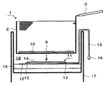
図1は本発明の電場形成装置付き揚げかごの第一実施形態図であり、(a)は斜視図、(b)は側面断面図である。図示するように、揚げかご1の内部底面部に電場形成用の電極板9を配設する。該電極板9の裏面四隅にはステンレス等の金属で形成された揚げかご1の本体2と絶縁するため、絶縁部材8を介して本体2に固定する。また、揚げかご1の底面部に前記電極板9と同等若しくは僅かに狭い開口部10を設けた構造とする。 FIG. 1 is a first embodiment of a lifting basket with an electric field forming device according to the present invention, in which (a) is a perspective view and (b) is a side sectional view. As shown in the drawing, an
図2は本発明の電場形成装置付き揚げかごの第二実施形態図であり、(a)は斜視図、(b)は側面断面図である。該第二実施形態は基本的に第一実施形態と同様であり、揚げ物が浮び上がらないように揚げかご1に蓋4を被せる構造としたものである。この場合、蓋4の上面手前側に摘み金具5を配設すると共に他端側には掛止金具7を配設し、揚げかご1の本体2の手前側内面上部に載置金具6を配設することにより、蓋4を揚げかご1の上部に載置することができる。該蓋4は着脱自在であるため、第一実施形態図において載置金具6を配設しておいても構わない。 FIG. 2 is a diagram showing a second embodiment of a lifting basket with an electric field forming device according to the present invention, wherein (a) is a perspective view and (b) is a side sectional view. The second embodiment is basically the same as the first embodiment, and has a structure in which a lid 4 is placed on the
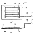
図3は本発明の電場形成装置付き揚げかごと対峙する油槽内電極の構造図であり、(a)は平面図、(b)は側面図である。図示するように、ステンレス等の金属板である底板12の上面に電場形成用の電極板14を配設する。該電極板14の裏面四隅には底板12と絶縁するため、絶縁部材13を介して底板12と固定する。また、該電極板14に高電圧発生装置から出力される高電圧を印加するための電極線15を接続する。更に、該電極線15の先端部には高電圧発生装置の2次側電源線と着脱自在にするための電極クリップ16を接続して構成する。 FIGS. 3A and 3B are structural views of the oil tank electrode facing the frying cage with the electric field forming device of the present invention, wherein FIG. 3A is a plan view and FIG. 3B is a side view. As shown in the drawing, an
また、図5は油槽内電極の第二実施例の構造図であり、(a)は平面図、(b)は側面図である。図示するように、ステンレス等の金属板である底板12の上面に電場形成用の電極板14を配設する。該電極板14の上面には複数の電極針20が形成され、高電圧発生装置から出力される高電圧を揚げかご1の内部底面部に配設した電極板9と接触させて通電することを可能とするものである。該電極板14の裏面四隅には底板12と絶縁するため、絶縁部材13を介して底板12と固定する。また、該電極板14に高電圧発生装置から出力される高電圧を印加するための電極線15を接続する。更に、該電極線15の先端部には高電圧発生装置の2次側電源線と着脱自在にするための電極クリップ16を接続して構成する。 FIGS. 5A and 5B are structural views of a second embodiment of the oil tank internal electrode, where FIG. 5A is a plan view and FIG. 5B is a side view. As shown in the drawing, an
また、図6は油槽内電極の第三実施例の構造図であり、(a)は平面図、(b)は側面図である。図示するように、ステンレス等の金属板である底板12の上面に電場形成用且つ高電圧装置から出力される高電圧を印加するための電極線15を波形状に敷設する。該波形の折数は図6では4回であるが、特に限定するものではない。なお、波形状のほかにループ状等に敷設しても構わない。該電極線15の裏面には底板12と固定するため、絶縁部材13を介して底板12と固定する。また、該波形状又はループ状等に敷設した電極線15の一先端部には高電圧発生装置の2次側電源線と着脱自在にするための電極クリップ16を接続して構成する。 FIGS. 6A and 6B are structural views of a third embodiment of the oil tank electrode, where FIG. 6A is a plan view and FIG. 6B is a side view. As shown in the figure, an
なお、上記説明における電極板9,14は高耐電圧特性及び耐熱性を有した絶縁材で全面若しくは上面を表面処理したものとし、電極線15も高耐電圧特性及び耐熱性を有したものとする。 Note that the
本発明の実施例を図を用いて説明する。図4は本発明の電場形成装置付き揚げかごと油槽内電極の嵌合図であり、図7は本発明の電場形成装置付き揚げかごを使用したフライヤーの一実施例の構成図である。 Embodiments of the present invention will be described with reference to the drawings. FIG. 4 is a fitting diagram of a frying basket with an electric field forming device and an oil tank electrode according to the present invention, and FIG. 7 is a block diagram of an embodiment of a fryer using the lifting basket with an electric field forming device according to the present invention.
図1及び図2に示すように、まず、揚げかご1の内部底面部に電場形成用の電極板9を配設する。該揚げかご1は、揚げかすが溜まらない程度の大きさの網目を有したステンレス製金網又はパンチングメタルが好適であり、電極板9は金属板又はパンチングメタルが好適である。また、揚げかご1の一側面に当該揚げかご1を持つための絶縁素材で形成された把手3を配設する。また、電極板9の裏面四隅にはステンレス等の金属で形成された揚げかご1の本体2と絶縁するため、絶縁部材8を介して本体2に固定する。また、揚げかご1の底面部に前記電極板9と同等若しくは僅かに狭い開口部10を設ける。 As shown in FIGS. 1 and 2, first, an
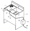
次に、上記揚げかご1の底面部にある開口部10と対峙する油槽内のヒートパイプ19の上部に油槽内電極11を配設する。該油槽内電極11はステンレス等の金属板である底板12の上面に上記電極板9に電場を誘導するための電極板14を配設し、又は電極線15を波形状又はループ状等に敷設し、絶縁部材13を介して底板12に固定したものである。また、該電極板14に接続した電極線15又は波形状又はループ状等に敷設した電極線15の先端部には高電圧発生装置21の2次側電源線23と着脱自在にするための電極クリップ16を接続する。 Next, the oil tank
また、図4に示すように、揚げかご1を油槽18内に入れる場合、揚げかご1の底面部に設けた開口部10よりヒートパイプ19の上部に設置した油槽内電極11の電極板14が揚げかご1の電極板9の裏面に接触するように嵌合させる。電極板14は図5で示した電極針20を複数形成したものや、図6で示した電極線15を波形状又はループ状等に敷設したもの等であっても構わない。 As shown in FIG. 4, when the
上記のように構成された揚げかご1を使用して揚げ物を揚げる場合、図7に示すように、フライヤー17の油槽18内に当該揚げかご1を把手3を持って入れる。この時、揚げかご1の底面部に設けた開口部10よりヒートパイプ19の上部に設置した油槽内電極11の電極板14が揚げかご1の電極板9の裏面に接触させておく。次に、電極線15に接続された電極クリップ16を高電圧発生装置21の2次側電源線23に接続された電極クリップ16’と接続する。その後、高電圧発生装置21の1次側電源線22に商用100/200V電源を供給することにより、2次側電源線23を経由して電極板14又は波形状又はループ状等に敷設した電極線15に電圧が数百〜数千ボルト,周波数が50Hz〜50KHz程度の高電圧が印加される。該高電圧は、揚げかご1の内部底面部に配設された電極板9に誘導若しくは通電される。このため、該電極板9により揚げかご1内に電場が形成され、少量の揚げ物であっても油の酸化を抑制して揚げ物を美味しく仕上げたり油煙や油臭を減少させる効果が得られることになる。また、電極線15は油槽18内に設置した油槽内電極11に接続され、揚げかご1とは分離されているため邪魔になることがない。 When frying the fried food using the
なお、図2に示すように、揚げかご1に蓋4を被せるようにすれば、揚げかご1内の揚げ物の浮き上がりを防止することができるため、該用途のために蓋4を使用しても構わない。 In addition, as shown in FIG. 2, if the lid 4 is covered with the
本発明の電場形成装置付き揚げかごは、食堂や仕出し弁当屋等においてフライや天ぷら等の揚げ物の量が少量の店舗で使用するものとして説明したが、少量多品種の揚げ物を揚げる店舗や、フライドポテト等のスナック油菓子を揚げる場合に使用しても構わない。また、揚げかご1を把手3で持つタイプについて説明したが、把手3が無いタイプの揚げかご1であっても構わない。 The frying basket with the electric field forming device of the present invention has been described as being used in a restaurant or a catered lunch box where the amount of fried food such as fried food and tempura is used in a small amount of stores. You may use it when fried snack oil confectionery, such as potato. Moreover, although the type which has the lifting
1 揚げかご
2 本体
3 把手
4 蓋
5 摘み金具
6 載置金具
7 掛止金具
8 絶縁部材
9 電極板
10 開口部
11 油槽内電極
12 底板
13 絶縁部材
14 電極板
15 電極線
16 電極クリップ
17 フライヤー
18 油槽
19 ヒートパイプ
20 電極針
21 高電圧印加装置
22 1次側電源線
23 2次側電源線DESCRIPTION OF
Claims (2)
Priority Applications (1)
| Application Number | Priority Date | Filing Date | Title |
|---|---|---|---|
| JP2005026986A JP2006187567A (en) | 2005-01-05 | 2005-01-05 | Frying basket with field forming device |
Applications Claiming Priority (1)
| Application Number | Priority Date | Filing Date | Title |
|---|---|---|---|
| JP2005026986A JP2006187567A (en) | 2005-01-05 | 2005-01-05 | Frying basket with field forming device |
Publications (2)
| Publication Number | Publication Date |
|---|---|
| JP2006187567A true JP2006187567A (en) | 2006-07-20 |
| JP2006187567A5 JP2006187567A5 (en) | 2007-07-12 |
Family
ID=36795277
Family Applications (1)
| Application Number | Title | Priority Date | Filing Date |
|---|---|---|---|
| JP2005026986A Pending JP2006187567A (en) | 2005-01-05 | 2005-01-05 | Frying basket with field forming device |
Country Status (1)
| Country | Link |
|---|---|
| JP (1) | JP2006187567A (en) |
Cited By (2)
| Publication number | Priority date | Publication date | Assignee | Title |
|---|---|---|---|---|
| JP2013005851A (en) * | 2011-06-23 | 2013-01-10 | Denshi Kogaku:Kk | Electric field processing apparatus for fryer |
| WO2018131140A1 (en) | 2017-01-13 | 2018-07-19 | 株式会社エバートロン | Fryer |
-
2005
- 2005-01-05 JP JP2005026986A patent/JP2006187567A/en active Pending
Cited By (5)
| Publication number | Priority date | Publication date | Assignee | Title |
|---|---|---|---|---|
| JP2013005851A (en) * | 2011-06-23 | 2013-01-10 | Denshi Kogaku:Kk | Electric field processing apparatus for fryer |
| WO2018131140A1 (en) | 2017-01-13 | 2018-07-19 | 株式会社エバートロン | Fryer |
| KR20180135073A (en) | 2017-01-13 | 2018-12-19 | 가부시키가이샤 에버트론 | Fryer |
| RU2756205C1 (en) * | 2017-01-13 | 2021-09-28 | Эвертрон Инк. | Frying apparatus |
| US11419455B2 (en) | 2017-01-13 | 2022-08-23 | Evertron Inc. | Fryer |
Similar Documents
| Publication | Publication Date | Title |
|---|---|---|
| JP5436463B2 (en) | Flyer | |
| JP5970297B2 (en) | Electric field treatment heating processing equipment | |
| JP5386346B2 (en) | Electric field treatment heating processing equipment | |
| JP2006187567A (en) | Frying basket with field forming device | |
| JP2005323982A (en) | Frying basket equipped with electric field forming device | |
| JP2006102447A (en) | Electric field forming apparatus for fryer | |
| JP6823297B2 (en) | Cooking utensils and cooking methods | |
| JP3147100U (en) | High voltage application device for fryer | |
| JP4367984B2 (en) | Electrostatic field processing equipment | |
| JP4722020B2 (en) | Electromagnetic induction heating cooker | |
| JP2014190611A (en) | Heating cooker | |
| JP3111795U (en) | Flyer plate | |
| JP2008110168A (en) | Cooking vessel for induction-heating | |
| JP5727104B1 (en) | Method for preventing oxidation of cooking oil | |
| WO2019167226A1 (en) | Cooking device and cooking method | |
| JP3136043U (en) | High voltage application device for fryer | |
| JP2010005357A (en) | High-voltage impression equipment for fryer | |
| JP5369459B2 (en) | Clad pan for induction heating cooker | |
| JP2002165705A (en) | Insulation electrode board applying high voltage for fryer | |
| JP3287549B2 (en) | Electromagnetic induction heating cooking container | |
| JP2019092635A (en) | Electric field treatment fryer | |
| TWI754014B (en) | Conditioning equipment and conditioning methods | |
| JP4088931B2 (en) | Grill grill and heating cooker equipped with the grill | |
| JP3146113U (en) | High voltage application device for fryer | |
| JP3142398U (en) | Antistatic structure of cooking oil tank equipped with cooking oil redox device |
Legal Events
| Date | Code | Title | Description |
|---|---|---|---|
| A521 | Written amendment |
Effective date: 20070415 Free format text: JAPANESE INTERMEDIATE CODE: A523 |