JP2006183263A - Device and adapter for connecting attachment piping of hydraulic excavator - Google Patents
Device and adapter for connecting attachment piping of hydraulic excavator Download PDFInfo
- Publication number
- JP2006183263A JP2006183263A JP2004375642A JP2004375642A JP2006183263A JP 2006183263 A JP2006183263 A JP 2006183263A JP 2004375642 A JP2004375642 A JP 2004375642A JP 2004375642 A JP2004375642 A JP 2004375642A JP 2006183263 A JP2006183263 A JP 2006183263A
- Authority
- JP
- Japan
- Prior art keywords
- connection
- attachment
- pipe
- hydraulic excavator
- piping
- Prior art date
- Legal status (The legal status is an assumption and is not a legal conclusion. Google has not performed a legal analysis and makes no representation as to the accuracy of the status listed.)
- Pending
Links
Images

Classifications
-
- E—FIXED CONSTRUCTIONS
- E02—HYDRAULIC ENGINEERING; FOUNDATIONS; SOIL SHIFTING
- E02F—DREDGING; SOIL-SHIFTING
- E02F9/00—Component parts of dredgers or soil-shifting machines, not restricted to one of the kinds covered by groups E02F3/00 - E02F7/00
- E02F9/20—Drives; Control devices
- E02F9/22—Hydraulic or pneumatic drives
- E02F9/2264—Arrangements or adaptations of elements for hydraulic drives
- E02F9/2267—Valves or distributors
-
- E—FIXED CONSTRUCTIONS
- E02—HYDRAULIC ENGINEERING; FOUNDATIONS; SOIL SHIFTING
- E02F—DREDGING; SOIL-SHIFTING
- E02F9/00—Component parts of dredgers or soil-shifting machines, not restricted to one of the kinds covered by groups E02F3/00 - E02F7/00
- E02F9/20—Drives; Control devices
- E02F9/22—Hydraulic or pneumatic drives
- E02F9/2264—Arrangements or adaptations of elements for hydraulic drives
- E02F9/2275—Hoses and supports therefor and protection therefor
Abstract
Description
本発明は、油圧ショベルの作業アーム先端に付設されるアタッチメントのための配管接続装置及び接続用アダプタに関する。 The present invention relates to a pipe connection device and a connection adapter for an attachment attached to the tip of a work arm of a hydraulic excavator.
油圧ショベルの多関節アームの先端には、通常、掘削用のバケットが取り付けられているが、作業の汎用性を向上させるために、掘削用のバケットに変えて、破砕機等のアタッチメントを多関節アームの先端に取り付けて使用することがある。 An excavator bucket is usually attached to the tip of the articulated arm of a hydraulic excavator. However, in order to improve the versatility of the work, the excavator bucket is replaced with an articulated attachment such as a crusher. Sometimes attached to the tip of an arm.
このように交換されたアタッチメントに作動油を供給するために、油圧ショベルの本体の油圧源に接続した配管を、多関節アームの先端側の側部に配設し、その配管の先端にアタッチメントの配管が接続される接続口部を設けている(例えば、特許文献1参照。)。 In order to supply hydraulic oil to the attachment thus replaced, a pipe connected to the hydraulic power source of the main body of the excavator is arranged on the side of the tip side of the articulated arm, and the attachment is attached to the tip of the pipe. The connection port part to which piping is connected is provided (for example, refer patent document 1).
一方、油圧ショベルの機能性を有効的に利用するために、近年では、その多関節アームの先端に、種々のアタッチメントを装備し使用する要求がある。この場合、各アタッチ側の給排用の配管における接続口のねじのサイズ、種類の形式が、上述したアタッチメント接続配管の接続口部におけるねじのサイズ、種類の形式とは異なることがあるので、このねじのサイズ、種類の形式に適合する補助用の接続アダプタを数種類用意し、使用するアタッチメントに対応する補助用の接続アダプタを、その都度、アタッチメント接続配管の接続口部に付け替え、この補助用の接続アダプタにアタッチメント側の給排用の配管を接続していた。 On the other hand, in order to effectively use the functionality of a hydraulic excavator, in recent years, there is a demand to use various attachments at the tip of the articulated arm. In this case, the size and type of the connection port screw in the supply / discharge piping on each attachment side may differ from the screw size and type in the connection port portion of the attachment connection pipe described above. Several types of auxiliary connection adapters suitable for the size and type of this screw are prepared, and the auxiliary connection adapter corresponding to the attachment to be used is replaced with the connection port of the attachment connection pipe each time. The connection supply / exhaust piping was connected to the connection adapter.
このような接続構成では、補助用の接続アダプタの付け替えが必要になり、その接続作業が面倒であるとともに、複数の補助用の接続アダプタを常備しなければならないという問題がある。 In such a connection configuration, it is necessary to replace the auxiliary connection adapter, and there is a problem that the connection work is troublesome and a plurality of auxiliary connection adapters must be provided.
本発明は、上述の問題点を改善し、アタッチメント側の配管を、アタッチメント接続配管に容易に接続することができる油圧ショベルのアタッチメント配管接続装置及び接続用アダプタを提供することを目的とする。 An object of the present invention is to provide an attachment pipe connection device and a connection adapter for a hydraulic excavator that can improve the above-described problems and can easily connect the pipe on the attachment side to the attachment connection pipe.
本発明は、上記の目的を達成するために、第1の発明は、油圧ショベルの多関節アームの先端側に、アタッチメント接続配管を備えた油圧ショベルのアタッチメント配管接続装置において、前記アタッチメント接続配管の先端側に接続したストップ弁と、前記ストップ弁に連結し、回り継ぎ手によって回転可能でそれぞれ異なるねじのサイズ、種類の形式の接続ねじを持つ複数の配管接続口を有する接続部材とを備えたことを特徴とする油圧ショベルのアタッチメント配管接続装置にある。 In order to achieve the above object, the present invention provides a hydraulic excavator attachment pipe connection device including an attachment connection pipe on the distal end side of the articulated arm of the hydraulic excavator. A stop valve connected to the distal end side and a connecting member connected to the stop valve and rotatable by a swivel joint and having a plurality of pipe connection ports each having different screw sizes and types of connection screws It is in the attachment piping connection apparatus of the hydraulic excavator characterized by this.
また、第2の発明は、油圧ショベルの多関節アームの先端側に、アタッチメント接続配管を備えた油圧ショベルのアタッチメント配管接続装置において、前記アタッチメント接続配管の先端側に接続する一方の開口と他方の開口とこれらの開口を連通遮断する弁体とを有するストップ弁と、前記ストップ弁の他方の開口に一端を連結し、他端を前記多関節アームの側方から外方に屈曲した曲管と、前記曲管に回り継ぎ手を介して回転可能に連結され、それぞれ異なるねじのサイズ、種類の形式の接続ねじを持つ複数の配管接続口を有する接続部材とを備えたことを特徴とする油圧ショベルのアタッチメント配管接続装置にある。 In addition, the second invention is an attachment pipe connection device for a hydraulic excavator provided with an attachment connection pipe on the tip side of the articulated arm of the hydraulic excavator, wherein one opening connected to the tip side of the attachment connection pipe and the other A stop valve having an opening and a valve body that cuts off and communicates with the opening; a bent pipe having one end connected to the other opening of the stop valve and the other end bent outward from the side of the articulated arm; And a connecting member having a plurality of pipe connection ports each having a connection thread of different screw sizes and types, each of which is rotatably connected to the curved pipe via a swivel joint. The attachment pipe connection device.
更に、第3の発明は、油圧ショベルの多関節アームの先端側に、アタッチメント接続配管を備えた油圧ショベルのアタッチメント配管接続装置において、前記アタッチメント接続配管の先端側に接続する一方の開口と他方の開口とこれらの開口を連通遮断する弁体とを有するストップ弁と、前記ストップ弁の他方の開口に一端を連結し、他端側にそれぞれ異なるねじのサイズ、種類の形式の接続ねじを持つ複数の配管接続口を有する接続部材とを備えたことを特徴とする油圧ショベルのアタッチメント配管接続装置にある。 Furthermore, a third aspect of the present invention is the attachment piping connection device for a hydraulic excavator provided with an attachment connection pipe on the distal end side of the articulated arm of the hydraulic excavator, wherein one opening connected to the distal end side of the attachment connection pipe and the other A plurality of stop valves each having an opening and a valve body that cuts off and communicates with the openings; and one end connected to the other opening of the stop valve, each having a connection screw of a different screw size and type on the other end side. An attachment pipe connection device for a hydraulic excavator, characterized in that the connection member has a pipe connection port.
また、第4の発明は、油圧ショベルの多関節アームの先端側に、アタッチメント接続配管を備えた油圧ショベルのアタッチメント配管接続用アダプタにおいて、前記アタッチメント接続配管の先端側に一端が接続され、他端が閉塞している曲管と、前記曲管に回り継ぎ手を介して回転可能に連結され、それぞれ異なるねじのサイズ、種類の形式の接続ねじを持つ複数の配管接続口を有する接続部材とを備えたことを特徴とする油圧ショベルのアタッチメント配管接続用アダプタにある。 According to a fourth aspect of the present invention, there is provided an attachment pipe connection adapter for a hydraulic excavator provided with an attachment connection pipe at the tip end side of the articulated arm of the hydraulic excavator, wherein one end is connected to the tip end side of the attachment connection pipe. And a connecting member having a plurality of pipe connection ports each connected to the curved pipe through a joint and having a connection thread of different screw sizes and types. This is an attachment pipe connection adapter for a hydraulic excavator.
本発明によれば、アタッチメント接続配管の接続口部に、種々のアタッチメントの配管を接続することができる接続部を設けたので、アタッチメント交換時の配管接続作業が容易になり、その作業性が向上するとともに、配管接続のための作業時間も短縮することができるので、油圧ショベルの作業復帰性を高めることができる。 According to the present invention, since the connection part that can connect various attachment pipes is provided at the connection port part of the attachment connection pipe, the pipe connection work at the time of replacing the attachment becomes easy and the workability is improved. In addition, since the work time for connecting the pipes can be shortened, the work returnability of the hydraulic excavator can be improved.
以下、本発明の油圧ショベルのアタッチメント配管接続装置の実施の形態を図面を用いて説明する。
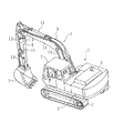
図1は本発明の油圧ショベルのアタッチメント配管接続装置の一実施の形態を備えた油圧ショベル形式の作業機械を示す斜視図で、この図1において、作業機械1は、走行体2と、この走行体2上に旋回可能に設けた旋回体3と、旋回体3上に搭載した動力源4と、旋回体3の前方側部に設けた運転室5と、旋回体3の前部に俯仰動可能に設けた多関節アーム6と、多関節アーム6の先端に回動可能に設けた掘削用バケット7とで構成されている。
DESCRIPTION OF EMBODIMENTS Hereinafter, embodiments of an attachment piping connection device for a hydraulic excavator according to the present invention will be described with reference to the drawings.
FIG. 1 is a perspective view showing a hydraulic excavator type working machine equipped with an embodiment of an attachment piping connection device for a hydraulic excavator of the present invention. In FIG. 1, the working machine 1 includes a
多関節アーム6は、基部を旋回体3の前部に俯仰動可能に設けたブーム8と、このブーム8の先端に回動可能に設けたアーム9とで構成されている。このアーム9の先端には、アタッチメントの1つである掘削用バケット7が着脱可能に取り付けられている。ブーム8は、これと旋回体3との間に設けたシリンダ10によって俯仰動される。アーム9はこれとブーム8との間に設けたシリンダ11によって回動する。掘削用バケット7はリンク12を介して連結したシリンダ13によって回動される。
The articulated arm 6 includes a boom 8 whose base is provided on the front part of the revolving
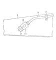
ブーム7およびアーム9の側部には、動力源4に接続するアタッチメント接続配管14がそれぞれ保持具15によって保持されて配設されている。このアタッチメント接続配管14の先端は、アーム9の先端側の側部にそれぞれ位置している。アタッチメント接続配管14の先端には、図2に示すようにストップ弁16とこのストップ弁16に接続し複数の配管接続口を有する接続部材17とからなる配管接続装置18がそれぞれ設けられている。
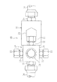
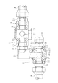
この配管接続装置18の詳細な構成を図3及び図4を用いて説明する。図3は図2に示す本発明のアタッチメント配管接続装置の一実施の形態をさらに拡大して示す正面図、図4は図3に示す本発明のアタッチメント配管接続装置の一実施の形態を一部断面にて示す平面図である。これらの図において、図1及び図2と同符号のものは同一部分である。ストップ弁16は、一方側の連通孔19と他方側の連通孔20とを有する弁筐21と、この弁筐21に回転可能に設けられ、連通孔19,20とを連通遮断する弁孔22を有する弁体23とを備えている。
A detailed configuration of the
ストップ弁16は、その一方側の連通孔19とアタッチメント接続配管14の先端側とにそれぞれねじ込まれた接続ねじ24によって、鋼管製のアタッチメント接続配管14の先端に保持されているとともに、連通状態に接続されている。
The
ストップ弁16の他方側の連通孔20には、接続ねじ25によって曲管26の一端が連結されている。この曲管26の他端側は閉塞されており、曲管26内の通路に連結する1つの連通孔27を有している。曲管26の他端側の外周面は、後述する接続部材とにより回り継ぎ手(スイベルジョイント)を構成する。
One end of a
曲管26の他端側の外周面には、曲管26の連通孔27に選択的に連通する複数個(この例では4個)の連通孔28を有する接続部材29が回転可能に設けられている。この接続部材29は、スナップリング30によって曲管26の他端側部の軸線方向への移動を抑えられていると共に、シール31によって摺動面からの油漏れを防止するように構成されている。
A connecting
接続部材29の各連通孔28には、附設するアタッチメント側の配管における接続ねじに適合させるために、ねじのサイズ、種類の形式が異なる接続ねじ32の一方のねじ部がそれぞれねじ込まれている。これらの接続ねじ32のうち、アタッチメン側の配管34が接続されていない接続ねじ32の他方のねじ部には、閉塞キャップ33がねじ込まれている。図3及び図4においては、図面上左側端の接続ねじ32のねじ部に、アタッチメント側の配管34を接続した状態を示しており、他のアタッチメントを使用する場合、接続部材29を曲管26回りに回転して、他のアタッチメント側の配管34における接続ねじに適合する接続ねじ32を図面上左側に位置させ、この左側に位置させた接続ねじ32の他方のねじ部に他のアタッチメント側の配管34における接続ねじをねじ込み連結する。
In each
次に、上述した本発明の油圧ショベルのアタッチメント配管接続装置及び接続用アダプタの一実施の形態の動作を図面を用いて説明する。
図1に示すように多関節アーム6の先端に設けた掘削用バケット7によって土砂等を掘削する状態から、例えば破砕機等のアタッチメントによってコンクリート等の破砕作業を行う場合には、まず多関節アーム6の先端から掘削用バケット7を取り外し、多関節アーム6の先端に例えば破砕機等のアタッチメントを装着する。
Next, the operation of an embodiment of the above-described attachment pipe connection device and connection adapter for a hydraulic excavator according to the present invention will be described with reference to the drawings.
As shown in FIG. 1, when crushing concrete or the like with an attachment such as a crusher from the state where excavation bucket 7 provided at the tip of the articulated arm 6 is excavated, first, the articulated arm is used. The excavation bucket 7 is removed from the tip of 6 and an attachment such as a crusher is attached to the tip of the articulated arm 6.
次に、図3及び図4に示す各接続部材29を曲管26回りに回転して、アタッチメント側の配管34の接続口における接続ねじと同じサイズ、種類の形式の接続ねじ32が、配管の接続上の観点から図3及び図4に示す左側に位置させ、閉塞キャップ33を接続ねじ32から取り外す。その後、アタッチメント側の配管34の接続ねじを、左側に位置させた接続部材29における接続ねじ32の他方のねじ部にねじ込み結合する。
Next, each
次に、ストップ弁16の弁体23を回転し、その弁孔22を弁筐21の一方側の連通孔19と他方側の連通孔20とに一致させれば、アタッチメント接続配管14を、それぞれストップ弁16、曲管26接続部材の各連通孔を通してアタッチメント側の配管34に連通させることができる。これにより、油圧源からの圧油をアタッチメントに供給し、アタッチメントからの排油を油圧源側に戻すことができる。
Next, if the
上述したように、各接続部材29には、装着すべきアタッチメントの配管34の接続口における接合ねじと適合する同ねじ形式の接続ねじ32を複数個設けたので、アタッチメント側の配管34の接続が容易になり、その作業性が向上するとともに、配管接続のための作業時間も短縮することができるので、油圧ショベルの作業復帰性を高めることができる。また、従来用いていた補助用の接続アダプタを別途用意しておく必要もなくなる。
As described above, each
なお、上述の実施の形態においては、接続部材29に4個の接続ねじ32を設けたが、この接続ねじ32の取付け個数は適宜変えることは可能である。
In the above-described embodiment, four
図5は本発明の油圧ショベルのアタッチメント配管接続装置及び接続用アダプタの他の実施の形態を示すもので、この図において図1乃至図4に示す符号と同符号のものは同一または相当する部分である。この実施の形態は、管体35に複数の分岐部を設け、この分岐部にそれぞれ接続ねじ32を設け、この管体35をストップ弁16に連結して構成したものである。
FIG. 5 shows another embodiment of the attachment pipe connection device and connection adapter for a hydraulic excavator according to the present invention. In this figure, the same reference numerals as those shown in FIGS. 1 to 4 denote the same or corresponding parts. It is. In this embodiment, the
この実施の形態によれば、アタッチメント側の配管34の接続が容易になり、その作業性が向上するとともに、配管接続のための作業時間も短縮することができるので、油圧ショベルの作業復帰性を高めることができる。また、従来用いていた補助用の接続アダプタを用意しておく必要もなく、製作コストが安価である。
According to this embodiment, the connection of the
1 作業機械
6 多関節アーム
9 アーム
14 アタッチメント接続配管
16 ストップ弁
17 接続部材
DESCRIPTION OF SYMBOLS 1 Work machine 6 Articulated
Claims (4)
Priority Applications (1)
| Application Number | Priority Date | Filing Date | Title |
|---|---|---|---|
| JP2004375642A JP2006183263A (en) | 2004-12-27 | 2004-12-27 | Device and adapter for connecting attachment piping of hydraulic excavator |
Applications Claiming Priority (1)
| Application Number | Priority Date | Filing Date | Title |
|---|---|---|---|
| JP2004375642A JP2006183263A (en) | 2004-12-27 | 2004-12-27 | Device and adapter for connecting attachment piping of hydraulic excavator |
Publications (1)
| Publication Number | Publication Date |
|---|---|
| JP2006183263A true JP2006183263A (en) | 2006-07-13 |
Family
ID=36736575
Family Applications (1)
| Application Number | Title | Priority Date | Filing Date |
|---|---|---|---|
| JP2004375642A Pending JP2006183263A (en) | 2004-12-27 | 2004-12-27 | Device and adapter for connecting attachment piping of hydraulic excavator |
Country Status (1)
| Country | Link |
|---|---|
| JP (1) | JP2006183263A (en) |
Cited By (2)
| Publication number | Priority date | Publication date | Assignee | Title |
|---|---|---|---|---|
| JP2014152466A (en) * | 2013-02-06 | 2014-08-25 | Kobelco Contstruction Machinery Ltd | Valve fixing structure for construction machine |
| KR20230027496A (en) * | 2021-08-19 | 2023-02-28 | 주식회사 경원테크 | Structure for inputting oil pressure to bucket |
-
2004
- 2004-12-27 JP JP2004375642A patent/JP2006183263A/en active Pending
Cited By (3)
| Publication number | Priority date | Publication date | Assignee | Title |
|---|---|---|---|---|
| JP2014152466A (en) * | 2013-02-06 | 2014-08-25 | Kobelco Contstruction Machinery Ltd | Valve fixing structure for construction machine |
| KR20230027496A (en) * | 2021-08-19 | 2023-02-28 | 주식회사 경원테크 | Structure for inputting oil pressure to bucket |
| KR102566594B1 (en) | 2021-08-19 | 2023-08-16 | 주식회사 경원테크 | Structure for inputting oil pressure to bucket |
Similar Documents
| Publication | Publication Date | Title |
|---|---|---|
| JPWO2005061805A1 (en) | Construction machine swivel joint | |
| JP2006274725A (en) | Working machine | |
| US9382926B2 (en) | Oil passage change-over valve | |
| JP2006183263A (en) | Device and adapter for connecting attachment piping of hydraulic excavator | |
| JP2004182391A (en) | Multifunctional working device for constructing forest road | |
| EP1918593A2 (en) | Depressurization apparatus for hydraulic pipe and hydraulic pipe structure | |
| KR102195915B1 (en) | Hydraulic hose connector for hydraulic breaker | |
| JP2001289237A (en) | Two member connecting device | |
| JP2005133507A (en) | Work machine attaching/detaching device by means of pin | |
| JP2011184920A (en) | Working arm for construction machinery | |
| JP3698557B2 (en) | Construction machine working equipment | |
| JP2009007760A (en) | Construction machine | |
| KR100407433B1 (en) | Hydraulic turning joint and attachment for construction equipment using the same | |
| JP6663379B2 (en) | Construction machinery | |
| JP2006292072A (en) | Quick coupler device | |
| JP4136360B2 (en) | Work tool attachment / detachment device | |
| KR200396469Y1 (en) | The go straight ahead type of crane having swivels | |
| JP2000170201A (en) | Working device for construction machine | |
| KR200245906Y1 (en) | Excavator | |
| JPH07317329A (en) | Piping structure of hydraulic working vehicle | |
| JP3936592B2 (en) | Pipe fitting | |
| JP3936593B2 (en) | Hydraulic device | |
| JP2004092706A (en) | Working machine with boom and its using method | |
| KR200273573Y1 (en) | A honeybee rotation device exacvate head | |
| JPH0614255U (en) | Hydraulic circuit of power shovel |