JP2006171237A - Image forming apparatus - Google Patents
Image forming apparatus Download PDFInfo
- Publication number
- JP2006171237A JP2006171237A JP2004361950A JP2004361950A JP2006171237A JP 2006171237 A JP2006171237 A JP 2006171237A JP 2004361950 A JP2004361950 A JP 2004361950A JP 2004361950 A JP2004361950 A JP 2004361950A JP 2006171237 A JP2006171237 A JP 2006171237A
- Authority
- JP
- Japan
- Prior art keywords
- temperature
- cooling
- fixing
- unit
- cooling fan
- Prior art date
- Legal status (The legal status is an assumption and is not a legal conclusion. Google has not performed a legal analysis and makes no representation as to the accuracy of the status listed.)
- Granted
Links
Images


Classifications
-
- G—PHYSICS
- G03—PHOTOGRAPHY; CINEMATOGRAPHY; ANALOGOUS TECHNIQUES USING WAVES OTHER THAN OPTICAL WAVES; ELECTROGRAPHY; HOLOGRAPHY
- G03G—ELECTROGRAPHY; ELECTROPHOTOGRAPHY; MAGNETOGRAPHY
- G03G15/00—Apparatus for electrographic processes using a charge pattern
- G03G15/20—Apparatus for electrographic processes using a charge pattern for fixing, e.g. by using heat
- G03G15/2003—Apparatus for electrographic processes using a charge pattern for fixing, e.g. by using heat using heat
- G03G15/2014—Apparatus for electrographic processes using a charge pattern for fixing, e.g. by using heat using heat using contact heat
- G03G15/2017—Structural details of the fixing unit in general, e.g. cooling means, heat shielding means
-
- G—PHYSICS
- G03—PHOTOGRAPHY; CINEMATOGRAPHY; ANALOGOUS TECHNIQUES USING WAVES OTHER THAN OPTICAL WAVES; ELECTROGRAPHY; HOLOGRAPHY
- G03G—ELECTROGRAPHY; ELECTROPHOTOGRAPHY; MAGNETOGRAPHY
- G03G2215/00—Apparatus for electrophotographic processes
- G03G2215/20—Details of the fixing device or porcess
Landscapes
- Physics & Mathematics (AREA)
- General Physics & Mathematics (AREA)
- Fixing For Electrophotography (AREA)
- Control Or Security For Electrophotography (AREA)
Abstract
Description
本発明は、画像形成装置、例えば電子写真プリンタや複写機、ファクシミリなどの定着器に関するものである。 The present invention relates to an image forming apparatus, for example, a fixing device such as an electrophotographic printer, a copying machine, or a facsimile.
従来、電子写真方式のプリンタやファクシミリ等に用いられる定着器では、記録媒体上に転写された現像剤像を加熱、溶融し、所定の圧力で加圧することにより記録媒体上に現像剤像を定着している。定着器はこの定着に必要な熱量を供給するために熱源を備えており、この熱源は定着器の温度を定着可能な所定の温度範囲(以下「印刷可能温度範囲」という)で推移するように制御されている。(例えば、特許文献1参照。)。 Conventionally, in a fixing device used for an electrophotographic printer, a facsimile, etc., a developer image transferred onto a recording medium is heated and melted, and the developer image is fixed on the recording medium by pressurizing at a predetermined pressure. is doing. The fixing device is provided with a heat source for supplying the amount of heat necessary for the fixing, and the heat source changes the temperature of the fixing device within a predetermined temperature range in which the fixing device can be fixed (hereinafter referred to as “printable temperature range”). It is controlled. (For example, refer to Patent Document 1).
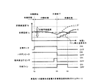
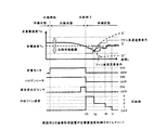
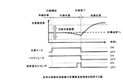
図13は、従来の制御による定着器の印刷開始時から印刷終了までの定着制御における各制御信号と定着器の温度Tdの変化を示すグラフである。同図のハロゲンヒータ信号は定着器を構成する定着ローラ内部に設けたハロゲンヒータをオンオフする信号である。定着モータ信号は定着モータをオンオフし定着を開始または定着を停止する信号である。また、媒体排出口センサ信号は、印刷が終了し記録媒体が排出口に排出されたことを検出する検出信号である。 FIG. 13 is a graph showing changes in each control signal and the temperature Td of the fixing device in fixing control from the start of printing of the fixing device to the end of printing by the conventional control. The halogen heater signal in the figure is a signal for turning on / off the halogen heater provided in the fixing roller constituting the fixing device. The fixing motor signal is a signal for starting / stopping fixing by turning on / off the fixing motor. The medium discharge port sensor signal is a detection signal for detecting that printing is completed and the recording medium is discharged to the discharge port.
定着過程における前述の印刷可能温度範囲とは、記録媒体に良好にトナーが定着可能な温度範囲をいい、この温度範囲よりも低い温度で印刷を開始するとコールドオフセットが発生し、トナーが十分に融解しないために記録媒体への付着力が不足し、トナーが記録媒体ではなく定着ローラヘ付着する現象が発生する。一方、前記温度範囲よりも高い温度で印刷を行うとホットオフセットが発生し、トナーの粘性が低すぎて、トナーが記録媒体ではなく定着ローラヘ付着する現象が発生する。 The above-mentioned printable temperature range in the fixing process refers to a temperature range in which toner can be satisfactorily fixed on a recording medium. When printing is started at a temperature lower than this temperature range, a cold offset occurs and the toner is sufficiently melted. Therefore, the adhesion force to the recording medium is insufficient, and a phenomenon occurs in which the toner adheres not to the recording medium but to the fixing roller. On the other hand, when printing is performed at a temperature higher than the above temperature range, hot offset occurs, and the viscosity of the toner is too low, causing a phenomenon that the toner adheres to the fixing roller instead of the recording medium.
この印刷可能温度範囲は、記録媒体の種類や厚さ等によって決定されるものであり、通常、記録媒体の種類や厚さなどに対応する設定温度をテーブルとして保持している。 This printable temperature range is determined by the type and thickness of the recording medium, and normally, a set temperature corresponding to the type and thickness of the recording medium is held as a table.
そして、印刷開始時は、まず定着器に設けた温度センサによって定着器が印刷可能温度範囲にあるか否かを検出し、図13のように、図中左側の待機状態での温度が、印刷する記録媒体の印刷可能温度範囲よりも低い場合、目標温度を印刷する記録媒体に対応する温度に設定した後、定着器のハロゲンヒータに通電して加熱し、印刷可能温度範囲に達するまで待機した後、印刷動作を開始する。 At the start of printing, first, a temperature sensor provided in the fixing device detects whether or not the fixing device is in a printable temperature range. As shown in FIG. If the temperature is lower than the printable temperature range of the recording medium to be printed, set the target temperature to a temperature corresponding to the printing medium to be printed, then heat by energizing the halogen heater of the fuser and wait until it reaches the printable temperature range Thereafter, the printing operation is started.
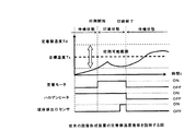
一方、図14のように、図中左側の待機状態での温度が、すでに印刷する記録媒体の印刷可能温度範囲である場合は、定着器の温度が上昇することを待つことなく、目標温度を印刷する記録媒体に対応する温度に設定した後、定着器のハロゲンヒータに通電を開始し印刷動作を開始する。 On the other hand, as shown in FIG. 14, when the temperature in the standby state on the left side in the drawing is already in the printable temperature range of the recording medium to be printed, the target temperature is set without waiting for the temperature of the fixing device to rise. After setting the temperature corresponding to the recording medium to be printed, the energization of the halogen heater of the fixing device is started to start the printing operation.
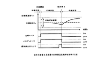
また、図15のように、図中左側の待機状態での温度が、印刷する記録媒体の印刷可能温度範囲よりも高い場合は、目標温度を印刷する記録媒体に対応する温度に設定した後、ハロゲンヒータに通電せず、印刷可能温度範囲になるまで定着器を放熱させ、印刷可能温度範囲に達した後、印刷動作を開始する。 Further, as shown in FIG. 15, when the temperature in the standby state on the left side in the drawing is higher than the printable temperature range of the recording medium to be printed, after setting the target temperature to the temperature corresponding to the recording medium to be printed, The halogen heater is not energized, and the fixing device is dissipated until reaching the printable temperature range. After reaching the printable temperature range, the printing operation is started.
以上のように制御することにより、図13ないし図15に示したように定着器の温度制御が行われ、印刷動作が行われている。
しかしながら、一般に、印刷開始時点では何枚印刷されるか予測できないので印刷枚数が多い場合を考慮し、記録媒体の通過により温度が低下し印刷可能温度範囲以下となることを防止するために、定着器には出来るだけ多くの熱量を投入するようにしている。 However, in general, since it is not possible to predict how many sheets will be printed at the start of printing, in order to prevent the temperature from dropping due to the passage of the recording medium and falling below the printable temperature range, fixing is considered. As much heat as possible is put into the vessel.
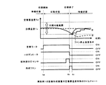
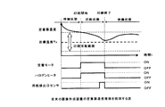
上記のように定着器に多くの熱量を投入した場合、印刷枚数が少ない場合では、記録媒体の通過により奪われる熱量が少ないので、記録媒体定着時に奪われず、残った熱量によって定着器の温度が上昇する現象(以下、「オーバーシュート」という)が発生し印刷可能温度範囲を越えてしまうことがある。図16は、このオーバーシュートを示した図である。 When a large amount of heat is input to the fixing unit as described above, when the number of printed sheets is small, the amount of heat taken away by the passage of the recording medium is small. An increasing phenomenon (hereinafter referred to as “overshoot”) may occur and exceed the printable temperature range. FIG. 16 is a diagram showing this overshoot.
同図に示したように、定着器の熱源であるハロゲンヒータおよび定着モータをオンして定着を行った後、記録媒体の排出が検出され、ハロゲンヒータおよび定着モータオフし印刷を終了すると、前記残った熱量により定着器の温度が急激に上昇し、印刷可能温度範囲の上限を越えてしまう前記オーバーシュートが発生している。 As shown in the figure, after fixing by turning on the halogen heater and the fixing motor, which are heat sources of the fixing device, the discharge of the recording medium is detected. Due to the amount of heat, the temperature of the fixing device suddenly rises, and the overshoot that exceeds the upper limit of the printable temperature range occurs.
このような状態となると、次の印刷を開始するまでに定着器の温度を印刷可能温度範囲まで下げる必要があるので、図15で説明したような待ち時間が発生してしまう。 In such a state, it is necessary to lower the temperature of the fixing device to the printable temperature range before starting the next printing, so that the waiting time described with reference to FIG. 15 occurs.
逆に、多量の印刷を行った場合では、定着器の熱量が奪われ、定着器の温度が下がり印刷可能温度範囲の下限を越えてしまう現象(以下、「アンダーシュート」という)が発生し、図13で説明したような待ち時間が発生してしまうことがあった。 On the contrary, when a large amount of printing is performed, the amount of heat of the fixing device is deprived, the temperature of the fixing device drops and exceeds the lower limit of the printable temperature range (hereinafter referred to as “undershoot”), There is a case where a waiting time as described in FIG. 13 occurs.
本発明は、前述の課題を解決するため次の構成を採用する。すなわち、現像剤像を記録媒体上に定着させる定着手段と、前記定着手段を加熱する加熱手段と、
前記加熱手段により加熱された前記定着手段の温度を検出する温度検出手段と、前記定着手段を冷却する冷却手段と、前記加熱手段の駆動を制御する加熱制御手段と、前記冷却手段の駆動を制御する冷却制御手段とを備え、前記定着手段による定着が終了されると、前記温度検出手段により検出される温度が第1の温度以下であれば前記冷却制御手段は前記冷却手段の駆動を制限するようにした。
The present invention employs the following configuration in order to solve the above-described problems. That is, a fixing unit that fixes the developer image on the recording medium, a heating unit that heats the fixing unit,
Temperature detecting means for detecting the temperature of the fixing means heated by the heating means; cooling means for cooling the fixing means; heating control means for controlling the driving of the heating means; and controlling the driving of the cooling means. And when the fixing by the fixing unit is completed, the cooling control unit limits the driving of the cooling unit if the temperature detected by the temperature detecting unit is equal to or lower than a first temperature. I did it.
本発明の画像形成装置によれば、印刷終了後、冷却ファンを回転させて定着器の温度を下げる画像形成装置において、印刷可能温度範囲の略下限温度を起点とし、所定の時間ごとに所定の温度だけ増加させ、徐々に目標温度に近づくように冷却ファン停止温度条件を設定し、当該設定した温度以下に定着器の温度が低下したときに冷却ファンを停止するようにしたので、定着器の温度を確実に印刷可能温度範囲とすることができ、次の印刷開始までの待機時間をなくすことができる。 According to the image forming apparatus of the present invention, in the image forming apparatus in which the cooling fan is rotated to lower the temperature of the fixing device after the printing is finished, the predetermined lower limit temperature of the printable temperature range is set as a starting point, and the predetermined temperature is set every predetermined time. The cooling fan stop temperature condition was set so that the temperature was increased and gradually approached the target temperature, and the cooling fan was stopped when the temperature of the fuser dropped below the set temperature. The temperature can be reliably set within the printable temperature range, and the waiting time until the next printing start can be eliminated.
以下、本発明に係る実施の形態例を、図面を用いて説明する。なお、図面に共通する要素には同一の符号を付す。 Embodiments of the present invention will be described below with reference to the drawings. In addition, the same code | symbol is attached | subjected to the element common to drawing.
実施例1の画像形成装置は、印刷終了からの経過時間に応じた冷却ファンの停止温度条件を設け、印刷終了後、定着器の温度が当該設定した温度条件以下となったとき、冷却ファンを停止するようにしたものである。 The image forming apparatus according to the first exemplary embodiment has a cooling fan stop temperature condition corresponding to an elapsed time from the end of printing. When the temperature of the fixing device becomes equal to or lower than the set temperature condition after the printing ends, the cooling fan is turned on. It is intended to stop.
(画像形成装置の構成)
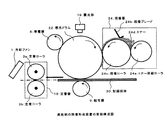
図1および図2は実施例1の画像形成装置の印刷機構等の要部構成図および制御系ブロック図である。同図に示したように、画像形成装置は、印刷等の動作を制御する印刷制御部20と、印刷制御部20の制御に応じて記録光を発光させる露光部19と、露光部19からの記録光に応じた静電潜像を形成するための有機薄膜等の感光体を有する感光ドラム22と、感光ドラム22上の静電潜像を現像する現像器24と、記録媒体30を搬送する図示しない搬送部と、感光ドラム22上に現像されたトナー像を記録媒体30に転写する転写器9と、転写された像を定着させる定着器18からなる。
(Configuration of image forming apparatus)
FIG. 1 and FIG. 2 are a configuration diagram and a control system block diagram of a main part of a printing mechanism and the like of the image forming apparatus according to the first embodiment. As shown in the figure, the image forming apparatus includes a
現像部24は、必要に応じ新規或いは追加供給されるトナー24dを現像ローラ24cに供給するトナー供給ローラ24aと、現像ローラ24c上に一定の厚さにトナー層を形成させるための現像ブレード24bと、感光ドラム22に前記トナー24dを転移させる現像ローラ24cと、から構成されるのが一般的である。 The developing unit 24 includes a toner supply roller 24a that supplies toner 24d that is newly or additionally supplied to the developing roller 24c as necessary, and a developing blade 24b that forms a toner layer on the developing roller 24c with a constant thickness. The developing roller 24c generally transfers the toner 24d to the photosensitive drum 22.
(制御系ブロックの構成)
一方、図1の印刷制御部20は、マイクロプロセッサ、ROM、RAM、入出力ポートおよびタイマ等から構成される制御部であり、図示しないパーソナルコンピュータ等の情報処理装置と接続され、図示しない画像処理部を経由し画像形成装置全体の動作を制御する制御信号やビットマップデータ等の画像データを受信し、印刷動作等の処理を実行させるものである。
(Configuration of control system block)
On the other hand, the
前記印刷制御部20には、前記図示しない画像処理部から後述の印刷データ信号SG1、制御信号SG2が接続されており、印刷制御部20から前記図示しない画像処理部への応答信号としてSG3が接続されている。そして、印刷制御部20からは、帯電電圧電源27により帯電器8への帯電を開始するチャージ信号SGC、転写用高圧電源28により転写器9への帯電を開始する転写信号SG4が出力されている。
The
さらに印刷制御部20は、駆動部25、26に接続されており、これらを介し現像・転写プロセス用モータ10、媒体送りモータ11の回転駆動を制御することができるようになっている。
Further, the
さらに、印刷制御部20には、後述する定着器18のハロゲンヒータ4a、4bへ通電制御を行う通電制御部5、冷却ファン1のオンオフ或いは回転数等を制御するファン制御部2に接続されており、定着器18のハロゲンヒータ4a、4bによる加熱、冷却ファン1による放熱を制御することができる。
Further, the
さらに、印刷制御部20には、露光部19が、データ信号、制御信号として、後述のSTB−N信号、LOAD信号、CLK信号、DATA信号により接続されている。
Further, the
一方、印刷機構等からは、印刷開始時の記録媒体30を検出する媒体吸入口センサ12、印刷終了を検出するための媒体排出口センサ13、媒体の残り量を媒体の厚さ等から検出する媒体残量センサ14、媒体のサイズを検出するための媒体サイズセンサ15、後述する定着器温度センサ6a、6b、装置内や定着器18など各部周辺の温度湿度を検出する温湿度センサ17の出力が印刷制御部20に入力されている。
On the other hand, from the printing mechanism or the like, the medium
(定着器の構成)
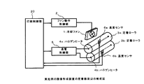
図3は実施例1の定着器18周辺の構成を示す図である。同図に示したように、実施例1の定着器18は、定着ローラ3a、3bを冷却する冷却ファン1、冷却ファン1の動作を制御するファン動作制御部2、上部の加熱ローラである定着ローラ3aと当該定着用発熱手段であるハロゲンヒータ4a、同様に下部の加熟ローラである定着ローラ3bと当該定着用発熱手段であるハロゲンヒータ4b、前記上下のハロゲンヒータ4aおよび4bへの通電制御を行う通電制御部5、定着ローラ3a、3bの温度をそれぞれ検出する温度センサ6a、6bおよび定着器を回転駆動する図示しないモータからなる。
(Fixer configuration)
FIG. 3 is a diagram illustrating a configuration around the fixing device 18 according to the first exemplary embodiment. As shown in the figure, the fixing device 18 of the first embodiment includes a cooling
上部の定着ローラ3aには図示しないモータが接続されており、印刷制御部20からの指示により正転、逆転または停止する。下部の定着ローラ3bは上部の定着ローラ3aに加圧されて接しており、連れ回りにより上部の定着ローラ3aにあわせて逆転、正転または停止するようになっている。
A motor (not shown) is connected to the upper fixing roller 3a, and forwardly, reversely, or stop according to an instruction from the
そして、上下の定着ローラ3a、3bにはそれぞれローラ表面温度を検出するサーミスタ等の温度センサ6a、6bが当接されており、その出力が印刷制御部20に接続されており、上下の定着ローラ3a、3bの表面の温度をそれぞれ独立して検出することができるようになっている。
The upper and lower fixing rollers 3a and 3b are respectively in contact with temperature sensors 6a and 6b such as a thermistor for detecting the roller surface temperature, and their outputs are connected to the
なお、前記定着ローラ3a、3bの表面温度検出手段としては、接触型のサーミスタではなく熱放射光の波長を非接触に検出して温度を抽出する温度センサなどを用いても勿論よい。 As the surface temperature detecting means of the fixing rollers 3a and 3b, it is of course possible to use not a contact type thermistor but a temperature sensor that detects the wavelength of the heat radiation light in a non-contact manner and extracts the temperature.
また、前記ハロゲンヒータ4a、ハロゲンヒータ4bは、印刷制御図20に接続された通電制御手段5に接続されており、温度センサ6a、6bにより検出した各温度に基づき、それぞれ独立して制御することができるようになっている。 The halogen heater 4a and the halogen heater 4b are connected to the energization control means 5 connected to the printing control FIG. 20, and are controlled independently based on the temperatures detected by the temperature sensors 6a and 6b. Can be done.
以上のように、ハロゲンヒータ4a、ハロゲンヒータ4bはそれぞれ独立して温度制御可能であるが、便宜上、制御された上下の定着ローラ3a、3bの表面温度を、以下「定着器18の温度」という。なお、定着ローラ3a、3bの表面温度は、それぞれの温度が等しくなる温度まで制御した温度を定着器18の温度としてもよいし、定着ローラ3a、3bの表面温度を平均した温度を定着器18の温度としてもよい。 As described above, the temperature of the halogen heater 4a and the halogen heater 4b can be independently controlled. For convenience, the controlled surface temperatures of the upper and lower fixing rollers 3a and 3b are hereinafter referred to as “the temperature of the fixing device 18”. . Note that the surface temperature of the fixing rollers 3a and 3b may be the temperature of the fixing device 18 controlled to the temperature at which the respective temperatures become equal, or the temperature obtained by averaging the surface temperatures of the fixing rollers 3a and 3b. It is good also as temperature of.
或いは、上部または下部の定着ローラ3a、3bのいずれかを発熱手段を持たない加圧するだけの加圧ローラとした構成とした場合では、後述のファン停止温度条件等の補正は必要であるが、発熱手段を持った側の定着ローラの温度を定着器18の温度としてもよい。 Alternatively, when any one of the upper and lower fixing rollers 3a and 3b is configured to be a pressure roller that does not have a heating means and only pressurizes, correction of a fan stop temperature condition described later is necessary. The temperature of the fixing roller on the side having the heat generating means may be the temperature of the fixing device 18.
なお、以上の説明では、発熱手段としてハロゲンヒータを用いた例を示したが、定着ローラを加熱する手段であればハロゲンヒータでなくてもよい。 In the above description, an example in which a halogen heater is used as the heat generating means has been described. However, a halogen heater may not be used as long as it is a means for heating the fixing roller.
また、以上の説明では、冷却ファン1を上部の定着ローラ3a側に配置している例を示したが、下部の定着ローラ3b側、或いは上下の定着ローラ3a、3bの中間位置あたりで記録媒体30の搬送路に干渉しない位置に配置するようにしてもよい。
In the above description, an example in which the cooling
(印刷動作)
以上の構成により、実施例1の画像形成装置の印刷動作は、以下のように行われる。まず、図示しない画像処理部が、例えばビットマップ形式の印刷データを一元的に配列したデータとして形成し、制御信号により画像形成装置に印刷を指示すると共に、前記印刷データをビデオ信号として印刷制御部20に供給する。
(Printing operation)
With the above configuration, the printing operation of the image forming apparatus according to the first exemplary embodiment is performed as follows. First, an image processing unit (not shown) forms, for example, bitmap-format print data as unified data, instructs the image forming apparatus to print using a control signal, and prints the print data as a video signal. 20 is supplied.
印刷制御部20は、制御信号により情報処理装置からの印刷指示を検出すると、まず、定着器温度センサ6a、6bによりハロゲンヒータ4a、4bを内蔵した定着ローラ3a、3bからなる定着器18が印刷可能温度範囲にあるか否かを検出し、印刷可能温度範囲になければ、ハロゲンヒータ4a、4bに通電して印刷可能温度範囲まで定着器18を加熱する。
When the
次に、印刷制御部20は、駆動部25を介し現像・転写プロセス用モータ10を回転させ、さらに、チャージ信号SGCを有効とし帯電用高圧電源27を動作させることにより帯電器8に電圧を印加して、感光ドラム22表面を帯電させる。
Next, the
そして、印刷制御部20は、媒体残量センサ14、媒体サイズセンサ15によって画像形成装置にセットされている記録媒体30の有無および種類を検出し、印刷に使用する記録媒体30の存在を検出すると、駆動部26を介し媒体送りを開始させる。なお、媒体送りモータ11は双方向に回転させることができ、媒体送りを開始する際には、最初に、媒体送りモータ11を逆回転させて、媒体吸入ロセンサ12が記録媒体30を検出するまで、セットされた記録媒体を規定量搬送する。
When the
そして、媒体送りモータ11を正回転させて記録媒体30を画像形成装置内部の印刷機構内に搬送する。印刷制御部20は、記録媒体30が印刷可能位置まで到達したときに、画像処理部に主走査同期信号、副走査同期信号を含む図示しないタイミング信号を供給する。
Then, the medium feeding motor 11 is rotated forward to convey the recording medium 30 into a printing mechanism inside the image forming apparatus. When the recording medium 30 reaches the printable position, the
すると、画像処理部は、前述のように印刷データを1元的に配列して形成したデータをビデオ信号とし、タイミング信号に同期させて、印刷ラインごとに印刷制御部20に供給する。
Then, the image processing unit supplies the data formed by arranging the print data in a unified manner as described above as a video signal, and supplies it to the
すると、印刷制御部20は、供給されたビデオ信号を印刷データ信号DATAとして別途発生したクロック信号CLKに同期させ、順次、露光部19に供給する。そして、1ライン分の印刷データ信号DATAの供給が終了すると印刷制御部20は露光部19に供給するロード信号LOADを、所定の時間、有効(ハイレベル)とし、印刷データ信号DATAに応じた印刷データを露光部19内に保持させる。
Then, the
そして、印刷制御部19は、印刷データが露光部19に保持された後、ストローブ信号STB−Nを、所定の時間、有効(ローレベル)とする。このストローブ信号STB−Nは、露光部19内に保持された印刷データに応じた露光部19の駆動制御のために用いられている。露光部19は、このストローブ信号STB−Nがローレベルであるときに、保持している印刷データに応じて露光部19の各LED素子を駆動して記録光を発生させる。
Then, after the print data is held in the
前記各LED素子が発光した記録光は、帯電器8によって負電位に帯電させられた感光ドラム22に照射され、各々のLED素子に対応する照射スポットが電位の上昇したドットとして潜像化される。そして、現像部24において、負電位に帯電させられた画像形成用のトナー24dが、電気的な吸引力によって各ドットに吸引され、トナー像が形成される。 The recording light emitted from each LED element is applied to the photosensitive drum 22 charged to a negative potential by the charger 8, and the irradiation spot corresponding to each LED element is formed into a latent image as a dot having an increased potential. . Then, in the developing unit 24, the image forming toner 24d charged to a negative potential is attracted to each dot by an electrical attraction force to form a toner image.
そして、形成されたトナー像は、感光ドラム22の回転によって転写器9に対向する位置に送られると、転写信号SG4によって動作を開始した転写用高圧電源28により負の電圧が印加された転写器9と感光ドラム22の間隙を通過する記録媒体30に転写される。
Then, when the formed toner image is sent to a position facing the transfer device 9 by the rotation of the photosensitive drum 22, the transfer device to which a negative voltage is applied by the transfer high-
そして、トナー像が転写された記録媒体30が、定着器18の定着ローラ3a、3bに当接して搬送されると、トナー像が定着器18の熱によって記録媒体30に定着される。トナー像が定着させられた記録媒体30は、さらに搬送されてプリンタの印刷機構から媒体排出ロセンサ13を通過してプリンタ外部に排出される。
When the recording medium 30 to which the toner image has been transferred is conveyed in contact with the fixing rollers 3 a and 3 b of the fixing device 18, the toner image is fixed to the recording medium 30 by the heat of the fixing device 18. The recording medium 30 on which the toner image is fixed is further conveyed and discharged from the printing mechanism of the printer through the
そして、印刷制御部20は、媒体サイズセンサ15、媒体吸入ロセンサ12の検知に対応じて、記録媒体30が転写器9を通過している間だけ転写用高圧電源28からの電圧を転写器9に印加する。そして、印刷が終了し、記録媒体30が媒体排出ロセンサ13を通過すると、帯電用高圧電圧27による帯電器8への電圧の印加を終了し、同時に現像・転写プロセス用モータ10の回転を停止させる。
Then, in response to detection by the
(定着器の動作)
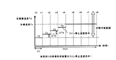
一方、前記構成により、実施例1の画像形成装置の定着器は以下のように動作する。まず、実施例1の画像形成装置では、図4に示したように、印刷可能温度範囲の下限温度T0を起点とし、あらかじめ決めた所定の時間Δtごとに所定の温度△Tdだけ増加させ、徐々に目標温度Txに近づくように冷却ファン停止温度条件を設定する。
(Fixer operation)
On the other hand, with the above configuration, the fixing device of the image forming apparatus according to the first exemplary embodiment operates as follows. First, in the image forming apparatus according to the first embodiment, as shown in FIG. 4, starting from the lower limit temperature T0 of the printable temperature range, the temperature is gradually increased by a predetermined temperature ΔTd every predetermined time Δt. The cooling fan stop temperature condition is set so as to approach the target temperature Tx.
ここで、図4の印刷可能範囲の下限温度T0では、4回の温度増加により目標温度Txに到達しているが、図5のように印刷可能温度範囲の下限温度T0が低くてよい場合では、6回の増加により目標温度Txに到達するように設定することになる。 Here, at the lower limit temperature T0 of the printable range in FIG. 4, the target temperature Tx is reached by four temperature increases, but in the case where the lower limit temperature T0 of the printable temperature range may be low as shown in FIG. In this case, the target temperature Tx is set to reach the target temperature Tx by 6 increases.
なお、図4、図5では、印刷終了時からファン冷却最大継続時間tmaxをΔt×8経過する時、すなわちt8までとしているが、Δt×8より大きくしてもよいし、逆に小さくしてもよい。また、前記印刷可能範囲の下限温度T0は、熱容量による加熱および冷却制御の遅れや検出センサの精度を考慮し、実際の限界値ではなく若干マージンを考慮した温度とするのがよい。 In FIGS. 4 and 5, the maximum fan cooling duration tmax is Δt × 8 after the end of printing, that is, up to t8. However, it may be larger than Δt × 8 or smaller. Also good. In addition, the lower limit temperature T0 of the printable range is preferably a temperature that takes into account a margin rather than an actual limit value in consideration of delays in heating and cooling control due to heat capacity and accuracy of the detection sensor.
以上のように設定した冷却ファン停止温度条件に基づき、実施例1の画像形成装置では、以下に述べるように、定着器18の温度制御を行う。 Based on the cooling fan stop temperature condition set as described above, the image forming apparatus according to the first embodiment performs temperature control of the fixing unit 18 as described below.
(熱量をあまり奪われない場合)
図6は、以上のように設定された冷却ファン停止温度条件により、定着器18の温度制御を行う一例である。本例では、まず、ハロゲンヒータ4a、4bをオンし、温度センサ6a、6bにより定着器18の温度Tdを検出し、定着器18の温度Tdが印刷可能温度範囲であることを確認すると、定着モータをオンし印刷を開始する(タイミングta)。そして、媒体排出口センサ13により印刷の終了を検出すると、冷却ファン1の回転を開始させる(タイミングtb)。
(If you don't lose much heat)
FIG. 6 shows an example of controlling the temperature of the fixing device 18 according to the cooling fan stop temperature condition set as described above. In this example, first, the halogen heaters 4a and 4b are turned on, the temperature sensors 6a and 6b detect the temperature Td of the fixing device 18, and it is confirmed that the temperature Td of the fixing device 18 is within the printable temperature range. The motor is turned on and printing is started (timing ta). When the medium
ハロゲンヒータ4a、4bをオンしながら印刷・定着を行うが、記録媒体30により熱量を奪われるため、定着器18の温度Tdは、図のように徐々に低下している。印刷枚数が少ない或いは薄い媒体を印刷する場合では、あまり熱量を奪われないので温度の低下は少ない。 Printing and fixing are performed while the halogen heaters 4a and 4b are turned on. However, since the amount of heat is deprived by the recording medium 30, the temperature Td of the fixing device 18 gradually decreases as shown in the figure. In the case of printing a small number of printed sheets or a thin medium, the amount of heat is not taken so much, so that the temperature decrease is small.
そして、印刷を終了すると、ハロゲンヒータ4a、4bをオフするが、定着器18は引続き熱容量による蓄熱で温度が上昇するため、冷却ファン1の回転を開始する(タイミングtb)。
When the printing is finished, the halogen heaters 4a and 4b are turned off. However, since the temperature of the fixing device 18 continues to rise due to heat accumulation by the heat capacity, the cooling
そして、前述のように、定着器18の温度Tdが印刷終了後の経過時間ごとに冷却ファン停止温度として設定した温度以下となったときに、冷却ファン1の回転を停止する(タイミングtc)。
As described above, the rotation of the cooling
以上のように制御することにより、冷却ファンを用いない従来の制御の場合では、オーバーシュートが発生し破線A’のように印刷可能温度範囲を越えてしまう場合であっても、実施例1の制御によれば、実線Aのように定着器18の温度Tdを推移させて印刷可能温度範囲とすることができ、次の印刷開始までの待ち時間をなくすことができる。 By performing the control as described above, in the case of the conventional control that does not use the cooling fan, even if the overshoot occurs and the printable temperature range is exceeded as indicated by the broken line A ′, According to the control, the temperature Td of the fixing device 18 can be changed as shown by the solid line A to be within the printable temperature range, and the waiting time until the next printing can be eliminated.
なお、前記ファン冷却最大継続時間tmaxだけ冷却し続けても、定着器18の温度Tdが冷却ファン停止温度以下とならない場合は、定着器18を冷却しすぎ温度が下がりすぎることがあるため、冷却ファン1の回転を停止するのがよい。
If the temperature Td of the fixing device 18 does not become equal to or lower than the cooling fan stop temperature even if the cooling is continued for the maximum fan cooling duration tmax, the temperature of the fixing device 18 may be excessively decreased. It is preferable to stop the rotation of the
(熱量を多く奪われる場合)
図7は、前記冷却ファン停止温度条件の設定方法により、定着器18の温度制御を行った別の例である。本例においても、まず、ハロゲンヒータ4a、4bをオンし、温度センサ6a、6bにより定着器18の温度Tdを検出し、定着器18の温度Tdが印刷可能温度範囲であることを確認すると、定着モータをオンし印刷を開始する(タイミングta)。そして、媒体排出口センサ13により印刷の終了を検出すると、冷却ファン1の回転を開始させる(タイミングtb)。
(If you lose a lot of heat)
FIG. 7 shows another example in which the temperature control of the fixing device 18 is performed by the method for setting the cooling fan stop temperature condition. Also in this example, when the halogen heaters 4a and 4b are first turned on, the temperature sensors 6a and 6b detect the temperature Td of the fixing device 18, and it is confirmed that the temperature Td of the fixing device 18 is within the printable temperature range. The fixing motor is turned on to start printing (timing ta). When the medium
ハロゲンヒータ4a、4bをオンしながら印刷および定着を行うが、記録媒体30により熱量を奪われるため、定着器18の温度Tdは、同図のように徐々に低下する。この場合、印刷枚数が多い或いは厚い記録媒体30を印刷すると、同図に示すように多くの熱量を奪われるので温度の低下が激しくなる。 Printing and fixing are performed while the halogen heaters 4a and 4b are turned on. However, since the amount of heat is deprived by the recording medium 30, the temperature Td of the fixing device 18 gradually decreases as shown in FIG. In this case, if the recording medium 30 having a large number of printed sheets or a thick recording medium 30 is printed, a large amount of heat is lost as shown in FIG.
そして、印刷を終了すると、ハロゲンヒータ4a、4bをオフし、定着器18が、引続き熱容量による蓄熱で温度が上昇するため、冷却ファン1の回転を開始する(タイミングtb)。
When the printing is finished, the halogen heaters 4a and 4b are turned off, and the fixing device 18 continues to rise in temperature due to heat storage by the heat capacity, so that the cooling
そして、前述のように、定着器18の温度Tdが印刷終了後の経過時間ごとに冷却ファン停止温度条件として設定した温度以下になったときに、冷却ファン1の回転を停止する(タイミングtc)。
As described above, the rotation of the cooling
以上のように制御することにより、印刷ページが多い場合等で熱量を多く奪われる場合などのように破線B’のように印刷可能温度範囲を越えて温度が低下してしまう場合であっても、実施例1の制御によれば、実線Bのように定着器18の温度Tdを推移させ、印刷可能温度範囲とすることができ、次の印刷を待機時間なく開始することができる。 Even if the temperature drops beyond the printable temperature range as indicated by the broken line B ′, such as when there is a large number of printed pages and a large amount of heat is lost by controlling as described above. According to the control of the first embodiment, the temperature Td of the fixing device 18 can be changed as indicated by the solid line B to be within the printable temperature range, and the next printing can be started without waiting time.
(実施例1の効果)
以上詳細に述べたように、実施例1の画像形成装置によれば、印刷終了からの経過時間に応じた冷却ファンの停止温度条件を設定し、当該温度条件以下に定着器温度が低下したときに、冷却ファンを停止するようにしたので、定着器の温度を確実に印刷可能温度の範囲内とすることができ、次の印刷までの待ち時間をなくすことができる。
(Effect of Example 1)
As described above in detail, according to the image forming apparatus of the first embodiment, when the cooling fan stop temperature condition is set according to the elapsed time from the end of printing and the fixing device temperature falls below the temperature condition. In addition, since the cooling fan is stopped, the temperature of the fixing device can be surely set within the printable temperature range, and the waiting time until the next printing can be eliminated.
実施例2の画像形成装置は、印刷終了後の経過時間に応じて冷却ファンの停止温度条件および冷却ファンの回転を再開する冷却ファン回転再開温度条件を設けたものである。 The image forming apparatus according to the second embodiment is provided with a cooling fan stop temperature condition and a cooling fan rotation restart temperature condition for restarting the cooling fan according to the elapsed time after the end of printing.
(構成)
実施例2の画像形成装置の制御系プロック図、構成図および定着器の構成図は、実施例1の図1ないし図3と同様であるので、簡略化のためにその説明を省略する。
(Constitution)
Since the control system block diagram, the configuration diagram, and the configuration diagram of the fixing device of the image forming apparatus of the second embodiment are the same as those of FIGS. 1 to 3 of the first embodiment, description thereof is omitted for simplification.
(印刷動作)
実施例2の印刷動作は、実施例1の画像形成装置の印刷動作と同様であるので、簡略化のために、その説明を省略する。
(Printing operation)
Since the printing operation of the second embodiment is similar to the printing operation of the image forming apparatus of the first embodiment, the description thereof is omitted for the sake of brevity.
(定着器の動作)
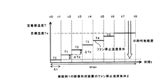
図8は、実施例2の画像形成装置のファン停止・再開温度条件と定着器18の動作を示すグラフであり、横軸は印刷終了時からの経過時間tを表し、縦軸は定着器の温度Tdを表している。そして、同図の実線および破線は、以下に説明する動作により設定するものであり、それぞれ冷却ファン1の回転を停止させる温度条件、冷却ファン1の回転を再開させる温度条件を表している。
(Fixer operation)
FIG. 8 is a graph showing the fan stop / restart temperature conditions and the operation of the fixing unit 18 of the image forming apparatus of Example 2. The horizontal axis represents the elapsed time t from the end of printing, and the vertical axis represents the fixing unit. It represents the temperature Td. The solid line and the broken line in the figure are set by the operations described below, and represent a temperature condition for stopping the rotation of the cooling
すなわち、実施例2の画像形成装置では、同図に示したように印刷可能範囲の下限温度T0を起点とし、あらかじめ決めた所定の時間Δtごとに所定の温度△Td増加させ、徐々に目標温度Txに近づくように冷却ファン停止温度条件を設定する。 That is, in the image forming apparatus according to the second embodiment, as shown in the figure, the lower limit temperature T0 of the printable range is set as a starting point, the predetermined temperature ΔTd is increased every predetermined time Δt, and the target temperature is gradually increased. The cooling fan stop temperature condition is set so as to approach Tx.
同様に、印刷可能範囲の下限温度T0に所定の温度、本例では2*△Tdを加算した温度T0’を起点として、あらかじめ決めた所定の時間Δtごとに所定の温度△Td’増加させ冷却ファン再開温度条件を設定する。 Similarly, starting from a temperature T0 ′ obtained by adding a predetermined temperature to the lower limit temperature T0 of the printable range, in this example, 2 * ΔTd, cooling is performed by increasing the predetermined temperature ΔTd ′ every predetermined time Δt. Set the fan restart temperature condition.
なお、冷却ファン再開温度条件を、前述のようにT0’を起点として所定の時間Δtごとに所定の温度△Td’増加させるのではなく、前述冷却ファン停止温度条件に一定の温度を加算して設定するようにしてもよい。 The cooling fan restart temperature condition is not increased by a predetermined temperature ΔTd ′ every predetermined time Δt starting from T0 ′ as described above, but a certain temperature is added to the cooling fan stop temperature condition. You may make it set.
或いは、冷却ファン再開温度条件を、所定の時間Δtごとに所定の温度△Td’分増加させるのではなく、徐々に増加させる温度を少なくし、目標温度Txに近づくように冷却ファン停止温度を設定するようにしてもよい。 Alternatively, instead of increasing the cooling fan restart temperature condition by a predetermined temperature ΔTd ′ every predetermined time Δt, the temperature to be gradually increased is decreased and the cooling fan stop temperature is set so as to approach the target temperature Tx. You may make it do.
ここで、図8の場合の印刷可能範囲の下限温度T0では、4回の温度増加により目標温度Txに到達しているが、実施例1にて説明した図5のように印刷可能範囲の下限温度T0が低くてよい場合では、冷却ファン停止温度条件は6回の増加により目標温度Txに到達するように設定することになることになる。このとき、実施例2では、冷却ファン再開温度条件も同様に6回となる。 Here, at the lower limit temperature T0 of the printable range in the case of FIG. 8, the target temperature Tx is reached by the temperature increase four times, but the lower limit of the printable range as shown in FIG. In the case where the temperature T0 may be low, the cooling fan stop temperature condition is set to reach the target temperature Tx by an increase of 6 times. At this time, in Example 2, the cooling fan resumption temperature condition is also 6 times.
また、実施例2の画像形成装置では、図8のように、印刷終了時からファン冷却最大継続時間tmaxをΔt×8経過する時、すなわちt8までとしているが、t8より大きく或いは逆に小さくするようにしてもよいことは実施例1と同様である。また、前記印刷可能範囲の下限温度T0は、熱容量による加熱および冷却制御の遅れや検出センサの精度を考慮し、実際の限界値ではなく若干マージンを考慮した温度とするのがよい。 Further, in the image forming apparatus according to the second embodiment, as shown in FIG. 8, the maximum fan cooling duration tmax is Δt × 8 after the end of printing, that is, until t8, but is larger or smaller than t8. This may be the same as in the first embodiment. In addition, the lower limit temperature T0 of the printable range is preferably set to a temperature that considers a margin rather than an actual limit value in consideration of delays in heating and cooling control due to heat capacity and accuracy of the detection sensor.
次に、以上のように設定した冷却ファン停止温度に基づき、印刷終了後の定着器18の温度Tdが、前記冷却ファン停止温度条件以下となったときに冷却ファン1の回転を停止し、その後、冷却ファン再開温度条件以上となったときに冷却ファン1の回転を再開させるようにする。以下、この動作を詳細に説明する。
Next, based on the cooling fan stop temperature set as described above, the rotation of the cooling
すなわち、印刷終了後、印刷制御部20はオーバーシュートを抑えるために冷却ファン1を回転させる(タイミングt0)。印刷制御部20は定着器18の温度Tdを温度センサ6a、6bにより検出して、ファン停止温度条件以下となるまで冷却ファン1の回転を継続させる。
That is, after the printing is finished, the
そして、ファン停止温度条件以下となったとき、すなわち本例では温度T2以下となったとき、印刷制御部20は冷却ファン1の回転を停止し(タイミングtd)、再び定着器18の温度Tdが上昇しファン冷却再開条件温度以上となったとき、すなわち本例では温度T2’以上となったとき、冷却ファン1の回転を再開させて定着ローラ5の冷却を再開する(タイミングte)。
When the temperature is lower than the fan stop temperature condition, that is, when the temperature is lower than T2 in this example, the
そして、冷却ファン1により冷却され定着器18の温度Tdが下がりファン停止温度条件、すなわち本例では、温度T3以下となったとき冷却ファン1の回転を停止する(タイミングtf)。
Then, when the temperature Td of the fixing device 18 is cooled by the cooling
以上の動作を印刷終了(タイミングt0)からファン冷却最大継続時間tmaxまで繰り返す。これにより、図8に示したように、定着器18の温度Tdを、ファン停止温度条件とファン再開温度条件の範囲内とすることができる。 The above operation is repeated from the end of printing (timing t0) to the maximum fan cooling duration tmax. Thereby, as shown in FIG. 8, the temperature Td of the fixing device 18 can be set within the range of the fan stop temperature condition and the fan restart temperature condition.
図9は、定着器18の熱容量や印刷する枚数等により奪われる熱量が異なる場合において、実施例2の温度制御の方法により定着器18の温度Tdを制御した結果を示したものである。 FIG. 9 shows the result of controlling the temperature Td of the fixing device 18 by the temperature control method of the second embodiment when the amount of heat taken away depends on the heat capacity of the fixing device 18 and the number of printed sheets.
すなわち、実施例2の温度制御の方法によれば、図9下側に記載した印刷終了のタイミングtu0にて冷却ファン1をオンし、続くタイミングtu1ないしtu6において、交互に、ファン停止温度条件以下、ファン再開温度条件以上となるので、冷却ファン1をそれぞれオフ、オンを繰り返し図中実線のCのように定着器18の温度Tdが制御されることになる。
That is, according to the temperature control method of the second embodiment, the cooling
以上の制御結果から分かるように、実施例2の定着器18の温度制御方法によれば、図中C’のように定着器18の蓄熱量が多い場合或いは印刷枚数が少なくあまり熱量を奪われないときの急激なオーバーシュートの発生により印刷可能温度範囲以上となる場合や、図中C”のように定着器18の蓄熱量が少ない場合或いは印刷枚数が多く多量の熱量を奪われアンダーシュートが発生する場合であっても、確実に印刷温度範囲内となるように制御することができる。 As can be seen from the above control results, according to the temperature control method of the fixing device 18 of the second embodiment, when the heat storage amount of the fixing device 18 is large as shown by C ′ in the drawing or the number of printed sheets is small, the heat amount is deprived. When the temperature exceeds the printable temperature range due to the occurrence of a sudden overshoot when there is not, or when the heat storage amount of the fixing device 18 is small as shown by C "in the figure or when the number of printed sheets is large and a large amount of heat is taken away, an undershoot occurs. Even if it occurs, it can be controlled to be surely within the printing temperature range.
(実施例2の効果)
以上詳細に述べたように、実施例2の画像形成装置によれば、印刷終了からの経過時間に応じた冷却ファンの停止温度条件および冷却ファンの回転を再開する冷却ファン回転再開温度条件を設けて定着器18の温度Tdを制御するようにしたので、定着器の蓄熱量が変化或いは印刷枚数等が変化しても、定着器の温度を確実に印刷可能温度範囲とすることができ、次の印刷開始までの待ち時間が発生することがない。
(Effect of Example 2)
As described above in detail, according to the image forming apparatus of the second embodiment, the cooling fan stop temperature condition according to the elapsed time from the end of printing and the cooling fan rotation restart temperature condition for restarting the cooling fan are provided. Since the temperature Td of the fixing device 18 is controlled, even if the heat storage amount of the fixing device or the number of printed sheets changes, the temperature of the fixing device can be surely set within the printable temperature range. There is no waiting time until the start of printing.
実施例3の画像形成装置は、経過時間に応じた冷却ファンの回転を減速する温度および冷却ファンの回転を増加する温度条件を設け、印刷終了後の時間と定着器の温度に応じファンの回転数を変化させるようにしたものである。 The image forming apparatus according to the third exemplary embodiment has a temperature condition for decelerating the rotation of the cooling fan according to the elapsed time and a temperature condition for increasing the rotation of the cooling fan, and the rotation of the fan according to the time after printing and the temperature of the fixing device. The number is changed.
(構成)
実施例3の画像形成装置の制御系ブロック図、構成図および定着器の構成図は、実施例1の図1ないし図3と同様であるので、簡略化のためにその説明を省略する。
(Constitution)
A control system block diagram, a configuration diagram, and a configuration diagram of the fixing device of the image forming apparatus according to the third exemplary embodiment are the same as those illustrated in FIGS. 1 to 3 of the first exemplary embodiment, and thus the description thereof is omitted for simplification.
(印刷動作)
印刷動作は、実施例1や実施例2の画像形成装置の印刷動作と同様であるので、簡略化のために、その説明を省略する。
(Printing operation)
Since the printing operation is the same as the printing operation of the image forming apparatus according to the first embodiment or the second embodiment, the description thereof is omitted for the sake of brevity.
(定着器の動作)
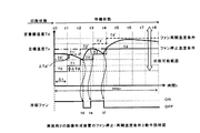
図10は、実施例3の画像形成装置のファン減速・加速温度条件と動作説明図である。図8と同様に横軸は印刷終了時からの経過時問を、縦軸は定着器18の温度Tdを表している。本例では、図10中の実線が冷却ファン1の回転数を下げる方向とする設定温度であり、破線が冷却ファン1の回転数を上げる方向とする設定温度である。
(Fixer operation)
FIG. 10 is an explanatory diagram of fan deceleration / acceleration temperature conditions and operation of the image forming apparatus according to the third embodiment. As in FIG. 8, the horizontal axis represents the elapsed time from the end of printing, and the vertical axis represents the temperature Td of the fixing device 18. In this example, the solid line in FIG. 10 is the set temperature that sets the rotation speed of the cooling
前記ファン減速温度条件およびファン加速温度条件は、図8を用いて説明した実施例2のファン停止温度条件およびファン再開温度条件と同様であるので、簡略化のためにその説明を省略する。 Since the fan deceleration temperature condition and the fan acceleration temperature condition are the same as the fan stop temperature condition and the fan restart temperature condition of the second embodiment described with reference to FIG. 8, the description thereof is omitted for simplification.
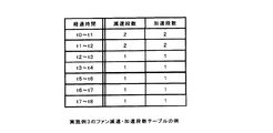
実施例3の画像形成装置では、図11に示したように印刷終了後の経過時間ごとにあらかじめ冷却ファン1を減速する段数或いは加速する段数を設定し、印刷制御部20のメモリ等に格納して置く。例えば、印刷終了後、t2〜t3時間の間に、定着器18の温度Tdがファン減速温度条件以下に下がり、冷却ファン1を減速する場合は、当該テーブルよりt2〜t3時間の減速段数を参照すると“2”が抽出されるので、冷却ファン1の回転数を2段下げることになる。
In the image forming apparatus according to the third embodiment, as shown in FIG. 11, the number of stages for decelerating or accelerating the cooling
再び、図10に戻って、印刷終了時点の定着器18の温度Tdに応じて設定したファン減速温度条件およびファン加速温度条件に基づき、印刷制御部20は、以下のように定着器18の温度Tdを制御する。
Referring back to FIG. 10 again, based on the fan deceleration temperature condition and the fan acceleration temperature condition set according to the temperature Td of the fixing device 18 at the end of printing, the
すなわち、印刷制御部20は、印刷を終了すると(タイミングt0)、定着器18の温度Tdを温度センサ6a、6bにより検出し、検出された温度が実線で示されるファン減速温度条件以下となったとき、前述図11のテーブルに従い、経過時間ごとに設定された回転数までファンの回転数を下げる(タイミングtg)。本例の場合では、t1〜t2間においてファン減速温度条件以下となっているので2段階回転数を下げる。 That is, when printing is finished (timing t0), the temperature Td of the fixing device 18 is detected by the temperature sensors 6a and 6b, and the detected temperature falls below the fan deceleration temperature condition indicated by the solid line. At this time, the rotational speed of the fan is lowered to the rotational speed set for each elapsed time according to the table of FIG. 11 (timing tg). In the case of this example, since it is below the fan deceleration temperature condition between t1 and t2, the two-stage rotational speed is lowered.
また、破線で示されるファン加速温度条件以上となったときは、経過時間毎に設定された回転数まで冷却ファン1の回転数を上げるように制御することになるが、本例においては、ファン加速温度条件まで達していないので、冷却ファン1の回転を加速することなく、冷却ファン回転数OFFまで順次減速するようになっている。
Further, when the temperature exceeds the fan acceleration temperature condition indicated by the broken line, control is performed to increase the rotation speed of the cooling
以上の動作を印刷終了(タイミングt0)からファン冷却最大継続時間tmaxまで繰り返す。これにより、図10に示したように、定着器18の温度Tdを、ファン停止温度条件とファン再開温度条件の範囲内とすることができる。 The above operation is repeated from the end of printing (timing t0) to the maximum fan cooling duration tmax. Thereby, as shown in FIG. 10, the temperature Td of the fixing device 18 can be set within the range of the fan stop temperature condition and the fan restart temperature condition.
図12は、定着器18の熱容量や印刷する枚数等により奪われる熱量が異なる場合において、実施例3の温度制御の方法により定着器18の温度Tdを制御した結果を示したものである。 FIG. 12 shows the result of controlling the temperature Td of the fixing device 18 by the temperature control method of the third embodiment when the amount of heat taken away depends on the heat capacity of the fixing device 18 and the number of printed sheets.
すなわち、図12の下側に記載した印刷終了のタイミングt0にて冷却ファン1の回転数を最大の「4」とし、続くタイミングtgないしtiにより徐々に、冷却ファン1の回転数を下げて冷却制御を行う。このようにファンの回転を制御することにより、図中実線のCのように定着器18の温度Tdが滑らかに制御され、確実に印刷温度範囲内となるように制御される。
That is, the rotation speed of the cooling
以上の制御結果から分かるように、実施例3の定着器18の温度制御方法によれば、図中D’のように定着器18の蓄熱量が多い場合或いは印刷枚数が少なくあまり熱量を奪われないときの急激なオーバーシュートの発生により印刷可能温度範囲以上となる場合であっても、図中D”のように定着器18の蓄熱量が少ない場合或いは印刷枚数が多く多量の熱量を奪われアンダーシュートが発生する場合であっても、確実に印刷温度範囲内となるように制御することができる。 As can be seen from the above control results, according to the temperature control method of the fixing device 18 of the third embodiment, when the heat storage amount of the fixing device 18 is large as shown by D ′ in the drawing or the number of printed sheets is small and the heat amount is deprived. Even when the temperature exceeds the printable temperature range due to the occurrence of a sudden overshoot when there is not, when the heat storage amount of the fixing device 18 is small as shown in D ”in the figure, or the number of printed sheets is large and a large amount of heat is taken away. Even if undershoot occurs, it can be controlled to be surely within the printing temperature range.
なお、以上の実施例3の説明では、冷却ファン1の回転数の段数を4段階として説明したが、4段階に限ることなく、さらに多段、或いは4段階より少ない段数としてもよい。或いは、多少処理が複雑になるが、冷却ファン1の回転数の切替えを1つの直線や複数の直線、或いは曲線で近似して制御するようにしてもよい。
In the above description of the third embodiment, the number of rotation speed stages of the cooling
(実施例3の効果)
印刷終了からの経過時間に応じた冷却ファンの回転を減速する温度条件および冷却ファン1の回転を増加する温度条件を設け、印刷終了後の時間と定着器18の温度に応じて冷却ファン1の回転数を可変とするようにし、実施例1や実施例2のようにオンオフ制御によらず回転数により制御するので、滑らかな制御をすることができる。その結果、定着器18の温度を確実に印刷可能温度範囲とすることができ、次の印刷開始までの待機時間が発生することがない。
(Effect of Example 3)
A temperature condition for decelerating the rotation of the cooling fan according to the elapsed time from the end of printing and a temperature condition for increasing the rotation of the cooling
《その他の変形例》
以上述べた実施例の他、以下の変形例の実施形態としても本発明の同様の作用、効果が得られる。すなわち、
<< Other modifications >>
In addition to the examples described above, the same functions and effects of the present invention can be obtained as embodiments of the following modifications. That is,
(1)実施例の画像形成装置の説明では、定着器18の温度Tdにより冷却ファン1の回転のオンオフ制御或いは回転数を制御するように説明したが、定着器18の温度Tdにより冷却の効果を変化させればよいので、例えば冷却ファン1と定着器18の距離を制御し冷却の効果を変化させるように制御してもよいし、或いは複数のファンを設け、各ファンのオンオフ制御或いは回転数の制御を行うようにしてもよいし、併せて行うようにしてもよい。
(1) In the description of the image forming apparatus according to the embodiment, it has been described that the on / off control of the rotation of the cooling
(2)また、実施例の画像形成装置の説明では、印刷装置内温度や定着器18近傍の温度湿度などによる影響については記載しなかったが、制御がやや複雑になるが、図1の温湿度センサ17の検出値に応じ、装置内温度或いは定着器18周辺の温度が高い場合は、冷却の効果が少なくなるので、ファン停止温度条件、ファン再開温度条件、ファン加速温度条件、ファン減速温度条件などの設定温度を一定値下げたり、一定の率で下げたりするようにしてもよい。
(2) In the description of the image forming apparatus according to the embodiment, the influence of the temperature inside the printing apparatus and the temperature and humidity in the vicinity of the fixing device 18 is not described. However, although the control is somewhat complicated, the temperature of FIG. If the temperature inside the apparatus or the temperature around the fixing device 18 is high according to the detection value of the
(3)また、実施例の説明では、あらかじめ決めた所定の時間Δtを一定の時間、増加させる所定の温度△Tdを一定の温度として説明したが、徐々にΔtを増加或いは減少させ、△Tdをそれに応じて変化させるようにしてもよいし、定着器18の温度に応じ、その間隔を変化させるなど、特に固定しない間隔としてもよい。或いは、ファン停止温度条件などを、時間tを変数とする1つの直線や複数の直線、或いは曲線により表して設定するようにしてもよい。 (3) In the description of the embodiment, the predetermined temperature ΔTd for increasing the predetermined time Δt for a predetermined time has been described as a constant temperature, but Δt is gradually increased or decreased to increase ΔTd. May be changed accordingly, or the interval may be changed according to the temperature of the fixing device 18, and the interval may not be particularly fixed. Alternatively, the fan stop temperature condition and the like may be set by being expressed by a single straight line, a plurality of straight lines, or a curve with the time t as a variable.
例えば、印刷可能温度範囲の下限温度T0、目標温度Tx、ファン冷却最大継続時間tmaxを用いて、ファン停止温度条件={(Tx−T0)/tmax}t+T0として表す。そして、印刷終了後の現時点での経過時間tにおけるファン停止温度条件を前式により算出し、算出した温度より定着器18の温度が下がったときにファンを停止するようにする。 For example, the fan stop temperature condition = {(Tx−T0) / tmax} t + T0 using the lower limit temperature T0, the target temperature Tx, and the maximum fan cooling duration tmax of the printable temperature range. Then, the fan stop temperature condition at the current elapsed time t after the end of printing is calculated according to the previous equation, and the fan is stopped when the temperature of the fixing device 18 falls below the calculated temperature.
実施例2や実施例3の場合などでは、さらにファン再開温度条件、ファン加速温度条件も同様に直線などで表し、同様に各条件を算出し、定着器18の温度と比較するようにすればよい。 In the case of the second embodiment and the third embodiment, the fan restart temperature condition and the fan acceleration temperature condition are similarly represented by straight lines, and each condition is calculated in the same manner and compared with the temperature of the fixing device 18. Good.
(4)また、実施例の説明では、冷却ファン1の回転を開始する印刷終了時について具体的に記載しなかったが、印刷終了としては、1ページの印刷終了の時点としてもよいし、1つの文書ファイルなどの印刷を終了する時点としてもよいし、印刷後情報処理装置から一定時間の間、印刷データの転送がない時を印刷終了として、定着器18の温度制御を開始するようにしてもよい。或いは、冷却ファン1を印刷終了時とは関係なく開始して置くようにしてよい。
(4) In the description of the embodiment, the end of printing for starting the rotation of the cooling
以上述べたように、本発明は、定着装置を備えた電子写真プリンタ、複写機等の画像形成装置に広く用いることができる。 As described above, the present invention can be widely used in image forming apparatuses such as electrophotographic printers and copying machines equipped with a fixing device.
1 冷却ファン
3 定着ローラ
4 ハロゲンヒータ
6 温度センサ
18 定着器
20 印刷制御部
DESCRIPTION OF
Claims (9)
前記定着手段を加熱する加熱手段と、
前記加熱手段により加熱された前記定着手段の温度を検出する温度検出手段と、
前記定着手段を冷却する冷却手段と、
前記加熱手段の駆動を制御する加熱制御手段と、
前記冷却手段の駆動を制御する冷却制御手段とを備え、
前記定着手段による定着が終了されると、前記温度検出手段により検出される温度が第1の温度以下であれば前記冷却制御手段は前記冷却手段の駆動を制限することを特徴とする画像形成装置。 Fixing means for fixing the developer image on the recording medium;
Heating means for heating the fixing means;
Temperature detecting means for detecting the temperature of the fixing means heated by the heating means;
A cooling means for cooling the fixing means;
Heating control means for controlling driving of the heating means;
Cooling control means for controlling the driving of the cooling means,
When the fixing by the fixing unit is finished, the cooling control unit restricts the driving of the cooling unit if the temperature detected by the temperature detecting unit is equal to or lower than a first temperature. .
前記定着手段を加熱する加熱手段と、
前記加熱手段により加熱された前記定着手段の温度を検出する温度検出手段と、
前記定着手段を冷却する冷却手段と、
前記加熱手段の駆動を制御する加熱制御手段と、
前記冷却手段の駆動を制御する冷却制御手段とを備え、
前記定着手段による定着が停止されると、前記冷却制御手段は前記冷却手段の駆動を開始し、前記温度検出手段により検出される温度が第1の温度以下であれば前記冷却制御手段は前記冷却手段の駆動を減速し、その後前記温度検出手段により検出される温度が第2の温度以上であれば前記冷却制御手段は前記冷却手段の駆動を加速させることを特徴とする画像形成装置。 Fixing means for fixing the developer image on the recording medium;
Heating means for heating the fixing means;
Temperature detecting means for detecting the temperature of the fixing means heated by the heating means;
A cooling means for cooling the fixing means;
Heating control means for controlling driving of the heating means;
Cooling control means for controlling the driving of the cooling means,
When fixing by the fixing unit is stopped, the cooling control unit starts driving the cooling unit, and if the temperature detected by the temperature detecting unit is equal to or lower than a first temperature, the cooling control unit The image forming apparatus according to claim 1, wherein the driving of the cooling unit is decelerated, and the cooling control unit accelerates the driving of the cooling unit if the temperature detected by the temperature detecting unit is equal to or higher than the second temperature.
Priority Applications (2)
| Application Number | Priority Date | Filing Date | Title |
|---|---|---|---|
| JP2004361950A JP4537841B2 (en) | 2004-12-14 | 2004-12-14 | Image forming apparatus |
| US11/283,904 US7187883B2 (en) | 2004-12-14 | 2005-11-22 | Image forming apparatus having fixing device with cooling device |
Applications Claiming Priority (1)
| Application Number | Priority Date | Filing Date | Title |
|---|---|---|---|
| JP2004361950A JP4537841B2 (en) | 2004-12-14 | 2004-12-14 | Image forming apparatus |
Publications (2)
| Publication Number | Publication Date |
|---|---|
| JP2006171237A true JP2006171237A (en) | 2006-06-29 |
| JP4537841B2 JP4537841B2 (en) | 2010-09-08 |
Family
ID=36584037
Family Applications (1)
| Application Number | Title | Priority Date | Filing Date |
|---|---|---|---|
| JP2004361950A Expired - Fee Related JP4537841B2 (en) | 2004-12-14 | 2004-12-14 | Image forming apparatus |
Country Status (2)
| Country | Link |
|---|---|
| US (1) | US7187883B2 (en) |
| JP (1) | JP4537841B2 (en) |
Cited By (4)
| Publication number | Priority date | Publication date | Assignee | Title |
|---|---|---|---|---|
| US7647015B2 (en) | 2007-03-30 | 2010-01-12 | Fuji Xerox Co., Ltd. | Color image forming apparatus and color image forming method |
| US8295727B2 (en) | 2009-03-17 | 2012-10-23 | Oki Data Corporation | Image forming apparatus with temperature adjustment |
| WO2018225874A1 (en) * | 2017-06-06 | 2018-12-13 | キヤノン株式会社 | Image heating device |
| JP2021004969A (en) * | 2019-06-26 | 2021-01-14 | 株式会社沖データ | Image forming apparatus, method for controlling image forming apparatus, and fixing device |
Families Citing this family (14)
| Publication number | Priority date | Publication date | Assignee | Title |
|---|---|---|---|---|
| JP2008026670A (en) * | 2006-07-21 | 2008-02-07 | Toshiba Corp | Image forming device, fixing device, and fixing device control method |
| JP4407740B2 (en) * | 2007-11-16 | 2010-02-03 | コニカミノルタビジネステクノロジーズ株式会社 | Bookbinding apparatus and image forming system |
| KR20090100830A (en) * | 2008-03-21 | 2009-09-24 | 삼성전자주식회사 | Method and apparatus for controlling transfer of paper |
| US7933530B2 (en) * | 2008-03-26 | 2011-04-26 | Lexmark International, Inc. | Fuser assembly fan control |
| US20090245838A1 (en) * | 2008-03-26 | 2009-10-01 | David William Shuman | Fuser heater temperature control |
| US8023851B2 (en) | 2008-07-18 | 2011-09-20 | Lexmark International, Inc. | Method and printer assembly for consistent power control in fuser assembly of electrophotographic printer |
| JP5424079B2 (en) * | 2008-08-21 | 2014-02-26 | 株式会社リコー | Fixing apparatus and image forming apparatus |
| JP2010054813A (en) * | 2008-08-28 | 2010-03-11 | Brother Ind Ltd | Image forming apparatus |
| JP5950796B2 (en) * | 2011-11-28 | 2016-07-13 | キヤノン株式会社 | Image forming apparatus |
| JP5852423B2 (en) * | 2011-12-01 | 2016-02-03 | キヤノン株式会社 | Image heating control device |
| JP5453504B1 (en) * | 2012-10-16 | 2014-03-26 | 株式会社東芝 | Image forming apparatus |
| JP2015135370A (en) * | 2014-01-16 | 2015-07-27 | ブラザー工業株式会社 | image forming apparatus |
| JP2016184012A (en) * | 2015-03-25 | 2016-10-20 | 富士ゼロックス株式会社 | Image forming apparatus |
| JP2017120294A (en) * | 2015-12-28 | 2017-07-06 | 株式会社沖データ | Image forming apparatus |
Citations (4)
| Publication number | Priority date | Publication date | Assignee | Title |
|---|---|---|---|---|
| JPH025079A (en) * | 1988-06-24 | 1990-01-09 | Canon Inc | Image forming device |
| JPH0394278A (en) * | 1989-09-06 | 1991-04-19 | Fuji Xerox Co Ltd | Cooling device for image forming device |
| JPH05323754A (en) * | 1992-05-19 | 1993-12-07 | Murata Mach Ltd | Image forming device |
| JP2001343857A (en) * | 2000-05-31 | 2001-12-14 | Konica Corp | Fixing device |
Family Cites Families (4)
| Publication number | Priority date | Publication date | Assignee | Title |
|---|---|---|---|---|
| DE3141464A1 (en) * | 1980-10-17 | 1982-04-29 | Canon Kk | "COPIER" |
| EP0534417B1 (en) * | 1991-09-24 | 1997-02-12 | Canon Kabushiki Kaisha | Image heating apparatus with multiple temperature detecting members |
| US6650863B2 (en) * | 2001-02-26 | 2003-11-18 | Konica Corporation | Fixing unit and image forming apparatus |
| US7054572B2 (en) * | 2003-03-31 | 2006-05-30 | Eastman Kodak Company | Method and apparatus for selective fuser rolling cooling |
-
2004
- 2004-12-14 JP JP2004361950A patent/JP4537841B2/en not_active Expired - Fee Related
-
2005
- 2005-11-22 US US11/283,904 patent/US7187883B2/en active Active
Patent Citations (4)
| Publication number | Priority date | Publication date | Assignee | Title |
|---|---|---|---|---|
| JPH025079A (en) * | 1988-06-24 | 1990-01-09 | Canon Inc | Image forming device |
| JPH0394278A (en) * | 1989-09-06 | 1991-04-19 | Fuji Xerox Co Ltd | Cooling device for image forming device |
| JPH05323754A (en) * | 1992-05-19 | 1993-12-07 | Murata Mach Ltd | Image forming device |
| JP2001343857A (en) * | 2000-05-31 | 2001-12-14 | Konica Corp | Fixing device |
Cited By (8)
| Publication number | Priority date | Publication date | Assignee | Title |
|---|---|---|---|---|
| US7647015B2 (en) | 2007-03-30 | 2010-01-12 | Fuji Xerox Co., Ltd. | Color image forming apparatus and color image forming method |
| US8295727B2 (en) | 2009-03-17 | 2012-10-23 | Oki Data Corporation | Image forming apparatus with temperature adjustment |
| WO2018225874A1 (en) * | 2017-06-06 | 2018-12-13 | キヤノン株式会社 | Image heating device |
| JPWO2018225874A1 (en) * | 2017-06-06 | 2020-04-23 | キヤノン株式会社 | Image heating device |
| US11144008B2 (en) | 2017-06-06 | 2021-10-12 | Canon Kabushiki Kaisha | Image heating apparatus having first and second cooling fans cooling an end portion of a first rotatable member |
| JP7114584B2 (en) | 2017-06-06 | 2022-08-08 | キヤノン株式会社 | image heating device |
| JP2021004969A (en) * | 2019-06-26 | 2021-01-14 | 株式会社沖データ | Image forming apparatus, method for controlling image forming apparatus, and fixing device |
| JP7243482B2 (en) | 2019-06-26 | 2023-03-22 | 沖電気工業株式会社 | IMAGE FORMING APPARATUS, IMAGE FORMING APPARATUS CONTROL METHOD, FIXING DEVICE |
Also Published As
| Publication number | Publication date |
|---|---|
| US20060127119A1 (en) | 2006-06-15 |
| JP4537841B2 (en) | 2010-09-08 |
| US7187883B2 (en) | 2007-03-06 |
Similar Documents
| Publication | Publication Date | Title |
|---|---|---|
| JP4537841B2 (en) | Image forming apparatus | |
| JP2941827B2 (en) | Recording device | |
| JP2002040870A (en) | Fixing device and image forming device provided with the same | |
| JP2002040873A (en) | Image forming device | |
| EP2645179A2 (en) | Image forming apparatus | |
| US9046836B2 (en) | Image forming apparatus for restricting excessive temperature rise of fixing member | |
| JPH07239647A (en) | Image forming device | |
| JP2005070119A (en) | Image forming apparatus | |
| JP2008268561A (en) | Image forming apparatus | |
| JP2007187833A (en) | Image forming apparatus and image forming method | |
| JP2002132087A (en) | Image forming device | |
| JP2007065413A (en) | Image forming apparatus | |
| JP2007156238A (en) | Motor controller and image forming apparatus | |
| JP2005134449A (en) | Image forming apparatus and its control method | |
| JP2003280447A (en) | Image forming apparatus | |
| JP2006126578A (en) | Image forming apparatus | |
| JP4636957B2 (en) | Image forming apparatus | |
| JP7006487B2 (en) | Image forming device | |
| JP4546154B2 (en) | Image forming apparatus | |
| JP2006162861A (en) | Image forming apparatus | |
| JP2008020533A (en) | Fixing device and image forming apparatus equipped therewith | |
| JP2009223235A (en) | Image forming apparatus | |
| JP2006154047A (en) | Image forming apparatus | |
| JPH0764434A (en) | Image forming device | |
| JP2019135527A (en) | Image forming apparatus |
Legal Events
| Date | Code | Title | Description |
|---|---|---|---|
| RD02 | Notification of acceptance of power of attorney |
Free format text: JAPANESE INTERMEDIATE CODE: A7422 Effective date: 20061025 |
|
| A621 | Written request for application examination |
Free format text: JAPANESE INTERMEDIATE CODE: A621 Effective date: 20070215 |
|
| A977 | Report on retrieval |
Free format text: JAPANESE INTERMEDIATE CODE: A971007 Effective date: 20091225 |
|
| A131 | Notification of reasons for refusal |
Free format text: JAPANESE INTERMEDIATE CODE: A131 Effective date: 20100112 |
|
| A521 | Written amendment |
Free format text: JAPANESE INTERMEDIATE CODE: A523 Effective date: 20100311 |
|
| A131 | Notification of reasons for refusal |
Free format text: JAPANESE INTERMEDIATE CODE: A131 Effective date: 20100330 |
|
| A521 | Written amendment |
Free format text: JAPANESE INTERMEDIATE CODE: A523 Effective date: 20100526 |
|
| TRDD | Decision of grant or rejection written | ||
| A01 | Written decision to grant a patent or to grant a registration (utility model) |
Free format text: JAPANESE INTERMEDIATE CODE: A01 Effective date: 20100615 |
|
| A01 | Written decision to grant a patent or to grant a registration (utility model) |
Free format text: JAPANESE INTERMEDIATE CODE: A01 |
|
| A61 | First payment of annual fees (during grant procedure) |
Free format text: JAPANESE INTERMEDIATE CODE: A61 Effective date: 20100618 |
|
| FPAY | Renewal fee payment (event date is renewal date of database) |
Free format text: PAYMENT UNTIL: 20130625 Year of fee payment: 3 |
|
| R150 | Certificate of patent or registration of utility model |
Ref document number: 4537841 Country of ref document: JP Free format text: JAPANESE INTERMEDIATE CODE: R150 Free format text: JAPANESE INTERMEDIATE CODE: R150 |
|
| LAPS | Cancellation because of no payment of annual fees |