JP2006160902A - Polyelectrolyte membrane and its manufacturing method - Google Patents
Polyelectrolyte membrane and its manufacturing method Download PDFInfo
- Publication number
- JP2006160902A JP2006160902A JP2004355264A JP2004355264A JP2006160902A JP 2006160902 A JP2006160902 A JP 2006160902A JP 2004355264 A JP2004355264 A JP 2004355264A JP 2004355264 A JP2004355264 A JP 2004355264A JP 2006160902 A JP2006160902 A JP 2006160902A
- Authority
- JP
- Japan
- Prior art keywords
- polymer
- electrolyte membrane
- group
- fluorine
- film
- Prior art date
- Legal status (The legal status is an assumption and is not a legal conclusion. Google has not performed a legal analysis and makes no representation as to the accuracy of the status listed.)
- Withdrawn
Links
Images
Classifications
-
- Y—GENERAL TAGGING OF NEW TECHNOLOGICAL DEVELOPMENTS; GENERAL TAGGING OF CROSS-SECTIONAL TECHNOLOGIES SPANNING OVER SEVERAL SECTIONS OF THE IPC; TECHNICAL SUBJECTS COVERED BY FORMER USPC CROSS-REFERENCE ART COLLECTIONS [XRACs] AND DIGESTS
- Y02—TECHNOLOGIES OR APPLICATIONS FOR MITIGATION OR ADAPTATION AGAINST CLIMATE CHANGE
- Y02E—REDUCTION OF GREENHOUSE GAS [GHG] EMISSIONS, RELATED TO ENERGY GENERATION, TRANSMISSION OR DISTRIBUTION
- Y02E60/00—Enabling technologies; Technologies with a potential or indirect contribution to GHG emissions mitigation
- Y02E60/30—Hydrogen technology
- Y02E60/50—Fuel cells
-
- Y—GENERAL TAGGING OF NEW TECHNOLOGICAL DEVELOPMENTS; GENERAL TAGGING OF CROSS-SECTIONAL TECHNOLOGIES SPANNING OVER SEVERAL SECTIONS OF THE IPC; TECHNICAL SUBJECTS COVERED BY FORMER USPC CROSS-REFERENCE ART COLLECTIONS [XRACs] AND DIGESTS
- Y02—TECHNOLOGIES OR APPLICATIONS FOR MITIGATION OR ADAPTATION AGAINST CLIMATE CHANGE
- Y02P—CLIMATE CHANGE MITIGATION TECHNOLOGIES IN THE PRODUCTION OR PROCESSING OF GOODS
- Y02P70/00—Climate change mitigation technologies in the production process for final industrial or consumer products
- Y02P70/50—Manufacturing or production processes characterised by the final manufactured product
Landscapes
- Manufacture Of Macromolecular Shaped Articles (AREA)
- Conductive Materials (AREA)
- Fuel Cell (AREA)
Abstract
Description
本発明は高分子電解質膜、特に直接メタノール燃料電池に有用な高分子電解質膜に関する。 The present invention relates to a polymer electrolyte membrane, particularly a polymer electrolyte membrane useful for a direct methanol fuel cell.
直接メタノール燃料電池(以下、DMFCという)は、アノードに燃料としてメタノール又はメタノール水溶液を供給し、カソードには酸素又は空気を供給することにより、電力を得る電気化学的エネルギー変換システムである。DMFCでは改質器を必要としないため、水素を燃料とする固体高分子型燃料電池に比べて、システム全体を小型化することができる。また、燃料を液体として供給することができるため、高いエネルギー密度が期待できる。このため、携帯機器用から車載用等移動用電源としての幅広い応用を目指し、活発に研究が進められている。 A direct methanol fuel cell (hereinafter referred to as DMFC) is an electrochemical energy conversion system that obtains electric power by supplying methanol or an aqueous methanol solution as a fuel to an anode and supplying oxygen or air to a cathode. Since the DMFC does not require a reformer, the entire system can be downsized as compared with a solid polymer fuel cell using hydrogen as a fuel. Further, since the fuel can be supplied as a liquid, a high energy density can be expected. For this reason, research is being actively pursued with the aim of a wide range of applications from portable devices to in-vehicle and other mobile power sources.
DMFCの理論的な出力電圧としては、水素−酸素燃料電池とほぼ同等の約1.2Vを期待できるが、分極抵抗が大きいため、現状では約0.8V程度しか得られていない。このため、メタノールの陽極酸化反応について多くの研究がなされているものの、いまだに十分な特性は得られていない。この理由としては、主に、十分な活性を有するメタノール酸化触媒が見出されていないこと、通常電解質として多く用いられるイオン交換膜ではメタノール透過性が高いため、燃料であるメタノールの利用効率が低く、また対極のカソードに到達したメタノールがカソード表面で反応することにより出力電圧が低下すること、が挙げられる。後者はメタノールのクロスオーバー現象と言われ、DMFCの実用上、最も大きな課題として取り上げられている。 The theoretical output voltage of the DMFC can be expected to be about 1.2 V, which is almost equivalent to that of the hydrogen-oxygen fuel cell, but since the polarization resistance is large, only about 0.8 V is obtained at present. For this reason, many studies have been made on the anodization reaction of methanol, but sufficient characteristics have not yet been obtained. This is mainly due to the fact that a methanol oxidation catalyst having sufficient activity has not been found, and the efficiency of using methanol as a fuel is low due to the high methanol permeability of ion exchange membranes often used as electrolytes. In addition, methanol that has reached the cathode of the counter electrode reacts on the cathode surface, resulting in a decrease in output voltage. The latter is said to be a methanol crossover phenomenon, and is taken up as the biggest problem in practical use of DMFC.
DMFCの電解質膜としては通常、電導性、化学的安定性、機械的特性の観点から、スルホン酸基を有するパーフルオロ化したポリマーからなる膜(例えば旭硝子社製フレミオン(商品名)、デュポン社製ナフィオン(商品名)等)等のプロトン伝導性固体高分子膜が多く用いられている。しかし、これらの膜ではメタノール透過性が高いという問題がある。これらの膜においてメタノール透過性が高い理由は明らかではないが、これらの膜は膨潤しやすく、メタノールと水の相互作用でさらに膨潤しやすくなることが原因の1つとして考えられる。また、プロトンがアノードからカソードへ移動する際にはプロトン1原子あたり数分子の水を伴うが、この同伴水の移動に伴ってメタノールも移動すること等も原因として考えられる。 The electrolyte membrane of DMFC is usually a membrane made of a perfluorinated polymer having a sulfonic acid group (for example, Flemion (trade name) manufactured by Asahi Glass Co., Ltd., manufactured by DuPont) from the viewpoints of conductivity, chemical stability, and mechanical properties. Many proton-conducting solid polymer membranes such as Nafion (trade name) are used. However, these membranes have a problem of high methanol permeability. The reason why the methanol permeability in these membranes is high is not clear, but it is considered that one of the causes is that these membranes are easily swelled and more easily swelled by the interaction of methanol and water. In addition, when protons move from the anode to the cathode, several molecules of water per atom of proton are accompanied, and it is considered that methanol also moves along with the movement of the accompanying water.
これに対し、電池出力の低下の要因であるメタノール透過を抑制するために、以下のような膜が提案されている。従来のスルホン酸基を有するパーフルオロカーボン重合体からなる膜の表面に電子線を照射した膜(特許文献1参照)、メタノール不透過性有機材料にSiO2やP2O5等の無機系プロトン伝導材料を含有させた膜、イオン伝導性ポリマーにグアニジン、トリアゾール等の窒素含有化合物を添加又はコートした膜(特許文献2、3参照)、ホスホネート又はスルホネート官能基を有するアルキル基若しくはアリール基で置換されたポリベンズイミダゾール樹脂に水や酸媒体を含浸させた膜(特許文献4参照)等。しかし、これらの検討結果は多くの場合、膜のメタノール透過を抑制すると膜自体の比抵抗が増大し、現在までに十分なメタノール遮蔽性と電池の電解質として実用可能な導電性を兼ね備えた膜は見出されていない。
On the other hand, the following membranes have been proposed in order to suppress methanol permeation, which is a cause of a decrease in battery output. A membrane formed by irradiating an electron beam on the surface of a conventional membrane made of a perfluorocarbon polymer having a sulfonic acid group (see Patent Document 1), inorganic proton conduction such as SiO 2 and P 2 O 5 in a methanol-impermeable organic material Membranes containing materials, membranes obtained by adding or coating ionic compounds with nitrogen-containing compounds such as guanidine and triazole (see
また、上述のスルホン酸基を有するパーフルオロカーボン重合体からなる電解質膜は含水時に膜の長さ方向に寸法が増大しやすく、様々な弊害を生じやすい。例えば固体高分子型燃料電池では反応により生成した水や燃料ガスとともに供給される水蒸気により、またさらにDMFCではメタノールを希釈する水により、又はメタノール自体により、膜が膨潤し、膜の寸法が増大する。通常、膜と電極は接合しているので電極も膜の寸法変化に追従する。膜電極接合体は通常ガスの流路として溝が形成されたセパレータ等で拘束されているため、膜の寸法増大分は「しわ」となる。そして、そのしわがセパレータの溝を埋めてガスの流れを阻害することがある。 In addition, the electrolyte membrane made of the above-mentioned perfluorocarbon polymer having a sulfonic acid group tends to increase in dimension in the length direction of the membrane when it contains water, and easily causes various adverse effects. For example, in the case of a polymer electrolyte fuel cell, the membrane swells due to water generated by the reaction or water vapor supplied together with the fuel gas, and in the DMFC due to water for diluting methanol or due to methanol itself, and the membrane size increases. . Usually, since the membrane and the electrode are joined, the electrode follows the dimensional change of the membrane. Since the membrane electrode assembly is usually restrained by a separator or the like in which grooves are formed as gas flow paths, the increase in the dimension of the membrane becomes “wrinkles”. And the wrinkle may fill the groove of the separator and obstruct the gas flow.
上記の問題を解決する方法として、ポリテトラフルオロエチレン(以下、PTFEという。)多孔膜にスルホン酸基を有するフッ素系イオン交換ポリマーを含浸する方法が提案されている(特許文献5参照)。しかしPTFEの多孔質体はその材質に由来し比較的軟質であるために補強効果が十分でなく、上記課題を解決するに至っていない。 As a method for solving the above problem, a method of impregnating a polytetrafluoroethylene (hereinafter referred to as PTFE) porous membrane with a fluorinated ion exchange polymer having a sulfonic acid group has been proposed (see Patent Document 5). However, since the porous body of PTFE is derived from the material and is relatively soft, the reinforcing effect is not sufficient, and the above problems have not been solved.
上述のとおり、従来のDMFCでは、電解質膜として用いられるプロトン伝導性固体高分子電解質膜が、導電性等の電解質膜として必要な性能を保持しながらメタノールのクロスオーバーを十分に抑制することはできていなかったため、充分な出力をとり出すことができなかった。また、強度の点でも水やメタノールに長時間曝されても寸法変化が少なく安定した形状が維持できる膜が必要とされている。 As described above, in the conventional DMFC, the proton conductive solid polymer electrolyte membrane used as the electrolyte membrane can sufficiently suppress the crossover of methanol while maintaining the performance required as an electrolyte membrane such as conductivity. Because it was not, sufficient output could not be taken out. Further, there is a need for a film that can maintain a stable shape with little dimensional change even when exposed to water or methanol for a long time in terms of strength.
そこで本発明は、上記問題点を解決し、プロトン伝導性を維持しつつ、メタノールの透過を抑制でき、かつ好ましくは寸法安定性に優れるイオン伝導性の高分子電解質膜を提供することを目的とする。 Therefore, the present invention has an object to provide an ion conductive polymer electrolyte membrane that solves the above-mentioned problems, can suppress the permeation of methanol while maintaining proton conductivity, and preferably has excellent dimensional stability. To do.
本発明は、−SO2X基を有するポリマー(Xはフッ素原子又は塩素原子)と、該ポリマーと非相溶でありかつ溶融成形可能な含フッ素ポリマーとを混合する工程、前記含フッ素ポリマーが溶融する温度で混練する工程、フィルム化する工程、フィルムを積層する工程及び−SO2X基を−SO3H基に変換する工程を経て製造することを特徴とする高分子電解質膜の製造方法を提供する。 The present invention includes a step of mixing a polymer having a —SO 2 X group (X is a fluorine atom or a chlorine atom) and a fluorine-containing polymer that is incompatible with the polymer and can be melt-molded. A method for producing a polymer electrolyte membrane comprising: a step of kneading at a melting temperature; a step of forming a film; a step of laminating a film; and a step of converting —SO 2 X groups into —SO 3 H groups. I will provide a.
上記製造方法により得られる高分子電解質膜は、従来の電解質膜に比べメタノールの透過を充分に抑制できるため、例えばDMFCの電解質膜として使用すると、有用である。 The polymer electrolyte membrane obtained by the above production method can sufficiently suppress the permeation of methanol as compared with a conventional electrolyte membrane, and thus is useful when used, for example, as an electrolyte membrane of DMFC.
また、本発明は、上述の製造方法において、前記フィルム化する工程では押し出し成形を行ってフィルムを2枚作製し、得られた2枚のフィルムを互いの押し出し方向が直行するように重ねて積層する工程をさらに含む高分子電解質膜の製造方法を提供する。 Further, the present invention provides the above-described manufacturing method, wherein in the step of forming a film, extrusion molding is performed to produce two films, and the obtained two films are stacked so that the extrusion directions are perpendicular to each other. A method for producing a polymer electrolyte membrane further comprising the step of:
押し出し成形によりフィルム化した場合、押し出し方向(以下、MD方向という)の引張弾性率、引裂き強度が高まって強度が充分に高まり、水やメタノールに含浸させても膜の寸法変化が少ないが、MD方向と垂直な方向(以下、TD方向という)については強度が高まらず、寸法変化も少なくならず、膜強度に異方性が生じやすい。ところが2枚のフィルムのMD方向が直行するように重ねて積層する工程を行うことにより、膜強度の異方性は解消され、いずれの方向についても膜強度が高まる。 When a film is formed by extrusion molding, the tensile modulus in the extrusion direction (hereinafter referred to as MD direction) and tear strength are increased and the strength is sufficiently increased. Even if impregnated with water or methanol, the dimensional change of the film is small. In the direction perpendicular to the direction (hereinafter referred to as the TD direction), the strength does not increase, the dimensional change does not decrease, and anisotropy tends to occur in the film strength. However, by performing the process of stacking the two films so that the MD directions are perpendicular, the anisotropy of the film strength is eliminated, and the film strength increases in any direction.
また、本発明は、プロトン伝導性のイオン導電性ポリマーからなる連続相と、該イオン導電性ポリマーと非相溶でありかつ溶融成形可能な含フッ素ポリマーを主体とする分散相とからなる海島構造を有することを特徴とする高分子電解質膜を提供する。 The present invention also provides a sea-island structure comprising a continuous phase composed of a proton-conductive ion-conductive polymer and a dispersed phase mainly composed of a fluorine-containing polymer that is incompatible with the ion-conductive polymer and can be melt-molded. There is provided a polymer electrolyte membrane characterized by comprising:
本発明による高分子電解質膜は、従来の高分子電解質膜に比べ、メタノールのクロスオーバーが抑制されるという効果を有する。 The polymer electrolyte membrane according to the present invention has an effect that the crossover of methanol is suppressed as compared with the conventional polymer electrolyte membrane.
本発明の高分子電解質膜は、イオン伝導性ポリマーと該イオン伝導性ポリマーに非相溶でありかつ溶融成形可能な含フッ素ポリマーとからなる。そして、溶融成形可能な含フッ素ポリマーは電解質膜全面においては連続しておらず、電解質膜は相分離構造を有するプロトン導電性のイオン交換膜である。すなわち、電解質膜の面内では、イオン伝導性ポリマーが連続相となっていて、溶融成形可能な含フッ素ポリマーは膜の全面では連続しておらず、溶融成形可能な含フッ素ポリマーを主体とする分散相からなる海島構造を有している。分散相にはイオン伝導性ポリマーが含まれていてもよい。 The polymer electrolyte membrane of the present invention comprises an ion conductive polymer and a fluorine-containing polymer that is incompatible with the ion conductive polymer and can be melt-molded. The melt-formable fluorine-containing polymer is not continuous over the entire surface of the electrolyte membrane, and the electrolyte membrane is a proton conductive ion exchange membrane having a phase separation structure. That is, in the surface of the electrolyte membrane, the ion conductive polymer is a continuous phase, and the melt-formable fluorine-containing polymer is not continuous over the entire surface of the membrane, and is mainly composed of a melt-formable fluorine-containing polymer. It has a sea-island structure consisting of dispersed phases. The dispersed phase may contain an ion conductive polymer.
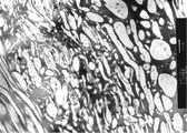
本発明の高分子電解質膜について透過型電子顕微鏡(TEM)による写真を図2に示す。図2は後述する実施例の例1で得られた膜の断面のTEM写真である。図2中、丸い形状や短いひも状になった部分が上述の分散相であり、分散相間の連続している部分が上述の連続相である。 A photograph taken with a transmission electron microscope (TEM) of the polymer electrolyte membrane of the present invention is shown in FIG. FIG. 2 is a TEM photograph of a cross section of the film obtained in Example 1 of an example described later. In FIG. 2, a round shape or a short string portion is the above-described dispersed phase, and a continuous portion between the dispersed phases is the above-described continuous phase.
本発明では、イオン伝導性ポリマーに非相溶かつ溶融成形可能なポリマーとして、化学的安定性、機械的強度、溶融成型性等の観点から、含フッ素ポリマーを使用する。具体的には、テトラフルオロエチレン−ヘキサフルオロプロピレン共重合体(FEP)、テトラフルオロエチレン−エチレン共重合体(ETFE)、ポリビニリデンフルオライド(PVdF)、テトラフルオロエチレン−パーフルオロ(アルキルビニルエーテル)重合体、ポリクロロトリフルオロエチレン、エチレン−クロロトリフルオロエチレン共重合体、及びポリビニルフルオライドからなる群から選ばれる1種以上が好ましい。なかでも、溶融成形性の観点からFEPが特に好ましく用いられる。 In the present invention, a fluorine-containing polymer is used from the viewpoints of chemical stability, mechanical strength, melt moldability and the like as a polymer that is incompatible with the ion-conductive polymer and can be melt-molded. Specifically, tetrafluoroethylene-hexafluoropropylene copolymer (FEP), tetrafluoroethylene-ethylene copolymer (ETFE), polyvinylidene fluoride (PVdF), tetrafluoroethylene-perfluoro (alkyl vinyl ether) heavy One or more selected from the group consisting of a coalescence, polychlorotrifluoroethylene, ethylene-chlorotrifluoroethylene copolymer, and polyvinyl fluoride is preferred. Among these, FEP is particularly preferably used from the viewpoint of melt moldability.
これらのポリマーは、分子量が20000〜90000であることが好ましく、さらには25000〜65000であることが好ましい。分子量が低すぎると強度が低下する傾向にあり、分子量が高すぎるとフィルム成形性が悪くなる傾向にある。 These polymers preferably have a molecular weight of 20000 to 90000, more preferably 25000 to 65000. If the molecular weight is too low, the strength tends to decrease, and if the molecular weight is too high, the film formability tends to deteriorate.
また、イオン伝導性ポリマーとしては、従来より公知の重合体が広く採用される。なかでもスルホン酸基又はスルホンイミド基を有する含フッ素重合体が好ましく、特に耐久性の観点からスルホン酸基を有するパーフルオロカーボン重合体(エーテル結合性の酸素原子等を含んでもよい)が好ましい。スルホン酸基又はスルホンイミド基を有するイオン伝導性ポリマーは、−SO2F基又は−SO2Cl基を有する含フッ素重合体を置換して得られる。スルホン酸基を有するパーフルオロカーボン重合体の場合は、−SO2F基を有するパーフルオロカーボン重合体を加水分解及び酸型化して得ることが好ましい。 Moreover, conventionally well-known polymer is employ | adopted widely as an ion conductive polymer. Of these, a fluorinated polymer having a sulfonic acid group or a sulfonimide group is preferable, and a perfluorocarbon polymer having a sulfonic acid group (which may contain an etheric oxygen atom or the like) is particularly preferable from the viewpoint of durability. The ion conductive polymer having a sulfonic acid group or a sulfonimide group can be obtained by substituting a fluoropolymer having a —SO 2 F group or a —SO 2 Cl group. In the case of a perfluorocarbon polymer having a sulfonic acid group, it is preferable to obtain the perfluorocarbon polymer having a —SO 2 F group by hydrolysis and acidification.
−SO2F基を有するパーフルオロカーボン重合体である、上記前駆体としては、CF2=CF−(OCF2CFX)m−Op−(CF2)n−SO2Fで表されるフルオロビニル化合物(式中、Xはフッ素原子又はトリフルオロメチル基であり、mは0〜3の整数、nは0〜12の整数、pは0又は1であり、n=0のときはp=0かつmは1〜3である。)に基づく重合単位と、テトラフルオロエチレン、ヘキサフルオロプロピレンのようなパーフルオロオレフィン、クロロトリフルオロエチレン、又はパーフルオロ(アルキルビニルエーテル)に基づく重合単位とを含む共重合体が好ましい。特に上記フルオロビニル化合物に基づく重合単位とテトラフルオロエチレンに基づく重合単位とを含む共重合体が好ましい。 As the precursor, which is a perfluorocarbon polymer having a —SO 2 F group, a fluorovinyl represented by CF 2 ═CF— (OCF 2 CFX) m —O p — (CF 2 ) n —SO 2 F Compound (wherein X is a fluorine atom or a trifluoromethyl group, m is an integer of 0 to 3, n is an integer of 0 to 12, p is 0 or 1, and p = 0 when n = 0) And m is 1 to 3.) and a polymer unit based on a perfluoroolefin such as tetrafluoroethylene, hexafluoropropylene, chlorotrifluoroethylene, or perfluoro (alkyl vinyl ether). Polymers are preferred. In particular, a copolymer containing a polymer unit based on the fluorovinyl compound and a polymer unit based on tetrafluoroethylene is preferred.
上記フルオロビニル化合物の好ましい例としては、以下のいずれかの式で表される化合物が挙げられる。ただし、下記式中、qは1〜8の整数、rは1〜8の整数、sは1〜8の整数、tは1〜5の整数を示す。 Preferable examples of the fluorovinyl compound include compounds represented by any of the following formulas. However, in the following formula, q is an integer of 1 to 8, r is an integer of 1 to 8, s is an integer of 1 to 8, and t is an integer of 1 to 5.
本発明におけるイオン伝導性ポリマーのイオン交換容量としては、0.4〜1.5ミリ当量/g乾燥樹脂、特に0.9〜1.3ミリ当量/g乾燥樹脂であることが好ましい。イオン交換容量が低すぎると膜の抵抗が大きくなる傾向にあり、高すぎると膜の機械的強度が弱くなる傾向にある。 The ion exchange capacity of the ion conductive polymer in the present invention is preferably 0.4 to 1.5 meq / g dry resin, particularly 0.9 to 1.3 meq / g dry resin. If the ion exchange capacity is too low, the resistance of the membrane tends to increase, and if it is too high, the mechanical strength of the membrane tends to become weak.
また、高分子電解質膜において、イオン伝導性ポリマーと溶融成形可能なポリマーとの含有比は、電導性とメタノール透過性の観点から質量比で30/70〜70/30、特には40/60〜60/40が好ましい。溶融成形可能なポリマーが多すぎると抵抗が高くなり、少なすぎるとメタノールの透過が充分には抑制されないおそれがある。
また、本発明の高分子電解質膜の厚さは、強度、取り扱い性及び膜抵抗の観点から、5〜200μm、特には20〜100μmであるのが好ましい。膜厚が薄すぎると機械的な強度が弱くなる傾向にある。膜厚が厚すぎると膜の抵抗が高くなる傾向にある。
In the polymer electrolyte membrane, the content ratio of the ion conductive polymer to the melt-moldable polymer is 30/70 to 70/30, particularly 40/60 to mass ratio in terms of conductivity and methanol permeability. 60/40 is preferred. If there is too much polymer that can be melt-molded, the resistance will be high, and if it is too low, the permeation of methanol may not be sufficiently suppressed.
The thickness of the polymer electrolyte membrane of the present invention is preferably 5 to 200 μm, particularly 20 to 100 μm from the viewpoints of strength, handleability and membrane resistance. If the film thickness is too thin, the mechanical strength tends to be weakened. If the film thickness is too thick, the resistance of the film tends to increase.
次に、本発明の高分子電解質膜の好ましい製造方法について詳細に説明する。本発明における電解質膜は、−SO2X基を有するポリマー(Xはフッ素原子又は塩素原子)と、該ポリマーと非相溶でありかつ溶融成形可能な含フッ素ポリマーとを混合する工程、前記含フッ素ポリマーが溶融する温度で混練する工程、フィルム化する工程及び−SO2X基をスルホン酸基又はスルホンイミド基に変換する工程を経て得られる。 Next, the preferable manufacturing method of the polymer electrolyte membrane of this invention is demonstrated in detail. The electrolyte membrane in the present invention comprises a step of mixing a polymer having —SO 2 X groups (X is a fluorine atom or a chlorine atom) and a fluorine-containing polymer that is incompatible with the polymer and can be melt-molded. It is obtained through a step of kneading at a temperature at which the fluoropolymer melts, a step of forming a film, and a step of converting —SO 2 X groups into sulfonic acid groups or sulfonimide groups.
高分子電解質膜に含まれるイオン伝導性ポリマーとしてスルホン酸基を有するパーフルオロカーボン重合体を用いる場合を例にとって、具体的な好ましい手順を説明すると、以下のとおりである。
(1)溶融成形可能な含フッ素ポリマーと−SO2F基を有するパーフルオロカーボン重合体との混合。
(2)(1)で得られた混合物の、上記含フッ素ポリマーが溶融する温度での混練、ペレット化。
(3)(2)で得られたペレットを用いて押出し成形によるフィルム化。
(4)(3)で得られたフィルム2枚を、互いのMD方向が直行するように重ねて積層。
(5)加水分解、酸型化処理、洗浄、乾燥。
A specific preferred procedure will be described as follows, taking as an example the case of using a perfluorocarbon polymer having a sulfonic acid group as the ion conductive polymer contained in the polymer electrolyte membrane.
(1) Mixing of a melt-formable fluorine-containing polymer and a perfluorocarbon polymer having a —SO 2 F group.
(2) Kneading and pelletizing the mixture obtained in (1) at a temperature at which the fluoropolymer melts.
(3) Film formation by extrusion molding using the pellet obtained in (2).
(4) The two films obtained in (3) are overlapped and laminated so that their MD directions are orthogonal.
(5) Hydrolysis, acidification treatment, washing and drying.
上記(1)〜(5)の工程をさらに具体的に説明する。
まず、溶融成形可能な含フッ素ポリマーと−SO2F基を有するパーフルオロカーボン重合体とを充分に混合する((1)の工程)。この混合には例えばVブレンダー、リボンミキサー、ヘンシェルミキサー等の混合機等が使用される。次に、得られた混合物を、溶融成形可能な含フッ素ポリマーが溶融する温度で混練する((2)の工程)。この際、例えば2軸押出し機、コ・ニーダ、非スクリュー型押出し機(インスタ・メルト)等により混練、ペレット化することができる。
The steps (1) to (5) will be described more specifically.
First, a melt-formable fluorine-containing polymer and a perfluorocarbon polymer having —SO 2 F groups are sufficiently mixed (step (1)). For this mixing, for example, a blender such as a V blender, a ribbon mixer, a Henschel mixer or the like is used. Next, the obtained mixture is kneaded at a temperature at which the melt-formable fluoropolymer melts (step (2)). At this time, for example, it can be kneaded and pelletized by a twin screw extruder, a co-kneader, a non-screw type extruder (insta-melt) or the like.
次いで得られたペレットは、(3)の工程で、好ましくは加熱下で単軸押出し成形されフィルム化される。また、(2)のペレット化する工程を経ずに、上記混合物を直接押出し成形し、この押出し成形の工程でフィルム化してもよい。加熱下で単軸押出し成形する場合は、成形(ダイス)温度が260〜310℃程度となるように成形することが好ましい。成形温度が260℃未満の場合は、フィルムの表面が荒れて厚さが不均一になり、また溶融伸度も低下し薄膜成形性が悪くなるおそれがあり好ましくない。また、成形(ダイス)温度が320℃を超えるとイオン伝導性ポリマーの熱分解が起こるおそれがあり好ましくない。このようにして(3)の工程を終えて得られるフィルムの厚さは5〜200μm程度となる。 Next, the obtained pellets are formed into a film by uniaxial extrusion molding in the step (3), preferably under heating. Alternatively, the mixture may be directly extruded and formed into a film in this extrusion step without going through the pelletizing step of (2). In the case of uniaxial extrusion molding under heating, it is preferable to mold so that the molding (die) temperature is about 260 to 310 ° C. When the molding temperature is less than 260 ° C., the surface of the film becomes rough and the thickness becomes non-uniform, and the melt elongation is lowered and the thin film moldability may be deteriorated. Further, if the molding (die) temperature exceeds 320 ° C., the ion conductive polymer may be thermally decomposed, which is not preferable. Thus, the thickness of the film obtained by finishing the step (3) is about 5 to 200 μm.
膜の面内強度を均一化させたい場合は、次いで(4)の工程を行う。すなわち、2枚のフィルムを、互いのMD方向が直行するように重ねて積層する。積層は、金属又はゴムロールが対になった熱ロールプレス、平板熱プレス等により行うことができる。
次に、パーフルオロカーボン重合体の−SO2F基をスルホン酸基(−SO3H基)に変換するため、加水分解、酸型化処理、洗浄、乾燥を行う((5)の工程)。
When it is desired to make the in-plane strength of the film uniform, the step (4) is then performed. That is, two films are stacked so that their MD directions are perpendicular to each other. Lamination can be performed by a hot roll press in which a metal or rubber roll is paired, a flat plate hot press or the like.
Next, in order to convert the —SO 2 F group of the perfluorocarbon polymer into a sulfonic acid group (—SO 3 H group), hydrolysis, acidification treatment, washing, and drying are performed (step (5)).
なお、スルホンイミド基を有するイオン導電性ポリマーにより電解質膜を構成する場合は、(5)の工程のかわりに−SO2F基をスルホンイミド基に変換する工程を行う。この工程には公知の方法を用いることができる。例えば、トリフルオロメタンスルホンアミド、ヘプタフルオロエタンスルホンアミド、ノナフルオロブタンスルホンアミド等のパーフルオロスルホンアミドをアルカリ金属フッ化物や有機アミン等の塩基性化合物存在下に接触させる方法や、該スルホンアミドのアルカリ金属、アルカリ土類金属塩、該金属塩をさらにシリル化した化合物と接触させる方法により、ポリマー中の−SO2F基を反応させ、塩基由来の塩型のスルホンイミド基に変換した後、さらに塩酸や硫酸等の水溶液で酸型化することでスルホンイミド基に変換できる。ここで上記化合物と膜中の−SO2F基を接触させる方法としては、上記化合物が可溶な溶媒に溶解した溶液を膜と必要により加熱しながら接触させることが好ましい。
In the case of the membrane by ion-conductive polymer having a sulfonimide group, a step of converting the sulfonimide groups -SO 2 F groups in place of step (5). A known method can be used for this step. For example, a method of contacting perfluorosulfonamide such as trifluoromethanesulfonamide, heptafluoroethanesulfonamide, and nonafluorobutanesulfonamide in the presence of a basic compound such as an alkali metal fluoride or organic amine, metal, alkaline earth metal salts, the method of contacting with a compound obtained by further silylation the metal salt, by reacting -
上記溶媒としては、メタノール、エタノール、ペンタフルオロプロパノール、テトラフルオロプロパノール等のアルコール類、アセトン、メチルエチルケトン等のケトン系溶剤、テトラヒドロフラン、グライム、ジオキサン等のエーテル系溶剤、アセトニトリル、N,N−ジメチルホルムアミド、N,N−ジメチルアセトアミド、N−メチル−2−ピロリジノン、ジメチルスルホキシド等が挙げられるが、これらに限られない。また、これらの溶媒と含フッ素溶媒との混合溶媒も、膜と溶液との接触時の濡れ性、膜の膨潤等の効果により反応をより効率的に進行させることができる場合があり、好ましい。 Examples of the solvent include alcohols such as methanol, ethanol, pentafluoropropanol and tetrafluoropropanol, ketone solvents such as acetone and methyl ethyl ketone, ether solvents such as tetrahydrofuran, glyme and dioxane, acetonitrile, N, N-dimethylformamide, Examples include, but are not limited to, N, N-dimethylacetamide, N-methyl-2-pyrrolidinone, dimethyl sulfoxide and the like. In addition, a mixed solvent of these solvents and a fluorine-containing solvent is also preferable because the reaction can be more efficiently proceeded due to effects such as wettability at the time of contact between the film and the solution and swelling of the film.
上記のように作製することで最終的にスルホン酸基又はスルホンイミド基を有するイオン伝導性ポリマー部と溶融成形可能なポリマー部が緻密な相分離構造をとる電解質膜とすることができる。さらに、イオン伝導性ポリマーの溶融粘度ηm、含有比φm、溶融成形可能なポリマーの溶融粘度ηd、含有比φdとした時、(ηm/ηd)×(φd/φm)の値が1に近くなるようにすることが好ましい。この値を1に近づけることで、より緻密な、アスペクト比の大きな分散相を形成する相分離構造とすることができる。 By producing as described above, an ion membrane having a sulfonic acid group or a sulfonimide group and an electrolyte membrane having a dense phase separation structure can be obtained. Further, when the melt viscosity η m of the ion conductive polymer, the content ratio φ m , the melt viscosity η d of the melt moldable polymer, and the content ratio φ d are (η m / η d ) × (φ d / φ m ) Is preferably close to 1. By bringing this value close to 1, a finer phase separation structure that forms a dispersed phase having a large aspect ratio can be obtained.
この電解質膜において、メタノール透過性が抑制される要因は明らかではないが、緻密な相分離構造をとることによって、分散相が、スルホン酸基によるクラスターネットワーク部が水又はメタノールによって膨潤することを抑制する機能を発揮することが考えられる。また、分散相はメタノール不透過性なので、膜内を通過するメタノールの実質的な拡散距離が長くなること等も考えられる。 In this electrolyte membrane, the factor that suppresses methanol permeability is not clear, but by taking a dense phase separation structure, the dispersed phase suppresses the swelling of the cluster network part due to sulfonic acid groups with water or methanol. It is considered that the function to perform is performed. In addition, since the dispersed phase is impermeable to methanol, the substantial diffusion distance of methanol passing through the membrane may be increased.
本発明の電解質膜は、メタノール透過性が抑制されているので、DMFC用の電解質膜として使用すると、出力の高いDMFCが得られる。また、本発明の好ましい態様として(4)の工程等を行うことにより、水やメタノールに浸漬しても寸法変化が少ない強度の高い電解質膜が得られるため、この電解質膜を用いるとDMFCを長期間運転しても安定して高い出力を得ることが可能となる。また、このような電解質膜は水に対する寸法変化率も低いので、水素/酸素型の固体高分子電解質膜としても有用である。 Since the electrolyte membrane of the present invention has suppressed methanol permeability, a DMFC with high output can be obtained when used as an electrolyte membrane for DMFC. Further, as a preferred embodiment of the present invention, by performing the step (4) and the like, an electrolyte membrane having a high strength with little dimensional change even when immersed in water or methanol can be obtained. It is possible to stably obtain a high output even during operation for a period. In addition, since such an electrolyte membrane has a low dimensional change rate with respect to water, it is also useful as a hydrogen / oxygen type solid polymer electrolyte membrane.
以下、本発明について、実施例及び比較例により具体的に説明するが、本発明はこれらに限定されない。 EXAMPLES Hereinafter, although an Example and a comparative example demonstrate this invention concretely, this invention is not limited to these.
[例1(実施例)]
テトラフルオロエチレンに基づく重合単位とCF2=CF−OCF2CF(CF3)O(CF2)2SO2Fに基づく重合単位とからなる共重合体粉末(酸型化したときのイオン交換容量1.1ミリ当量/g乾燥樹脂、以下、共重合体Aという。)とFEP(372℃におけるメルトインデックス7)とを質量比で50:50(容量比で52:48)になるようにして粉体混合機により十分混合した。この混合物を二軸押出し機(池貝社製、PCM30)を用い、300℃で混練した後、直径2.5mmのストランドを押出し、これを長さ2.5mmに切断してペレットを得た。このペレットを口径30mmの単軸押出し機(田辺プラスチックス社製、VS30)に供給し、350mmの口金幅を有するフラットダイを用い、ダイス温度300℃、押出し量1.3kg/hにて押出した。
[Example 1 (Example)]
Tetrafluoroethylene based polymer unit and CF 2 = CF-OCF 2 CF (CF 3) O (CF 2) 2
得られた押出し物を表面温度が30〜50℃になるように調整したロールにより1.71m/分の速度で引き取ることにより、共重合体AとFEPとからなる厚さ20μmのブレンドフィルムを得た。次に、金属ロールと厚さ10mmのゴムを被覆したロールとの一対からなるロールを、金属ロール温度200℃、ゴム被覆ロール温度135℃に調整した。上記ブレンドフィルム2枚を、それらの押し出し方向(以下、MD方向という)どうしが直行するように重ね、フィルム幅で換算した線圧力が40kg/cmとなるように加圧して上記ロール間を押し出し速度0.4m/分で通すことにより、40μmの積層ブレンドフィルムを得た。 The obtained extrudate is taken up at a speed of 1.71 m / min with a roll adjusted so that the surface temperature is 30 to 50 ° C., thereby obtaining a blend film having a thickness of 20 μm composed of copolymer A and FEP. It was. Next, a roll consisting of a pair of a metal roll and a roll coated with rubber having a thickness of 10 mm was adjusted to a metal roll temperature of 200 ° C. and a rubber-covered roll temperature of 135 ° C. Two blend films are stacked so that their extruding directions (hereinafter referred to as MD directions) are perpendicular to each other, and the linear pressure in terms of film width is increased to 40 kg / cm to extrude between the rolls. By passing it at 0.4 m / min, a laminated blend film of 40 μm was obtained.
次いで、この積層ブレンドフィルムをジメチルスルホキシド(以下、DMSOという)、水酸化カリウム(KOH)を質量比で30:15の割合で含む水溶液を用い、温度95℃、浸漬時間30分で加水分解した後、イオン交換水にて十分に洗浄した。次に、1モル/Lの硫酸にて、温度25℃、浸漬時間60分で酸型化処理して−SO3H基に変換した後、脱イオン水で十分洗浄した。次いで、表面の水分をろ紙で除去した後、温度25℃、相対湿度50%の条件で予備乾燥を行い、さらに65℃のオーブン中で60分間加熱乾燥し、電解質膜を得た。 Next, this laminated blend film was hydrolyzed using an aqueous solution containing dimethyl sulfoxide (hereinafter referred to as DMSO) and potassium hydroxide (KOH) in a mass ratio of 30:15 at a temperature of 95 ° C. and an immersion time of 30 minutes. And thoroughly washed with ion-exchanged water. Next, it was acidified with 1 mol / L sulfuric acid at a temperature of 25 ° C. and an immersion time of 60 minutes to convert it into —SO 3 H groups, and then thoroughly washed with deionized water. Next, after removing moisture on the surface with filter paper, preliminary drying was performed under conditions of a temperature of 25 ° C. and a relative humidity of 50%, and further heat-dried in an oven at 65 ° C. for 60 minutes to obtain an electrolyte membrane.
[例2(実施例)]
共重合体AとFEPの組成比を質量比で60:40(容量比で62:38)になるようにした以外は、例1と同様にしてフィルム化し、厚さ20μmのブレンドフィルムを得た。このブレンドフィルム2枚を例1と同様に直交積層、加水分解、酸型化、乾燥して厚さ40μmの電解質膜を得た。
[Example 2 (Example)]
A blend film having a thickness of 20 μm was obtained in the same manner as in Example 1 except that the composition ratio of copolymer A and FEP was 60:40 by mass ratio (62:38 by volume ratio). . Two blend films were orthogonally laminated, hydrolyzed, acidified and dried in the same manner as in Example 1 to obtain an electrolyte membrane having a thickness of 40 μm.
[例3(実施例)]
共重合体AとETFE(旭硝子社製、製品名:フルオンLM−730AP。メルトインデックス35)を質量比で55:45(容量比で52:48)になるように混合して原料として使用した以外は、例1と同様にしてフィルム化し、厚さ20μmのブレンドフィルムを得た。このブレンドフィルム2枚を例1と同様に直交積層、加水分解、酸型化、乾燥して厚さ40μmの電解質膜を得た。
[Example 3 (Example)]
Copolymer A and ETFE (manufactured by Asahi Glass Co., Ltd., product name: Fullon LM-730AP, melt index 35) were mixed to a mass ratio of 55:45 (volume ratio 52:48) and used as a raw material. Was made into a film in the same manner as in Example 1 to obtain a blend film having a thickness of 20 μm. Two blend films were orthogonally laminated, hydrolyzed, acidified and dried in the same manner as in Example 1 to obtain an electrolyte membrane having a thickness of 40 μm.
[例4(実施例)]
共重合体AとFEPの組成比を質量比で50:50(容量比で52:48)になるようにし、例1と同様にしてフィルム化し、厚さ60μmの膜を得た。次いで、フィルムのMD方向のみに温度95℃、速度2m/分で、延伸倍率3倍の延伸を行い、厚さ20μmのブレンドフィルムを得た。このブレンドフィルム2枚を例1と同様に直交積層、加水分解、酸型化、乾燥して厚さ40μmの電解質膜を得た。
[Example 4 (Example)]
The composition ratio of copolymer A and FEP was adjusted to 50:50 by mass (52:48 by volume), and a film was formed in the same manner as in Example 1 to obtain a film having a thickness of 60 μm. Subsequently, the film was stretched 3 times in the MD direction at a temperature of 95 ° C. and a speed of 2 m / min to obtain a blend film having a thickness of 20 μm. Two blend films were orthogonally laminated, hydrolyzed, acidified and dried in the same manner as in Example 1 to obtain an electrolyte membrane having a thickness of 40 μm.
[例5(比較例)]
共重合体Aのみを用い、例1と同様にしてフィルム化し、厚さ20μmのフィルムを得た。このフィルム2枚を例1と同様に直交積層、加水分解、酸型化、乾燥して厚さ40μmの重合体Aのみからなる電解質膜を得た。
[Example 5 (comparative example)]
Using only copolymer A, a film was formed in the same manner as in Example 1 to obtain a film having a thickness of 20 μm. Two films were orthogonally laminated, hydrolyzed, acidified, and dried in the same manner as in Example 1 to obtain an electrolyte membrane consisting only of polymer A having a thickness of 40 μm.
[例6(実施例)]
共重合体AとFEPの組成比を質量比で50:50(容量比で52:48)になるようにし、例1と同様にしてフィルム化し、厚さ20μmのブレンドフィルムを得た。このブレンドフィルム2枚を膜のMD方向が一致するように積層した以外は、例1と同様に加水分解、酸型化、乾燥して厚さ40μmのポリマーブレンド電解質膜を得た。
[Example 6 (Example)]
The composition ratio of copolymer A and FEP was adjusted to 50:50 by mass (52:48 by volume), and a film was formed in the same manner as in Example 1 to obtain a blend film having a thickness of 20 μm. A polymer blend electrolyte membrane having a thickness of 40 μm was obtained by hydrolysis, acidification, and drying in the same manner as in Example 1 except that these two blend films were laminated so that the MD directions of the membranes coincided.
[例7(実施例)]
共重合体AをDMSO、水酸化カリウムを質量比で30:15の割合で含む水溶液で加水分解し、1モル/Lの塩酸に室温にて16時間浸漬して酸型化処理を行い、水洗、乾燥した。これを、エタノールに分散させ、固形分濃度が溶液全体の質量の10%の、スルホン酸基を含有するイオン交換体ポリマー分散液を得た。次いで、FEP(粉体)を1000メッシュのふるいで分級し、20μm以下の微粉末を得た。得られたイオン交換体ポリマー分散液と微粉末FEPを質量比が50:50(容量比が52:48)になるよう混合し、FEP微粉末含有イオン交換体ポリマー分散液を得た。これをPETフィルム上にバーコーターで塗工し、90℃のオーブン中で30分間加熱乾燥し、40μmの電解質膜を得た。
[Example 7 (Example)]
The copolymer A is hydrolyzed with an aqueous solution containing DMSO and potassium hydroxide in a mass ratio of 30:15, immersed in 1 mol / L hydrochloric acid for 16 hours at room temperature, acidified, and washed with water. , Dried. This was dispersed in ethanol to obtain an ion exchanger polymer dispersion containing a sulfonic acid group having a solid concentration of 10% of the mass of the whole solution. Next, FEP (powder) was classified with a 1000 mesh sieve to obtain a fine powder of 20 μm or less. The obtained ion exchanger polymer dispersion and fine powder FEP were mixed so that the mass ratio was 50:50 (volume ratio was 52:48) to obtain an ion exchanger polymer dispersion containing FEP fine powder. This was coated on a PET film with a bar coater and heat-dried in a 90 ° C. oven for 30 minutes to obtain a 40 μm electrolyte membrane.
例1〜7の各例で得られた膜について、下記の諸特性を測定した。その結果を表1に示す。 The following characteristics were measured for the films obtained in Examples 1 to 7. The results are shown in Table 1.
[引張弾性率]
引張弾性率はJIS K7127に準じて測定した。まず、各例で得られたそれぞれの電解質膜について、幅1cm、長さ15cmの短冊状サンプルを切り出した。このサンプルは、長さ方向が電解質膜のMD方向と一致するサンプルと、長さ方向がMD方向と直交するサンプルの2種類についてそれぞれ作製した。なお、MD方向が直行するように2枚のフィルムを積層した積層膜の場合は、積層膜を構成するフィルムの一方のフィルムのMD方向を長さ方向としたサンプルについての測定値をX1、もう一方のフィルムのMD方向を長さ方向としたサンプルについての測定値をY1とした。測定は、標点間距離50mm、チャック間距離100mm、試験速度50mm/分で引張って行い、得られた変位(歪)と応力より、初期の4%歪における引張弾性率を求めた。測定は、25℃、相対湿度50%の条件において、5サンプルについて行い、その平均値を求めた。
[Tensile modulus]
The tensile modulus was measured according to JIS K7127. First, for each electrolyte membrane obtained in each example, a strip sample having a width of 1 cm and a length of 15 cm was cut out. This sample was produced for each of two types: a sample whose length direction matches the MD direction of the electrolyte membrane, and a sample whose length direction is orthogonal to the MD direction. In addition, in the case of a laminated film in which two films are laminated so that the MD direction is perpendicular, the measured value for a sample in which the MD direction of one of the films constituting the laminated film is the length direction is X 1 , the measurements for samples with a length direction of the MD direction of the other film was Y 1. The measurement was performed by pulling at a distance between gauge points of 50 mm, a distance between chucks of 100 mm, and a test speed of 50 mm / min, and the tensile modulus at an initial 4% strain was determined from the obtained displacement (strain) and stress. The measurement was performed on 5 samples under the conditions of 25 ° C. and relative humidity of 50%, and the average value was obtained.
[引裂き強さ]
引裂き強さはJIS K7128に準じて測定した。まず、各例で得られたそれぞれの電解質膜について、幅5cm、長さ15cmの短冊状サンプルを切り出した。このサンプルは、引張弾性率の測定サンプルと同様に、長さ方向がフィルムのMD方向と一致するサンプルと、MD方向と直交する方向と一致するサンプルの2種類をそれぞれ作製し、積層膜の場合も引張弾性率の測定サンプルと同様にした。すなわち前者の測定値をX2、後者の測定値をY2とした。各サンプルは、長さ方向に沿って2等分するように、短辺の中央から長さ15cmの半分の7.5cmまで切れ目を入れる。次いで、切れ目部分から引裂かれるように、切れ端の一方を引張り試験機の上部チャックに、もう一方を下部チャックに取り付け、25℃、相対湿度50%の条件で200mm/分の速度でチャック間を広げ、引裂き荷重を測定する。引裂き強さは、引裂き荷重をサンプルの厚さで除した値(N/mm)として算出する。各方向について5サンプルずつ測定し、その平均値を引裂き強さとする。
なお、例6ではY2の引裂き強さの測定中に、引裂き方向がX方向に移ってしまい、Y方向についての引裂き強さの評価ができなかった。
[Tear strength]
The tear strength was measured according to JIS K7128. First, for each electrolyte membrane obtained in each example, a strip sample having a width of 5 cm and a length of 15 cm was cut out. In the case of a laminated film, this sample was prepared in the same manner as the sample for measuring the tensile modulus of elasticity, in which a sample whose length direction matches the MD direction of the film and a sample whose length direction matches the direction orthogonal to the MD direction The tensile modulus of elasticity was the same as the measurement sample. That is, the former measured value was X 2 and the latter measured value was Y 2 . Each sample is cut from the center of the short side to 7.5 cm, which is half of the length of 15 cm, so as to be divided into two equal parts along the length direction. Next, one of the cut ends is attached to the upper chuck of the tensile tester and the other end is attached to the lower chuck so as to be torn from the cut portion, and the gap between the chucks is widened at a speed of 200 mm / min at 25 ° C. and 50% relative humidity. Measure the tear load. The tear strength is calculated as a value (N / mm) obtained by dividing the tear load by the thickness of the sample. Five samples are measured for each direction, and the average value is taken as the tear strength.
Incidentally, during the measurement of the tear strength of Example 6, Y 2, tear direction will move to the X-direction, it can not evaluate the tear strength in the Y direction.
[寸法変化率]
寸法変化率は、以下のようにして測定した。まず、各例で得られたそれぞれの電解質膜について、一辺がMD方向と平行になるように、5cm角の正方形サンプルを切り出した。このサンプルを25℃、相対湿度50%の環境で4時間保持した後、その環境中でMD方向と平行な一辺の長さx1(cm)と、その辺と直交する一辺の長さy1(cm)とを測定した。次いで、サンプルを90℃の脱イオン水に16時間浸漬した後、水中下で同様にMD方向と平行な一辺の長さx2(cm)と、その辺と直交する一辺の長さy2(cm)とを測定した。寸法変化率は、以下のように算出した。
MD方向の寸法変化率X3(%):(x2−x1)/x1×100
MD方向と垂直な方向の寸法変化率Y3(%):(y2−y1)/y1×100
[Dimensional change rate]
The dimensional change rate was measured as follows. First, for each electrolyte membrane obtained in each example, a square sample of 5 cm square was cut out so that one side was parallel to the MD direction. After holding this sample in an environment of 25 ° C. and a relative humidity of 50% for 4 hours, the length x 1 (cm) of one side parallel to the MD direction and the length y 1 of one side perpendicular to the side in the environment. (Cm) was measured. Next, after immersing the sample in deionized water at 90 ° C. for 16 hours, the length x 2 (cm) of one side parallel to the MD direction and the length y 2 (one side orthogonal to the side) in the same manner in water. cm). The dimensional change rate was calculated as follows.
Dimensional change rate in MD direction X 3 (%): (x 2 −x 1 ) / x 1 × 100
Dimensional change rate Y 3 (%) in the direction perpendicular to the MD direction: (y 2 −y 1 ) / y 1 × 100
[ポリマーブレンド電解質膜断面のTEM観察]
膜の断面についてTEMを用いて相分離構造を観察した。拡大倍率10000倍にて観察し、相分離の有無を確認した。例1についてのTEM写真を図2に示す。
[TEM observation of cross section of polymer blend electrolyte membrane]
The phase separation structure was observed using TEM for the cross section of the membrane. Observation at an enlargement magnification of 10,000 times confirmed the presence or absence of phase separation. A TEM photograph of Example 1 is shown in FIG.
[例8(実施例)]
例1で得られた厚さ20μmのブレンドフィルムに対し、積層せずに例1で得られた積層ブレンドフィルムと同様に加水分解、酸型化、洗浄、乾燥の処理を行い、厚さ20μmの電解質膜を得た。
[Example 8 (Example)]
The 20 μm thick blend film obtained in Example 1 was hydrolyzed, acidified, washed and dried in the same manner as the laminated blend film obtained in Example 1 without being laminated. An electrolyte membrane was obtained.
[例9(実施例)]
重合体AとFEPの組成比を質量比で40:60(容量比で42:58)になるようにした以外は例1と同様にしてブレンドフィルムを得て、例8と同様に積層せずに加水分解、酸型化、洗浄、乾燥の処理を行い、厚さ20μmの電解質膜を得た。
[Example 9 (Example)]
A blend film was obtained in the same manner as in Example 1 except that the composition ratio of the polymer A and FEP was 40:60 by mass (42:58 by volume), and was not laminated as in Example 8. Then, hydrolysis, acidification, washing, and drying were performed to obtain an electrolyte membrane having a thickness of 20 μm.
[例10(実施例)]
FEPのかわりにETFEを用い、共重合体AとETFE(旭硝子社製、LM−730AP)を質量比で55:45(容量比で52:48)になるようにして、例1と同様にしてブレンドフィルムを得て、例8と同様に積層せずに加水分解、酸型化、洗浄、乾燥の処理を行い、厚さ20μmの電解質膜を得た。
[Example 10 (Example)]
ETFE was used instead of FEP, and copolymer A and ETFE (manufactured by Asahi Glass Co., Ltd., LM-730AP) were made to have a mass ratio of 55:45 (capacity ratio 52:48) in the same manner as in Example 1. A blend film was obtained, and hydrolysis, acidification, washing and drying were performed in the same manner as in Example 8 without laminating to obtain an electrolyte membrane having a thickness of 20 μm.
[例11(比較例)]
重合体Aのみを用い、例7と同様にしてフィルム化し、厚さ20μmのフィルムを得て、例8と同様に積層せずに加水分解、酸型化、洗浄、乾燥の処理を行い、厚さ20μmの電解質膜を得た。
[Example 11 (comparative example)]
Using only the polymer A, a film was formed in the same manner as in Example 7, to obtain a film having a thickness of 20 μm, and in the same manner as in Example 8, hydrolysis, acidification, washing and drying were performed without lamination. An electrolyte membrane having a thickness of 20 μm was obtained.
例8〜11で得られた膜について、以下のように測定を行い、メタノール透過係数と比抵抗を求めた。その結果を表2に示す。 About the film | membrane obtained in Examples 8-11, it measured as follows and calculated | required the methanol permeability coefficient and specific resistance. The results are shown in Table 2.
[メタノール透過係数]
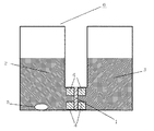
メタノール透過係数は、以下のようにして測定、算出した。まず、測定する膜を2cm角に切り出し、膜の厚さL1(cm)を測定した。次いで、この膜1を、図1に示すメタノール透過測定用セル6に挟みこみ、膜の片面の容器(水用)2には水、もう一方の面の容器(メタノール用)3には30%メタノール水溶液を同時に入れ、時間経過とともにメタノールが膜1を透過した量をガスクロマトグラフィーを用いて測定した。具体的には、ガスクロマトグラフィーにより、t(sec)経過した後の容器2内のメタノール濃度a(質量割合)を測定する。
[Methanol permeability coefficient]
The methanol permeability coefficient was measured and calculated as follows. First, the film to be measured was cut into a 2 cm square, and the thickness L 1 (cm) of the film was measured. Next, this membrane 1 is sandwiched between methanol
なお、膜1はガスケット4により固定し、容器2内には、膜を透過するメタノールを均一に分散させるために撹拌子5を入れて液を撹拌した。t(sec)経過したときのメタノール透過量V(cm3)を算出することにより、以下のとおりメタノール透過係数を算出した。ただし、ここでdはメタノールの密度(g/cm3)であり、S1(cm2)はメタノールが透過可能な膜の面積である。ここで、各例において、dは0.285g/cm3としてメタノール透過係数を求めた。
V=a×容器2内の液体の質量(g)/d
メタノール透過係数(cm2/sec)=V/t×L1/S1。
The membrane 1 was fixed with a gasket 4, and a stirring
V = a × mass of liquid in container 2 (g) / d
Methanol permeability coefficient (cm 2 / sec) = V / t × L 1 / S 1 .
[比抵抗(膜厚方向)]
比抵抗は、以下のようにして測定した。まず、膜を3cm×4cmの大きさに切り出し、温度80℃、0.1モル/Lの硫酸水溶液に1時間浸漬させる。次いで、硫酸水溶液を含浸させた膜の厚みL2(cm)を測定する。膜を抵抗測定用セルにセットした後、セル内を温度80℃の0.1モル/Lの硫酸水溶液で満たす。この状態(膜を挟んだ状態)で白金電極間の抵抗R1(Ω)を測定し、続いて膜をセットしていない状態での抵抗R0(Ω)を測定する。白金電極間の距離と膜の幅の積により通電面積S2(cm2)を求めると、下式により比抵抗R(Ω・cm)が求められる。なお、抵抗の測定は、交流インピーダンス法(10kHz)にて行った。
実行抵抗(Ω・cm2)=(R1−R0)×S2、
比抵抗R(Ω・cm)=実行抵抗/膜厚L2。
[Specific resistance (film thickness direction)]
The specific resistance was measured as follows. First, the membrane is cut into a size of 3 cm × 4 cm and immersed in an aqueous sulfuric acid solution at a temperature of 80 ° C. and 0.1 mol / L for 1 hour. Next, the thickness L 2 (cm) of the membrane impregnated with the sulfuric acid aqueous solution is measured. After setting the membrane in a resistance measurement cell, the cell is filled with a 0.1 mol / L sulfuric acid aqueous solution at a temperature of 80 ° C. In this state (a state where the film is sandwiched), the resistance R 1 (Ω) between the platinum electrodes is measured, and then the resistance R 0 (Ω) in a state where the film is not set is measured. When the current-carrying area S 2 (cm 2 ) is obtained from the product of the distance between the platinum electrodes and the film width, the specific resistance R (Ω · cm) is obtained from the following equation. The resistance was measured by the AC impedance method (10 kHz).
Execution resistance (Ω · cm 2 ) = (R 1 −R 0 ) × S 2 ,
Specific resistance R (Ω · cm) = execution resistance / film thickness L 2 .
本発明によれば、従来技術の電解質膜に比べ、メタノールの透過が大幅に低減された電解質膜が得られる。したがって、本発明の電解質膜を電解質として備えるDMFCは、高出力が得られる。 According to the present invention, an electrolyte membrane can be obtained in which the permeation of methanol is significantly reduced as compared with the electrolyte membrane of the prior art. Therefore, a DMFC having the electrolyte membrane of the present invention as an electrolyte can obtain a high output.
1:膜
2:容器(水用)
3:容器(メタノール用)
4:ガスケット
5:撹拌子
6:メタノール透過測定用セル
1: Membrane 2: Container (for water)
3: Container (for methanol)
4: Gasket 5: Stirrer 6: Cell for methanol permeation measurement
Claims (10)
The polymer electrolyte membrane according to any one of claims 6 to 9, which is used for a direct methanol fuel cell.
Priority Applications (1)
| Application Number | Priority Date | Filing Date | Title |
|---|---|---|---|
| JP2004355264A JP2006160902A (en) | 2004-12-08 | 2004-12-08 | Polyelectrolyte membrane and its manufacturing method |
Applications Claiming Priority (1)
| Application Number | Priority Date | Filing Date | Title |
|---|---|---|---|
| JP2004355264A JP2006160902A (en) | 2004-12-08 | 2004-12-08 | Polyelectrolyte membrane and its manufacturing method |
Publications (1)
| Publication Number | Publication Date |
|---|---|
| JP2006160902A true JP2006160902A (en) | 2006-06-22 |
Family
ID=36663286
Family Applications (1)
| Application Number | Title | Priority Date | Filing Date |
|---|---|---|---|
| JP2004355264A Withdrawn JP2006160902A (en) | 2004-12-08 | 2004-12-08 | Polyelectrolyte membrane and its manufacturing method |
Country Status (1)
| Country | Link |
|---|---|
| JP (1) | JP2006160902A (en) |
Cited By (6)
| Publication number | Priority date | Publication date | Assignee | Title |
|---|---|---|---|---|
| WO2008001923A1 (en) * | 2006-06-26 | 2008-01-03 | Toyota Jidosha Kabushiki Kaisha | Porous film for electrolyte film in fuel cell and process for producing the same |
| JP2011003358A (en) * | 2009-06-17 | 2011-01-06 | Toyota Motor Corp | Method of manufacturing porous membrane for fuel-cell electrolyte membrane |
| JP2013527572A (en) * | 2010-05-10 | 2013-06-27 | ユーティーシー パワー コーポレイション | Cross-stacked electrochemical cell membrane |
| JP2014067605A (en) * | 2012-09-26 | 2014-04-17 | Nitto Denko Corp | Polymer electrolytic film and fuel battery using the same |
| US9413019B2 (en) | 2011-08-18 | 2016-08-09 | Audi Ag | Fuel cell and membrane therefore |
| EP3021395A4 (en) * | 2013-07-09 | 2017-02-08 | JSR Corporation | Electrolyte membrane, membrane-electrode assembly, and solid polymer fuel cell |
Citations (2)
| Publication number | Priority date | Publication date | Assignee | Title |
|---|---|---|---|---|
| WO2004030132A1 (en) * | 2002-09-30 | 2004-04-08 | Asahi Glass Company, Limited | Electrolyte film, process for producing the same, and solid polymer type fuel cell |
| JP2004319442A (en) * | 2003-04-01 | 2004-11-11 | Toray Ind Inc | Polymeric solid electrolyte and its manufacturing method |
-
2004
- 2004-12-08 JP JP2004355264A patent/JP2006160902A/en not_active Withdrawn
Patent Citations (2)
| Publication number | Priority date | Publication date | Assignee | Title |
|---|---|---|---|---|
| WO2004030132A1 (en) * | 2002-09-30 | 2004-04-08 | Asahi Glass Company, Limited | Electrolyte film, process for producing the same, and solid polymer type fuel cell |
| JP2004319442A (en) * | 2003-04-01 | 2004-11-11 | Toray Ind Inc | Polymeric solid electrolyte and its manufacturing method |
Cited By (7)
| Publication number | Priority date | Publication date | Assignee | Title |
|---|---|---|---|---|
| WO2008001923A1 (en) * | 2006-06-26 | 2008-01-03 | Toyota Jidosha Kabushiki Kaisha | Porous film for electrolyte film in fuel cell and process for producing the same |
| JP2008004500A (en) * | 2006-06-26 | 2008-01-10 | Toyota Motor Corp | Porous membrane for fuel cell electrolyte membrane and its manufacturing method |
| JP2011003358A (en) * | 2009-06-17 | 2011-01-06 | Toyota Motor Corp | Method of manufacturing porous membrane for fuel-cell electrolyte membrane |
| JP2013527572A (en) * | 2010-05-10 | 2013-06-27 | ユーティーシー パワー コーポレイション | Cross-stacked electrochemical cell membrane |
| US9413019B2 (en) | 2011-08-18 | 2016-08-09 | Audi Ag | Fuel cell and membrane therefore |
| JP2014067605A (en) * | 2012-09-26 | 2014-04-17 | Nitto Denko Corp | Polymer electrolytic film and fuel battery using the same |
| EP3021395A4 (en) * | 2013-07-09 | 2017-02-08 | JSR Corporation | Electrolyte membrane, membrane-electrode assembly, and solid polymer fuel cell |
Similar Documents
| Publication | Publication Date | Title |
|---|---|---|
| KR102112648B1 (en) | Polymer electrolyte membrane | |
| KR102112645B1 (en) | Polymer electrolyte film | |
| US6692858B2 (en) | Electrolyte membrane for polymer electrolyte fuel cell and producing method thereof | |
| CN100560612C (en) | By directly fluoridizing crosslinked polymer dielectric film | |
| JP6034200B2 (en) | Redox flow secondary battery | |
| US8003732B2 (en) | Gradient reinforced proton exchange membrane | |
| WO2012046777A1 (en) | Fluorine-containing polymer electrolyte membrane | |
| JP5331122B2 (en) | Reinforcing electrolyte membrane for fuel cell, membrane-electrode assembly for fuel cell, and polymer electrolyte fuel cell including the same | |
| JP2002260705A (en) | Solid polymer electrolyte material, liquid composite, solid polymer fuel cell, fluorine-containing polymer and solid polymer electrolyte film consisting of fluorine-containing polymer | |
| JP6328355B1 (en) | Electrolyte membrane and method for producing the same | |
| WO2018061838A1 (en) | Polymer, solid polymer electrolyte membrane, and membrane electrode assembly | |
| JP5489945B2 (en) | Fluorine polymer electrolyte membrane | |
| CN101542795A (en) | Solid polymer electrolyte membrane for polymer electrolyte fuel cell and membrane electrode assembly | |
| JP2007095433A (en) | Electrolyte film for solid polymer fuel cells, and its manufacturing method | |
| JP5189394B2 (en) | Polymer electrolyte membrane | |
| JP2006160902A (en) | Polyelectrolyte membrane and its manufacturing method | |
| Kim et al. | 10.36-polymers in membrane electrode assemblies | |
| JP2006164777A (en) | Membrane-electrode conjugate for direct methanol fuel cell and its manufacturing method | |
| JP2014110232A (en) | Fluorine-based polymer electrolyte film | |
| JP2002343380A (en) | Electrolyte film for solid polymer fuel cell, and manufacturing method of the same |
Legal Events
| Date | Code | Title | Description |
|---|---|---|---|
| A621 | Written request for application examination |
Free format text: JAPANESE INTERMEDIATE CODE: A621 Effective date: 20071025 |
|
| A977 | Report on retrieval |
Free format text: JAPANESE INTERMEDIATE CODE: A971007 Effective date: 20100611 |
|
| A131 | Notification of reasons for refusal |
Free format text: JAPANESE INTERMEDIATE CODE: A131 Effective date: 20100622 |
|
| A761 | Written withdrawal of application |
Free format text: JAPANESE INTERMEDIATE CODE: A761 Effective date: 20100630 |