JP2006156376A - High-brightness discharge lamp ballast and method of operating high-brightness discharge lamp - Google Patents
High-brightness discharge lamp ballast and method of operating high-brightness discharge lamp Download PDFInfo
- Publication number
- JP2006156376A JP2006156376A JP2005332055A JP2005332055A JP2006156376A JP 2006156376 A JP2006156376 A JP 2006156376A JP 2005332055 A JP2005332055 A JP 2005332055A JP 2005332055 A JP2005332055 A JP 2005332055A JP 2006156376 A JP2006156376 A JP 2006156376A
- Authority
- JP
- Japan
- Prior art keywords
- lamp
- voltage
- intensity discharge
- auxiliary
- discharge lamp
- Prior art date
- Legal status (The legal status is an assumption and is not a legal conclusion. Google has not performed a legal analysis and makes no representation as to the accuracy of the status listed.)
- Pending
Links
Images


Classifications
-
- H—ELECTRICITY
- H05—ELECTRIC TECHNIQUES NOT OTHERWISE PROVIDED FOR
- H05B—ELECTRIC HEATING; ELECTRIC LIGHT SOURCES NOT OTHERWISE PROVIDED FOR; CIRCUIT ARRANGEMENTS FOR ELECTRIC LIGHT SOURCES, IN GENERAL
- H05B41/00—Circuit arrangements or apparatus for igniting or operating discharge lamps
- H05B41/14—Circuit arrangements
- H05B41/26—Circuit arrangements in which the lamp is fed by power derived from dc by means of a converter, e.g. by high-voltage dc
- H05B41/28—Circuit arrangements in which the lamp is fed by power derived from dc by means of a converter, e.g. by high-voltage dc using static converters
- H05B41/288—Circuit arrangements in which the lamp is fed by power derived from dc by means of a converter, e.g. by high-voltage dc using static converters with semiconductor devices and specially adapted for lamps without preheating electrodes, e.g. for high-intensity discharge lamps, high-pressure mercury or sodium lamps or low-pressure sodium lamps
- H05B41/292—Arrangements for protecting lamps or circuits against abnormal operating conditions
- H05B41/2928—Arrangements for protecting lamps or circuits against abnormal operating conditions for protecting the lamp against abnormal operating conditions
-
- H—ELECTRICITY
- H05—ELECTRIC TECHNIQUES NOT OTHERWISE PROVIDED FOR
- H05B—ELECTRIC HEATING; ELECTRIC LIGHT SOURCES NOT OTHERWISE PROVIDED FOR; CIRCUIT ARRANGEMENTS FOR ELECTRIC LIGHT SOURCES, IN GENERAL
- H05B41/00—Circuit arrangements or apparatus for igniting or operating discharge lamps
- H05B41/14—Circuit arrangements
- H05B41/26—Circuit arrangements in which the lamp is fed by power derived from dc by means of a converter, e.g. by high-voltage dc
- H05B41/28—Circuit arrangements in which the lamp is fed by power derived from dc by means of a converter, e.g. by high-voltage dc using static converters
- H05B41/288—Circuit arrangements in which the lamp is fed by power derived from dc by means of a converter, e.g. by high-voltage dc using static converters with semiconductor devices and specially adapted for lamps without preheating electrodes, e.g. for high-intensity discharge lamps, high-pressure mercury or sodium lamps or low-pressure sodium lamps
- H05B41/292—Arrangements for protecting lamps or circuits against abnormal operating conditions
Abstract
Description
本発明は、高輝度放電ランプ安定器及び高輝度放電ランプを動作するための方法に関連する。 The present invention relates to a high intensity discharge lamp ballast and a method for operating a high intensity discharge lamp.
高輝度放電ランプは、より高い光出力でより明るい点灯をもたらす光源であり、より安定な点灯を達成するために安定器と呼ばれる装置で作動される。主としてインダクタから成る磁気安定器、及びスイッチング制御を提供する電子回路を持つ電子安定器の2つの型の安定器があり、電子安定器は、エネルギー節約目的用に昨今、より普及している。 A high intensity discharge lamp is a light source that provides brighter lighting with higher light output and is operated with a device called a ballast to achieve more stable lighting. There are two types of ballasts, magnetic ballasts consisting primarily of inductors, and electronic ballasts with electronic circuitry that provides switching control, and electronic ballasts have become more popular today for energy saving purposes.
米国特許第6426597号は、ガス放電ランプを動作するための電子安定器を開示し、この電子安定器は、フル・ブリッジを形成するように互いに連結された4つのスイッチから成る回路構成を持つ。 U.S. Pat. No. 6,426,597 discloses an electronic ballast for operating a gas discharge lamp, which has a circuit configuration consisting of four switches connected together to form a full bridge.
また、米国特許6448720号は、タンク回路及びDC−ACインバータを持つ放電ランプ駆動回路を開示し、DC−ACインバータはブリッジ回路を持ち、その中には複数のMOSFETがフル・ブリッジ構成に配列される。 US Pat. No. 6,448,720 discloses a discharge lamp driving circuit having a tank circuit and a DC-AC inverter, and the DC-AC inverter has a bridge circuit, in which a plurality of MOSFETs are arranged in a full bridge configuration. The
ところで、駆動回路が高輝度放電ランプを動作し始めるとき、ランプ内側の温度及び圧力がまだ低いので、ランプは十分な光出力を発生しない。温度及び圧力がかなり高くなるときに、ランプはその安定動作を始めるが、この時点で、もし高輝度放電ランプがオフされれば、ランプを再始動するのに時間がかかる。例えば、温度及び圧力が再度より低くなるまで、数分又は数十分かかるかもしれない。従って、高輝度放電ランプが停電のためにオフに切り替えられるなら、例えば電力が直後に戻るときでさえ、ランプは数十分の間、十分な光出力でその動作を再始動しないかもしれない。 By the way, when the driving circuit starts to operate the high intensity discharge lamp, the temperature and pressure inside the lamp are still low, so the lamp does not generate sufficient light output. When the temperature and pressure rise considerably, the lamp starts its stable operation, but at this point it takes time to restart the lamp if the high intensity discharge lamp is turned off. For example, it may take several minutes or tens of minutes until the temperature and pressure are again lower. Thus, if a high intensity discharge lamp is switched off due to a power failure, the lamp may not restart its operation with sufficient light output for a few tens of minutes, for example, even when power returns immediately thereafter.
米国特許第6489729号は、高輝度放電ランプがオフされる間、補助ランプをオンする補助点灯装置を開示する。補助点灯装置には、HIDランプ状態回路、位相制御回路、トライアック、補助光源、整流回路及び増幅器を具備される。HIDランプ状態回路は、高輝度放電ランプが「OFF」であることを示す信号を受信したとき、信号を位相制御回路に送って補助光源をオンする。整流回路及び増幅器は、フィードバック回路を形成し、整流回路は、補助光源に印加される電圧の振幅を持つ電圧信号を出力する。増幅器は、電圧信号を基準電圧と比較し、電圧信号と基準電圧との間の差を表すエラー信号を位相制御回路に出力する。エラー信号に基づいて、位相制御回路は、目標電圧が補助光源に印加されるようにトライアックを制御する。しかし、この補助点灯装置は、補助光源の電圧の検出の次にその検出された電圧に基づくフィードバック制御を必要とするから、補助点灯装置の性能が全く能率的でないかもしれないし、その回路構造はより複雑でコストの高い傾向がある。 US Pat. No. 6,489,729 discloses an auxiliary lighting device that turns on the auxiliary lamp while the high intensity discharge lamp is turned off. The auxiliary lighting device includes an HID lamp state circuit, a phase control circuit, a triac, an auxiliary light source, a rectifier circuit, and an amplifier. When the HID lamp state circuit receives a signal indicating that the high-intensity discharge lamp is “OFF”, it sends the signal to the phase control circuit to turn on the auxiliary light source. The rectifier circuit and the amplifier form a feedback circuit, and the rectifier circuit outputs a voltage signal having the amplitude of the voltage applied to the auxiliary light source. The amplifier compares the voltage signal with the reference voltage and outputs an error signal representing the difference between the voltage signal and the reference voltage to the phase control circuit. Based on the error signal, the phase control circuit controls the triac so that the target voltage is applied to the auxiliary light source. However, since this auxiliary lighting device requires feedback control based on the detected voltage after detection of the voltage of the auxiliary light source, the performance of the auxiliary lighting device may not be efficient at all, and its circuit structure is Tend to be more complex and costly.
米国特許第6426597、6448720及び6489729号は、参照によってそのままここに編入される。 U.S. Pat. Nos. 6,426,597, 6,448,720 and 6,489,729 are hereby incorporated by reference in their entirety.
本発明の一の様相によれば、高輝度放電ランプ安定器は、電源からの電力を高輝度放電ランプに供給するように構成されるランプ動作部と、該高輝度放電ランプに印加される電圧を検出すように構成されるランプ電圧検知器と、該ランプ電圧検知器によって検出された電圧に基づいて、該高輝度放電ランプがオンされた状態にあるかを決定するように構成されるランプ状態決定部と、該電源と定格電圧を持つ補助ランプとを接続するように構成される補助ランプ・スイッチング素子と、該高輝度放電ランプが該電力を供給され、該高輝度放電ランプが該オンされた状態にあることを該ランプ状態決定部が決定するとき、該補助ランプの定格電圧に実質的に等しい電圧を該補助ランプに印加するために該補助ランプ・スイッチング素子を制御するように構成される制御器とを含む。 According to one aspect of the present invention, a high-intensity discharge lamp ballast includes a lamp operating unit configured to supply power from a power source to a high-intensity discharge lamp, and a voltage applied to the high-intensity discharge lamp. A lamp voltage detector configured to detect the lamp and a lamp configured to determine whether the high intensity discharge lamp is in an on state based on a voltage detected by the lamp voltage detector A state determining unit; an auxiliary lamp switching element configured to connect the power source and an auxiliary lamp having a rated voltage; the high-intensity discharge lamp is supplied with the power; and the high-intensity discharge lamp is turned on. When the lamp state determining unit determines that the auxiliary lamp is in a controlled state, the auxiliary lamp switching element is controlled to apply a voltage substantially equal to the rated voltage of the auxiliary lamp to the auxiliary lamp. And a configured controller like.
本発明の別の様相によれば、高輝度放電ランプを動作するための方法は、電源からの電力を該高輝度放電ランプに供給し、該高輝度放電ランプに印加される電圧を検出し、検出した電圧に基づいて、該高輝度放電ランプがオンされた状態にあるかを決定し、該電源と定格電圧を持つ補助ランプとを接続するように構成される補助ランプ・スイッチング素子を提供し、該高輝度放電ランプが該電力を供給され、該高輝度放電ランプが該オンされた状態にないことを該ランプ状態決定部が決定するとき、該補助ランプの定格電圧に実質的に等しい電圧を該補助ランプに供給するように該補助ランプ・スイッチング素子を制御することを含む。 According to another aspect of the present invention, a method for operating a high intensity discharge lamp supplies power from a power source to the high intensity discharge lamp, detects a voltage applied to the high intensity discharge lamp, An auxiliary lamp switching element configured to determine whether the high-intensity discharge lamp is in an on state based on a detected voltage and to connect the power source and an auxiliary lamp having a rated voltage is provided. A voltage substantially equal to the rated voltage of the auxiliary lamp when the lamp state determination unit determines that the high intensity discharge lamp is supplied with the power and the high intensity discharge lamp is not in the on state. Controlling the auxiliary lamp switching element to supply the auxiliary lamp to the auxiliary lamp.
添付図面を参照して実施形態を述べるが、同様の符号は、種々の図面全体を通して対応する乃至は同一の要素を示す。 Embodiments will be described with reference to the accompanying drawings, wherein like reference numerals designate corresponding or identical elements throughout the different views.
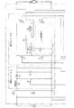
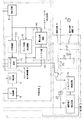
図1(a)及び1(b)は、本発明の第1実施形態による高輝度放電ランプ安定器を示す概略ブロック図である。高輝度放電ランプ安定器10(以下「安定器10」という)は、ランプ動作回路11、制御回路4及び補助回路5を含む。
1 (a) and 1 (b) are schematic block diagrams illustrating a high intensity discharge lamp ballast according to a first embodiment of the present invention. The high-intensity discharge lamp ballast 10 (hereinafter referred to as “
ランプ動作回路11は、整流器(DB1)、昇圧コンバータ1及び極性反転型の降圧コンバータ2を含む。整流器(DB1)は、電源電圧(Vs)を持つ商用AC電源(以下単に「電源」という)から供給されるAC電圧を整流する。昇圧コンバータ1は、スイッチング素子(Q1)を含み、整流器(DB1)からの電圧をDC電圧(VDC1)に変換する。また、昇圧コンバータ1は、入力力率を増大して、入力電流ひずみを防止する。降圧コンバータ2は、共振回路3及びスイッチング素子(Q2)〜(Q5)を含み、DC電圧(VDC1)を、高輝度放電ランプ(以下「HIDランプ」という)(La)に印加されるべき方形波AC電圧に変換する。降圧コンバータ2は、HIDランプ(La)の動作を開始するための始動電力モード及びHIDランプ(La)を安定に動作するための安定電力モードを含むマルチ・モードの動作を持つ。共振回路3は、パルス・トランス(PT1)及びキャパシタ(C3)を含み、パルス・トランス(PT1)は、1次巻線(n1)及び2次巻線(n2)を持つ。また、共振回路3は、共振周波数(fr)を持ち、共振昇圧電圧を、HIDランプ(La)を始動又は再始動するためにHIDランプ(La)に供給する。
The lamp operation circuit 11 includes a rectifier (DB1), a
制御回路4は、VDC1検出器4a、Q1制御器4b、検出回路4c、ランプ状態決定回路4d、スロー・リーク検出回路4e及びスイッチング素子制御器4fを含み、スイッチング素子(Q1)〜(Q5)を制御する。VDC1検出器4aは、昇圧コンバータ1の出力電圧を検出するように構成される。Q1制御器4bは、VDC1検出器4aによって検出された出力電圧に基づいて、スイッチング素子(Q1)を制御するように構成される。検出回路4c(ランプ電圧検出器)は、HIDランプ(La)に印加されるランプ電圧(Vla)を検出するように構成される。ランプ状態決定回路4d(ランプ状態決定部)は、検出回路4cによって検出されたランプ電圧(Vla)に基づいて、HIDランプ(La)が光を発生するオンされた状態にあるかどうかを決定するように構成される。スロー・リーク検出回路4e(スロー・リーク検出器)は、電圧比較回路4e1及びタイマ回路4e2を含み、HIDランプ(La)におけるスロー・リークを検出するように構成される。HIDランプ(La)は、ガスを充填される発光管を含むが、少量のガスが発光管から漏れることがある。ここで、スロー・リークは、HIDランプ(La)のランプ電圧(Vla)がそのような少量のガス漏れのためにランプの定格電圧に達しない状態をいう。電圧比較回路4e1(ランプ電圧比較器)は、ランプ電圧(Vla)を予め決定されたしきい電圧(Vsl)と比較するように構成される。スロー・リーク検出回路4eは、ランプ電圧(Vla)が予め決められた長さの時間を越える期間の間しきい電圧(Vsl)よりも低いままであるときにスロー・リークがあることを決定し、安定器10の動作を停止するようにスイッチング素子制御器4fに信号を送る。応じて、スロー・リーク検出回路4eは、スロー・リークが起こりHIDランプ(La)が低ランプ電圧及び大ランプ電流でオンされたままであるときの安定器10における異常温度増大を防ぐ。スイッチング素子制御器4fは、計算回路4f1及びスイッチング回路4f2を含む。計算回路4f1は、検出回路4cによって検出されたランプ電圧(Vla)に基づいて、スイッチング素子(Q4)及び(Q5)の「ON」期間の長さ及び周波数を決定するように構成される。スイッチング回路4f2は、降圧コンバータ2のモードを始動電力モードと安定電力モードとの間で切り替えるように構成される。降圧コンバータ2が安定電力モードで動作しているとき、スイッチング素子(Q2)〜(Q5)は、スイッチング回路4f2を介して計算回路4f1から出力される信号によって制御される。
The control circuit 4 includes a
補助回路5は、トライアック(Q51)、トライアック制御回路(5a)、電源電圧検出回路5b(電源電圧検出器、電圧比較部)及びOR回路6を含み、補助ランプ(IL)に接続される端子を持つ。補助ランプ(IL)は、白熱電球、ハロゲン・ランプまたは他のランプであってもよい。トライアック(Q51)は、電源と補助ランプ(IL)の端子との間に接続される双方向ゲート制御スイッチング素子である。電源電圧検出回路5bは、電源の電源電圧(Vs)を検出し、その検出した電圧を予め決められた基準電圧(Vsv)と比較し、それに応じてトライアック(Q51)を制御するトライアック制御回路5aに比較結果を出力する。
The auxiliary circuit 5 includes a triac (Q51), a triac control circuit (5a), a power supply
図1(a)及び1(b)を参照しながら、安定器10の動作を以下に述べる。
The operation of the
ランプ動作回路11は、電源からAC電圧を受け、整流器(DB1)によって整流された電圧が昇圧コンバータ1に入力される。昇圧コンバータ1から出力されるDC電圧(VDC1)に基づいて、制御回路4は、HIDランプ(La)がオン又はオフされる間、DC電圧(VDC1)が予め決められた電圧(Va)になるように、数十kHzの周波数でスイッチング素子(Q1)をオン及びオフする。電圧(Va)が予め決められた電圧(Va)になるとき、降圧コンバータ2は、始動電力モードにおける動作を開始する。この時点では、HIDランプ(La)がオフされていて、その等価インピーダンスは、ほぼ開状態に定まる。始動電力モードの降圧コンバータ2において、スイッチング素子(Q2)及び(Q5)が「ON」である第1期間とスイッチング素子(Q3)及び(Q4)が「ON」である第2期間とが、予め決められた周波数(f0)で交互に繰り返される。周波数(f0)は、例えば約数百kHzである。周波数(f0)は、共振周波数(fr)近くに設定され、正弦波高電圧が1次巻線(n1)に生成される。この高電圧は、パルス・トランス(PT1)の1次/2次巻線比によって増大されて、キャパシタ(C4)を介してHIDランプ(La)に供給され、絶縁破壊の結果として、HIDランプ(La)が動作を開始する。HIDランプ(La)がその動作を開始するとき、そのインピーダンスが短絡状態としてより低くなり、HIDランプ(La)のランプ電圧(Vla)は、約0Vになる。ランプ状態決定回路4dは、検出回路4cによって検出されたランプ電圧(Vla)に基づいて、HIDランプ(La)がオン又はオフされるかを決定する。より具体的には、HIDランプ(La)がオフである間、ランプ状態決定回路4dはH信号を出力するが、HIDランプ(La)がオンされてランプ電圧(Vla)がしきい電圧(図2に示すランプ状態決定しきい電圧)より低くなるとき、ランプ状態決定回路4dは、HIDランプ(La)がオンされたことを決定し、スイッチング素子制御器4fのスイッチング回路4f2にL信号を出力する。次いで、スイッチング回路4f2は、安定点灯出力でHIDランプ(La)を動作するための安定電力モードに降圧コンバータ2を切り替える。このモードでは、スイッチング素子(Q2)及び(Q3)が、予め決められた周波数(fa)で交互にオンされる。スイッチング素子(Q2)がオンである間、スイッチング素子(Q5)は、予め設定された周波数(fb)でオン及びオフされ、スイッチング素子(Q3)がオンである間、スイッチング素子(Q4)は、予め設定された周波数(fb)でオン及びオフされる。周波数(fa)は、例えば約数百Hzであり、周波数(fb)は、例えば約数十kHzである。結果として、HIDランプ(La)は、周波数(fa)を持つ方形波AC電圧を受ける。HIDランプ(La)のランプ電圧(Vla)はその動作の開始直後まだ低いが、HIDランプ(La)の内部温度及び圧力がより高くなるにつれてランプ電圧(Vla)が増大し、次いでHIDランプ(La)はその定格電圧で安定動作に達する。検出回路4cによって検出されたランプ電圧(Vla)に基づいて、計算回路4f1が、適した電力をHIDランプ(La)に供給するためにスイッチング素子(Q4)及び(Q5)のオン期間の長さ及び周波数を決定し、その決定した周波数及び長さに応じて、スイッチング回路4f2が、スイッチング素子(Q4)及び(Q5)をオン及びオフし、それによりHIDランプ(La)を安定に動作させる。
The lamp operation circuit 11 receives an AC voltage from the power supply, and the voltage rectified by the rectifier (DB1) is input to the
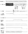
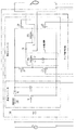
図2は、電源の電源電圧(Vs)が実質的に補助ランプ(IL)の定格電圧に等しい場合における安定器10の動作を示すシーケンス図である。図2は、上から下にかけて、電源の電源電圧(Vs)、ランプ電圧(Vla)、HIDランプ(La)を流れるランプ電流、ランプ状態決定回路4d、タイマ回路4e2、電圧比較回路4e1、電源電圧検出回路5b及びトライアック制御回路5aの各出力、及び補助ランプ(IL)に印加される電圧を示す。図2に示すように、HIDランプ(La)は、初めに例えば約数百kHzの高周波数を持つ高電圧を受けながら「OFF」であり、降圧コンバータ2は、始動電力モードで動作している。この時点で、ランプ状態決定回路4dは、HIDランプ(La)がオフしていることを示すH信号を出力する。電源電圧検出回路5bは、電源電圧(Vs)を検出し、その検出した電圧を予め決められた基準電圧(Vsv)と比較する。この場合、検出した電圧は基準電圧(Vsv)よりも小さいので、電源電圧検出回路5bは、H信号をトライアック制御回路5aに出力し、トライアック制御回路5aは、DC信号をトライアック(Q51)用のゲート信号として作成する。ランプ状態決定回路4dによって生成されたHIDランプ(La)の「OFF」状態を示すH信号は、補助回路5中のOR回路6に入力され、このH信号に基づいて、トライアック制御回路5aは、DC信号をトライアック(Q51)に供給する。DC信号はトライアック(Q51)をオンし、補助ランプ(IL)は電源電圧(Vs)に実質的に等しい電圧を受ける。一定期間の間、高周波を持つ高電圧を受けた後、HIDランプ(La)が始動され、ランプ電圧(Vla)が増大される。ランプ状態決定回路4dは、検出したランプ電圧(Vla)を予め決められたしきい電圧(Vst)と比較し、検出したランプ電圧(Vla)がしきい値よりも低いとき、ランプ状態決定回路4dは、HIDランプ(La)がオンされたことを決定し、その出力をH信号からL信号に切り替える。このL信号を受けたとき、降圧コンバータ2は、始動電力モードから安定電力モードに動作モードを変える。スロー・リーク検出回路4eの電圧比較回路4e1は、HIDランプ(La)が動作し始めるまでL信号を出力する。HIDランプ(La)がオンされ、ランプ電圧(Vla)がスロー・リーク検出しきい電圧(Vsl)を下回るとき、電圧比較回路4e1は、L信号からH信号に出力を切り替える。H信号の受信時、タイマ回路4e2は、時間を計測し始める。電圧比較回路4e1からのH信号は、OR回路6に入力され、トライアック制御回路5aは、ゲート信号としてのDC信号をトライアック(Q51)に供給する。トライアック(Q51)はオンされ、電源電圧(Vs)に実質的に等しい電圧は、補助ランプ(IL)に印加されたままである。降圧コンバータ2が安定電力モードで動作し始め、HIDランプ(La)のランプ電圧(Vla)が図2に示すようにしきい電圧(Vsl)を超えた後、電圧比較回路4e1はH信号からL信号に出力を切り替え、OR回路6が、ランプ状態決定回路4d及び電圧比較回路4e1の双方からL信号を受けるので、トライアック制御回路5aは、ゲート信号をトライアック(Q51)に供給するのを停止して、トライアック(Q51)をオフする。結果として、補助ランプ(IL)への電力供給が停止されて、補助ランプ(IL)がオフされる。
FIG. 2 is a sequence diagram showing the operation of the
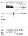
電源の電源電圧(Vs)が補助ランプ(IL)の定格電圧よりも高いとき、安定器10は、別の方法で動作する。図3は、電源の電源電圧(Vs)が補助ランプ(IL)の定格電圧よりも高い場合の安定器10の動作を示すシーケンス図である。図2と違って、電源電圧検出回路5bは、検出した電源電圧が予め決められた基準電圧(Vsv)よりも高いことを示すL信号を出力する。このL信号に基づいて、トライアック制御回路5aは、固定位相での電源電圧の位相制御用に、トライアック(Q51)に供給されるゲート信号として固定幅のパルスを作成する。HIDランプ(La)がオフされる間、ランプ状態決定回路4dはOR回路6へのH信号を生成し、その結果としてトライアック制御回路5aは、パルスをトライアック(Q51)に供給し、補助ランプ(IL)の定格電圧に実質的に等しい電圧を補助ランプ(IL)に印加するために固定位相でトライアック(Q51)をオン/オフする。電源電圧(Vs)が補助ランプ(IL)の定格電圧よりも高いかどうかを決定するのに電源電圧検出回路5bが使用する予め決められた基準電圧(Vsv)について、基準電圧(Vsv)は、補助ランプ(IL)の定格電圧に実質的に等しい電源電圧を持つ電源の許容最大電圧であってもよい。例えば、120VのAC電圧の場合には、電圧は約108Vから約132Vまでの範囲の中で変動してもよく、その許容最大電圧は約132Vである。電源電圧のそのような変動のために、基準電圧(Vsv)は、補助ランプの定格電圧に実質的に等しい電源電圧よりも約10%大きくて良い。代わりに、基準電圧(Vsv)は、補助ランプ(IL)の定格電圧の許容最大電圧であってもよい。例えば、120Vの定格電圧を持つ補助ランプ(IL)については、許容最大電圧は約140Vである。この場合、基準電圧(Vsv)は、電源電圧よりもたとえそれが変動したとしても十分に高いので、電源電圧決定回路5bは、電源電圧が補助ランプ(IL)の定格電圧よりも高いかどうかをより正確に決定し、その結果として補助回路5は、補助ランプILに高電圧で損害を与えることなく補助ランプ(IL)をより適切に動作する。また、基準電圧(Vsv)が、電源電圧の変動を考慮して上記の如く好ましく設定されるので、基準電圧(Vsv)が、例えば120Vの定格電圧を持つ補助ランプ(IL)用に140Vに設定され、電源電圧(Vs)が変動するものの基準電圧(Vsv)を超えないとき、電源電圧(Vs)は、減じた電圧を補助ランプ(IL)に印加する位相制御されない。その結果として、補助ランプ(IL)は、補助ランプ(IL)用の許容電圧範囲内のより高い電圧を受けながら、十分な点灯出力を生成する。
When the power supply voltage (Vs) of the power supply is higher than the rated voltage of the auxiliary lamp (IL), the
HIDランプ(La)がオンされた後、安定器11の動作は、図2の場合と同様である。図3に示すように、ランプ電圧(Vla)がリークしきい値(Vsl)に達するまで、電圧比較回路4e1は、H信号をOR回路6に出力し、その結果としてトライアック回路5aは、DC信号を供給してトライアック(Q51)をオンする。HIDランプ(La)が安定電力モードで動作させる間で、ランプ電圧(Vla)がリークしきい値(Vsl)を超えるとき、電圧比較回路4e1は、H信号からL信号に出力を切り替える。ランプ状態決定回路4d及び電圧比較回路4e1から入力されるL信号に基づいて、トライアック制御回路5aは、ゲート信号をトライアック(Q51)に供給するのを停止して、トライアック(Q51)をオフする。結果として、補助ランプ(IL)への電力供給が停止されて、補助ランプ(IL)がオフされる。
After the HID lamp (La) is turned on, the operation of the ballast 11 is the same as in the case of FIG. As shown in FIG. 3, the voltage comparison circuit 4e1 outputs the H signal to the OR circuit 6 until the ramp voltage (Vla) reaches the leak threshold (Vsl). As a result, the
図4を参照しながら、どのように安定器10がHIDランプ(La)のスロー・リークを検出し、HIDランプ(La)への電力供給を停止するかを以下に述べる。この場合、電源電圧(Vs)は補助ランプ(IL)の定格電圧よりも高く、その結果として安定器10の動作は、HIDランプ(La)がその動作を開始するまで図3に示す動作と同様である。HIDランプ(La)が一旦オンされると、スロー・リーク検出回路4eは、タイマ回路4e2で時間を計測し、検出したランプ電圧(Vla)をしきい電圧(Vsl)と比較することによって、HIDランプ(La)にスロー・リークがあるかを検査し始める。図4の場合には、HIDランプ(La)のスロー・リークのため、ランプ電圧(Vla)は、しきい電圧(Vsl)に達しない。タイマ回路4e2によって計測された時間が、予め決められた長さの時間を超え、検出したランプ電圧(Vla)がしきい電圧(Vsl)よりもまだ低いとき、スロー・リーク検出回路4eは、HIDランプ(La)にスロー・リークがあることを決定し、L信号からH信号にその出力を切り替える。スイッチング回路4f2は、このH信号を受けて、HIDランプ(La)への電力供給を停止するために降圧コンバータ2をオフする。降圧コンバータ2がHIDランプ(La)に電力を供給するのを停止するとき、ランプ電圧(Vla)は実質的にゼロに等しくなる。電圧比較回路4e1は、H信号をOR回路6に出力し続けて、トライアック制御回路5aは、トライアック(Q51)をオンするためにパルスをトライアック(Q51)に供給する。結果として、補助ランプ(IL)は、電源電圧(Vs)の位相制御によって生成された補助ランプ(IL)の定格電圧に実質的に等しい効果的な電圧を受けながら、オンされたままである。
With reference to FIG. 4, how the
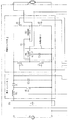
図5(a)及び5(b)は、本発明の第2実施形態による高輝度放電ランプを例示するブロック図である。高輝度放電ランプ安定器20(以下、単に「安定器20」という)は、電力切断回路21を除き安定器10の前述の補助回路5と同様の構成を持つ補助回路25を含む。電力切断回路21(電力切断部)は、フューズ(F51)(切断部)、トライアック(Q52)、抵抗(R51)、キャパシタ(C51)及び電圧感知双方向スイッチ(以下、単に「スイッチ」という)(Q55)を持つ。抵抗(R51)及びキャパシタ(C51)は、補助ランプ電圧検出器として働く。フューズ(F51)は、補助ランプ(IL)とトライアック(Q51)との間に置かれ、トライアック(Q52)は、補助ランプ(IL)と並列に、フューズ(F51)と補助ランプ(IL)との間に置かれる。抵抗(R51)、キャパシタ(C51)及びスイッチ(Q55)は、トライアック(Q52)の制御回路として具備される。補助回路25が本実施形態におけるそのような構成を持つので、たとえ極端に高い電圧がトライアック(Q51)の不具合によって或いは電源電圧異常によって生成され、その高い電圧が補助ランプ(IL)に印加されるとしても、補助回路25は、補助ランプ(IL)に電力を供給するのを停止し、補助ランプ(IL)がその高い電圧によって破壊されるのを防止する。
FIGS. 5A and 5B are block diagrams illustrating a high-intensity discharge lamp according to a second embodiment of the invention. The high-intensity discharge lamp ballast 20 (hereinafter simply referred to as “ballast 20”) includes an
図6を参照しながら、トライアック(Q51)の不具合の場合にどのように補助回路25が補助ランプ(IL)への電力供給を停止するのかを以下に述べる。電源の電源電圧(Vs)が補助ランプ(IL)の定格電圧よりもかなり高く、短絡がトライアック(Q51)に起こるとき、電源電圧(Vs)は適切に位相制御されず、その結果として過度に高い電圧が補助ランプ(IL)に印加される。図6の場合、トライアック(Q51)は最初適切に動作するが、後の不具合の結果として、キャパシタ(C51)の充電時間がより長くなり、充電の間のキャパシタ電圧が、トライアック(Q51)が不具合無く動作するときよりも高くなる。本発明のこの実施形態による安定器20において、スイッチ(Q55)の応答電圧は、トライアック(Q51)が適切に動作するときにキャパシタ(C51)に充電される電圧よりも高いが、トライアック(Q51)が短絡されるときにキャパシタ(C51)に充電される電圧よりも低くなるように設定される。従って、トライアック(Q51)が短絡を持つとき、スイッチ(Q55)がオンされ、電流が、補助ランプ(IL)の両端を短絡するトライアック(Q52)のゲート端子に流入する。短絡のため、過度に大きい電流が電源から補助回路25に供給され、フューズ(F51)が溶けて、補助回路(IL)への電力供給が停止される。それ故に、本実施形態の安定器20は、補助ランプ(IL)が破壊されるのをより効果的に防止する。なお、そのような防止制御が利用できない補助回路においては、補助ランプの破壊が避けられないかもしれないから、特にハロゲン・ランプが補助ランプとして使用される場合には非常に危険となる。
With reference to FIG. 6, how the
図7(a)及び7(b)は、本発明の第3実施形態による高輝度放電ランプを示すブロック図である。高輝度放電ランプ安定器30(以下、単に「安定器30」という)は、電力低減回路32を除き安定器20の前述の補助回路25と同様の構成を持つ補助回路35を有する。電力低減回路32(電力低減部)は、キャパシタ(C51)及び(C52)、トライアック(Q53)、抵抗(R51)、(R52)及び(R53)、トライアック(Q54)、及び電圧感知双方向スイッチ(以下、単に「スイッチ」という)(Q55)を持つ。抵抗(R51)及びキャパシタ(C51)は、補助ランプ電圧検出器として働く。キャパシタ(C52)は、補助ランプ(IL)とトライアック(Q51)との間に置かれ、トライアック(Q53)は、キャパシタ(C52)の両端を接続/切断するように置かれる。抵抗(R52)及び(R53)、及びトライアック(Q54)は、トライアック(Q53)の制御回路として具備される。また、抵抗(R51)、キャパシタ(C51)及びスイッチ(Q55)は、トライアック(Q54)の制御回路として具備される。補助回路35は本実施形態におけるそのような構成を持つので、たとえ極端に高い電圧がトライアック(Q51)の不具合によって或いは電源電圧異常によって生成され、その高い電圧が補助ランプ(IL)に印加されるとしても、電力低減回路32が補助ランプ(IL)への電力供給を低減し、補助ランプ(IL)がその高い電圧によって破壊されるのを防止する。
FIGS. 7A and 7B are block diagrams showing a high-intensity discharge lamp according to a third embodiment of the present invention. The high-intensity discharge lamp ballast 30 (hereinafter simply referred to as “ballast 30”) has an auxiliary circuit 35 having the same configuration as the
図8を参照しながら、トライアック(Q51)の不具合の場合にどのように電力低減回路32が補助ランプ(IL)への電力供給を低減するかを以下に述べる。電源の電源電圧(Vs)が補助ランプ(IL)の定格電圧よりもかなり高く、短絡がトライアック(Q51)に起こるとき、電源電圧(Vs)は適切に位相制御されず、その結果として過度に高い電圧が補助ランプ(IL)に印加される。図8の場合には、トライアック(Q51)は最初適切に動作するから、トライアック(Q53)はオンされ、位相制御電圧が補助ランプ(IL)に印加される。しかし、トライアック(Q51)が短絡及び不具合であるとき、トライアック(Q53)がオンされるので、電源電圧(Vs)に実質的に等しい高電圧が補助ランプ(IL)に印加される。結果として、キャパシタ(C51)の充電時間がより長くなり、充電の間のキャパシタ電圧が、トライアック(Q51)が不具合無く動作するときよりも高くなる。スイッチ(Q55)の応答電圧は、トライアック(Q51)が適切に動作するときのキャパシタ充電電圧よりも高いが、トライアック(Q51)が短絡されるときのキャパシタ充電電圧よりも低くなるように設定される。従って、トライアック(Q51)が短絡をもつとき、スイッチ(Q55)がオンされ、電流がトライアック(Q54)のゲート端子に流入し、トライアック(Q54)をオンする。トライアック(Q53)のゲート端子が短絡され、トリガ電流がそのゲート端子に流入しない。このように、トライアック(Q53)がオフされる。結果として、キャパシタ(C52)がトライアック(Q51)と補助ランプ(IL)との間に挿入され、電源電圧(Vs)がキャパシタ(C52)及び補助ランプ(IL)のインピーダンスによって分配される。それ故、低減された電圧が補助ランプ(IL)に印加される。この方法において、安定器30の補助回路35は、補助ランプ(IL)への極端に高い電圧の印加をより効果的に防止し、さもなければ逆に補助ランプ(IL)の動作に影響を及ぼす。 Referring to FIG. 8, how the power reduction circuit 32 reduces the power supply to the auxiliary lamp (IL) in the case of a malfunction of the triac (Q51) will be described below. When the power supply voltage (Vs) of the power supply is significantly higher than the rated voltage of the auxiliary lamp (IL) and a short circuit occurs in the triac (Q51), the power supply voltage (Vs) is not properly phased and consequently excessively high A voltage is applied to the auxiliary lamp (IL). In the case of FIG. 8, since the triac (Q51) operates properly at first, the triac (Q53) is turned on and the phase control voltage is applied to the auxiliary lamp (IL). However, when the triac (Q51) is short-circuited and malfunctioned, the triac (Q53) is turned on, so that a high voltage substantially equal to the power supply voltage (Vs) is applied to the auxiliary lamp (IL). As a result, the charging time of the capacitor (C51) becomes longer, and the capacitor voltage during charging becomes higher than when the triac (Q51) operates without malfunction. The response voltage of the switch (Q55) is set to be higher than the capacitor charging voltage when the triac (Q51) operates properly, but lower than the capacitor charging voltage when the triac (Q51) is short-circuited. . Therefore, when the triac (Q51) has a short circuit, the switch (Q55) is turned on, and the current flows into the gate terminal of the triac (Q54) to turn on the triac (Q54). The gate terminal of the triac (Q53) is short-circuited, and the trigger current does not flow into the gate terminal. In this way, the triac (Q53) is turned off. As a result, the capacitor (C52) is inserted between the triac (Q51) and the auxiliary lamp (IL), and the power supply voltage (Vs) is distributed by the impedance of the capacitor (C52) and the auxiliary lamp (IL). Therefore, a reduced voltage is applied to the auxiliary lamp (IL). In this way, the auxiliary circuit 35 of the ballast 30 more effectively prevents the application of extremely high voltages to the auxiliary lamp (IL), otherwise it adversely affects the operation of the auxiliary lamp (IL). .
上述の如く、本発明の実施形態による安定器において、トライアック制御器は、HIDランプに電力が供給され、HIDランプがオンされた状態にないことをランプ状態決定回路が決定したとき、補助ランプの定格電圧に実質的に等しい電圧を補助ランプに印加するようにトライアックを制御する。それ故に、安定器は、電源の電圧に関係なく、定格電圧に実質的に等しい電圧で補助ランプを適切にオンする。応じて、電源の電源電圧に依存しながら異なって設計される安定器の状況とは違って、本発明の実施形態による安定器のインベントリ制御は非常により容易であり、生産性がかなり増大される。しかし、図9、10(a)及び10(b)に示すような補助点灯装置の場合には、装置は、選択された電圧のみと互換性がある。より具体的には、図10(a)及び10(b)に示す補助点灯装置は、リレー回路(Ry1)、電源と白熱電球との間に接続される一対の端子(T1a)及び(T1b)、及びHIDランプと安定器との間に接続される一対の端子(T2a)及び(T2b)を持つ。励起ワイヤ(M1)は端子(T2a)及び(T2b)間に、主スイッチ(S1)は端子(T1a)及び(T1b)の間に接続される。リレー回路(Ry1)において、電流が励起ワイヤ(M1)を通って流れるとき、主スイッチ(S1)はオフされ、電流が流れない間は、主スイッチ(S1)はオンされる。高輝度放電ランプがオフされるとき、電流が励起ワイヤ(M1)を通って流れないので、主スイッチ(S1)がオンされ、白熱電球が電源から電力を受ける。一旦、高輝度放電ランプがオンされ、電流が励起ワイヤ(M1)を通って流れると、主スイッチ(S1)がオフされるから、白熱電球への電力供給が停止され、白熱電球がオフされる。しかし、図11(a)及び11(b)に示すように、補助点灯装置は、電源電圧(AC277V)を白熱電球の定格電圧(AC120V)に低減するためのトランスを必要とする。それに反して、本発明の実施形態による安定器は、HIDランプがオフされることをランプ状態決定回路が決定するときに、補助ランプの定格電圧に実質的に等しい電圧を補助ランプに印加するために、トライアックを制御するように構成される制御器を有するから、安定器は、より小さく複雑でない構造を持つ。 As described above, in the ballast according to the embodiment of the present invention, the triac controller is configured such that when power is supplied to the HID lamp and the lamp state determination circuit determines that the HID lamp is not turned on, the auxiliary lamp The triac is controlled so that a voltage substantially equal to the rated voltage is applied to the auxiliary lamp. Therefore, the ballast properly turns on the auxiliary lamp at a voltage substantially equal to the rated voltage, regardless of the voltage of the power supply. Accordingly, unlike ballast situations that are designed differently depending on the power supply voltage of the power supply, inventory control of the ballast according to embodiments of the present invention is much easier and productivity is significantly increased. . However, in the case of an auxiliary lighting device as shown in FIGS. 9, 10 (a) and 10 (b), the device is compatible only with the selected voltage. More specifically, the auxiliary lighting device shown in FIGS. 10 (a) and 10 (b) includes a relay circuit (Ry1), a pair of terminals (T1a) and (T1b) connected between a power source and an incandescent bulb. And a pair of terminals (T2a) and (T2b) connected between the HID lamp and the ballast. The excitation wire (M1) is connected between the terminals (T2a) and (T2b), and the main switch (S1) is connected between the terminals (T1a) and (T1b). In the relay circuit (Ry1), when the current flows through the excitation wire (M1), the main switch (S1) is turned off, and the main switch (S1) is turned on while no current flows. When the high intensity discharge lamp is turned off, no current flows through the excitation wire (M1), so the main switch (S1) is turned on and the incandescent bulb receives power from the power source. Once the high-intensity discharge lamp is turned on and the current flows through the excitation wire (M1), the main switch (S1) is turned off, so the power supply to the incandescent bulb is stopped and the incandescent bulb is turned off. . However, as shown in FIGS. 11 (a) and 11 (b), the auxiliary lighting device requires a transformer for reducing the power supply voltage (AC277V) to the rated voltage (AC120V) of the incandescent lamp. In contrast, the ballast according to embodiments of the present invention applies a voltage to the auxiliary lamp that is substantially equal to the rated voltage of the auxiliary lamp when the lamp state determination circuit determines that the HID lamp is turned off. Since the ballast has a controller configured to control the triac, the ballast has a smaller and less complex structure.
明らかに、本発明の多数の修正及び変形が上記内容に鑑みて可能である。従って、添付した特許請求の範囲内において、本発明が、ここに明確に記述したものとは別のやり方でなされても良いことが理解される。 Obviously, many modifications and variations of the present invention are possible in light of the above. It is therefore to be understood that within the scope of the appended claims, the invention may be practiced otherwise than as specifically described herein.
10 高輝度放電ランプ安定器
11 ランプ動作回路
1 昇圧コンバータ
2 降圧コンバータ
3 共振回路
4 制御回路
4a VDC1検出器
4b Q1制御器
4c 検出回路
4d ランプ状態決定回路
4e スロー・リーク検出回路
4e1 電圧比較回路
4e2 タイマ回路
4f スイッチング素子制御器
4f1 計算回路
4f2 スイッチング回路
5,25,35 補助回路
Q51 トライアック
5a トライアック制御回路
5b 電源電圧検出回路
6 OR回路
21 電力切断回路
32 電力低減回路
DESCRIPTION OF
Claims (17)
該高輝度放電ランプに印加される電圧を検出すように構成されるランプ電圧検知器と、
該ランプ電圧検知器によって検出された電圧に基づいて、該高輝度放電ランプがオンされた状態にあるかを決定するように構成されるランプ状態決定部と、
該電源と定格電圧を持つ補助ランプとを接続するように構成される補助ランプ・スイッチング素子と、
該高輝度放電ランプが該電力を供給され、該高輝度放電ランプが該オンされた状態にあることを該ランプ状態決定部が決定するとき、該補助ランプの定格電圧に実質的に等しい電圧を該補助ランプに印加するために該補助ランプ・スイッチング素子を制御するように構成される制御器と
を含む高輝度放電ランプ安定器。 A lamp operating unit configured to supply power from a power source to the high intensity discharge lamp;
A lamp voltage detector configured to detect a voltage applied to the high intensity discharge lamp;
A lamp state determination unit configured to determine whether the high intensity discharge lamp is in an on state based on a voltage detected by the lamp voltage detector;
An auxiliary lamp switching element configured to connect the power source and an auxiliary lamp having a rated voltage;
When the high-intensity discharge lamp is supplied with the power and the lamp state determination unit determines that the high-intensity discharge lamp is in the on state, a voltage substantially equal to the rated voltage of the auxiliary lamp is applied. And a controller configured to control the auxiliary lamp switching element for application to the auxiliary lamp.
該電源電圧検出器によって検出された電源電圧を予め決められた基準電圧と比較するように構成される電圧比較部とを更に含み、
該電源電圧が予め決められた基準電圧よりも高いことを該電圧比較部が決定するとき、該制御器は、該電源電圧を該補助ランプの定格電圧に実質的に等しいところに低減する該電圧の位相制御によって生成される電圧を該補助ランプに印加する
請求項1記載の高輝度放電ランプ安定器。 A power supply voltage detector configured to detect a power supply voltage of the power supply;
A voltage comparison unit configured to compare the power supply voltage detected by the power supply voltage detector with a predetermined reference voltage;
When the voltage comparator determines that the power supply voltage is higher than a predetermined reference voltage, the controller reduces the power supply voltage to be substantially equal to the rated voltage of the auxiliary lamp. The high-intensity discharge lamp ballast according to claim 1, wherein a voltage generated by the phase control is applied to the auxiliary lamp.
該高輝度放電ランプにスロー・リークがあることを該スロー・リーク検出器が決定するとき、該制御器は、該補助ランプ・スイッチング素子をオンする
請求項1記載の高輝度放電ランプ安定器。 Further comprising a slow leak detector configured to determine whether the high intensity discharge lamp has a slow leak based on the voltage detected by the lamp voltage detector;
The high intensity discharge lamp ballast of claim 1, wherein the controller turns on the auxiliary lamp switching element when the slow leak detector determines that there is a slow leak in the high intensity discharge lamp.
該タイマによって計測された時間が予め決められた基準の長さの時間を超えるとき、該スロー・リーク検出器は、該高輝度放電ランプにスロー・リークがあることを決定し、
該タイマが該時間を計測する間、該制御器は、該補助ランプの定格電圧に実質的に等しい電圧を該補助ランプに印加する
請求項6記載の高輝度放電ランプ安定器。 The slow leak detector includes a lamp voltage comparator configured to compare the voltage detected by the lamp voltage detector with a threshold value, and starting from a time when the high intensity discharge lamp begins to operate. A timer configured to measure a time when the voltage is less than the threshold;
When the time measured by the timer exceeds a predetermined reference length of time, the slow leak detector determines that the high intensity discharge lamp has a slow leak;
7. The high intensity discharge lamp ballast of claim 6, wherein the controller applies a voltage to the auxiliary lamp substantially equal to a rated voltage of the auxiliary lamp while the timer measures the time.
該補助ランプに印加される電圧を検出するように構成される補助ランプ電圧検出器と、
該補助ランプと並列に接続され、該補助ランプ電圧検出器によって検出された電圧が予め決められたしきい値よりも高いとき、オンされるように構成されるスイッチング素子と、
該スイッチング素子及び該補助ランプと直列に接続され、該スイッチング素子がオンされるとき、該補助ランプを該電源から切断するように構成される切断部と
を含む請求項11記載の高輝度放電ランプ安定器。 The power disconnection unit is
An auxiliary lamp voltage detector configured to detect a voltage applied to the auxiliary lamp;
A switching element connected in parallel with the auxiliary lamp and configured to be turned on when a voltage detected by the auxiliary lamp voltage detector is higher than a predetermined threshold;
The high-intensity discharge lamp according to claim 11, further comprising: a cutting part connected in series with the switching element and the auxiliary lamp and configured to disconnect the auxiliary lamp from the power source when the switching element is turned on. stabilizer.
該補助ランプに印加される電圧を検出するように構成される補助ランプ電圧検出器と、
該電源と該補助ランプとの間に置かれるインピーダンス要素と、
該インピーダンス要素と並列に接続され、該補助ランプ電圧検出器によって検出された電圧が予め決められたしきい値よりも高いとき、オフされるように構成されるスイッチング素子と
を含む請求項13記載の高輝度放電ランプ安定器。 The power reduction unit
An auxiliary lamp voltage detector configured to detect a voltage applied to the auxiliary lamp;
An impedance element placed between the power source and the auxiliary lamp;
14. A switching element connected in parallel with the impedance element and configured to be turned off when a voltage detected by the auxiliary lamp voltage detector is higher than a predetermined threshold. High intensity discharge lamp ballast.
該高輝度放電ランプに印加される電圧を検出するためのランプ電圧検出手段と、
該ランプ電圧検出手段によって検出された電圧に基づいて、該高輝度放電ランプがオンされた状態にあるかを決定するためのランプ状態決定手段と、
該電源と定格電圧を持つ補助ランプとを接続するための補助ランプ・スイッチング手段と、
該高輝度放電ランプが該電力を供給され、該高輝度放電ランプがオンされた状態にないことを該ランプ状態決定手段が決定するとき、該補助ランプの定格電圧に実質的に等しい電圧を該補助ランプに印加するように該補助ランプスイッチング手段を制御するための制御手段と
を含む高輝度放電ランプ安定器。 Lamp operating means for supplying power from the power source to the high-intensity discharge lamp;
Lamp voltage detection means for detecting a voltage applied to the high-intensity discharge lamp;
Lamp state determination means for determining whether the high-intensity discharge lamp is in an on state based on the voltage detected by the lamp voltage detection means;
Auxiliary lamp switching means for connecting the power source and an auxiliary lamp having a rated voltage;
When the lamp state determining means determines that the high intensity discharge lamp is supplied with the power and the high intensity discharge lamp is not in an on state, the voltage is substantially equal to the rated voltage of the auxiliary lamp. A high intensity discharge lamp ballast including control means for controlling the auxiliary lamp switching means to apply to the auxiliary lamp.
該高輝度放電ランプに印加される電圧を検出し、
検出した電圧に基づいて、該高輝度放電ランプがオンされた状態にあるかを決定し、
該電源と定格電圧を持つ補助ランプとを接続するように構成される補助ランプ・スイッチング素子を提供し、
該高輝度放電ランプが該電力を供給され、該高輝度放電ランプが該オンされた状態にあると決定されないとき、該補助ランプの定格電圧に実質的に等しい電圧を該補助ランプに供給するように該補助ランプ・スイッチング素子を制御する
ことを含む高輝度放電ランプを動作するための方法。 Supply power from the power source to the high-intensity discharge lamp,
Detecting a voltage applied to the high-intensity discharge lamp;
Based on the detected voltage, determine whether the high-intensity discharge lamp is on,
Providing an auxiliary lamp switching element configured to connect the power source and an auxiliary lamp having a rated voltage;
When the high-intensity discharge lamp is supplied with the power and it is not determined that the high-intensity discharge lamp is in the on state, it supplies the auxiliary lamp with a voltage substantially equal to the rated voltage of the auxiliary lamp. A method for operating a high intensity discharge lamp comprising: controlling the auxiliary lamp switching element.
Applications Claiming Priority (1)
| Application Number | Priority Date | Filing Date | Title |
|---|---|---|---|
| US10/991,415 US7109659B2 (en) | 2004-11-19 | 2004-11-19 | High-intensity discharge lamp ballast and method for operating high-intensity discharge lamp |
Publications (2)
| Publication Number | Publication Date |
|---|---|
| JP2006156376A true JP2006156376A (en) | 2006-06-15 |
| JP2006156376A5 JP2006156376A5 (en) | 2011-09-08 |
Family
ID=36460331
Family Applications (1)
| Application Number | Title | Priority Date | Filing Date |
|---|---|---|---|
| JP2005332055A Pending JP2006156376A (en) | 2004-11-19 | 2005-11-16 | High-brightness discharge lamp ballast and method of operating high-brightness discharge lamp |
Country Status (2)
| Country | Link |
|---|---|
| US (1) | US7109659B2 (en) |
| JP (1) | JP2006156376A (en) |
Families Citing this family (14)
| Publication number | Priority date | Publication date | Assignee | Title |
|---|---|---|---|---|
| US7279850B2 (en) * | 2003-04-09 | 2007-10-09 | Auckland Uniservices Ltd. | Decoupling circuits |
| US7265650B2 (en) * | 2005-02-22 | 2007-09-04 | Delta Electronics, Inc. | Power factor correction rectifier having independent inductive components |
| US7265501B2 (en) * | 2005-03-11 | 2007-09-04 | Protection Services Inc. | Mobile light |
| US7282863B2 (en) * | 2005-07-11 | 2007-10-16 | Varon Lighting Group, Llc | Auxiliary quartz lamp lighting system for electronic high intensity discharge lamp ballasts |
| US7276855B2 (en) * | 2005-07-15 | 2007-10-02 | General Electric Company | Auxilary lighting circuit for high intensity discharge system |
| US20070138971A1 (en) * | 2005-08-15 | 2007-06-21 | Liang Chen | AC-to-DC voltage converter as power supply for lamp |
| JP2007194044A (en) * | 2006-01-18 | 2007-08-02 | Koito Mfg Co Ltd | Lighting circuit |
| WO2009049674A1 (en) * | 2007-10-17 | 2009-04-23 | Osram Gesellschaft mit beschränkter Haftung | Electronic ballast and method for operating a discharge lamp |
| US7944156B2 (en) * | 2008-03-13 | 2011-05-17 | Energy Conservation Technologies, Inc. | Electronic ballast for high intensity discharge lamps |
| CN101888734B (en) * | 2009-05-13 | 2014-07-16 | 通用电气公司 | Electronic ballast of belt lifting/voltage reducing power-factor correction DC-DC converter |
| DE102010022001A1 (en) * | 2009-11-20 | 2011-05-26 | Diehl Ako Stiftung & Co. Kg | Circuit arrangement and method for providing a voltage supply for a driver circuit |
| CN202276534U (en) * | 2010-07-08 | 2012-06-13 | 皇家飞利浦电子股份有限公司 | Lamp driver |
| EP2666237A1 (en) * | 2011-01-21 | 2013-11-27 | Hulusi Bulent Ertan | Power-level waveform generation method |
| TWI437926B (en) * | 2011-03-28 | 2014-05-11 | Delta Electronics Inc | Multi-output electronic ballast |
Citations (8)
| Publication number | Priority date | Publication date | Assignee | Title |
|---|---|---|---|---|
| JPS58204490A (en) * | 1982-05-20 | 1983-11-29 | ミノルタ株式会社 | Lamp dimming circuit |
| JPS60198094A (en) * | 1984-03-21 | 1985-10-07 | セイコーエプソン株式会社 | Constant-light quantity light source |
| JPH05326172A (en) * | 1992-05-15 | 1993-12-10 | Matsushita Electric Works Ltd | Discharge lamp lighting device |
| JPH07114990A (en) * | 1993-10-14 | 1995-05-02 | Plus Kk | Halogen lamp dimmer |
| JPH09223587A (en) * | 1996-02-14 | 1997-08-26 | Koito Mfg Co Ltd | Discharge lamp lighting circuit |
| JPH10315846A (en) * | 1997-05-16 | 1998-12-02 | Denso Corp | Load drive device for vehicle |
| JP2001130314A (en) * | 1999-08-20 | 2001-05-15 | Miyata Ind Co Ltd | Lighting control system for bicycle |
| JP2001135492A (en) * | 1999-11-05 | 2001-05-18 | Victor Co Of Japan Ltd | Power-source device for lamp |
Family Cites Families (5)
| Publication number | Priority date | Publication date | Assignee | Title |
|---|---|---|---|---|
| US4034259A (en) * | 1976-04-14 | 1977-07-05 | Audio Visual Innovators Corporation | Spare lamp control circuit for a light projection system |
| AU747501B2 (en) * | 1998-09-18 | 2002-05-16 | Knobel Ag Lichttechnische Komponenten | Circuit for operating gas discharge lamps |
| US6448720B1 (en) * | 2001-03-30 | 2002-09-10 | Matsushita Electric Works R&D Laboratory, Inc. | Circuit for driving an HID lamp |
| US6489729B1 (en) * | 2001-06-11 | 2002-12-03 | Koninklijke Philips Electronics N.V. | Auxiliary lighting system for high intensity discharge lamp |
| JP3878823B2 (en) * | 2001-08-10 | 2007-02-07 | 株式会社小糸製作所 | Vehicle lamp device |
-
2004
- 2004-11-19 US US10/991,415 patent/US7109659B2/en not_active Expired - Fee Related
-
2005
- 2005-11-16 JP JP2005332055A patent/JP2006156376A/en active Pending
Patent Citations (8)
| Publication number | Priority date | Publication date | Assignee | Title |
|---|---|---|---|---|
| JPS58204490A (en) * | 1982-05-20 | 1983-11-29 | ミノルタ株式会社 | Lamp dimming circuit |
| JPS60198094A (en) * | 1984-03-21 | 1985-10-07 | セイコーエプソン株式会社 | Constant-light quantity light source |
| JPH05326172A (en) * | 1992-05-15 | 1993-12-10 | Matsushita Electric Works Ltd | Discharge lamp lighting device |
| JPH07114990A (en) * | 1993-10-14 | 1995-05-02 | Plus Kk | Halogen lamp dimmer |
| JPH09223587A (en) * | 1996-02-14 | 1997-08-26 | Koito Mfg Co Ltd | Discharge lamp lighting circuit |
| JPH10315846A (en) * | 1997-05-16 | 1998-12-02 | Denso Corp | Load drive device for vehicle |
| JP2001130314A (en) * | 1999-08-20 | 2001-05-15 | Miyata Ind Co Ltd | Lighting control system for bicycle |
| JP2001135492A (en) * | 1999-11-05 | 2001-05-18 | Victor Co Of Japan Ltd | Power-source device for lamp |
Also Published As
| Publication number | Publication date |
|---|---|
| US20060108940A1 (en) | 2006-05-25 |
| US7109659B2 (en) | 2006-09-19 |
Similar Documents
| Publication | Publication Date | Title |
|---|---|---|
| JP2006156376A (en) | High-brightness discharge lamp ballast and method of operating high-brightness discharge lamp | |
| JP4944899B2 (en) | Discharge lamp lighting device, lighting system, and method thereof | |
| JP5129651B2 (en) | High pressure discharge lamp lighting device and lighting fixture | |
| JP2004134360A (en) | Ballast for three-way dimming compact fluorescent lamp | |
| JP2008010155A (en) | Discharge lamp lighting device and illumination apparatus | |
| EP2278862B1 (en) | High pressure discharge lamp lighting device, and illumination fixture and illumination system using the same | |
| JP2010129234A (en) | High-pressure discharge lamp lighting device, luminaire, and illuminating system | |
| JP2010108657A (en) | Lighting device for discharge lamp and illumination equipment | |
| JP2007103290A (en) | High voltage discharge lamp lighting device | |
| JP4239808B2 (en) | High pressure discharge lamp lighting device and lighting fixture | |
| US6836078B2 (en) | Circuit for lighting HID lamp | |
| JPH04337294A (en) | Discharge lamp lighting device | |
| JP2010080138A (en) | High-pressure discharge lamp lighting device, and lighting fixture | |
| JP5139738B2 (en) | Discharge lamp lighting device and in-vehicle lighting apparatus | |
| JP2010257659A (en) | High-pressure discharge lamp-lighting device and lighting fixture using the same | |
| JP6350139B2 (en) | Discharge lamp lighting device, lighting device, and control method of discharge lamp lighting device | |
| EP2339897B1 (en) | High pressure discharge lamp lighting device and illumination fixture using the same | |
| KR100711812B1 (en) | The ballast for hid-lamp with contactless control | |
| JP2000294390A (en) | Power supply device capable of lighting a plurality of high-pressure discharge lamps | |
| JP5654852B2 (en) | Lighting device and lighting fixture using the same | |
| JPH10289789A (en) | Discharge lamp lighting device | |
| JP2012113881A (en) | Lighting device and luminaire using the same | |
| JP4899967B2 (en) | Discharge lamp lighting device, lighting fixture and lighting system | |
| JP4525446B2 (en) | Discharge lamp lighting device and lighting fixture | |
| JP2010055915A (en) | High pressure discharge lamp lighting device, light source device, and starting method of high pressure discharge lamp |
Legal Events
| Date | Code | Title | Description |
|---|---|---|---|
| A621 | Written request for application examination |
Free format text: JAPANESE INTERMEDIATE CODE: A621 Effective date: 20080806 |
|
| A977 | Report on retrieval |
Free format text: JAPANESE INTERMEDIATE CODE: A971007 Effective date: 20110301 |
|
| A131 | Notification of reasons for refusal |
Free format text: JAPANESE INTERMEDIATE CODE: A131 Effective date: 20110524 |
|
| A524 | Written submission of copy of amendment under article 19 pct |
Free format text: JAPANESE INTERMEDIATE CODE: A524 Effective date: 20110725 |
|
| A131 | Notification of reasons for refusal |
Free format text: JAPANESE INTERMEDIATE CODE: A131 Effective date: 20111206 |
|
| A711 | Notification of change in applicant |
Free format text: JAPANESE INTERMEDIATE CODE: A712 Effective date: 20120112 |
|
| A02 | Decision of refusal |
Free format text: JAPANESE INTERMEDIATE CODE: A02 Effective date: 20121002 |