JP2006154662A - Image forming apparatus - Google Patents
Image forming apparatus Download PDFInfo
- Publication number
- JP2006154662A JP2006154662A JP2004348869A JP2004348869A JP2006154662A JP 2006154662 A JP2006154662 A JP 2006154662A JP 2004348869 A JP2004348869 A JP 2004348869A JP 2004348869 A JP2004348869 A JP 2004348869A JP 2006154662 A JP2006154662 A JP 2006154662A
- Authority
- JP
- Japan
- Prior art keywords
- image forming
- corner
- connecting member
- reading unit
- unit
- Prior art date
- Legal status (The legal status is an assumption and is not a legal conclusion. Google has not performed a legal analysis and makes no representation as to the accuracy of the status listed.)
- Pending
Links
Images


Landscapes
- Electrophotography Configuration And Component (AREA)
Abstract
Description
本発明は、胴内排紙(機内排紙)タイプの画像形成装置に関する。 The present invention relates to an in-body discharge (in-machine discharge) type image forming apparatus.
近年、オフィスの省スペース化の流れが進んでいる。これに伴い、通常使用時の操作スペースを抑える事の可能な胴内排紙(機内排紙)タイプの画像形成装置の需要が高まっている。胴内排紙タイプとは、上下に離間して配置されたイメージスキャナとプリンタ本体の間に排紙トレイが設けられた構成である。 In recent years, there has been a trend toward office space saving. Along with this, there is an increasing demand for in-body discharge (in-machine discharge) type image forming apparatuses capable of reducing the operation space during normal use. The in-body discharge type is a configuration in which a discharge tray is provided between an image scanner and a printer main body that are spaced apart from each other in the vertical direction.
通常、胴内に排紙トレイを配置すると、トレイがイメージスキャナやプリンタ本体のフレームの陰になり易く、ユーザからの出力紙の視認性やアクセス性が低下する。このようなユーザビリティの低下を極力改善する目的で、例えば、本体4隅のうちのいずれかについてイメージスキャナの支持部を省略することによって、画像形成装置の4側面のうち、2側面およびその挟角方向から排紙トレイにアクセス可能にする構成が採用されている(特許文献1〜3参照)。
しかしながら、イメージスキャナの支持個所を省略すると、省略個所が片持ち支持の自由端になるため、イメージスキャナの支持強度が低下するという問題がある。イメージスキャナは、ユーザが直接操作する部分であるが故に外力を受け易い上、読取性能面で外力の影響が現れやすい。よって、品質を保証する上で十分な支持強度を確保する必要がある。 However, if the supporting portion of the image scanner is omitted, the omitted portion becomes the free end of the cantilever support, so that there is a problem that the supporting strength of the image scanner is lowered. Since the image scanner is a part that is directly operated by the user, the image scanner is easily subjected to external force and the influence of the external force is likely to appear on the reading performance. Therefore, it is necessary to ensure a sufficient support strength for assuring quality.
この強度問題に対する対策は、従来からいくつか提案されている。一つには、イメージスキャナをプリンタ本体の構造体に直接取り付けるのではなく、専用のラックに載せて、このラック内部にプリンタ本体を収納するという方式や、同様のラック状フレームを、プリンタ本体の背面や側面に固定する方式がある。この方式では、イメージスキャナの支持強度は確保されるものの、専用の大型のラックを用いる為、物流・設置面で弊害がある他、ラック内部にプリンタ部を収納した弊害として、部品交換やメンテナンス等のサービス性やジャム処理性が悪化する問題がある。また、イメージスキャナを支持するラックは、重心位置が高くなる為、通常の読取動作でイメージスキャナのミラー台が駆動されると、その際の駆動反力でラック全体が揺れる等の問題もある。 Several countermeasures for this strength problem have been proposed. For one, the image scanner is not directly attached to the printer body structure, but is mounted on a dedicated rack and the printer body is housed inside the rack, or a similar rack frame is mounted on the printer body. There is a method to fix to the back and side. In this method, the support strength of the image scanner is ensured, but since a dedicated large rack is used, there are problems in terms of logistics and installation, as well as problems such as parts replacement and maintenance, etc. that are housed in the rack. There is a problem that the serviceability and the jam handling property of the product deteriorate. Further, since the rack supporting the image scanner has a high center of gravity, there is a problem that when the mirror stage of the image scanner is driven by a normal reading operation, the entire rack is shaken by the driving reaction force at that time.
一方、よりシンプルな方式として、プリンタ本体の構造体によってイメージスキャナを連結支持する方法がある。この方法は、先のラック構成と比較してコストメリットが大きい上、サービス性やジャム処理性を犠牲にする事も無いことから広く採用されている。しかしその反面、イメージスキャナ部へ加わる外力がプリンタ本体へ直接伝達される為、十分な剛性が得られていなければ、その影響が画像形成精度に現れ易い。更には、破壊強度を超えるような過大な外力が作用すると、その影響でプリンタ本体の構造体が塑性変形して機能問題を生じる恐れもある。 On the other hand, as a simpler method, there is a method in which the image scanner is connected and supported by the structure of the printer body. This method is widely adopted because it has a large cost merit compared to the previous rack configuration and does not sacrifice serviceability and jam handling. However, since the external force applied to the image scanner unit is directly transmitted to the printer body, the effect is likely to appear in the image forming accuracy unless sufficient rigidity is obtained. Furthermore, if an excessive external force that exceeds the breaking strength is applied, the printer body structure may be plastically deformed to cause a functional problem.
従来は、これらの問題を回避する為、連結支持部およびその周辺の構造体を様々な方法で補強する対策が採られてきた。しかし、補強による対策はコストアップや本体重量増加
につながる上、より弱い部位に応力が集中する結果に陥り易い。また、補強の弊害として、過大な負荷が印加された際、連結支持部以外の個所、例えばイメージスキャナやプリンタ本体の構造体自身が塑性変形し、修復不能となる恐れもある。
Conventionally, in order to avoid these problems, measures have been taken to reinforce the connection support portion and the surrounding structure by various methods. However, measures by reinforcement lead to an increase in cost and an increase in the weight of the main body, and the stress tends to concentrate on weaker parts. Further, as an adverse effect of reinforcement, when an excessive load is applied, a portion other than the connection support portion, for example, the structure of the image scanner or the printer main body itself may be plastically deformed and may not be repaired.
本発明は上記実情に鑑みてなされたものであって、その目的とするところは、シンプルかつ低コストな構造で原稿読取ユニットの支持剛性の向上並びに原稿読取ユニットや画像形成ユニットの保護を可能とした画像形成装置を提供することにある。 The present invention has been made in view of the above circumstances, and an object of the present invention is to improve support rigidity of the document reading unit and protect the document reading unit and the image forming unit with a simple and low-cost structure. Another object of the present invention is to provide an image forming apparatus.
上記目的を達成するために本発明では、以下の構成を採用する。 In order to achieve the above object, the present invention employs the following configuration.
本発明に係る画像形成装置は、原稿読取ユニットが画像形成ユニットの上方に支持され、原稿読取ユニットと画像形成ユニットの間にシート排出用空間が形成されている画像形成装置において、前記原稿読取ユニットの複数の角部のうち少なくとも1つの角部は、前記画像形成ユニットから離間した離間角部であり、前記離間角部を挟む2つの装置側面では、前記シート排出用空間が装置外部に開放されており、前記離間角部の隣の角部であって前記画像形成ユニットに支持される支持角部では、前記原稿読取ユニットが前記画像形成ユニットに連結部材を介して間接的に連結されていることを特徴とする。 In the image forming apparatus according to the present invention, the document reading unit is supported above the image forming unit, and a sheet discharge space is formed between the document reading unit and the image forming unit. At least one corner of the plurality of corners is a separation corner separated from the image forming unit, and the sheet discharge space is opened to the outside of the apparatus on two side surfaces sandwiching the separation corner. The document reading unit is indirectly connected to the image forming unit via a connecting member at a corner adjacent to the separation corner and supported by the image forming unit. It is characterized by that.
本発明によれば、シンプルかつ低コストな構造で、原稿読取ユニットの支持剛性の向上並びに原稿読取ユニットや画像形成ユニットの保護を図ることができる。 According to the present invention, it is possible to improve the supporting rigidity of the document reading unit and protect the document reading unit and the image forming unit with a simple and low-cost structure.
以下に、実施形態を挙げて、本発明をより具体的に説明する。なお、これら実施形態は、本発明における最良の実施の形態の一例ではあるものの、本発明はこれら実施形態により限定されるものではない。 Hereinafter, the present invention will be described more specifically with reference to embodiments. In addition, although these embodiment is an example of the best embodiment in this invention, this invention is not limited by these embodiment.
(画像形成装置の構成)
図5及び図6を用いて、本発明の一実施形態に係る画像形成装置について説明する。図5は、胴内排紙部を有する画像形成装置の外観図であり、図6は同画像形成装置の概略断面である。
(Configuration of image forming apparatus)
An image forming apparatus according to an embodiment of the present invention will be described with reference to FIGS. FIG. 5 is an external view of an image forming apparatus having an in-body discharge unit, and FIG. 6 is a schematic cross-sectional view of the image forming apparatus.
本実施形態の画像形成装置は、胴内排紙タイプの電子写真複写機であって、図5に示すように、シートに画像を形成する画像形成ユニットとしてのプリンタ本体1と、原稿の画像を読み取る原稿読取部としてのイメージスキャナ2とを備える。イメージスキャナ2を含む原稿読取ユニットがプリンタ本体1の上方に支持され、原稿読取ユニットとプリンタ本体1の間にシート排出用空間が形成されている。この空間の底面、すなわち、プリンタ本体1の上面は、プリンタ本体1から排出されたシートを積載するための胴内排紙トレイ23となっている。
The image forming apparatus according to the present embodiment is an in-body discharge type electrophotographic copying machine, and as shown in FIG. 5, a printer
図6に示すように、プリンタ本体1には、1次画像を形成するための画像形成エンジンが設けられている。本画像形成装置はフルカラー複写機であるため、イエロー(Y)・マゼンタ(M)・シアン(C)・ブラック(BK)の4色に対応した4つの画像形成エンジンを備えている。なお、モノカラーの画像形成装置の場合は、画像形成エンジンは1つだけである。
As shown in FIG. 6, the printer
各色の画像形成エンジンは、トナーを供給するためのトナーカートリッジ15と、画像形成プロセスを実行するプロセスカートリッジ11とから構成される。プロセスカートリッジ11は、像担持体である感光ドラム12、帯電手段である帯電器13、現像手段であ
る現像器14、及び、クリーニング手段であるクリーナ(図示せず)を備えている。
Each color image forming engine includes a
イメージスキャナ2で読み取られた原稿画像データや、パソコン等の外部機器から送信されてきた印刷データは、プリンタ本体1を制御するコントローラ3で受信される。これらのデータは、コントローラ3によって書き込み画像データに変換され、各色のレーザースキャナ10へ出力される。一方、所定の速度で回転する感光ドラム12の表面は、帯電器13によって均一に帯電される。レーザースキャナ10は感光ドラム12にレーザを照射し、書き込み画像データに従った光像を描く。これにより感光ドラム12上に静電潜像が形成される。
Document image data read by the
静電潜像は現像器14によってトナー像へと現像される。感光ドラム12表面のトナー像は、一次転写ローラ19によって中間転写ベルト16に転写される。各色のトナー像は中間転写ベルト16上で重ね合わされる。なお、トナー像転写後に感光ドラム12に残留したトナーは、クリーナによって除去される。
The electrostatic latent image is developed into a toner image by the developing
一方、上記画像形成プロセスに同期して、給紙部30からシートが給送される。なお、給紙部30はシート搬送路の最上流に配置されており、本実施形態の画像形成装置では装置最下部に計4段設けられている。給紙部30から給送されたシートは、縦搬送パス36を通って搬送される。中間転写ベルト16の手前にはレジストローラ対40が設けられており、ここで最終的なシートの斜行補正が行われるとともに、画像形成プロセスとシート搬送のタイミング合わせが行われる。
On the other hand, a sheet is fed from the
中間転写ベルト16上のトナー像(1次画像)は、2次転写ローラ17においてシート上へと再転写される。2次転写ローラ17で転写されずに残留したトナーは、クリーナ18によって回収される。
The toner image (primary image) on the
シート上のトナー像は、定着手段である定着器20によって永久画像として定着される。定着後のシートは排出ローラ22によってシート排出用空間に排出され、胴内排紙トレイ23上に積載される。図5に示すように、シート排出用空間は前面から左側面にかけて広く開放されているため、ユーザはこの開放部分から容易にシートを確認したり、シートを取り出したりすることができる。
The toner image on the sheet is fixed as a permanent image by the
(原稿読取ユニットの支持構造)
次に、原稿読取ユニットとプリンタ本体1の連結支持構造について詳しく説明する。本実施形態の画像形成装置では、図2に示すように、イメージスキャナ2とマウントフレーム5とから原稿読取ユニットが構成されている。マウントフレーム5は、イメージスキャナ2を載置するための支持体であり、プリンタ本体1の上部に固定されるものである。
(Support structure of the document reading unit)
Next, a connection support structure for the document reading unit and the printer
マウントフレーム5は、複数の角部(本実施形態では、4つの角部)のうち、画像形成装置の正面からみて右前の角部6a、右奥の角部6b、左奥の角部7の3箇所で、プリンタ本体1に支持されている。つまり、左前の角部8がプリンタ本体1から離間した3点支持の構成となっている。そして、左前の角部(以下、「離間角部」という)8を挟む2つの装置側面(左側面と前側面)にて、シート排出用空間が装置外部に開放されている。これにより、胴内排紙トレイ23上の出力紙の視認性及びアクセス性が良好となる。
The
このような3点支持の構成では、原稿読取ユニットの支持剛性が問題となる。そこで本実施形態では、離間角部8の隣にある左奥の角部(以下、「支持角部」という)7において、マウントフレーム5とプリンタ本体1とを図3に示すような連結部材50を介して間接的に連結することで、3点支持に起因する剛性低下を補う。なお、他の角部(右前及び右奥の角部6a、6b)における連結に関しては、支持角部7と同様の連結方法を採用し
てもよいし、他の連結方法を採用してもよい。本実施形態では、プリンタ本体1に設けられた凹部にマウントフレーム5の脚を差し込み、凹部と脚のそれぞれに設けられた孔の位置を合わせ、その孔に水平方向からピンを差し込んで固定している。つまり、右前及び右奥の角部6a、6bでは、マウントフレーム5の脚がプリンタ本体1の構造体に直接連結された構成である。
In such a three-point support configuration, the support rigidity of the document reading unit becomes a problem. Therefore, in the present embodiment, the mounting
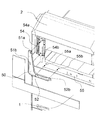
図3に示すように、連結部材50は垂直方向と水平方向に延伸するL字型の板状部を基本形状とし、そのL字型の板状部に4本の位置決めピン51a、51b、52a、52bが設けられている。一方、図1に示すように、マウントフレーム5の左側面54には、位置決めピン51a、51bに対応する凹部54a、54bが設けられており、またプリンタ本体1の構造体の左側面55には、位置決めピン52a、52bに対応する凹部55a、55bが設けられている。
As shown in FIG. 3, the connecting
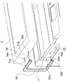
連結部材50は、離間角部8と支持角部7を含む装置左側面に垂直な方向に着脱可能である。原稿読取ユニットを取り付ける際は、マウントフレーム5をプリンタ本体1上に載置した後、位置決めピンと凹部とをそれぞれ位置合わせして、連結部材50を装置左側面と垂直な方向に押し嵌める。これにより、位置決めピン51a、51bによりマウントフレーム5と連結部材50が位置決め締結され、また位置決めピン52a、52bによりプリンタ本体1と連結部材50が位置決め締結されて、マウントフレーム5とプリンタ本体1との連結固定が図られる。逆に原稿読取ユニットを取り外す際は、装置左側面と垂直な方向に連結部材50を引き抜くことで、マウントフレーム5とプリンタ本体1との連結が解除される。
The connecting
なお、連結部材50の形状は、シート排出用空間の開放部分から退避した形状(開放部分との重なりを回避した形状)となっているため、連結部材50によりシート排出用空間へのアクセス性が損なわれることはない。
Note that the shape of the connecting
原稿読取ユニットの左端は支持角部7による片持ち支持ゆえ、離間角部8に垂直荷重が作用した場合、支持角部7では装置左側面に平行な面内の回転モーメントが発生する。しかし、本実施形態の構成によれば、位置決めピン51a、51bにより、装置左側面に平行な面内におけるマウントフレーム5と連結部材50の相対移動(相対回転)が規制されるとともに、位置決めピン52a、52bにより、装置左側面に平行な面内におけるプリンタ本体1と連結部材50の相対移動(相対回転)が規制されるため、原稿読取ユニットの倒れが好適に抑制される。
Since the left end of the document reading unit is cantilevered by the
また、連結部材50を介在させたことにより、垂直荷重による応力が、マウントフレーム5と連結部材50の間の第1係合部と、プリンタ本体1と連結部材50の間の第2係合部とに分散する。しかも本実施形態では、マウントフレーム5と連結部材50の間の係合が2箇所の係合部(位置決めピン51a、51b)で行われているため、各々の係合部に作用する応力が問題にならないレベルにまで抑えられる。プリンタ本体1と連結部材50との係合についても同様である。このような応力分散効果により、マウントフレーム5やプリンタ本体1に局所的に過大な力が作用することが防止されるので、結果として、原稿読取ユニットの支持剛性が向上するとともに、原稿読取精度や画像形成精度の低下が抑制される。
Further, since the connecting
なお、係合部同士の距離が大きいほど、梃子作用により、応力分散効果が高まる。よって本実施形態のように、位置決めピン51aをマウントフレーム5の脚の下端部に、位置決めピン51bを上端部に係合させることで、係合部同士の距離を確保することが好ましい。プリンタ本体側の位置決めピン52a、52bについても、プリンタ本体1の奥行きの1/3以上、好ましくは1/2以上の距離を空けて配置するとよい。さらに、係合部の
数を増やすことで応力分散効果を高めてもよい。
Note that the greater the distance between the engaging portions, the greater the stress dispersion effect due to the lever action. Therefore, as in the present embodiment, it is preferable to secure the distance between the engaging portions by engaging the
ところで、マウントフレーム5やプリンタ本体1では応力が分散するのに対し、連結部材50では応力が集中しやすくなる。例えば本実施形態のL字型の連結部材50の場合、解析上、板状部の屈曲部分(図3の符号53で示す領域)に応力のピークが現れる。本実施形態では、この応力集中を利用して、プリンタ本体1やマウントフレーム5が破損する限界応力よりも低い応力で、連結部材50が塑性変形するよう、意図的に設計している。すなわち、連結部材50の限界耐力をマウントフレーム5及びプリンタ本体1の限界耐力よりも小さく設定するのである。これにより、過大な荷重が作用した場合には、連結部材50が安全装置として機能し、連結部材50の変形により外力が吸収され、機能要素の破損が未然に防止される。また、連結部材50が変形するとマウントフレーム5が傾くので、ユーザに破損の発生を視覚的に知らせる事ができる。連結部材50が塑性変形を起こす設定応力は、連結部材の形状によって容易に調整可能である。万一、過負荷によって連結部材50が破損した場合は、部品交換により容易に修復可能である。
By the way, while the stress is dispersed in the
本実施形態の連結部材50は、以上のような強度メリットを有しつつ、構成は非常にシンプルであるため低コストである。また、取付作業も容易なことから、破損交換や、市場でのイメージスキャナのオプション設置にも簡単に対応できる。
The connecting
(変形例)
上記実施形態は本発明の一具体例を例示したものにすぎない。本発明の範囲は上記実施形態に限られるものではなく、その技術思想の範囲内で種々の変形が可能である。
(Modification)
The above embodiment is merely an example of the present invention. The scope of the present invention is not limited to the above embodiment, and various modifications can be made within the scope of the technical idea.
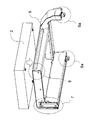
例えば、上記実施形態では、マウントフレーム5の上にイメージスキャナ2を載せるタイプの構成に対して本発明を適用した。しかし、本発明は、イメージスキャナ2をプリンタ本体1へ連結固定する構成に対しても同様に適用できる。図4の例では、C字型の連結部材56を介して、イメージスキャナ2とプリンタ本体1とを連結している。
For example, in the above embodiment, the present invention is applied to a configuration in which the
また、上記実施形態では3点支持の原稿読取ユニットを例示したが、本発明は2点支持の場合にも適用可能である。また、上記実施形態では左前の角部が離間している例を挙げたが、離間角部を設ける位置はこれに限らず、例えば右前の角部を離間角部としてもよい。また、連結部材を適用する角部は、離間角部の隣にある支持角部であればよく、図5の画像形成装置でいえば、左奥の角部だけでなく、右前の角部にも適用可能である。連結部材を複数箇所に適用すれば、1箇所のみへの適用よりも更に大きな効果が得られる。 In the above embodiment, a three-point supported document reading unit is illustrated, but the present invention can also be applied to a two-point supported case. Moreover, although the example which left front corner | angular part spaced apart was given in the said embodiment, the position which provides a separation | spacing corner part is not restricted to this, For example, it is good also considering a corner part on the right front as a separation | spacing corner part. Further, the corner portion to which the connecting member is applied may be a support corner portion adjacent to the separation corner portion. In the image forming apparatus of FIG. 5, not only the corner portion at the left back but also the corner portion at the front right side. Is also applicable. If the connecting member is applied to a plurality of locations, a greater effect than that applied to only one location can be obtained.
連結部材の形状は、先に挙げたL字型やC字型に限らない。例えば、T字型や一直線形状の連結部材を用いてもよい。すなわち、連結部材は、離間角部と支持角部を含む装置側面に沿って延伸した形状を呈していればよい。 The shape of the connecting member is not limited to the L-shape or C-shape mentioned above. For example, a T-shaped or straight connection member may be used. In other words, the connecting member only needs to exhibit a shape that extends along the side of the device including the separation corner and the support corner.
また、係合部の構成も位置決めピンに限らない。例えば、板金エッジの挿し込みによる位置決めや、凸レールと凹レールの係合などでもよい。 Further, the configuration of the engaging portion is not limited to the positioning pin. For example, positioning by inserting a sheet metal edge or engagement between a convex rail and a concave rail may be used.
1 プリンタ本体(画像形成ユニット)
2 イメージスキャナ(原稿読取ユニット)
3 コントローラ
5 マウントフレーム(原稿読取ユニット)
6a 右前の角部
6b 右奥の角部
7 左奥の角部(支持角部)
8 左前の角部(離間角部)
10 レーザースキャナ
11 プロセスカートリッジ
12 感光ドラム
13 帯電器
14 現像器
15 トナーカートリッジ
16 中間転写ベルト
17 2次転写ローラ
18 クリーナ
19 一次転写ローラ
20 定着器
22 排出ローラ
23 胴内排紙トレイ
30 給紙部
36 縦搬送パス
40 レジストローラ対
50 連結部材
51a、51b 位置決めピン(第1係合部)
52a、52b 位置決めピン(第2係合部)
53 応力集中が起こる領域
54a、54b、55a、55b 凹部
54 マウントフレームの左側面
55 プリンタ本体の左側面
56 連結部材
1 Printer body (image forming unit)
2 Image scanner (original reading unit)
3
6a Front right corner 6b Back
8 Front left corner (separating corner)
DESCRIPTION OF
52a, 52b Positioning pin (second engaging part)
53 Area where stress concentration occurs 54a, 54b, 55a,
Claims (7)
前記原稿読取ユニットの複数の角部のうち少なくとも1つの角部は、前記画像形成ユニットから離間した離間角部であり、
前記離間角部を挟む2つの装置側面では、前記シート排出用空間が装置外部に開放されており、
前記離間角部の隣の角部であって前記画像形成ユニットに支持される支持角部では、前記原稿読取ユニットが前記画像形成ユニットに連結部材を介して間接的に連結されていることを特徴とする画像形成装置。 In an image forming apparatus in which a document reading unit is supported above an image forming unit and a sheet discharge space is formed between the document reading unit and the image forming unit.
At least one corner portion of the plurality of corner portions of the document reading unit is a separated corner portion separated from the image forming unit,
The sheet discharge space is open to the outside of the apparatus on the two apparatus side surfaces sandwiching the separation angle portion,
The document reading unit is indirectly connected to the image forming unit via a connecting member at a corner that is adjacent to the separation corner and is supported by the image forming unit. An image forming apparatus.
前記原稿読取ユニットの側面に係合する第1係合部と、
前記画像形成ユニットの側面に係合する第2係合部と、を有する
ことを特徴とする請求項1に記載の画像形成装置。 The connecting member is
A first engaging portion that engages with a side surface of the document reading unit;
The image forming apparatus according to claim 1, further comprising a second engaging portion that engages with a side surface of the image forming unit.
ことを特徴とする請求項2に記載の画像形成装置。 The image forming apparatus according to claim 2, wherein each of the first engagement portion and the second engagement portion includes a plurality of engagement portions.
前記第1係合部により、前記離間角部と前記支持角部を含む装置側面に平行な面内における前記原稿読取ユニットと前記連結部材の相対移動を規制し、
前記第2係合部により、前記離間角部と前記支持角部を含む装置側面に平行な面内における前記画像形成ユニットと前記連結部材の相対移動を規制する
ことを特徴とする請求項2または3に記載の画像形成装置。 The connecting member is
The first engagement portion regulates relative movement of the document reading unit and the connecting member in a plane parallel to the side surface of the apparatus including the separation angle portion and the support corner portion,
3. The relative movement of the image forming unit and the connecting member in a plane parallel to a side surface of the apparatus including the separation angle portion and the support corner portion is regulated by the second engagement portion. The image forming apparatus according to 3.
ことを特徴とする請求項1〜4のいずれかに記載の画像形成装置。 The image forming apparatus according to claim 1, wherein the connecting member is detachable in a direction perpendicular to a side surface of the apparatus including the separation corner and the support corner.
ことを特徴とする請求項1〜5のいずれかに記載の画像形成装置。 6. The image according to claim 1, wherein the connecting member has a shape retracted from an open portion of the sheet discharge space on the side surface of the apparatus including the separation corner and the support corner. Forming equipment.
ことを特徴とする請求項1〜6のいずれかに記載の画像形成装置。 The image forming apparatus according to claim 1, wherein a limit proof stress of the connecting member is smaller than a limit proof strength of the document reading unit and the image forming unit.
Priority Applications (1)
| Application Number | Priority Date | Filing Date | Title |
|---|---|---|---|
| JP2004348869A JP2006154662A (en) | 2004-12-01 | 2004-12-01 | Image forming apparatus |
Applications Claiming Priority (1)
| Application Number | Priority Date | Filing Date | Title |
|---|---|---|---|
| JP2004348869A JP2006154662A (en) | 2004-12-01 | 2004-12-01 | Image forming apparatus |
Publications (2)
| Publication Number | Publication Date |
|---|---|
| JP2006154662A true JP2006154662A (en) | 2006-06-15 |
| JP2006154662A5 JP2006154662A5 (en) | 2009-10-15 |
Family
ID=36633017
Family Applications (1)
| Application Number | Title | Priority Date | Filing Date |
|---|---|---|---|
| JP2004348869A Pending JP2006154662A (en) | 2004-12-01 | 2004-12-01 | Image forming apparatus |
Country Status (1)
| Country | Link |
|---|---|
| JP (1) | JP2006154662A (en) |
Cited By (5)
| Publication number | Priority date | Publication date | Assignee | Title |
|---|---|---|---|---|
| JP2013003359A (en) * | 2011-06-16 | 2013-01-07 | Konica Minolta Business Technologies Inc | Image forming apparatus |
| JP2013109204A (en) * | 2011-11-22 | 2013-06-06 | Brother Ind Ltd | Image forming apparatus |
| JP2014235267A (en) * | 2013-05-31 | 2014-12-15 | 株式会社リコー | Image forming apparatus |
| JP2017198830A (en) * | 2016-04-27 | 2017-11-02 | 京セラドキュメントソリューションズ株式会社 | Image forming apparatus |
| JP2020170032A (en) * | 2019-04-01 | 2020-10-15 | ブラザー工業株式会社 | Image forming device |
Citations (4)
| Publication number | Priority date | Publication date | Assignee | Title |
|---|---|---|---|---|
| JPH10280527A (en) * | 1997-03-31 | 1998-10-20 | Natl House Ind Co Ltd | Structure of strength wall |
| JP2002202644A (en) * | 2000-12-28 | 2002-07-19 | Ricoh Co Ltd | Image forming device |
| JP2002249078A (en) * | 2001-02-26 | 2002-09-03 | Aisin Seiki Co Ltd | Shock absorbing structure for vehicle |
| JP2003209647A (en) * | 2002-01-15 | 2003-07-25 | Canon Inc | Image forming apparatus |
-
2004
- 2004-12-01 JP JP2004348869A patent/JP2006154662A/en active Pending
Patent Citations (4)
| Publication number | Priority date | Publication date | Assignee | Title |
|---|---|---|---|---|
| JPH10280527A (en) * | 1997-03-31 | 1998-10-20 | Natl House Ind Co Ltd | Structure of strength wall |
| JP2002202644A (en) * | 2000-12-28 | 2002-07-19 | Ricoh Co Ltd | Image forming device |
| JP2002249078A (en) * | 2001-02-26 | 2002-09-03 | Aisin Seiki Co Ltd | Shock absorbing structure for vehicle |
| JP2003209647A (en) * | 2002-01-15 | 2003-07-25 | Canon Inc | Image forming apparatus |
Cited By (6)
| Publication number | Priority date | Publication date | Assignee | Title |
|---|---|---|---|---|
| JP2013003359A (en) * | 2011-06-16 | 2013-01-07 | Konica Minolta Business Technologies Inc | Image forming apparatus |
| JP2013109204A (en) * | 2011-11-22 | 2013-06-06 | Brother Ind Ltd | Image forming apparatus |
| JP2014235267A (en) * | 2013-05-31 | 2014-12-15 | 株式会社リコー | Image forming apparatus |
| JP2017198830A (en) * | 2016-04-27 | 2017-11-02 | 京セラドキュメントソリューションズ株式会社 | Image forming apparatus |
| JP2020170032A (en) * | 2019-04-01 | 2020-10-15 | ブラザー工業株式会社 | Image forming device |
| JP7338207B2 (en) | 2019-04-01 | 2023-09-05 | ブラザー工業株式会社 | image forming device |
Similar Documents
| Publication | Publication Date | Title |
|---|---|---|
| US8472836B2 (en) | Cover opening/closing unit and image forming apparatus | |
| JP5414171B2 (en) | Image forming apparatus | |
| KR100828761B1 (en) | Image forming apparatus | |
| US8971756B2 (en) | Image forming apparatus and connecting method | |
| US8588645B2 (en) | Multi-function printer | |
| JP2006154662A (en) | Image forming apparatus | |
| JP4298363B2 (en) | Image forming apparatus | |
| KR101440016B1 (en) | Image forming apparatus | |
| US20160231695A1 (en) | Image Forming Apparatus Provided with Process Cartridge | |
| JP4077335B2 (en) | Image forming apparatus | |
| US9785107B2 (en) | Frame including a post and a stay and image forming apparatus including said frame | |
| JP5577835B2 (en) | Image forming apparatus | |
| US20120237257A1 (en) | Color image forming apparatus | |
| JP2014235267A (en) | Image forming apparatus | |
| JP4298669B2 (en) | Image forming apparatus | |
| JP5316109B2 (en) | Image forming apparatus | |
| JP2006171534A (en) | Image forming apparatus | |
| JP2008058342A (en) | Image forming apparatus | |
| JP2006349850A (en) | Image forming apparatus | |
| JP2007155880A (en) | Image forming apparatus | |
| JP2004325904A (en) | Image forming apparatus | |
| JP5032078B2 (en) | Image forming apparatus | |
| JP2023080719A (en) | Image formation device | |
| US20140169841A1 (en) | Image forming apparatus | |
| JP2023064206A (en) | Image forming apparatus |
Legal Events
| Date | Code | Title | Description |
|---|---|---|---|
| A521 | Written amendment |
Free format text: JAPANESE INTERMEDIATE CODE: A523 Effective date: 20071129 |
|
| A621 | Written request for application examination |
Free format text: JAPANESE INTERMEDIATE CODE: A621 Effective date: 20071129 |
|
| A521 | Written amendment |
Free format text: JAPANESE INTERMEDIATE CODE: A523 Effective date: 20090901 |
|
| A977 | Report on retrieval |
Free format text: JAPANESE INTERMEDIATE CODE: A971007 Effective date: 20100806 |
|
| A131 | Notification of reasons for refusal |
Free format text: JAPANESE INTERMEDIATE CODE: A131 Effective date: 20100810 |
|
| A521 | Written amendment |
Free format text: JAPANESE INTERMEDIATE CODE: A523 Effective date: 20101012 |
|
| A131 | Notification of reasons for refusal |
Free format text: JAPANESE INTERMEDIATE CODE: A131 Effective date: 20101214 |
|
| A02 | Decision of refusal |
Free format text: JAPANESE INTERMEDIATE CODE: A02 Effective date: 20110405 |