JP2006149986A - Cushioning body - Google Patents
Cushioning body Download PDFInfo
- Publication number
- JP2006149986A JP2006149986A JP2004349198A JP2004349198A JP2006149986A JP 2006149986 A JP2006149986 A JP 2006149986A JP 2004349198 A JP2004349198 A JP 2004349198A JP 2004349198 A JP2004349198 A JP 2004349198A JP 2006149986 A JP2006149986 A JP 2006149986A
- Authority
- JP
- Japan
- Prior art keywords
- cushion
- seal portion
- gas
- air
- cushion body
- Prior art date
- Legal status (The legal status is an assumption and is not a legal conclusion. Google has not performed a legal analysis and makes no representation as to the accuracy of the status listed.)
- Granted
Links
Images


Abstract
Description
本発明は、座布団、枕、寝具用マットレス(ベッド用マットレスおよび布団タイプのマットレス)、ソファー用マットレス、クッション、車椅子を含む椅子の座部、ヘッドレスト、緩衝材、防音材、断熱材等として使用するに好適なクッション体に関する。 The present invention is used as a cushion, a pillow, a mattress for bedding (a mattress for a bed and a mattress), a sofa mattress, a cushion, a chair seat including a wheelchair, a headrest, a cushioning material, a soundproofing material, a heat insulating material, and the like. It is related with the cushion body suitable for.
この種のクッション体として、従来より、内部に空気を封入したものが知られているが、このような空気封入タイプのクッション体の中には、(a)大きな1つの空気室のみを備えているものと、(b)多数の空気室がベース材に支持されており、かつこれら多数の空気室が互いに連通されているもの(例えば、特許文献1および2参照)があった。
As this type of cushion body, there has conventionally been known one in which air is sealed inside. However, in such an air-filled type cushion body, (a) only one large air chamber is provided. And (b) many air chambers are supported by the base material, and these many air chambers communicate with each other (for example, see
しかし、前記(a)の大きな1つの空気室のみを備えているものは、人体等の支持対象物が非常に不安定に支持され、安定性がよくないという問題があった。また、所謂底付きを生じ易いという問題もあった。 However, the apparatus having only one large air chamber (a) has a problem that a support object such as a human body is supported very unstable and stability is not good. There is also a problem that so-called bottoming is likely to occur.
他方、前記(b)の互いに連通された多数の空気室を有するクッション体においては、多数の空気室を有することにより、上記問題を改善できる。また、各空気室は互いに連通されているので、それらがそれぞれ受ける変形の多少に関わらず同じ圧力になるため、広い領域において均一な圧力分布とすることができるから、使用者の体の一部にのみ局部的に大きな圧力が持続的に作用し、使用者の皮膚や筋肉組織を破壊する等の障害(例えば、寝たきり高齢者等に生じる床ずれがその一例である)を生じさせる虞を防止できる。
しかしながら、特許文献1および2等に開示されている、多数の空気室がベース材に支持されており、かつこれら多数の空気室が互いに連通されているクッション体は、縦横に格子状に設けられた連通路を介して各空気室が互いに連通される構成となっていたので、空気室および連通路の構造が複雑となり、製造コストが高くなるとともに比較的に重量が重くなるという問題があった。
However, the cushion body disclosed in
本発明は、このような従来の事情に鑑みてなされたもので、本発明の目的は、互いに連通された複数の空気室を備え、なおかつ構造を非常に簡単にすることができるクッション体を提供することにある。 The present invention has been made in view of such conventional circumstances, and an object of the present invention is to provide a cushion body that includes a plurality of air chambers that are in communication with each other and that can be very simple in structure. There is to do.
本発明の他の目的は、製造コストを非常に安価にすることができるクッション体を提供することにある。 Another object of the present invention is to provide a cushion body that can be manufactured at a very low cost.
本発明の他の目的は、軽量とすることできるクッション体を提供することにある。 Another object of the present invention is to provide a cushion body that can be reduced in weight.
本発明のさらに他の目的は、以下の説明から明らかになろう。 Still other objects of the present invention will become apparent from the following description.
本発明によるクッション体は、少なくとも1個のクッションユニットを有してなり、
前記クッションユニットは、それぞれ膜状体に囲まれてなる3個以上の気体室と、これらの気体室に取り囲まれる位置に設けられ、各気体室を互いに連通する連通口とを有するものである。
The cushion body according to the present invention comprises at least one cushion unit,
The cushion unit includes three or more gas chambers each surrounded by a film-like body, and a communication port that is provided at a position surrounded by the gas chambers and communicates with each other.
本発明のクッション体においては、気体室に空気等の気体を適量充填した状態とすると、外部から人体等に押圧された場合、押圧されることによって他の気体室より圧力が高くなった気体室の気体の一部が連通口を通って圧力の低い他の気体室へ押し出されて行く。この際、連通口は流体抵抗となり、高圧の気体室から低圧の気体室への気体の移動を急激ではなく、比較的に緩やかに行われるようにする。これより、ある時間経過後に、最終的には各クッションユニットの全ての気体室の圧力が等しくなる。 In the cushion body of the present invention, when the gas chamber is filled with an appropriate amount of gas such as air, the gas chamber whose pressure is higher than the other gas chambers when pressed against the human body or the like from the outside. A part of the gas passes through the communication port and is pushed out to another gas chamber having a low pressure. At this time, the communication port becomes a fluid resistance, and the movement of the gas from the high-pressure gas chamber to the low-pressure gas chamber is performed not slowly but relatively slowly. Thus, after a certain period of time, the pressures of all the gas chambers of each cushion unit are finally equalized.
したがって、外部から人体等に押圧された部分は比較的緩やかに押し下げられて行く一方、その近傍の部分は比較的緩やかに膨張してクッション体側から人体等を押圧するようになるので、人体等がクッション体の広い領域で支持される。そして、連通口を通して気体室間を気体が流通している過程では、各クッションユニットの気体室間に多少の圧力差が存在しているものの、最終的には各気体室は同じ圧力となるので、人体等がクッション体の広い領域で均一な圧力で支持される。これ故、使用者の体の一部にのみ局部的に大きな圧力が持続的に作用し、使用者の皮膚や筋肉組織を破壊する等の障害の発生を防止できる。 Therefore, the portion pressed against the human body etc. from the outside is pushed down relatively gently, while the portion in the vicinity thereof expands relatively gently and presses the human body etc. from the cushion body side. It is supported in a wide area of the cushion body. In the process of gas flowing between the gas chambers through the communication port, although there is a slight pressure difference between the gas chambers of each cushion unit, each gas chamber eventually has the same pressure. The human body is supported with a uniform pressure over a wide area of the cushion body. Therefore, a large local pressure is continuously applied only to a part of the user's body, and the occurrence of a disorder such as destruction of the user's skin and muscle tissue can be prevented.
また、外部から人体に押圧された場合、各部が急速に凹んだり、膨らんだりするのではなく、前述のように、押圧された部分は比較的緩やかに押し下げられて行く一方、その近傍の部分は比較的緩やかに膨張するので、使用者に非常に心地よい感触を与える。また、衝撃的な荷重が作用しても、それを吸収することができる。 In addition, when pressed by the human body from the outside, each part does not rapidly dent or swell, but as described above, the pressed part is pushed down relatively gently, while the part near it is Since it swells relatively slowly, it gives the user a very pleasant feel. Moreover, even if an impact load acts, it can be absorbed.
また、複数の気体室を有しているので、人体等が安定に支持されるようにすることができるとともに、底付きを生じ難くすることができる。 Moreover, since it has several gas chambers, while being able to support a human body etc. stably, it can make it difficult to produce bottoming.
また、各気体室に取り囲まれる位置に各気体室を互いに連通する連通口を設けることにより、各クッションユニットを構成できるので、構造を非常に簡単にすることができる。そして、これにより、製造コストを極めて安価とすることができるとともに、極めて軽量とすることができる。 Moreover, since each cushion unit can be comprised by providing the communication port which mutually connects each gas chamber in the position enclosed by each gas chamber, a structure can be simplified very much. As a result, the manufacturing cost can be extremely low and the weight can be extremely light.
また、気体室内への空気等の気体の充填量を調整することにより、クッション体の固さを調整することもできる。 Further, the hardness of the cushion body can be adjusted by adjusting the filling amount of gas such as air into the gas chamber.
また、本発明の一つの態様においては、1つのクッション体が複数のクッションユニットを備える。この態様によれば、広面積のクッション体を構成することができ、かつ各クッションユニットの気体室内への気体の充填量を変えることにより、クッション体の固さを部位によって異なるようにすることも可能となる。 Moreover, in one aspect of the present invention, one cushion body includes a plurality of cushion units. According to this aspect, a cushion body having a large area can be configured, and the hardness of the cushion body can be made different depending on the region by changing the gas filling amount into the gas chamber of each cushion unit. It becomes possible.
本発明のクッション体においては、
(イ)構造を非常に簡単にすることができる、
(ロ)製造コストを極めて安価とすることができる、
(ハ)極めて軽量とすることができる、
(ニ)クッションユニットを複数備えさせ、かつ各クッションユニットの気体室内への気体の充填量を変えることにより、クッション体の固さを部位によって異なるようにすることができる、
等の優れた効果を得ることができる。
In the cushion body of the present invention,
(I) The structure can be made very simple.
(B) The manufacturing cost can be extremely low.
(C) It can be extremely lightweight,
(D) By providing a plurality of cushion units and changing the amount of gas filled into the gas chamber of each cushion unit, the hardness of the cushion body can be made different depending on the part.
Such excellent effects can be obtained.
以下、本発明を図面に示す実施例に基づいて説明する。 Hereinafter, the present invention will be described based on embodiments shown in the drawings.
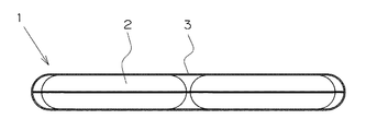
図1〜6は本発明の実施例1を示しており、このうち図1〜5は、本実施例のクッション体1(図6参照)におけるクッションユニット2を、後で詳しく説明する外皮3(図6参照)から取り出した状態を示している。前記クッションユニット2は、熱可塑性ポリウレタン樹脂、EVA、スチレン系エラスマー、オレフィン系エラストマー等の熱可塑エラスマーからなり、ガスバリア性、柔軟性ないしは可撓性、および伸縮性を有する四角形状の2枚の膜状体(フィルムないしはシート)4,5を、次に説明するようにシールしてなる。
FIGS. 1-6 has shown Example 1 of this invention, Among these, FIGS. 1-5 show the outer skin 3 (it demonstrates in detail later) the
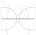
前記2枚の膜状体4,5は、 ヒートシール方式 、インパルスシール方式、高周波ンール方式または超音波シール方式等により、周辺シール部6、仕切りシール部7および補強シール部8において互いに溶着されてシールされることにより、4つの気体室9を形成されている。前記周辺シール部6は、膜状体4,5の4辺付近に、該4辺に沿って四角形状に設けられている。前記仕切りシール部7は、膜状体4,5の縦方向および横方向中央部を、膜状体4,5が平面上に保持されている状態において直線状に延びるように4本設けられており、該仕切りシール部7の外端部は周辺シール部6に連続し、内端部は膜状体4,5の中央付近に位置している。そして、これらの仕切りシール部7により各気体室9は互いに仕切られている。前記補強シール部8は、環状をなしていて、4本の仕切りシール部7の内端部間に設けられている。前記4本の仕切りシール部7の内端部と補強シール部8との間に設けられた非シール部分は1組の連通口11を形成しており(本実施例では、4本の仕切りシール部7の内端部と補強シール部8との間の4箇所に非シール部分が存在することとなるが、機能的にはこれらは1つの連通口11と考えることができる)、各気体室9を互いに共通に連通している。したがって、それぞれ四角形状をなす4つの気体室9が、それらの1つの角部が互いに接する部分において連通口11を介して互いに連通されている。言い換えれば、連通口11は各気体室9に取り囲まれる位置に設けられて、各気体室9を互いに連通している。前記仕切りシール部7の内端部と補強シール部8との間の距離は、4〜8mm程度が好ましい。なお、図4および5の断面図は、仕切りシール部7および補強シール部8を模式的に示しており、必ずしも実際のシール部を忠実に描いたものではないことに留意されたい。
The two film-
前記気体室9の1つには、従来公知の、逆止弁を内蔵した軟質プラスチックからなる気体注入・排出口12が設けられており、この気体注入・排出口12は一体に設けられた栓12aにより開閉できるようになっている。
One of the
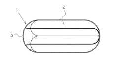
図6は、本実施例のクッション体1全体を示しており、全体を袋状とされた外皮3内に1つのクッションユニット2を収容してなる(したがって、本実施例においては、クッション体1は1つのクッションユニット2のみを備えている)。前記外皮3は、布、プラスチックフィルムないしはシート等の柔軟な膜状体4,5からなる。なお、前記外皮3は、それ自体が密閉された空気室を構成してクッション体1の特性を阻害することとならないように、その素材自体が通気性を備えているか、通気孔を設けられていることが好ましい。
FIG. 6 shows the entirety of the
このクッション体1においては、気体注入・排出口12から該気体注入・排出口12が設けられている気体室9に空気を注入すると、連通口11を通って他の気体室9にも空気が注入されて行く。
In this
ここにおいて、このクッション体1のように連通口11を介して各気体室9が共通に(同時に)連通されているのではなく、複数の気体室9が直列に連通されていると、1つの気体室9に外部から気体を注入することにより、全体の気体室9に気体を注入しようとする場合、最初の気体室9に空気を注入し始めてから末端の気体室9にまで空気が行き渡るまでの時間が許容できない程長くなってしまう虞があるが、このクッション体1においてはそのような虞はない。
Here, the
前記のように空気を注入して、各気体室9に空気を適量充填した状態とすると、外部から人体等に押圧された場合、押圧されることによって他の気体室9より圧力が高くなった気体室9の空気の一部が連通口11を通って圧力の低い他の気体室9へ押し出されて行く。この際、連通口11は流体(空気)抵抗となり、高圧の気体室9から低圧の気体室9への空気の移動が急激ではなく、比較的に緩やかに行われるようにする。これより、ある時間経過後に、最終的には全ての気体室9の圧力が等しくなる。
When air was injected as described above and each
したがって、外部から人体等に押圧された部分は比較的緩やかに押し下げられて行く一方、その近傍の部分は比較的緩やかに膨張してクッション体1側から人体等を押圧するようになるので、人体等がクッション体1の広い領域で支持される。そして、空気が連通口11を通して気体室9間を流通している過程では、気体室9間に多少の圧力差が存在しているものの、最終的には各気体室9は同じ圧力となるので、人体等がクッション体1の広い領域で均一な圧力で支持される。これ故、使用者の体の一部にのみ局部的に大きな圧力が持続的に作用し、使用者の皮膚や筋肉組織を破壊する等の障害の発生を防止できる。
Accordingly, the portion pressed against the human body or the like from the outside is pushed down relatively gently, while the portion in the vicinity thereof expands relatively gently and presses the human body or the like from the
また、外部から人体に押圧された場合、各部が急速に凹んだり、膨らんだりするのではなく、前述のように、押圧された部分は比較的緩やかに押し下げられて行く一方、その近傍の部分は比較的緩やかに膨張するので、使用者に非常に心地よい感触を与える。また、衝撃的な荷重が作用しても、それを吸収することができる。 In addition, when pressed by the human body from the outside, each part does not rapidly dent or swell, but as described above, the pressed part is pushed down relatively gently, while the part near it is Since it swells relatively slowly, it gives the user a very pleasant feel. Moreover, even if an impact load acts, it can be absorbed.
また、複数の気体室9を有しているので、人体等が安定に支持されるようにすることができるとともに、底付きを生じ難くすることができる。
Moreover, since it has the
また、各気体室9に取り囲まれる位置に各気体室9を互いに連通する連通口11を設けることにより、クッションユニット2を構成できるので、構造を非常に簡単にすることができる。そして、これにより、製造コストを極めて安価とすることができるとともに、極めて軽量とすることができる。
In addition, the
また、気体注入・排出口12からの気体室9内への空気の充填量を調整することにより、クッション体1の固さを調整することもできる。
Further, the hardness of the
また、本実施例においては、補強シール部8が設けられているので、仕切りシール部7の内端部に集中荷重が作用して該部分が破損する虞を防止することができる。ただし、補強シール部8は必ずしも環状ではなく、多角形状等の他の閉じられた形状をなしていてもよいし、閉じられてない形状としてもよいし、場合によっては補強シール部8は設けなくてもよい。
Further, in this embodiment, since the reinforcing
図7および8は、本発明の実施例2を示している。本実施例においては、袋状の外皮3内に実施例1のクッションユニット2が複数収容されている。前記外皮3の相対向する面(表面と裏面)間には、布、プラスチックフィルムないしはシート等の柔軟な膜状体からなる仕切り膜13が設けられており、これらの仕切り膜13は外皮3内における各クッションユニット2の移動を制限するとともに、外皮3の相対向する面が一定以上離間しないように規制している。他の構成は前記実施例1と同様である。
7 and 8 show Example 2 of the present invention. In the present embodiment, a plurality of
本実施例においては、クッションユニット2を複数備えることにより、広面積のクッション体1を構成することができる。また、各クッションユニット2の気体室9内への空気の充填量を変えることにより、例えば大きな力が作用すると予定される部分は固くする一方、大きな力が作用すると予定されない部分は柔らかくと言うように、クッション体1の固さをクッション体1の部位によって異なるようにすることも可能となる。
In the present embodiment, the
なお、仕切り膜13は必ずしも設けなくてもよいが、設ければ、外皮3内においてクッションユニット2が過度に動き、望ましい位置から逸脱してしまう虞を防止できる。
The
前記図1〜5の実施例1においては、場合によっては、外部から圧力を作用されても、図9に示されるように、連通口11を形成する非シール部の膜状体4,5の内面同士が互いに貼り付いて密着したまま、したがって連通口11が閉じたままとなり、気体室9間で空気の流通が行われないことがある一方、力の作用状態によっては、突然、非シール部11の膜状体4,5の内面同士が大きく離れ、したがって連通口11が大きく開き、突然気体室9間で空気の流通が大きく行われるようになったりして、動作が不安定になる虞がある。
In the first embodiment of FIGS. 1 to 5, depending on the case, even if pressure is applied from the outside, as shown in FIG. While the inner surfaces are stuck to each other and are in close contact with each other, the
図10は、このような不都合を防止することができる本発明の実施例3を示している。本実施例においては、連通口11を形成する非シール部の膜状体4,5の内面にそれぞれ凹凸14,15が設けられている。他の構成は実施例1と同様である。
FIG. 10 shows a third embodiment of the present invention that can prevent such an inconvenience. In this embodiment,
本実施例においては、凹凸14,15により、膜状体4,5の内面同士が互いに貼り付いて密着し、連通口11が閉じたままとなるのを防止し、ひいては気体室9間の空気移動動作が安定に行われるようにすることができる。
In this embodiment, the inner surfaces of the film-
なお、本実施例では、凹凸14,15は、直線状の突条と溝が交互に設けられた形状をそれぞれなしており、凹凸14の突条および溝と凹凸15の突条および溝とは互いに垂直方向に延びるようにされている。ただし、凹凸14,15は他の適当な形状としてもよい。また、凹凸を設ける代わりに、膜状体4,5の内面に粗面処理を施してもよい。また、膜状体4,5の両方ではなく、片方の膜状体の内面にのみ凹凸を設けたり、粗面処理を施してもよい。さらに、凹凸や粗面処理は、連通口11を形成する非シール部のみではなく、予め膜状体4,5の内面の全面に設けたり、施しておいてもよい。
In the present embodiment, the projections and recesses 15 and 15 have shapes in which straight projections and grooves are alternately provided, and the projections and grooves of the projections and
図11および12は、本発明の実施例4を示している。本実施例においては、仕切りシール部7の端部と補強シール部8との間の非シール部分に、Oリングからなる貼り付き防止体16が、補強シール部8を取り囲むようにして挿入されている。前記貼り付き防止体16は、膜状体4,5に対し固定はされていない。
11 and 12 show Example 4 of the present invention. In this embodiment, an
本実施例においては、連通口11を形成する非シール部に貼り付き防止体16が挿入されることにより、膜状体4,5の内面同士の貼り付きをより確実に防止し、気体室9間の空気移動動作が安定に行われるようにすることができる。
In the present embodiment, the sticking
なお、貼り付き防止体16は、必ずしもOリングでなくてもよい。また、貼り付き防止体16の構成材料は、必ずしもゴムでなくてもよく、フェルト、プラスチック、エラストマー、金属等の他の種の材料から構成されていてもよい。ただし、柔軟な材料からなることが好ましい。
In addition, the sticking
また、貼り付き防止体16は環状のみならず、他の形状であってもよい。ただし、環状、多角形状、三角形状、楕円形状等の、内部に空間が形成された閉じられた形状とし、補強シール部8を取り囲むようにすると、クッション体の製造が容易になるとともに連通口11に対し貼り付き防止体16の存在範囲を確実に位置決めできる。
Further, the sticking
また、貼り付き防止体16は、膜状体4,5のいずれか一方または両方に固定されていてもよい。
Further, the sticking
図13は、本発明の実施例5を示している。前記各実施例においては、1つのクッションユニット2が1組の連通口11のみを有していたが、本実施例においては、1つのクッションユニット2が複数組の連通口11を有しており、これらの連通口11が、互いに組み合わせが異なる4個の気体室9をそれぞれ互いに連通している。次に、これを詳しく説明する。
FIG. 13 shows a fifth embodiment of the present invention. In each of the above embodiments, one
クッションユニット2は、2枚の膜状体4,5を、周辺シール部6、仕切りシール部7および補強シール部8において互いに溶着されてシールされることにより、四角形状の16個の気体室9を形成されている。各気体室9は、仕切りシール部7によって互いに仕切られている。また、それぞれ4つの気体室9の角部が互いに接する部分毎に、1つの補強シール部8および1組の連通口11が設けられており、該連通口11を介して該連通口11を取り囲む4つの気体室9が互いに連通されている。したがって、本実施例においては、1個のクッションユニット2が、互いに組み合わせが異なる4つの気体室9をそれぞれ互いに連通する連通口11を9組有している。そして、すべての気体室9が9組の連通口11を介して互いに連通されている。前記気体室9の1つには、気体注入・排出口12が設けられている。
The
本実施例においては、1つのクッションユニット2の気体室9の数を多くすることができる。ただし、気体注入・排出口12を設けられた気体室9に対して、他の気体室9を介して間接的に連通される気体室9が存在するので、気体注入・排出口12より空気を注入し始めてから末端の気体室9にまで空気が行き渡るまでの時間は長くなる。
In the present embodiment, the number of
図14は、本発明の実施例6を示している。本実施例においては、1つの実施例1のクッションユニット2を2つ折りにした状態で外皮3内に収容することにより、枕等として使用するに好適なクッション体1を構成している。なお、複数のクッションユニット2を積層して外皮3内に収容してもよい。
前記各実施例においては、仕切りシール部7により各気体室9を仕切っているが、本発明においては、シール以外の手段により各気体室9を仕切ってもよい。
FIG. 14 shows a sixth embodiment of the present invention. In the present embodiment, the
In each of the above embodiments, each
また、前記各実施例においては、仕切りシール部7と補強シール部8との間の非シール部により連通口11を構成しているが、本発明においては、別の手段、例えば、2枚の膜状体4,5のシール部7,8に相当する部分を外側から適当な挟み付け部材で互いに密着するように挟み付ける一方、非シール部に相当する部分は前記挟み付け部材で挟み付けないようにすることによって、前記非シール部に相当する部分により連通口を形成するようにしてもよい。
Further, in each of the above embodiments, the
また、各気体室9を構成する膜状体4,5としては、柔軟性ないしは可撓性を有するものであれば、前記以外の材料からなるフィルムないしはシート等の膜状体に使用可能であるし、場合によっては、伸縮性の乏しい膜状体も使用可能である。
The
また、前記各実施例おいては、1つのクッションユニット2の気体室9の数を4個または16個としているが、本発明においては、1つのクッションユニットの気体室の数は、3個以上であれば、4個または16個以外の数としてもよい。
In each of the above embodiments, the number of
また、前記各実施例においては、各気体室9は四角形状とされているが、本発明においては、各気体室9の形状を四角形状以外の形状としてもよい。
In each of the embodiments, each
また、前記各実施例においては、各気体室9が同形同大とされているが、本発明においては、各気体室9の形や大きさを異なるようにしてもよい。
In each of the above embodiments, each
また、前記各実施例においては、気体室9に空気を収容しているが、本発明においては、気体室9に空気以外の気体を収容してもよい。
Moreover, in each said Example, although the air was accommodated in the
また、本発明のクッション体は、内部に多量の空気等の気体を含むことになるので、防音作用および断熱作用を果たすため、クッション材としてのみならず、シール材、防音材、断熱材等としても使用できる。 In addition, since the cushion body of the present invention contains a large amount of gas such as air, the cushion body according to the present invention serves not only as a cushioning material but also as a sealing material, a soundproofing material, a heat insulating material, etc. in order to achieve soundproofing and heat insulation. Can also be used.
以上のように本発明によるクッション体は、座布団、枕、寝具用マットレス、ソファー用マットレス、クッション、車椅子を含む椅子の座部、ヘッドレスト、緩衝材、シール材、防音材、断熱材等として使用するに有用である。 As described above, the cushion body according to the present invention is used as a cushion, a pillow, a mattress for bedding, a mattress for sofa, a cushion, a chair seat including a wheelchair, a headrest, a cushioning material, a sealing material, a soundproofing material, a heat insulating material, and the like. Useful for.
1 クッション体
2 クッションユニット
3 外皮
4,5 膜状体
7 仕切りシール部
8 補強シール部
9 気体室
11 連通口
14,15 凹凸
16 貼り付き防止体
DESCRIPTION OF
Claims (8)
前記クッションユニットは、それぞれ膜状体に囲まれてなる3個以上の気体室と、これらの気体室に取り囲まれる位置に設けられ、各気体室を互いに連通する連通口とを有するクッション体。 Having at least one cushion unit,
The cushion unit includes three or more gas chambers each surrounded by a film-like body and a communication port provided at a position surrounded by the gas chambers and communicating with each other.
A plurality of the cushion units are provided, and at least one of the cushion units has a different hardness from the other cushion units by adjusting the amount of gas filled in the gas chamber. The cushion body according to any one of claims 1 to 7.
Priority Applications (1)
| Application Number | Priority Date | Filing Date | Title |
|---|---|---|---|
| JP2004349198A JP4718166B2 (en) | 2004-12-01 | 2004-12-01 | Cushion body |
Applications Claiming Priority (1)
| Application Number | Priority Date | Filing Date | Title |
|---|---|---|---|
| JP2004349198A JP4718166B2 (en) | 2004-12-01 | 2004-12-01 | Cushion body |
Publications (3)
| Publication Number | Publication Date |
|---|---|
| JP2006149986A true JP2006149986A (en) | 2006-06-15 |
| JP2006149986A5 JP2006149986A5 (en) | 2007-09-06 |
| JP4718166B2 JP4718166B2 (en) | 2011-07-06 |
Family
ID=36628929
Family Applications (1)
| Application Number | Title | Priority Date | Filing Date |
|---|---|---|---|
| JP2004349198A Expired - Fee Related JP4718166B2 (en) | 2004-12-01 | 2004-12-01 | Cushion body |
Country Status (1)
| Country | Link |
|---|---|
| JP (1) | JP4718166B2 (en) |
Cited By (3)
| Publication number | Priority date | Publication date | Assignee | Title |
|---|---|---|---|---|
| JP2010142598A (en) * | 2008-12-22 | 2010-07-01 | Mizuno Corp | Cushion |
| JP2011218008A (en) * | 2010-04-12 | 2011-11-04 | Finetech Co Ltd | Air cushion |
| JP2014073359A (en) * | 2012-09-11 | 2014-04-24 | Nozaki Tokushukai Hospital | Bedsore prevention device |
Citations (5)
| Publication number | Priority date | Publication date | Assignee | Title |
|---|---|---|---|---|
| JPS647853A (en) * | 1987-06-30 | 1989-01-11 | Nec Corp | Image reader |
| JPH02149265A (en) * | 1988-11-30 | 1990-06-07 | Morita Tokyo Seisakusho:Kk | Bracket for dental remedy |
| JPH0385589U (en) * | 1989-12-20 | 1991-08-29 | ||
| JPH0464275A (en) * | 1990-07-04 | 1992-02-28 | Fujitsu Ltd | Surface mounting printed wiring board and mounting method for component thereof |
| JP2000217685A (en) * | 1999-01-28 | 2000-08-08 | Shigeoka:Kk | Aqueous liquid housed bag |
Family Cites Families (3)
| Publication number | Priority date | Publication date | Assignee | Title |
|---|---|---|---|---|
| JP2527545Y2 (en) * | 1989-05-19 | 1997-03-05 | 株式会社ハイビックス | Air bag for car seat |
| JPH0546713Y2 (en) * | 1990-10-17 | 1993-12-07 | ||
| JPH0713250U (en) * | 1993-08-13 | 1995-03-07 | 滋 加藤 | Airbag mattress |
-
2004
- 2004-12-01 JP JP2004349198A patent/JP4718166B2/en not_active Expired - Fee Related
Patent Citations (5)
| Publication number | Priority date | Publication date | Assignee | Title |
|---|---|---|---|---|
| JPS647853A (en) * | 1987-06-30 | 1989-01-11 | Nec Corp | Image reader |
| JPH02149265A (en) * | 1988-11-30 | 1990-06-07 | Morita Tokyo Seisakusho:Kk | Bracket for dental remedy |
| JPH0385589U (en) * | 1989-12-20 | 1991-08-29 | ||
| JPH0464275A (en) * | 1990-07-04 | 1992-02-28 | Fujitsu Ltd | Surface mounting printed wiring board and mounting method for component thereof |
| JP2000217685A (en) * | 1999-01-28 | 2000-08-08 | Shigeoka:Kk | Aqueous liquid housed bag |
Cited By (3)
| Publication number | Priority date | Publication date | Assignee | Title |
|---|---|---|---|---|
| JP2010142598A (en) * | 2008-12-22 | 2010-07-01 | Mizuno Corp | Cushion |
| JP2011218008A (en) * | 2010-04-12 | 2011-11-04 | Finetech Co Ltd | Air cushion |
| JP2014073359A (en) * | 2012-09-11 | 2014-04-24 | Nozaki Tokushukai Hospital | Bedsore prevention device |
Also Published As
| Publication number | Publication date |
|---|---|
| JP4718166B2 (en) | 2011-07-06 |
Similar Documents
| Publication | Publication Date | Title |
|---|---|---|
| EP1986525B1 (en) | Self inflating air mattress | |
| US5590428A (en) | Air pressurized person supporting device with ventilation | |
| AU2003231124B2 (en) | Inflatable chambers fluidly connected by one way valve and method for use | |
| CA2577693C (en) | Inflatable cushion systems and method of manufacture thereof | |
| US6415467B1 (en) | Air cushion for pressure relief and control | |
| JP2014018670A (en) | Pressure sore preventing cushion | |
| US20030159218A1 (en) | Inflatable product | |
| US20130219626A1 (en) | Cushion and self-adjusting valve | |
| JP2020515363A (en) | Improved seat cushion | |
| JP2016087117A (en) | Fluid cell type mattress | |
| JP4718166B2 (en) | Cushion body | |
| WO2017043217A1 (en) | Body pressure support cushion and auxiliary cells constituting same | |
| JP4855952B2 (en) | Cushion body and manufacturing method thereof | |
| JP4429629B2 (en) | Inflatable bag having segmented structure | |
| JP2009178284A (en) | Cushion body and cushion apparatus | |
| JP2016034398A (en) | Cell for mattress and mattress using the same | |
| JP2010046306A (en) | Cushion body | |
| KR101040048B1 (en) | Cushion Device For Seat | |
| KR100422010B1 (en) | a cushion seat | |
| JP5580649B2 (en) | Air cushion | |
| JPH0215465Y2 (en) | ||
| CN210540126U (en) | Air bed | |
| JP2016209531A (en) | Body pressure support cushion and mattress using the same | |
| JP2019017729A (en) | Body pressure support cushion and its manufacturing method | |
| JP6242841B2 (en) | Air injector |
Legal Events
| Date | Code | Title | Description |
|---|---|---|---|
| A521 | Written amendment |
Free format text: JAPANESE INTERMEDIATE CODE: A523 Effective date: 20070724 |
|
| A621 | Written request for application examination |
Free format text: JAPANESE INTERMEDIATE CODE: A621 Effective date: 20070724 |
|
| A977 | Report on retrieval |
Free format text: JAPANESE INTERMEDIATE CODE: A971007 Effective date: 20100924 |
|
| A131 | Notification of reasons for refusal |
Free format text: JAPANESE INTERMEDIATE CODE: A131 Effective date: 20100929 |
|
| A521 | Written amendment |
Free format text: JAPANESE INTERMEDIATE CODE: A523 Effective date: 20101015 |
|
| A01 | Written decision to grant a patent or to grant a registration (utility model) |
Free format text: JAPANESE INTERMEDIATE CODE: A01 Effective date: 20110315 |
|
| A01 | Written decision to grant a patent or to grant a registration (utility model) |
Free format text: JAPANESE INTERMEDIATE CODE: A01 |
|
| A61 | First payment of annual fees (during grant procedure) |
Free format text: JAPANESE INTERMEDIATE CODE: A61 Effective date: 20110331 |
|
| R150 | Certificate of patent or registration of utility model |
Free format text: JAPANESE INTERMEDIATE CODE: R150 |
|
| FPAY | Renewal fee payment (event date is renewal date of database) |
Free format text: PAYMENT UNTIL: 20140408 Year of fee payment: 3 |
|
| LAPS | Cancellation because of no payment of annual fees |