JP2006141903A - Ultrasonic diagnostic apparatus - Google Patents
Ultrasonic diagnostic apparatus Download PDFInfo
- Publication number
- JP2006141903A JP2006141903A JP2004339711A JP2004339711A JP2006141903A JP 2006141903 A JP2006141903 A JP 2006141903A JP 2004339711 A JP2004339711 A JP 2004339711A JP 2004339711 A JP2004339711 A JP 2004339711A JP 2006141903 A JP2006141903 A JP 2006141903A
- Authority
- JP
- Japan
- Prior art keywords
- ultrasonic
- information
- diagnostic apparatus
- displayed
- finding information
- Prior art date
- Legal status (The legal status is an assumption and is not a legal conclusion. Google has not performed a legal analysis and makes no representation as to the accuracy of the status listed.)
- Pending
Links
Images


Abstract
Description
本発明は、超音波を利用して被検体内の診断部位について断層像を得て表示する超音波診断装置に係り、特に音声認識技術を利用して、音声入力が可能である超音波診断装置に関する。 The present invention relates to an ultrasonic diagnostic apparatus that obtains and displays a tomographic image of a diagnostic region in a subject using ultrasonic waves, and more particularly to an ultrasonic diagnostic apparatus that enables voice input using voice recognition technology. About.
従来の超音波診断装置は、被検体に当接されて使用される超音波探触子を介して、被検体に超音波を送信及び受信する超音波送受信手段と、この超音波送受信手段からの反射エコー信号を用いて運動組織を含む被検体内の断層像データを所定周期で繰り返して得る断層走査手段と、この断層走査手段によって得た時系列断層像データを表示する画像表示手段とを有して構成されている。そして、被検体内部の生体組織の構造を例えばbモード像として表示している。 A conventional ultrasonic diagnostic apparatus includes an ultrasonic transmission / reception unit that transmits and receives ultrasonic waves to a subject via an ultrasonic probe that is used in contact with the subject, and an ultrasonic transmission / reception unit from the ultrasonic transmission / reception unit. A tomographic scanning unit that obtains tomographic image data in a subject including a moving tissue using a reflected echo signal repeatedly at a predetermined period; and an image display unit that displays time-series tomographic image data obtained by the tomographic scanning unit. Configured. The structure of the living tissue inside the subject is displayed as, for example, a b-mode image.
そして、画像表示手段に表示されているbモード像を例えばビットマップ形式の画像ファイルとして記憶し、そのビットマップ形式の画像ファイルをもとに、他の診断支援システム上で例えばキーボードから所見情報を入力し、診断レポートを作成するようになっている。このように、診断レポートを作成するような診断支援システムとしては、特許文献1に記載されたようなものがある。
しかし、上述のような従来の超音波診断装置では、超音波診断装置の画面に表示された断層像を見ながらリアルタイムで所見情報を作成することができず、一旦、他の診断支援システムに例えばビットマップ形式として画像ファイルを転送した後、例えばキーボードから所見情報を入力しなければならず、診断レポートの作成に時間がかかり、検査効率の点で問題を有していた。 However, in the conventional ultrasonic diagnostic apparatus as described above, the observation information cannot be created in real time while viewing the tomographic image displayed on the screen of the ultrasonic diagnostic apparatus. After transferring the image file as a bitmap format, it is necessary to input finding information from a keyboard, for example, and it takes time to create a diagnostic report, which is problematic in terms of inspection efficiency.
本発明の目的は、上述の点に鑑み、超音波診断装置上で超音波診断装置の画面に表示された断層像を見ながら、リアルタイムで音声認識技術を手段として音声入力した所見情報を超音波診断装置の画面上に表示させ、また、超音波診断装置の画面上に表示された所見情報を、例えばテキスト形式のファイルとして記憶し、他の診断支援システムに転送することで、例えばキーボードから所見情報を入力する時間を省くことで診断レポートを作成する時間を短縮させ、検査効率を向上させることができる超音波診断装置を提供することを目的とする。 In view of the above-described points, an object of the present invention is to provide ultrasonic information on observation information that is input in voice using a voice recognition technique in real time while viewing a tomographic image displayed on the screen of the ultrasonic diagnostic apparatus on the ultrasonic diagnostic apparatus. The observation information displayed on the screen of the diagnostic apparatus and the information displayed on the screen of the ultrasonic diagnostic apparatus are stored as, for example, a text format file and transferred to another diagnostic support system. An object of the present invention is to provide an ultrasonic diagnostic apparatus capable of reducing the time for creating a diagnostic report by reducing the time for inputting information and improving the examination efficiency.
前記課題を解決するために、本発明は以下の様に構成される。
被検体に超音波を送信し、該被検体からの反射エコー信号を受信する超音波送受信手段と、該受信信号を画像処理して超音波画像を形成する手段と、前記超音波画像を表示させる表示手段とを備えた超音波診断装置において、音声を入力する入力手段と、前記入力された音声を文字情報として認識する音声認識手段を備え、前記表示手段は、該文字情報に基づいた所見情報を前記超音波画像と共に表示する。また、前記所見情報を前記超音波画像に重ならない位置に表示することによって、検査を妨げることなく断層像を見ながら、リアルタイムで所見情報を確認することができる。
In order to solve the above-described problems, the present invention is configured as follows.
Ultrasonic transmitting / receiving means for transmitting ultrasonic waves to the subject and receiving reflected echo signals from the subject, means for processing the received signals to form ultrasonic images, and displaying the ultrasonic images An ultrasonic diagnostic apparatus comprising a display means, comprising: an input means for inputting voice; and a voice recognition means for recognizing the input voice as character information, wherein the display means is finding information based on the character information. Are displayed together with the ultrasonic image. Further, by displaying the finding information at a position that does not overlap the ultrasonic image, the finding information can be confirmed in real time while viewing the tomographic image without interfering with the examination.
また、前記所見情報を前記超音波画像に対応付けて記憶させる記憶手段を備え、表示手段に表示させる。この前記超音波画像は動画像であり、該動画像に前記所見情報を対応させて前記記憶手段に記憶させる。 In addition, a storage unit that stores the finding information in association with the ultrasonic image is displayed on the display unit. The ultrasonic image is a moving image, and the finding information is associated with the moving image and stored in the storage unit.
また、音声認識技術を手段として音声入力され、超音波診断装置の画面上に表示された所見情報を例えばテキスト形式のファイルとして記憶することができるようにしたものである。これは、所見情報ファイルが超音波診断装置の画面に表示された断層像を例えばビットマップ形式のファイルとして記憶した画像ファイルと結び付くように記憶することによって、検査後でも画像ファイルをもとに容易に所見情報を得ることができる。 Further, it is possible to store the finding information that is inputted by voice using the voice recognition technique and displayed on the screen of the ultrasonic diagnostic apparatus as, for example, a text format file. This is because the observation information file is stored in such a manner that the tomographic image displayed on the screen of the ultrasonic diagnostic apparatus is linked to the image file stored as a bitmap format file, for example, so that the image file can be easily obtained even after inspection. Finding information can be obtained.
さらに、超音波診断装置の画面上に表示された所見情報を例えばテキスト形式のファイルとして記憶した所見情報ファイルを超音波診断装置上から他の診断支援システムに転送することができるようにしたものである。これは、他の診断支援システム上で診断レポートを作成する時、所見情報ファイルを読み出すことによって、例えばキーボードから所見情報を入力する時間を省くことができる。 Furthermore, an observation information file storing the observation information displayed on the screen of the ultrasonic diagnostic apparatus as, for example, a text format file can be transferred from the ultrasonic diagnostic apparatus to another diagnosis support system. is there. This can save time for inputting finding information from a keyboard, for example, by reading a finding information file when creating a diagnosis report on another diagnosis support system.
以上、本発明によれば、超音波診断装置の画面上に音声認識技術を手段として音声入力した所見情報が表示され、その所見情報を用いることにより診断レポート作成時間を短縮することができる。 As described above, according to the present invention, the finding information input by voice using the voice recognition technique is displayed on the screen of the ultrasonic diagnostic apparatus, and the diagnosis report creation time can be shortened by using the finding information.
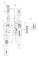
以下、本発明の実施の形態を添付図面に基づいて詳細に説明する。図1は、本発明による超音波診断装置の実施の形態を示すブロック図である。この超音波診断装置は、超音波を利用して被検体の撮影部位に関する断層像を取得して表示すると共に音声認識技術を手段として、音声入力のできるものである。この超音波診断装置は、図1に示すように、超音波探触子11と、超音波送受信部12と、シネメモリ13と、切換器14と、スキャンコンバータ15と、画像表示装置16と、制御部17とを備えて構成される。
Hereinafter, embodiments of the present invention will be described in detail with reference to the accompanying drawings. FIG. 1 is a block diagram showing an embodiment of an ultrasonic diagnostic apparatus according to the present invention. This ultrasonic diagnostic apparatus acquires and displays a tomographic image related to an imaging region of a subject using ultrasonic waves, and can input voice by using voice recognition technology as a means. As shown in FIG. 1, the ultrasonic diagnostic apparatus includes an
超音波探触子11は、機械的又は電子的にビーム走査を行って被検体内に超音波を送受信するものであり、その内部には、超音波の発生源であると共に生体内からの反射エコーを受信する一つ又は複数の振動子を有している。超音波送受信部12は、超音波探触子11を駆動して超音波を発生させると共に受信した反射エコーの信号を処理するものであり、超音波探触子11から被検体内へ送信する超音波ビームを形成するための公知の送波パルサ及び送波遅延回路と、超音波探触子11の各振動子で受信した反射エコー信号を増幅する受信増幅器と、この受信した各反射エコー信号の位相を揃えて加算し受波超音波ビームを形成する受波遅延回路及び加算器などから成る整相回路とを有して構成されている。
The
シネメモリ13は、超音波送受信部12からの信号を時系列に複数フレーム記録する記憶装置となるものである。スキャンコンバータ15は、シネメモリ13から読み出されたデータを超音波ビームの走査線毎に書き込んで画像データを形成するものであり、例えばbモード断層像のデータに変換するようになっている。なお、シネメモリ13の後段には、切換器14が設けられており、超音波送受信部12から直接の出力データ又はシネメモリ13からの出力データのいずれかを選択してスキャンコンバータ15へ送るようになっている。
The
画像表示装置16は、スキャンコンバータ15からの出力信号を画像として表示するもので、例えばbモード断層像のデータを入力して表示するテレビモニタから成る。そして、制御部17は、各構成要素(超音波送受信部12、シネメモリ13、切換器14、スキャンコンバータ15、画像表示装置16など)の動作を制御するもので、内部に中央処理装置(CPU)を備えたマイクロプロセッサ構成を有し、各種の制御データや制御用のソフトウェアが格納されており、これらの制御データやソフトウェアによって音声認識部17a及び所見情報制御部17bなどの機能を実現するようになっている。マイク18は、例えば、近距離無線通信方式のブルートゥースインターフェース手段で制御部1と接続されている。入力装置18aはマウス、キーボードからなっており、制御部17に接続されている。また、通信制御装置19により他の診断支援システム100と接続できるようになっている。
The
この実施の形態に係る超音波診断装置の所見情報制御部の動作について、図面を用いて説明する。この実施の形態では、超音波診断装置の画面上に表示された断層像に重ならない位置に音声認識技術を手段として音声入力した所見情報を表示させるようにしたものである。また、超音波診断装置の画面上に表示された所見情報を例えばテキスト形式のファイルとして記憶し、超音波診断装置上から他の診断支援システムに転送できるようにしたものである。 The operation of the finding information control unit of the ultrasonic diagnostic apparatus according to this embodiment will be described with reference to the drawings. In this embodiment, finding information input by voice is displayed using voice recognition technology as a means at a position that does not overlap the tomographic image displayed on the screen of the ultrasonic diagnostic apparatus. Further, the finding information displayed on the screen of the ultrasonic diagnostic apparatus is stored as, for example, a text format file so that it can be transferred from the ultrasonic diagnostic apparatus to another diagnostic support system.
図2は、この実施の形態に係る超音波診断装置によって実行される超音波診断装置の画面上に表示する所見情報の表示位置の一例を示す図である。図2では、簡単化のため、超音波診断装置の画面を20、超音波診断装置の画面20上に表示された断層像を21a,21b、音声認識技術を手段として音声入力された所見情報を22a,22bと表示する。この表示方法は、超音波診断装置の画面20上に表示された断層像21a,21bに重ならない位置に音声認識技術を手段として音声入力された所見情報22を表示することで断層像21a,21bを確認しながら所見情報22a,22bを作成することができるようにしたものである。
FIG. 2 is a diagram showing an example of the display position of the finding information displayed on the screen of the ultrasonic diagnostic apparatus executed by the ultrasonic diagnostic apparatus according to this embodiment. In FIG. 2, for the sake of simplification, the screen of the ultrasonic diagnostic apparatus is 20, the tomographic images displayed on the
例えば、図2(a)のように断層像21aが超音波診断装置の画面20の左及び右に並べて表示されている場合は、所見情報22aが断層像21aと重ならない位置として超音波診断装置の画面20の例えば下に表示する。また、例えば、図2(b)のように断層像21bが超音波診断装置の画面20の上及び下に並べて表示されている場合は、所見情報22bが断層像21bと重ならない位置として超音波診断装置の画面20の例えば左に表示する。なお、図示はしていないが、所見情報22bを左に表示する際、検者が把握しやすいように、文字の配列は縦書きに設定してもよい。
For example, when the
ここで、マイク18より入力された音声信号(例えば「所見情報を上に表示」)より、音声認識部17aはその音声信号を認識し、制御部17は下に表示させた所見情報22aを上に移動させることもできる。具体的には、音声信号と制御信号(所見情報の位置情報)の関係を記憶装置(図示しない。)に予め定めておき、登録させておく。そして、音声認識部17aにおいて記憶装置に登録させてある音声信号を認識したら、制御部17は所定の制御信号を読み出して画面を制御する。
Here, the speech recognition unit 17a recognizes the speech signal from the speech signal input from the microphone 18 (for example, “display the finding information upward”), and the
上述した通り、断層像21aが超音波診断装置の画面20の左右に並べて表示されている場合は、所見情報22aを断層像に対し上下の位置に、断層像21bが超音波診断装置の画面20の上下に並べて表示されている場合は、所見情報22bを断層像に対し左右の位置に自動表示させることにより、所見情報22bの配列を簡略化することができる。
As described above, when the
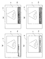
図3は、超音波診断装置の画面上に表示される断層像と重ならない位置に音声認識技術を手段として音声入力した所見情報の表示する方法の一例を示す図である。図3では、簡単化のため、超音波診断装置の画面を30、超音波診断装置の画面30上に表示された断層像を31、音声認識技術を手段として音声入力された所見情報を32と表示する。この表示方法は、超音波診断装置の画面30上に表示された断層像31に重ならない位置に音声認識技術を手段として音声入力された所見情報32a,32b,32c,32dを見易く表示することで断層像31を見ながらでも所見情報32を認識し易くしたものである。
FIG. 3 is a diagram showing an example of a method for displaying finding information input by voice using a voice recognition technique at a position that does not overlap with a tomographic image displayed on the screen of the ultrasonic diagnostic apparatus. In FIG. 3, for the sake of simplification, the screen of the ultrasonic diagnostic apparatus is 30, the tomographic image displayed on the
図3(a)は、超音波診断装置の画面30上に表示された断層像31と重ならない位置に所見情報32aを表示させるとともに所見情報32aの情報量に応じて、その所見情報32aを表示する領域を大きく変更する例を示すものである。例えば、通常時では、所見情報32aを表示する領域(200文字)、文字サイズを20ポイントとして所見情報を表示させることを所見情報制御部17bに設定しておく。そして所見情報を入力していく際、所見情報32aを表示する領域(200文字)からはみ出てしまう場合、所見情報制御部17bは、その領域を300文字のサイズを断層像31と重ならない横方向に大きくし、所見情報32aを領域内に収める。
FIG. 3 (a) displays the finding
また、図3(b)は、超音波診断装置の画面30上に表示された断層像31と重ならない位置に所見情報32bを表示させるとともに所見情報32bを表示する領域の背景色を変更する例を示すものである。
FIG. 3B shows an example in which the finding
検査結果状況に応じて、所見情報32bの背景色を変更することにより、検者の注意を促すことができる。例えば、体内に異常がないと診断した場合は、所見情報32bの背景色は水色、異常があると診断した場合は、所見情報32bの背景色はピンク色で表示することを所見情報制御部17bに予め設定しておき、マイク18、或いはマウス等の入力装置18aの入力信号に基づいて、所見情報制御部17bは所見情報32bの背景色を変更する。
By changing the background color of the finding
また、図3(c)は、超音波診断装置の画面30上に表示された断層像31と重ならない位置に所見情報32cを表示させるとともに所見情報32cを表示する文字サイズを変更することができる例を示すものである。
Further, in FIG. 3C, the finding
検査結果状況に応じて、所見情報32cの文字サイズを変更することにより、検者の注意を促すことができる。予めある用語(例えば、腫瘍、逆流)と文字サイズの関係を記憶装置(図示しない。)に登録させ、マイク18から入力される音声にある用語があれば、所見情報制御部17bは所見情報32cの文字サイズを変更して表示させる。
The examiner's attention can be urged by changing the character size of the finding
また、マイク18から入力されるマイク音量と文字サイズを関連付けて所見情報制御部17bに設定しておいてもよい。例えば、マイク音量が大きい場合、文字サイズを大きく表示させ、マイク音量が小さい場合、文字サイズを小さく表示させる。なお、所見情報制御部17bは、入力している文字が所見情報32cの表示領域からはみ出ると認識した時、自動的に文字サイズ縮小させ、全体を表示させることもできる。
Alternatively, the microphone volume input from the
また、図3(d)は、超音波診断装置の画面30上に表示された断層像31と重ならない位置に所見情報32dを表示させるとともに所見情報32dを表示する文字色を変更することができる例を示すものである。
Further, in FIG. 3D, the finding
検査結果状況に応じて、所見情報32dの文字色を変更しておくことにより、検者の注意を促すことができる。予めある用語(例えば、腫瘍、逆流)と文字色の関係を記憶装置(図示しない。)に登録させ、マイク18から入力される音声にある用語があれば、所見情報制御部17bは所見情報32dの文字色を例えば赤色で表示させる。
By changing the character color of the finding
上記図3のいずれの例においても、マイク18より入力された音声信号(例えば「領域拡大」「背景色を水色に表示」「文字サイズ2ポイント縮小」「文字色を赤色に表示」等)より、音声認識部17aは、その音声信号を認識し、制御部17はその音声信号に基づいて画面をリアルタイムに制御することができる。具体的には、音声信号と制御信号(領域情報、文字情報等)の関係を記憶装置(図示しない。)に予め定めておき、登録させておく。そして、音声認識部17aにおいて記憶装置に登録させてある音声信号を認識したら、制御部17は所定の制御信号を読み出して画面を制御している。
In any of the examples in FIG. 3 above, from the audio signal input from the microphone 18 (for example, “enlarge region”, “display background color in light blue”, “reduce character size 2 points”, “display character color in red”, etc.) The voice recognition unit 17a recognizes the voice signal, and the
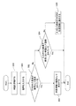
図4は、超音波診断装置の画面上に表示される断層像と重ならない位置に音声認識技術を手段として音声入力した所見情報の表示領域を音声認識技術を手段として音声入力した言葉によりコントロールする方法の一例を示すフローチャート図である。この方法は、所見情報の表示領域を音声入力した言葉によりコントロールすることで、例えば、両手が塞がっている場合でも所見情報の表示領域を自由に変えることができるようにしたものである。 FIG. 4 shows the display area of the findings information input by voice recognition technology as a means at a position not overlapping with the tomographic image displayed on the screen of the ultrasonic diagnostic apparatus by words input by voice recognition technology as means. It is a flowchart figure which shows an example of a method. In this method, the display area of the finding information can be freely changed even when both hands are closed, for example, by controlling the display area of the finding information with words inputted by voice.
まず、ステップS40では、所見情報の表示領域をコントロールする用語を登録する。所見情報の表示領域をコントロールする用語としては、例えば、「所見情報を上に表示」、「所見情報の表示領域を大きく」、「所見情報の表示領域を一時的に消去」等がある。そして、この用語に関連付けて所見情報制御部17bの制御信号(「所見情報を上に表示させる」、「所見情報の表示領域を大きく表示させる」、「所見情報の表示領域を一時的に消去させる」)をそれぞれ記憶装置に登録しておく。この用語は予めデフォルトとして超音波診断装置に登録させておいてもよく、任意に削除・追加していくこともできる。
First, in step S40, a term for controlling the display area of the finding information is registered. The terms for controlling the display area of the observation information include, for example, “display the observation information upward”, “enlarge the display area of the observation information”, “temporarily erase the display area of the observation information”, and the like. Then, in association with this term, the control signal of the observation
ステップS41では、音声認識技術を手段として、例えば、近距離無線通信方式のブルートゥースインターフェース手段でマイクから音声入力する。ステップS42では、音声入力された言葉が所見情報の表示領域をコントロールする用語として登録されているか否かの判定を行い、登録されている(yes)場合は、次のステップS43に進み、そうでない(no)の場合はステップS44に進む。ステップS43では、所見情報の表示領域を制御する用語として登録された用語の内容にもとづき、所見情報の表示領域を制御する。なお、この登録された用語は、制御信号に用いるので、所見文字情報として表示させないよう所見情報制御部17bを制御する。ステップS44では、所見情報の表示領域をコントロールする用語として登録されていない言葉は、所見情報として表示する。
In step S41, a voice is input from a microphone using, for example, a short-range wireless communication type Bluetooth interface unit using a voice recognition technique. In step S42, it is determined whether or not the word input by voice is registered as a term that controls the display area of the observation information. If it is registered (yes), the process proceeds to the next step S43, otherwise If (no), the process proceeds to step S44. In step S43, the display area of the finding information is controlled based on the contents of the term registered as the term for controlling the display area of the finding information. Since the registered term is used for the control signal, the finding
図5は、超音波診断装置の画面上に表示される断層像と重ならない位置に音声認識技術を手段として音声入力するときに音声入力された言葉をどのように所見情報として表示するかの方法の一例を示すフローチャート図である。この方法は、事前に用途に合わせた言葉を登録しておくことで、音声入力による所見情報の作成を効率良く行うことができるようにしたものである。まず、ステップS50では、音声入力された言葉をそのまま所見情報に表示せず暗号として表示する言葉を登録する。また、音声入力された言葉を所見情報に表示しない言葉を登録する。ステップS51では、音声認識技術を手段として、例えば、近距離無線通信方式のブルートゥースインターフェース手段でマイクから音声入力する。ステップS52では、音声入力された言葉が所見情報に暗号として表示する言葉として登録されているか否かの判定を行い、登録されている(yes)の場合は、次のステップS53に進み、そうでない(no)の場合は、ステップS54に進む。ステップS53では、音声入力された言葉を所見情報に暗号として表示する。ステップS54では、音声入力された言葉が所見情報に表示しない言葉として登録されているか否かの判定を行い、登録されている(yes)の場合は、所見情報には何も表示せず、そうでない(no)の場合は、ステップS55に進む。ステップS55では、音声入力された言葉をそのまま所見情報として表示する。このように言葉を暗号で画面に表示させたり、或いは言葉を画面に表示させなかったりすることにより、被検者に知らせたくない情報を隠したり、被検者のプライバシーを守ることができる。 FIG. 5 is a method of displaying speech input words as observation information when speech input is performed using speech recognition technology at a position that does not overlap with the tomographic image displayed on the screen of the ultrasonic diagnostic apparatus. It is a flowchart figure which shows an example. In this method, finding information by voice input can be efficiently performed by registering words suitable for the purpose in advance. First, in step S50, words to be displayed as ciphers are registered without being displayed in the observation information as they are. In addition, words that do not display the voice input words in the finding information are registered. In step S51, a voice is input from a microphone using a voice recognition technology as a means, for example, a Bluetooth interface means of a short-range wireless communication method. In step S52, it is determined whether or not the words input by voice are registered as words to be displayed as encryption in the observation information. If registered (yes), the process proceeds to the next step S53, otherwise If (no), the process proceeds to step S54. In step S53, the voice input word is displayed as encryption in the finding information. In step S54, it is determined whether or not the speech input word is registered as a word that is not displayed in the finding information. If it is registered (yes), nothing is displayed in the finding information. If not (no), the process proceeds to step S55. In step S55, the speech input words are displayed as finding information as they are. Thus, by displaying words on the screen with encryption or not displaying words on the screen, it is possible to hide information that is not desired to be notified to the subject or to protect the privacy of the subject.
図6は、超音波診断装置の画面上に表示される断層像と重ならない位置に音声認識技術を手段として音声入力した所見情報が表示されるが超音波診断装置の画面上に表示された所見情報を記憶する方法の一例を示す図である。図6では、簡単化のため、超音波診断装置の画面を60、超音波診断装置の画面60上に表示された断層像を61、音声認識技術を手段として音声入力された所見情報を62と表示する。また、断層像61を記憶したファイルを63、断層像61を記憶したファイルの画像情報部分を64、所見情報部分を65と表示する。この方法は、超音波診断装置の画面60上に表示された所見情報62を断層像61と同一のファイル63の中に貼り付けて記憶することで、所見情報62の管理を容易にするものである。
FIG. 6 shows the findings displayed on the screen of the ultrasonic diagnostic apparatus, although the information of the voice input using the voice recognition technique is displayed at a position that does not overlap with the tomographic image displayed on the screen of the ultrasonic diagnostic apparatus. It is a figure which shows an example of the method of memorize | storing information. In FIG. 6, for the sake of simplification, the screen of the ultrasonic diagnostic apparatus is 60, the tomographic image displayed on the
例えば、断層像61に対して音声入力した所見情報62を記憶装置(図示しない。)に記憶するとき、例えば、被検者名、被検者ID、検査日をキーワードとして断層像61を記憶したファイル63と所見情報62を結び付け、所見情報62を断層像61に記憶したファイル63の中に貼り付けるようにしたものである。また、例えば、被検者名、被検者ID、検査日をキーワードとして断層像61を記憶したファイル63と結び付くように所見情報62を断層像61に記憶したファイル63と別のファイルとして記憶するようにした。
For example, when the
一枚の断層像61に対し、所見情報62が複数ページにわたる場合、複数ページの所見情報62を断層像61に対応させて記憶させる。所見情報62にページ番号を表示させて記憶させ、表示する際、1ページ目をデフォルトとして表示させる。
When the
また、断層像61を時系列的に記憶させた動画像に所見情報62を対応させて記憶させ、ファイル63を作成することもできる。具体的に、動画像は生体信号、例えば心電波形に同期させて取得し、複数周期分の断層像を超音波診断装置内の記憶装置(図示しない。)に記憶させたり、動画像の各フレームに所見情報65を対応させて表示させるよう記憶装置に記憶させる。この場合、動画像でも把握しやすいように、複数フレーム、例えば3周期分のフレームに対して、同じ所見情報65を表示させるようにファイル63を作成したり、また、動画像のコマ送り、或いは早送り用に所見情報65を数秒間フリーズさせて表示させるようにファイル63を作成したりする。そして、表示する際、記憶装置に記憶されている動画像と共に所見情報を読み出し表示させる。
It is also possible to create the
なお、所見情報65の背景色を生体信号の起伏の激しい時相を濃い色で示し、起伏の低い時相を薄い色で表示したり、生体信号をピークポイントとして時相にしたがって徐々に輝度が変化するよう色を表示したりしてもよい。生体信号と所見情報65の背景色を同期させることにより、検者は所見情報65から生体情報を認識することができる。
Note that the background color of the
図7は、超音波診断装置上で記憶した所見情報ファイルをネットワーク上の他の診断支援システムに転送する方法の一例を示す図である。図7では、超音波診断装置を71、他の診断支援システムを72、超音波診断装置71と他の診断支援システム72が接続されているローカルエリアネットワーク(LAN)を73と表示する。この方法は、超音波診断装置71上で記憶された所見情報ファイルをローカルエリアネットワーク(LAN)73に接続された他の診断支援システム72に転送し、他の診断支援システム73上で診断レポートを作成する時、転送された所見情報ファイルを読み出すことにより例えばキーボードから所見情報を入力する時間を省くことができるようにしたものである。
FIG. 7 is a diagram showing an example of a method for transferring the finding information file stored on the ultrasonic diagnostic apparatus to another diagnostic support system on the network. In FIG. 7, 71 is displayed as the ultrasonic diagnostic apparatus, 72 is displayed as the other diagnostic support system, and 73 is a local area network (LAN) to which the ultrasonic
例えば、超音波診断装置71上で断層像を記憶したファイルの中に所見情報を貼り付けている場合は、断層像を記憶したファイルが他の診断支援システム72に転送された時に他の診断支援システム72上で所見情報を読み出せるようにしたものである。また、例えば、被検者名、被検者ID、検査日をキーワードとして所見情報を断層像を記憶したファイルと別のファイルとして記憶した場合は、断層像を記憶したファイルを他の診断支援システム72に転送した後から所見情報ファイルを他の診断支援システム72に転送することで、例えば、被検者名、被検者ID、検査日をキーワードとして断層像を記憶したファイルと結び付けて所見情報ファイルを読み出せるようにしたものである。記憶された画像が動画像であれば、動画像を構成する複数の断層像と、時系列に記憶させた複数の所見情報をそれぞれ対応付けて読み出される。
For example, when finding information is pasted in a file storing a tomographic image on the ultrasonic
図8は、他の診断支援システム上で作成する診断レポートの一例を示す図である。図8では、診断レポートを81、超音波診断装置から転送された断層像のファイルを読み出して表示したものを82、超音波診断装置から転送された所見情報のファイルを読み出して表示したものを83、診断レポート81に表示された内容を編集するボタンを84、診断レポート81に表示された内容を記憶するボタンを85と表示する。
FIG. 8 is a diagram illustrating an example of a diagnosis report created on another diagnosis support system. In FIG. 8, the diagnostic report is 81, the tomographic image file transferred from the ultrasonic diagnostic apparatus is read and displayed 82, and the observation information file transferred from the ultrasonic diagnostic apparatus is read and displayed 83 The button for editing the content displayed in the
例えば、診断レポート81示された内容を編集ボタン84により編集する時は、パスワードが必要とするようにしたものである。また、例えば、診断レポートに表示された内容を編集ボタン84により編集した後は、変更来歴が記録されるようにしたものである。
For example, when the contents shown in the
11…超音波探触子、12…超音波送受信部、13…シネメモリ、14…切換器、15…スキャンコンバータ、16…画像表示装置、17…制御部、18…マイク、18a…入力装置、19…通信制御部、20…超音波診断装置の画面、21a,21b…断層像、22a、22b…所見情報、30…超音波診断装置の画面、31…断層像、32a,32b,32c,32d…所見情報、60…超音波診断装置の画面、61…断層像、62…所見情報、63…断層像を記憶したファイル、64…断層像を記憶したファイルの画像情報部分、65…断層像を記憶したファイルの所見情報部分、71…超音波診断装置、72…他の診断支援システム、73…ローカルエリアネットワーク(LAN)、81…診断レポート、82…診断レポートの断層像表示部分、83…診断レポートの所見情報表示部分、84…診断レポートの編集機能ボタン、85…診断レポートの記録機能ボタン、100…診断支援システム
DESCRIPTION OF
Claims (4)
音声を入力する入力手段と、前記入力された音声を文字情報として認識する音声認識手段を備え、前記表示手段は、該文字情報に基づいた所見情報を前記超音波画像と共に表示することを特徴とする超音波診断装置。 Ultrasonic transmitting / receiving means for transmitting ultrasonic waves to the subject and receiving reflected echo signals from the subject, means for processing the received signals to form ultrasonic images, and displaying the ultrasonic images In an ultrasonic diagnostic apparatus comprising a display means,
And a voice recognition unit for recognizing the input voice as character information, wherein the display unit displays finding information based on the character information together with the ultrasonic image. Ultrasound diagnostic device.
Priority Applications (1)
| Application Number | Priority Date | Filing Date | Title |
|---|---|---|---|
| JP2004339711A JP2006141903A (en) | 2004-11-25 | 2004-11-25 | Ultrasonic diagnostic apparatus |
Applications Claiming Priority (1)
| Application Number | Priority Date | Filing Date | Title |
|---|---|---|---|
| JP2004339711A JP2006141903A (en) | 2004-11-25 | 2004-11-25 | Ultrasonic diagnostic apparatus |
Publications (2)
| Publication Number | Publication Date |
|---|---|
| JP2006141903A true JP2006141903A (en) | 2006-06-08 |
| JP2006141903A5 JP2006141903A5 (en) | 2007-11-29 |
Family
ID=36622226
Family Applications (1)
| Application Number | Title | Priority Date | Filing Date |
|---|---|---|---|
| JP2004339711A Pending JP2006141903A (en) | 2004-11-25 | 2004-11-25 | Ultrasonic diagnostic apparatus |
Country Status (1)
| Country | Link |
|---|---|
| JP (1) | JP2006141903A (en) |
Cited By (5)
| Publication number | Priority date | Publication date | Assignee | Title |
|---|---|---|---|---|
| JP2008245832A (en) * | 2007-03-29 | 2008-10-16 | Fujifilm Corp | Medical image display device and method |
| JP2009061040A (en) * | 2007-09-05 | 2009-03-26 | Panasonic Corp | Ultrasonic diagnostic system |
| JP2009080545A (en) * | 2007-09-25 | 2009-04-16 | Topcon Corp | Medical information processor |
| WO2020137162A1 (en) * | 2018-12-28 | 2020-07-02 | 富士フイルム株式会社 | Ultrasonic diagnosis device and control method for ultrasonic device |
| WO2021033303A1 (en) * | 2019-08-22 | 2021-02-25 | Hoya株式会社 | Training data generation method, learned model, and information processing device |
Citations (2)
| Publication number | Priority date | Publication date | Assignee | Title |
|---|---|---|---|---|
| JPH09122125A (en) * | 1995-09-01 | 1997-05-13 | Fujitsu Ltd | Ultrasonic module and ultrasonic diagnostic system |
| JP2004351212A (en) * | 2003-05-29 | 2004-12-16 | Ge Medical Systems Global Technology Co Llc | System and method of automatic annotation embedding device used in ultrasound imaging |
-
2004
- 2004-11-25 JP JP2004339711A patent/JP2006141903A/en active Pending
Patent Citations (2)
| Publication number | Priority date | Publication date | Assignee | Title |
|---|---|---|---|---|
| JPH09122125A (en) * | 1995-09-01 | 1997-05-13 | Fujitsu Ltd | Ultrasonic module and ultrasonic diagnostic system |
| JP2004351212A (en) * | 2003-05-29 | 2004-12-16 | Ge Medical Systems Global Technology Co Llc | System and method of automatic annotation embedding device used in ultrasound imaging |
Cited By (6)
| Publication number | Priority date | Publication date | Assignee | Title |
|---|---|---|---|---|
| JP2008245832A (en) * | 2007-03-29 | 2008-10-16 | Fujifilm Corp | Medical image display device and method |
| JP2009061040A (en) * | 2007-09-05 | 2009-03-26 | Panasonic Corp | Ultrasonic diagnostic system |
| JP2009080545A (en) * | 2007-09-25 | 2009-04-16 | Topcon Corp | Medical information processor |
| WO2020137162A1 (en) * | 2018-12-28 | 2020-07-02 | 富士フイルム株式会社 | Ultrasonic diagnosis device and control method for ultrasonic device |
| WO2021033303A1 (en) * | 2019-08-22 | 2021-02-25 | Hoya株式会社 | Training data generation method, learned model, and information processing device |
| JPWO2021033303A1 (en) * | 2019-08-22 | 2021-12-02 | Hoya株式会社 | Training data generation method, trained model and information processing device |
Similar Documents
| Publication | Publication Date | Title |
|---|---|---|
| US9561015B2 (en) | Method and apparatus for voice recording with ultrasound imaging | |
| JP5171829B2 (en) | Ultrasonic diagnostic apparatus and ultrasonic diagnostic system | |
| JPH09122125A (en) | Ultrasonic module and ultrasonic diagnostic system | |
| WO2017015902A1 (en) | Ultrasonic imaging system and method | |
| US20160113627A1 (en) | Ultrasound apparatus and information input method thereof | |
| JP4693433B2 (en) | Ultrasonic diagnostic equipment | |
| JP4643172B2 (en) | Portable diagnostic imaging equipment | |
| US11646107B2 (en) | Method for generating medical reports and an imaging system carrying out said method | |
| JP2006141903A (en) | Ultrasonic diagnostic apparatus | |
| JP2019103567A (en) | Ultrasound diagnostic device and ultrasonic probe | |
| JP2015226607A (en) | Ultrasonic diagnostic apparatus | |
| US6319202B1 (en) | Medical imaging method and apparatus and ultrasonic imaging method and apparatus | |
| JP5072492B2 (en) | Ultrasonic diagnostic equipment | |
| JP2003510154A (en) | Ultrasound diagnostic imaging device with voice communication | |
| JP2018061659A (en) | Ultrasonic inspection system, functional image sequence generation device, and inspection protocol creation device | |
| JP2018138087A (en) | Ultrasonic image processing apparatus | |
| WO2016105972A1 (en) | Report generation in medical imaging | |
| JP5361115B2 (en) | Ultrasonic diagnostic apparatus and image processing program | |
| KR100393020B1 (en) | Ultrasonic diagnostic system generating the same image as that of the source system and remote diagnostic method | |
| JP4693467B2 (en) | Ultrasonic diagnostic apparatus and image processing method | |
| JP3646584B2 (en) | Ultrasonic diagnostic equipment | |
| JP2012217593A (en) | Ultrasonograph and medical image management system | |
| JP2010094237A (en) | Ultrasonic diagnostic apparatus | |
| JP2006346467A (en) | Ultrasonic diagnostic system including high-capacity ultrasonic data storage device | |
| CN113951923A (en) | Ultrasonic imaging equipment for animals, ultrasonic imaging equipment and scanning method thereof |
Legal Events
| Date | Code | Title | Description |
|---|---|---|---|
| A521 | Written amendment |
Free format text: JAPANESE INTERMEDIATE CODE: A523 Effective date: 20071016 |
|
| A621 | Written request for application examination |
Free format text: JAPANESE INTERMEDIATE CODE: A621 Effective date: 20071016 |
|
| A977 | Report on retrieval |
Free format text: JAPANESE INTERMEDIATE CODE: A971007 Effective date: 20100805 |
|
| A131 | Notification of reasons for refusal |
Free format text: JAPANESE INTERMEDIATE CODE: A131 Effective date: 20100804 |
|
| A521 | Written amendment |
Free format text: JAPANESE INTERMEDIATE CODE: A523 Effective date: 20100930 |
|
| A02 | Decision of refusal |
Free format text: JAPANESE INTERMEDIATE CODE: A02 Effective date: 20101101 |