JP2006129948A - Gas feeding device - Google Patents
Gas feeding device Download PDFInfo
- Publication number
- JP2006129948A JP2006129948A JP2004319747A JP2004319747A JP2006129948A JP 2006129948 A JP2006129948 A JP 2006129948A JP 2004319747 A JP2004319747 A JP 2004319747A JP 2004319747 A JP2004319747 A JP 2004319747A JP 2006129948 A JP2006129948 A JP 2006129948A
- Authority
- JP
- Japan
- Prior art keywords
- pressure
- lumen
- abdominal
- air supply
- setting
- Prior art date
- Legal status (The legal status is an assumption and is not a legal conclusion. Google has not performed a legal analysis and makes no representation as to the accuracy of the status listed.)
- Granted
Links
Images


Abstract
Description
本発明は、腹腔内及び管腔内に気体を供給する送気装置に関する。 The present invention relates to an air supply device that supplies gas into an abdominal cavity and a lumen.
近年、腹腔鏡下外科手術は、広く行われている。この腹腔鏡下外科手術は、患者への侵襲を小さくする目的で、開腹することなく治療処置を行う場合が多い。
前記腹腔鏡下外科手術においては、患者の腹部に、例えば観察用の硬性内視鏡を体腔内に導く第1のトラカールと、治療処置を行う処置具を処置部位に導く第2のトラカールとが穿刺されて行われるようになっている。
In recent years, laparoscopic surgery has been widely performed. In this laparoscopic surgical operation, in order to reduce the invasion to a patient, a therapeutic treatment is often performed without laparotomy.
In the laparoscopic surgical operation, a first trocar that guides a rigid endoscope for observation into a body cavity, for example, and a second trocar that guides a treatment tool for performing a therapeutic treatment to a treatment site are provided on the abdomen of the patient. It is performed by puncture.
このような腹腔鏡下外科手術においては、前記硬性内視鏡の視野を確保する目的及び前記処置具を操作するための領域を確保する目的で、腹腔内に気腹用ガスとして例えば炭酸ガス(以下、CO2とも記載する)などを供給する気腹装置が用いられている。
また、胃や大腸などの管腔内の診断や処置を行う場合には、管腔内に挿入される細長で可撓性を有する挿入部を備えた軟性内視鏡と、この軟性内視鏡の処置具チャンネルを挿通して前記挿入部先端部のチャンネル開口から突出する処置具により治療処置を行う処置具とが用いられている。
In such a laparoscopic surgical operation, for example, carbon dioxide gas (eg, carbon dioxide gas) is used as an insufflation gas in the abdominal cavity for the purpose of securing the visual field of the rigid endoscope and the region for operating the treatment instrument. Hereinafter, an insufflation apparatus that supplies CO2) is used.
When performing diagnosis or treatment in a lumen such as the stomach or large intestine, a flexible endoscope having an elongated and flexible insertion portion inserted into the lumen, and the flexible endoscope And a treatment tool that performs a therapeutic treatment using a treatment tool that is inserted through the treatment tool channel and protrudes from a channel opening at the distal end portion of the insertion portion.
このような内視鏡観察下で患者の胃や大腸などの管腔内の診断や処置などの医療処置を行う際にも、前記軟性内視鏡の視野を確保する目的及び前記処置具を操作するための領域を確保する目的で、管腔内に管腔用ガスとして空気などの気体が注入される場合もある。この場合、管腔に供給される空気は、送気ポンプによって管腔内に送気される場合が多いが、上述した炭酸ガスを用いることも可能である。 The purpose of ensuring the field of view of the flexible endoscope and the operation of the treatment tool also when performing medical treatment such as diagnosis and treatment in the lumen of the patient's stomach or large intestine under such endoscopic observation In order to secure a region for this purpose, a gas such as air may be injected into the lumen as a lumen gas. In this case, the air supplied to the lumen is often supplied into the lumen by an air supply pump, but the above-described carbon dioxide gas can also be used.
近年、新たな試みとして、腹腔鏡下外科手術において、腹腔内に前記硬性内視鏡を挿入すると共に、管腔内に前記軟性内視鏡を挿入して処置部位を特定して治療を行うことがある。この場合にも、管腔内に挿入した前記軟性内視鏡から例えば空気を送り込んで管腔を膨らませることがある。
このような場合に、生体に吸収され易い、例えば炭酸ガスを大腸に供給する装置であるエンドスコープ・CO2・レギュレータ(以下、ECRと称す)を使用することが考えられる。
In recent years, as a new attempt, in laparoscopic surgery, the rigid endoscope is inserted into the abdominal cavity and the flexible endoscope is inserted into the lumen to identify the treatment site and perform treatment. There is. Also in this case, for example, air may be sent from the flexible endoscope inserted into the lumen to inflate the lumen.
In such a case, it is conceivable to use an endoscope / CO2 / regulator (hereinafter referred to as ECR) which is a device that is easily absorbed by a living body and supplies carbon dioxide to the large intestine.
図13は、前記ECRを備えた従来の腹腔鏡下外科手術システムの全体構成図である。
図13に示すように、前記従来の腹腔鏡下外科手術システム150では、使用する周辺医療用機器の種類が多く、複数の医療用機器が数台のカート160,170に分けて搭載されている。また、これらのカート160,170は、ほぼ一ヶ所に集められて操作性が向上されている。
FIG. 13 is an overall configuration diagram of a conventional laparoscopic surgical system having the ECR.
As shown in FIG. 13, in the conventional laparoscopic
例えば、前記第1のカート160には、モニタ161,集中表示パネル162,第1TVカメラ163a,第1光源164a,第2TVカメラ163b,第2光源164b,システムコントローラ165,ビデオミキサー166,VTR167,分配器168,通信用コネクタ169などが搭載されている。また、前記第2カート170には、モニタ171,高周波焼灼装置172,気腹器173,CO2ボンベ174,吸引ボトル175,分配器176,通信用コネクタ177などが搭載されている。
For example, the
各種医療用機器は、前記第1のカート160及び前記第2のカート170内で図示しない通信ケーブルを介してそれぞれのカート160,170に配設されている分配器168,176と電気的に接続されている。また、前記第1のカート160と前記第2のカート170とは、通信ケーブルを内設したユニバーサルケーブル178を介して電気的に接続されている。更に、前記第1カート160及び前記第2カート170と前記周辺機器コントローラ180とは、通信ケーブルを内設したユニバーサルコード182を介して電気的に接続されている。
Various medical devices are electrically connected to
前記周辺機器コントローラ180には、第1のカート160及び第2のカート170に搭載されている医療用機器のうち頻繁に使う必要のある設定スイッチが集中制御操作部181に集約されている。
更に、前記第1カート160の第1光源164a又は、第2光源164bに、炭酸ガス(CO2)供給用チューブ192を介してECR190が接続されている。このECR190は、炭酸ガスボンベ(以下、CO2ボンベとも記載する)191に接続されている。
In the
Further, an ECR 190 is connected to the
このように、内視鏡下で外科手術を行う従来の腹腔鏡下外科手術システムに前記ECR190を設けて構成した場合には、前記腹腔鏡下外科手術システム150は、前記気腹器173及びCO2ボンベ174と、前記ECR190及びCO2ボンベ191とを別々に配置することになる。
As described above, when the ECR 190 is provided in a conventional laparoscopic surgical system that performs surgery under an endoscope, the laparoscopic
一方、腹腔内に炭酸ガスを送気する気腹器などの送気装置においては、従来より種々提案がなされている。
例えば、特開2000−139830号公報には、送気流量が設定値に達していない場合には、圧力調整部である電空比例弁(又は、電磁比例弁とも言う)の出力圧力が上昇するように制御信号を前記電空比例弁に供給して、生体内圧が設定値となるように送気流量を制御するようにした送気装置が開示されている。
On the other hand, various proposals have heretofore been made for an insufflation apparatus such as an insufflator for feeding carbon dioxide into the abdominal cavity.
For example, in Japanese Patent Laid-Open No. 2000-139830, when the air supply flow rate does not reach the set value, the output pressure of the electropneumatic proportional valve (also referred to as an electromagnetic proportional valve) that is a pressure adjusting unit increases. Thus, an air supply device is disclosed in which a control signal is supplied to the electropneumatic proportional valve to control the air supply flow rate so that the in-vivo pressure becomes a set value.
また、特開平8−256972号公報には、気体供給源から気腹用の挿入具に至る気体供給管路の流通状態を切替える複数の管路切替部(電磁弁)をマニホールドバルブと一体的に組み付けて構成することにより、流量制御部の小型化を図るようにした気腹装置が開示されている。
また、特開2000−139823号公報には、空気を管腔に送気し、内部を一定の圧力に保つ送気装置が開示されている。
Japanese Patent Laid-Open No. 2000-139823 discloses an air supply device that supplies air to a lumen and keeps the inside at a constant pressure.
しかしながら、図13に示す従来例の腹腔鏡下外科手術システムは、腹腔内に前記硬性内視鏡を挿入すると共に、管腔内に前記軟性内視鏡を挿入して処置部位を特定して治療を行うようになっている。この場合、前記ECRは、通常の内視鏡検査に適した設計、即ち、大腸などの管腔内のみに適した送気圧で炭酸ガスを前記軟性内視鏡を介して送気するように設計されているため、腹腔鏡下では気腹圧の影響で十分に炭酸ガスを供給することが困難になってしまう。 However, in the conventional laparoscopic surgical system shown in FIG. 13, the rigid endoscope is inserted into the abdominal cavity, and the flexible endoscope is inserted into the lumen to identify the treatment site and perform treatment. Is supposed to do. In this case, the ECR is designed to be suitable for normal endoscopy, i.e., to deliver carbon dioxide through the flexible endoscope at a gas pressure suitable only for a lumen such as the large intestine. Therefore, under the laparoscope, it becomes difficult to supply carbon dioxide sufficiently due to the influence of the pneumoperitoneum pressure.
また、前記従来例では、気腹器と前記ECRとを別々に用意しなくてはならず、準備が煩雑になってしまったり、スペース的に非効率であるといった問題点があった。
そこで、例えば、炭酸ガスを使用する、前記気腹器と前記ECRとを単純に一体化して構成した場合、装置が大型化し、コストも上昇する。また、気腹用送気と管腔用送気とでは、各送気圧がそれぞれ異なるために、それぞれに適した送気圧で炭酸ガスを送気しなければならない。
Further, in the conventional example, the insufflator and the ECR must be prepared separately, which causes problems such as complicated preparation and space inefficiency.
Therefore, for example, when the gastrointestinal device and the ECR using carbon dioxide gas are simply integrated, the apparatus becomes large and the cost increases. In addition, since the air supply for insufflation and the air supply for lumen are different from each other, the carbon dioxide gas must be supplied at an appropriate air supply pressure.
しかしながら、前記特開2000−139830号公報、前記特開平8−256972号公報、前記特開2000−139823号公報に記載の従来例では、気腹器のみの構成しか述べられてはおらず、上述したように前記気腹器と前記ECRとを一体化して構成した送気装置に関する技術については開示がなされていない。
また、管腔臓器は、腹腔の内部にあるため、管腔内部の圧力は腹腔圧の影響を受ける。また、管腔内部へ送気を行って管腔が膨脹すると、腹腔内の容積が圧迫されるため、腹腔圧にも影響を受ける。このように、管腔内部の圧力と腹腔内の圧力は互いに影響を及ぼしあうために、この両者に送気を行って膨らませる場合、安定して膨らみを保つことが困難であった。
However, in the conventional examples described in Japanese Patent Application Laid-Open No. 2000-139830, Japanese Patent Application Laid-Open No. 8-256972, and Japanese Patent Application Laid-Open No. 2000-139823, only the configuration of the insufflator is described. As described above, there is no disclosure about a technique related to an air feeding device configured by integrating the insufflator and the ECR.
Further, since the luminal organ is inside the abdominal cavity, the pressure inside the lumen is influenced by the abdominal pressure. Further, when the air is blown into the lumen and the lumen is expanded, the volume in the abdominal cavity is compressed, so that the abdominal pressure is also affected. As described above, since the pressure inside the lumen and the pressure inside the abdominal cavity influence each other, it is difficult to stably keep the bulge when inflating both of them by supplying air.
本発明は、上述した点に鑑みてなされたもので、腹腔内と管腔内とでそれぞれに適した圧力となるように気体を送気可能で、小型で安価な送気装置を提供することを目的とする。 The present invention has been made in view of the above points, and provides a small and inexpensive air supply device capable of supplying gas so as to have a pressure suitable for each of the abdominal cavity and the lumen. With the goal.
本発明による送気装置は、所定の気体を供給する供給源と、前記供給源から供給される所定の気体を患者の第1の体腔内へ供給する第1の管路と、前記供給源から供給される所定の気体を前記患者の前記第1の体腔内又は近傍の第2の体腔内へ供給する第2の管路と、前記供給源から前記第1及び第2の管路を介して前記患者に供給される気体のそれぞれの圧力を調整する圧力調整手段と、前記第1の管路の圧力を検出する第1の圧力検出手段と、前記第2の管路の圧力を検出する第2の圧力検出手段と、前記第1及び第2の圧力検出手段による検出結果に基づき、前記第2の体腔内の圧力が、前記第1の体腔内の圧力よりも所定値高くなるように前記圧力調整手段を制御する制御手段と、を備えたことを特徴としている。 An air supply device according to the present invention includes a supply source for supplying a predetermined gas, a first conduit for supplying a predetermined gas supplied from the supply source into a first body cavity of a patient, and the supply source. A second line for supplying a predetermined gas to be supplied into the first body cavity of the patient or a second body cavity in the vicinity of the patient; and from the supply source through the first and second lines. A pressure adjusting means for adjusting the pressure of each gas supplied to the patient; a first pressure detecting means for detecting the pressure of the first pipe; and a first pressure detecting means for detecting the pressure of the second pipe. Based on the detection results of the second pressure detection means and the first and second pressure detection means so that the pressure in the second body cavity is higher than the pressure in the first body cavity by a predetermined value. And a control means for controlling the pressure adjusting means.
本発明の送気装置は、腹腔内と管腔内とでそれぞれに適した圧力となるように気体を送気可能で、小型で安価に構成できるといった利点がある。 The air supply device of the present invention has an advantage that gas can be supplied so as to have pressures suitable for each of the abdominal cavity and the lumen, and can be configured in a small size and at low cost.
以下、図面を参照して本発明の実施例を説明する。 Embodiments of the present invention will be described below with reference to the drawings.
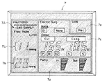
図1ないし図10は本発明の実施例1に係り、図1は実施例1の送気装置を備えた腹腔鏡下外科手術システムの全体構成図、図2は図1の集中操作パネルの画像構成例、図3は図1の集中表示パネルの画像構成例、図4は図1の送気装置の設定操作部及び表示部を示す構成図、図5は図1の送気装置の構成を説明するブロック図、図6は図5の制御部の制御動作例を示すフローチャート、図7は図6のフローチャートによる制御を示す時間に対する腹腔内の圧力(以下、腹腔圧と略記する)を表すグラフ、図8は図7のグラフの腹腔圧変化を行うための時間に対する電空比例弁の出力圧力の変化を表すグラフ、図9は図6のフローチャートによる制御を示す時間に対する管腔内の圧力(以下、管腔圧と略記する)を表すグラフ、図10は図9のグラフの管腔圧変化を行うための時間に対する電空比例弁の出力圧力の変化を表すグラフである。 1 to 10 relate to a first embodiment of the present invention, FIG. 1 is an overall configuration diagram of a laparoscopic surgical system including the air feeding device of the first embodiment, and FIG. 2 is an image of a centralized operation panel of FIG. 3 is an example of the image configuration of the centralized display panel of FIG. 1, FIG. 4 is a configuration diagram showing a setting operation unit and a display unit of the air supply device of FIG. 1, and FIG. 5 is a configuration of the air supply device of FIG. FIG. 6 is a flowchart showing an example of the control operation of the control unit in FIG. 5, and FIG. 7 is a graph showing pressure in the abdominal cavity (hereinafter abbreviated as abdominal pressure) with respect to time indicating control by the flowchart in FIG. 8 is a graph showing the change in the output pressure of the electropneumatic proportional valve with respect to the time for changing the abdominal pressure in the graph of FIG. 7, and FIG. 9 is the pressure in the lumen with respect to time showing the control according to the flowchart of FIG. FIG. 10 is a graph showing (hereinafter abbreviated as luminal pressure), FIG. It is a graph showing a change in output pressure of the electro-pneumatic proportional valve with respect to time for performing intraluminal pressure change in the graph.
図1に示すように本実施例の腹腔鏡下外科手術システム(以下、外科手術システムと略記する)1は、第1内視鏡システム2と、第2内視鏡システム3と、送気システム4を備えるとともに、システムコントローラ5と、表示装置であるモニタ6と、集中表示パネル7と、集中操作パネル8と、カート9とを備えて主に構成されている。
As shown in FIG. 1, a laparoscopic surgical system (hereinafter abbreviated as a surgical system) 1 of the present embodiment includes a
尚、符号10は、患者である。符号11は、手術台であり、患者10が横たわる。符号12は、電気メス装置である。電気メス装置12には、手術器具である電気メス13が接続される。符号14、15、16は、患者の腹部に穿刺されるトラカールである。第1トラカール14は、後述する内視鏡を腹腔内に導くトラカールである。第2トラカール15は、組織の切除や処置を行う電気メス13等の処置具を腹腔内に導くトラカールである。第3トラカール16は、送気システム4を構成する送気装置(後述)から供給される気腹用気体である、例えば生体に吸収され易い二酸化炭素ガス(以下、炭酸ガスと記載する)を腹腔内に導くトラカールである。尚、炭酸ガスを第1トラカール14又は第2トラカール15から腹腔内に導くようにしてもよい。
第1内視鏡システム2は、第1の内視鏡である例えば挿入部が硬性な硬性内視鏡21と、第1光源装置22と、第1のカメラコントロールユニット(以下、第1CCUと略記する)23と、内視鏡用カメラ24とで主に構成されている。
硬性内視鏡21の挿入部(不図示)は、第1トラカール14に挿通配置される。挿入部内には、被写体像を伝送するリレーレンズ(不図示)等で構成される観察光学系やライトガイド(不図示)等で構成される照明光学系を備えている。挿入部の基端部には、観察光学系によって伝送された光学像を観察する接眼部25が設けられている。接眼部25には、内視鏡用カメラ24が着脱自在に配設される。内視鏡用カメラ24の内部には、撮像素子(不図示)が備えられている。
The
An insertion portion (not shown) of the
第1光源装置22は、硬性内視鏡21に照明光を供給する。第1CCU23は、内視鏡用カメラ24の撮像素子に結像して光電変換された電気信号を映像信号に変換し、例えばモニタ6や集中表示パネル7にその映像信号を出力する。このことによって、モニタ6又は集中表示パネル7の画面上に硬性内視鏡21でとらえた被写体の内視鏡画像が表示される。
尚、硬性内視鏡21と第1光源装置22とは、硬性内視鏡21の基端部側部から廷出するライトガイドケーブル26によって接続される。第1CCU23と内視鏡用カメラ24とは、撮像ケーブル27によって接続される。
The first
The
第2内視鏡システム3は、第2の内視鏡である大腸等の管腔内に挿入される軟性な挿入部34を有する軟性内視鏡31と、第2光源装置32と、第2カメラコントロールユニット(以下、第2CCUと略記する)33とで主に構成されている。
軟性内視鏡31は、挿入部34と、操作部35と、ユニバーサルコード36とを備えて構成されている。操作部35には、送気・送水スイッチ35aや吸引スイッチ35b、図示しない湾曲部を湾曲動作させる湾曲操作ノブ37、図示しない処置具チャンネルに連通する処置具挿通口38が設けられている。ユニバーサルコード36の基端部には、光源コネクタ36aが設けられている。
The
The
第2光源装置32は、軟性内視鏡31に照明光を供給する。この第2光源装置32には、光源コネクタ36aが着脱自在に接続される。光源コネクタ36aを第2光源装置32に接続することによって、照明光が図示しないライトガイドファイバを伝送されて挿入部34の図示しない先端部に設けられている照明窓から出射される。
第2CCU33は、軟性内視鏡31の挿入部34の図示しない先端部に設けられている撮像素子に結像して光電変換された電気信号を映像信号に変換し、例えばモニタ6や集中表示パネル7にその映像信号を出力する。このことによって、モニタ6又は集中表示パネル7の画面上に軟性内視鏡31でとらえた被写体の内視鏡画像が表示される。尚、符号39は、光源コネクタ36aに設けられている電気コネクタ36bと第2CCU33とを電気的に接続する電気ケーブルである。
The second light source device 32 supplies illumination light to the
The
送気システム4は、送気装置41と、炭酸ガス供給部である炭酸ガスボンベ42と、挿通口用アダプタ(以下、アダプタと略記する)43と、管腔供給ガス制御スイッチであるフットスイッチ44と、チューブ45a、45bとで主に構成されている。炭酸ガスボンベ42には、炭酸ガスが液化した状態で貯留されている。
送気装置41には、第1の供給口金である腹腔用供給口金41Aと、第2の供給口金である管腔用供給口金41Bとが設けられている。腹腔用供給口金41Aには、腹腔用チューブ45aの一端部が連結され、この腹腔用チューブ45aの他端部は、第3トラカール16に連結される。管腔用供給口金41Bには、管腔用チューブ45bの一端部が連結され、この管腔用チューブ45bの他端部は、アダプタ43の例えば側部に設けられているチューブ連結部43aに連結される。
The
The
フットスイッチ44は、例えばスイッチ部44aが足によって押圧されている状態のとき炭酸ガス供給状態になって、管腔用供給口金41Bを介して炭酸ガスを供給する。そして、スイッチ部44aから足を離すことによって、炭酸ガス供給停止状態になって炭酸ガスの供給が停止される。
送気装置41と炭酸ガスボンベ42とは、高圧ガス用チューブ46によって連結されている。送気装置41とフットスイッチ44とは、フットスイッチケーブル44bによって電気的に接続されている。前記チューブ45a、45bは、シリコンやテフロン(登録商標)で形成されている。
The
The
システムコントローラ5は、外科手術システム1全体を一括して制御を行う。システムコントローラ5には、図示しない通信回線を介して、集中表示パネル7及び集中操作パネル8や、内視鏡周辺装置である電気メス装置12、光源装置22、32、CCU23、33及び送気装置41等が双方向通信を行えるように接続されている。
モニタ6の画面上には、第1CCU23又は第2CCU33から出力される映像信号を受けて、硬性内視鏡21又は軟性内視鏡31でとらえた被写体の内視鏡画像が表示されるようになっている。
The
On the screen of the
集中表示パネル7には、液晶ディスプレイ等の表示画面が設けられている。集中表示パネル7は、システムコントローラ5に接続されていることにより、表示画面上に前記被写体の内視鏡画像とともに内視鏡周辺装置の動作状態の集中表示が可能になっている。
集中操作パネル8は、液晶ディスプレイ等の表示部と、この表示部の表示面上に一体的に設けられたタッチセンサ部とで構成されている。集中操作パネル8の表示部には、各内視鏡周辺装置の操作スイッチ等を設定画面として表示させる表示機能とともに、タッチセンサ部の所定領域を触れることによって操作スイッチを操作する操作機能とを有している。
The
The
集中操作パネル8は、システムコントローラ5に接続されていることにより、表示部に表示されているタッチセンサ部を適宜操作することによって、各内視鏡周辺装置にそれぞれ設けられている操作スイッチを直接操作したのと同様に、この集中操作パネル8上で遠隔的に各種操作或いは設定等を行える。
カート9には、周辺装置である電気メス装置12、光源装置22、32、CCU23、33及び送気装置41と、システムコントローラ5と、集中表示パネル7と、集中操作パネル8と炭酸ガスボンベ42等が搭載される。
Since the
The
図2には、図1の前記集中操作パネル8の構成例が示されている。
図2に示すように、前記集中操作パネル8には、送気装置41による腹腔用又は管腔用の気腹流量を調節するための設定操作ボタン8aと、前記電気メス装置(高周波燃焼装置)12の出力値を調節するための操作ボタン8bと、前記第1CCU23,第2CCU33の色調を調節するための操作ボタン8cと、モニタ6に表示する映像情報の表示切換えを指示するための操作ボタン8dと、前記VTRによる録画又は録画停止を指示するための操作ボタン8eと、前記第1光源装置22及び前記第2光源装置32の光量を調節するための操作ボタン8fとが設けられている。
FIG. 2 shows a configuration example of the
As shown in FIG. 2, the
図3には、図1の前記集中表示パネル7の表示画面の一例が示されている。
図3に示すように、例えば、前記集中表示パネル7の表示画面上には、前記システムコントローラ5が通信制御している機器である送気装置41、電気メス装置12、送水・吸引ポンプ(図示せず)、VTR(図示せず)の機能に関する設定・動作状態がそれぞれの表示エリア7A(7a,7b),7c,7d,7eに表示されるようになっている。尚、前記表示エリア7Aは、前記送気装置41に関する設定、動作状態を表示するようになっており、管腔圧表示7a及び腹腔圧表示7bや炭酸ガス残量表示、流量表示等を表示している。
FIG. 3 shows an example of the display screen of the
As shown in FIG. 3, for example, on the display screen of the
次に、前記送気装置41のフロントパネルの構成例について図4を参照しながら説明する。
図4に示すように、前記送気装置41のフロントパネルには、操作情報を入力するための設定操作手段である設定操作部63及び表示部64が設けられている。これら設定操作部63及び表示部64は、炭酸ガスボンベ42に関する設定、操作及び表示のための供給源設定表示部41Cと、腹腔に関する設定、操作及び表示のための腹腔用設定表示部41Dと、管腔に関する設定、操作及び表示のための管腔用設定表示部41Eとに分割されている。また、前記腹腔用設定表示部41Dの下側には、気腹用送気ポートとしての腹腔用供給口金41Aが設けられている。更に、前記管腔用設定表示部41Eの下側には、管腔用送気ポートとしての管腔用供給口金41Bが設けられている。このような配置構成により、術者にとって前記送気装置41の操作がし易く、また各表示が見易いものとなっている。
Next, a configuration example of the front panel of the
As shown in FIG. 4, the front panel of the
前記供給源設定表示部41Cには、前記設定操作部63である電源スイッチ71、送気開始ボタン72、送気停止ボタン73、前記表示部64であるガス残量表示部76が設けられている。
前記腹腔用設定表示部41Dには、前記表示部64である腹腔圧表示部77a,腹腔圧設定表示部77b、腹腔流量表示部78a,腹腔流量設定表示部78b、送気ガス総量表示部79及び圧力警告灯84、前記設定操作部63である腹腔圧設定ボタン74a,74b、腹腔送気ガス流量設定ボタン75a,75b、腹腔指示ボタン82が設けられている。
前記管腔用設定表示部41Eには、前記表示部64である管腔圧表示部80a,管腔圧設定表示部80b、前記設定操作部63である管腔指示ボタン83、管腔圧設定ボタン81a,81bが設けられている。
前記電源スイッチ71は、送気装置41の電源をオン状態又はオフ状態に切り替えるスイッチである。この電源スイッチ71をオン状態にすることによってフットスイッチ44が操作可能な状態になる。前記送気開始ボタン72は、腹腔への炭酸ガスの供給開始を指示するボタンである。前記送気停止ボタン73は、腹腔への炭酸ガスの供給停止を指示するスイッチである。
The supply source setting
The abdominal cavity
The lumen
The
腹腔圧設定ボタン74a、腹腔送気ガス流量設定ボタン75a、管腔圧設定ボタン81aは、ボタン操作することによって設定値を徐々に高くなる方向に変化させられる。一方、腹腔圧設定ボタン74b及び腹腔送気ガス流量設定ボタン75b、管腔圧設定ボタン81bは、ボタン操作することによって設定値を徐々に低くなる方向に変化させられる。
ガス残量表示部76には、炭酸ガスボンベ42内の炭酸ガスの残量が表示される。
The setting values of the abdominal
The remaining gas
腹腔圧表示部77aには、後述の第1圧力センサ95Aで測定された測定結果が表示される。一方、腹腔圧設定表示部77bには、例えば腹腔圧設定ボタン74a、74bをボタン操作して設定された圧力設定値が表示される。
腹腔流量表示部78aには、後述の第1流量センサ96Aによって測定された測定結果が表示される。一方、腹腔流量設定表示部78bには、腹腔送気ガス流量設定ボタン75a、75bをボタン操作して設定された流量設定値が表示される。
A measurement result measured by a
The abdominal flow
送気ガス総量表示部79には、後述の第1流量センサ96A及び第2流量センサ96Bの計測値に基づいて制御部98のCPUで演算によって求められる送気ガス総量が表示される。
管腔圧表示部80aには、後述の第2圧力センサ95Bによって測定された測定結果が表示される。一方、管腔圧設定表示部80bには、管腔圧設定ボタン81a、81bをボタン操作して設定された圧力設定値が表示される。
The total gas supply
The lumen
前記腹腔指示ボタン82は、前記送気装置41による炭酸ガスの送気を腹腔内に対して行う腹腔送気モードを選択するための指示ボタンであり、ボタン操作することにより、前記腹腔送気モードが選択されるようになっている。
前記管腔指示ボタン83は、前記送気装置41による炭酸ガスの送気を管腔内に対して行う管腔送気モードを選択するための指示ボタンであり、ボタン操作することにより、前記管腔送気モードが選択されるようになっている。
前記圧力警告灯84は、例えば消灯状態から点滅表示状態又は赤色発光状態に変化して、腹腔圧が設定値より高くなったことを術者等に告知するようになっている。尚、管腔用の前記設定表示部41Eに、前記圧力警告灯84と同様の管腔圧力警告灯を設けても良い。
尚、腹腔圧又は管腔圧の設定、腹腔及び管腔の送気ガス流量の設定等は、前記集中操作パネル8によっても行える。また、前記集中表示パネル7に、腹腔圧表示部77a、腹腔圧設定表示部77b、腹腔流量表示部78a,腹腔流量設定表示部78b、管腔圧表示部80a,管腔圧設定表示部80b、送気ガス総量表示部79に表示される値の中から術者が予め指定した1つ又は複数の値を表示させるようにしてもよい。
The abdominal
The
The
The setting of the abdominal pressure or the lumen pressure, the setting of the gas flow rate of the abdominal cavity and the lumen, and the like can also be performed by the
次に、前記送気装置41の内部構成について図5を参照しながら説明する。
図5に示すように送気装置41内には、供給圧センサ91、減圧器92、圧力調整手段である電空比例弁93、第1電磁弁94A及び第2電磁弁94B、第1及び第2の圧力検知手段である第1圧力センサ95A及び第2圧力センサ95B、第1流量センサ96A及び第2流量センサ96B、排出部である第1リリーフ弁97A及び第2リリーフ弁97B、制御手段である制御部98が主に設けられている。
Next, the internal configuration of the
As shown in FIG. 5, in the
また、送気装置41には、前記腹腔用供給口金41A,管腔用供給口金41Bに加えて、高圧口金99、スイッチ用コネクタ100、前記設定操作部63、前記表示部64とが設けられている。
前記電空比例弁93の下流側は2つに分岐しており、一方は第1電磁弁94A、第1圧力センサ95A、第1流量センサ96A、第1リリーフ弁97A、腹腔用供給口金41A、腹腔用チューブ45aで構成される第1の管路としての腹腔用流路であり、他方は、第2電磁弁94B、第2圧力センサ95B、第2流量センサ96B、第1リリーフ弁97A、管腔用供給口金41B、管腔用チューブ45bで構成される第2の管路としての管腔用流路である。
The
The downstream side of the electropneumatic
前記高圧口金99には、前記高圧ガス用チューブ46が接続される。前記スイッチ用コネクタ100には、前記フットスイッチケーブル44bが接続される。このスイッチ用コネクタ100は、制御部98に接続されている。従って、フットスイッチ44から出力される管腔内に炭酸ガスを供給するか否かを指示する制御信号が制御部98に入力されるようになっている。
前記供給圧センサ91は、前記炭酸ガスボンベ42から供給された炭酸ガスの圧力を計測して制御部98に出力する。前記減圧器92は、前記高圧口金99を介して供給された炭酸ガスを所定の圧力に減圧する。
The high
The supply pressure sensor 91 measures the pressure of the carbon dioxide gas supplied from the
前記電空比例弁93は、図示しないマグネットコイルと磁針とから形成された電磁石によって、圧力制御用薄膜に作用する減圧ばねの力を変化させて圧力を電気的に調節するように構成されており、入力電圧(電流)に比例して開度が可変するようになっている。この電空比例弁93は、制御部98から出力される制御信号に基づいて、前記減圧器92で減圧された炭酸ガスの圧力を0〜500mmHgの範囲内で減圧可能である。
The electropneumatic
前記第1電磁弁94A及び前記第2電磁弁94Bは、制御部98から出力される制御信号に基づいて開閉動作される。第1圧力センサ95Aは、腹腔圧を測定して、その測定結果を制御部98に出力する。第2圧力センサ95Bは、管腔圧を測定して、その測定結果を制御部98に出力する。第1流量センサ96Aは、腹腔用供給口金41Aに供給されていく炭酸ガスの流量を測定して、その測定結果を制御部98に出力する。第2流量センサ96Bは、管腔用供給口金41Bに供給されていく炭酸ガスの流量を測定して、その測定結果を制御部98に出力する。
The first electromagnetic valve 94A and the second electromagnetic valve 94B are opened and closed based on a control signal output from the
前記第1リリーフ弁97Aは、制御部98からの制御信号に基づいて開閉動作される。第1リリーフ弁97Aが開状態のとき、第1リリーフ弁97Aに送られたガスは、大気中に放出される。前記第2リリーフ弁97Bは、制御部98からの制御信号に基づいて開閉動作される。第2リリーフ弁97Bが開状態のとき、第2リリーフ弁97Bに送られたガスは、大気中に放出される。
これにより、腹腔内又は管腔内の炭酸ガスが大気中に放出されて、腹腔圧又は管腔圧が減圧されるようになっている。
The first relief valve 97A is opened and closed based on a control signal from the
As a result, carbon dioxide in the abdominal cavity or lumen is released into the atmosphere, and the abdominal cavity pressure or luminal pressure is reduced.
従って、炭酸ガスボンベ42内に貯留されている液状の炭酸ガスは、送気装置41内に送られ減圧器92で減圧された後、制御部98から出力される制御信号に基づいて、腹腔用流路を介して腹腔内又は管腔用流路を介して管腔内に供給されるようになっている。
また、送気装置41には、メモリ101が設けられている。このメモリ101には、前回設定された設定値が記憶されるようになっている。
Therefore, the liquid carbon dioxide gas stored in the carbon
In addition, the
前記メモリ101は電源投入時に前回設定された設定値が前記制御部98から読み出され、この読み出された設定値は腹腔圧設定表示部77b、管腔圧設定表示部80b、腹腔流量設定表示部78b等の各設定表示部に初期値として表示されるようになっている。
前記制御部98は、前記第1及び第2圧力センサ95A,95B、前記第1及び第2流量センサ96A,96Bの検知結果に基づき、前記電空比例弁93、前記第1及び第2電磁弁94A,94b、前記第1及び第2リリーフ弁97A,97Bを制御して腹腔内と管腔内とでそれぞれに適した圧力となるように適宜調節し、両者を一定の圧力に保つようにしている。
The memory 101 reads the set value previously set when the power is turned on from the
Based on the detection results of the first and
また、前記制御部98は、前記設定操作部63に入力される操作情報に基づき、前記管腔圧が前記腹腔圧よりも所定値高くなるように前記腹腔圧及び前記管腔圧のうち、どちらか一方の圧力設定値を演算設定するようにしている。
前記制御部98は、前記管腔圧が前記腹腔圧よりも所定値高くなるように前記腹腔圧及び前記管腔圧のうち、どちらか一方の圧力設定値を演算する演算部98aを有している。
Further, the
The
本実施例では、前記腹腔圧及び前記管腔圧が各々設定可能な構成となっているが、管腔圧設定値が腹腔圧設定値以上にしか設定できないようになっている。
更に、具体的に説明すると、腹腔圧設定表示部77b,管腔圧設定表示部80bに表示される各圧力設定値は、腹腔圧設定ボタン74a、74b,管腔圧設定ボタン81a、81bを操作することで、1mmHg単位で各々設定可能である。
In this embodiment, the abdominal pressure and the luminal pressure can be set, but the luminal pressure setting value can be set only to be higher than the abdominal pressure setting value.
More specifically, the pressure setting values displayed on the abdominal pressure setting
ここで、前記制御部98は、前記演算部98aの演算結果に基づき、管腔圧設定値を腹腔圧設定値より高く、即ち、腹腔圧設定値+1mmHg以上に設定可能としてこの腹腔圧設定値より低く設定されないようにしている。
更に具体的に説明すると、本実施例では、例えば、腹腔圧を3〜25mmHgの範囲で設定可能であり、これに対して管腔圧を最大30mmHgまで設定可能であるが、最小設定値が腹腔圧力+1mmHgとなる。
Here, the
More specifically, in this embodiment, for example, the abdominal pressure can be set in a range of 3 to 25 mmHg, and the luminal pressure can be set up to a maximum of 30 mmHg. The pressure is +1 mmHg.
即ち、管腔圧設定値は、入力される腹腔圧設定値を下限値としてこの下限値より低くならないように制限される。
これにより、送気装置41は、管腔圧設定値が前記腹腔圧設定値を下限値としてこの下限値以上に設定されることで、前記管腔圧が前記腹腔圧よりも所定値高くなるようになる。
That is, the luminal pressure setting value is limited so that it does not become lower than this lower limit value with the input abdominal pressure setting value as the lower limit value.
As a result, the
前記管腔圧設定値を設定するには、先ず前記腹腔指示ボタン82を押下操作して腹腔圧設定値を設定した後に、前記管腔指示ボタン83を操作して設定する。この場合、腹腔圧設定値を基準としている。
一方、逆に先ず管腔指示ボタン83を押下操作して管腔圧設定値を設定した後に、腹腔指示ボタン82を操作することにより、管腔圧設定値を基準として腹腔圧設定値を設定してもよい。
In order to set the lumen pressure setting value, the abdominal
On the other hand, first, the luminal pressure setting value is set on the basis of the luminal pressure setting value by operating the abdominal
この場合、前記制御部98は、前記演算部98aの演算結果に基づき、腹腔圧設定値を管腔圧設定値より低く、即ち、管腔圧設定値−1mmHg以下に設定可能としてこの管腔圧設定値より高く設定されないように制御している。
即ち、腹腔圧設定値は、入力される管腔圧設定値を上限値としてこの上限値より高くならないように制限される。
これにより、送気装置41は、腹腔圧設定値が前記管腔圧設定値を上限値としてこの上限値以下に設定されることで、前記管腔圧が前記腹腔圧よりも所定値高くなるようになる。
In this case, based on the calculation result of the calculation unit 98a, the
That is, the abdominal pressure setting value is limited so as not to be higher than the upper limit value with the input lumen pressure setting value as the upper limit value.
Thus, the
このように構成される実施例1の送気装置41の作用について説明する。
本実施例の送気装置41は、図1で説明したように外科手術システム1に用いられる。
先ず、電源スイッチ71をオン状態にすると、前記送気装置41は、腹腔圧表示部77aに腹腔圧が表示される状態になるとともに、管腔圧表示部80aに管腔圧が表示される状態となる。
The operation of the
The
First, when the
このとき、腹腔圧設定表示部77b、管腔圧設定表示部80b、腹腔流量設定表示部78b等の各設定表示部には、前記メモリ101に記憶されている前回設定された設定値が前記制御部98から読み出されて表示される。
尚、腹腔圧設定表示部77b、管腔圧設定表示部80b、腹腔流量設定表示部78b等の各設定表示部には、例えば集中操作パネル8で予め設定された設定値が表示されてもよい。
At this time, in each setting display unit such as the abdominal pressure setting
For example, setting values set in advance on the
これら各設定値が予め設定されていない場合において、術者は、腹腔圧設定ボタン74a、74bや腹腔送気ガス流量設定ボタン75a、75b、管腔圧設定ボタン81a、81bを操作して腹腔圧及び流量設定値又は管腔圧の設定を行う。
術者は、先ず腹腔指示ボタン82を押下操作して腹腔圧設定値を設定した後に、管腔指示ボタン83を操作して管腔圧設定値を設定する。
ここで、腹腔圧は、例えば、3〜25mmHgの範囲で、腹腔圧設定ボタン74a、74bを操作することにより1mmHg単位で設定可能である。
When these setting values are not set in advance, the operator operates the abdominal
The operator first presses the abdominal
Here, the abdominal pressure can be set in units of 1 mmHg by operating the abdominal
一方、管腔圧設定値は、上述したように最大30mmHgまで管腔圧設定ボタン81a、81bを操作することにより1mmHg単位で設定可能であるが、最小設定値は腹腔圧力+1mmHgとなる。より具体的には、腹腔圧を8mmHgに設定した場合、管腔圧は9〜30mmHgに設定可能である。
尚、上記は腹腔圧を基準とした場合であるが、管腔圧を基準とした場合、術者は、先ず管腔指示ボタン83を押下操作して管腔圧設定値を設定した後に、腹腔指示ボタン82を操作して管腔圧設定値を設定する。
On the other hand, the lumen pressure setting value can be set in units of 1 mmHg by operating the lumen
Although the above is based on the abdominal pressure, when the luminal pressure is used as a reference, the operator first presses the
その後、術者は、腹腔鏡下外科手術において、腹腔内に前記硬性内視鏡21を挿入すると共に、大腸などの管腔内に前記軟性内視鏡31を挿入して処置部位を特定して治療を行う。
前記送気装置41は、前記腹腔指示ボタン82及び前記送気開始ボタン72を操作することにより、腹腔用に適した圧力の炭酸ガスの供給を開始する。送気装置41は、腹腔圧が設定値になるように、腹腔圧の制御を継続する。
Thereafter, in the laparoscopic surgery, the operator inserts the
The
前記送気装置41は、前記管腔指示ボタン83を操作することにより、管腔用に適した圧力の炭酸ガスの供給を開始する。送気装置41は、管腔圧が設定値になるように、管腔圧の制御を継続する。
送気装置41では、炭酸ガスボンベ42のコックが開けられることで、高圧炭酸ガスが供給されて内部管路を介して減圧器92に導かれ、高圧炭酸ガスが所定の圧力に減圧されている。
The
In the
図6のフローを参照して腹腔圧及び管腔圧の制御について具体的に説明する。
先ず、制御部98は、腹腔指示ボタン82がボタン操作された腹腔送気モードオンの状態か否かを判断する(ステップS1)。腹腔送気モードがオンの場合、制御部98は、腹腔送気モードに入る。
The control of abdominal pressure and luminal pressure will be specifically described with reference to the flow of FIG.
First, the
上述したように減圧器92により所定の圧力に減圧された炭酸ガスは、前記電空比例弁93により、腹腔内に適した圧力、送気流量に調節され、腹腔内及び管腔内の2系統に形成された内部管路に導かれる。
ここで、管腔内への管路へは、前記第2電磁弁94Bが閉じているので、炭酸ガスが供給されない。従って、炭酸ガスは、腹腔内への管路へ導かれ、前記第1電磁弁94A、前記第1流量センサ96A、前記第1リリーフ弁97A、前記腹腔用供給口金41A、前記腹腔用チューブ45a、前記第3トラカール16の内部空間(図示せず)を通って腹腔内に導かれる。
As described above, the carbon dioxide gas decompressed to a predetermined pressure by the
Here, since the second electromagnetic valve 94B is closed, the carbon dioxide gas is not supplied to the pipe line into the lumen. Accordingly, the carbon dioxide gas is guided to the conduit to the abdominal cavity, and the first electromagnetic valve 94A, the first flow sensor 96A, the first relief valve 97A, the
次に、制御部98は、第1電磁弁94Aを閉じた状態での前記第1圧力センサ95Aの計測結果をもとに腹腔圧の測定を行う(ステップS2)。
前記制御部98は、腹腔圧の測定値が予め設定した設定圧に達したか否かを判断する(ステップS3)。
Next, the
The
腹腔圧が設定圧に達していない場合、前記制御部98は、前記第1電磁弁94Aを開けるとともに、前記電空比例弁93を開け(ステップS4,5)、炭酸ガスを腹腔内に供給する。このとき、前記制御部98は、前記第1圧力センサ95A及び第1流量センサ96Aの計測結果に基づき、前記電空比例弁93を調節して腹腔内への炭酸ガスの圧力を送気圧力の適した範囲の0〜80mmHgに、流量を送気流量の適した範囲の0.1〜35L/minに制御する。
そして、制御部98は、再び第1電磁弁94Aを閉じ(ステップS6)、腹腔圧が設定圧に達するまでS1〜S6を繰り返す。
When the abdominal pressure does not reach the set pressure, the
Then, the
これによって、腹腔の気腹状態が所定状態に保たれて、第1トラカール14に配置された硬性内視鏡21によって、処置部位の観察を行いながら、第2トラカール15を介して腹腔内に挿入した電気メス13で処置等を行える。
尚、制御部98に入力される第1圧力センサ95Aからの測定結果が腹腔圧設定表示部77bに表示されている設定値より所定の値、高くなった場合には、制御部98は制御信号を第1リリーフ弁97Aに対して出力する。このことによって、第1リリーフ弁97Aが開状態にされて、腹腔内の炭酸ガスを大気中に放出されて、腹腔圧が減圧される。このとき、前記制御信号の出力とともに、圧力警告灯84を例えば点滅表示状態にさせて、術者に腹腔圧が設定値より高くなったことを告知している。
As a result, the pneumoperitoneum of the abdominal cavity is maintained in a predetermined state, and is inserted into the abdominal cavity through the second trocar 15 while observing the treatment site by the
When the measurement result from the
腹腔送気モードがオフの場合、及び腹腔圧が設定圧に達した場合、制御部98は、管腔指示ボタン83がボタン操作された管腔送気モードオンの状態か否かを判断する(ステップS7)。管腔送気モードがオンの場合、制御部98は、管腔送気モードに入る。
ここで、腹腔内への管路へは、前記第1電磁弁94Aが閉じているので、腹腔には炭酸ガスが供給されない。従って、炭酸ガスは、管腔内への管路へ導かれ、前記第2電磁弁94B、前記第2流量センサ96B、前記第2リリーフ弁97B、前記管腔用供給口金41B、前記管腔用チューブ45b、前記アダプタ43(の内部空間:図示せず)、前記軟性内視鏡31の処置具チャンネル(図示せず)を通って管腔内に導かれる。
When the abdominal cavity air supply mode is off and when the abdominal cavity pressure reaches the set pressure, the
Here, since the first electromagnetic valve 94A is closed to the conduit to the abdominal cavity, carbon dioxide is not supplied to the abdominal cavity. Accordingly, the carbon dioxide gas is guided to the conduit into the lumen, and the second electromagnetic valve 94B, the second
次に、制御部98は、第2電磁弁94Bを閉じた状態での前記第2圧力センサ95Bの計測結果をもとに前記管腔圧の測定を行う(ステップS8)。
前記制御部98は、管腔圧が予め設定した設定圧に達したか否かを判断する(ステップS9)。尚、ここで、管腔圧設定値は、上述したようにその最小設定値が腹腔圧設定値より+1mmHgに設定されている。
Next, the
The
管腔圧が設定圧に達していない場合、前記制御部98は、前記第2電磁弁94Bを開けるとともに、前記電空比例弁93を開け(ステップS10,11)、炭酸ガスを管腔内に供給する。このとき、前記制御部98は、前記第2圧力センサ95B及び第2流量センサ96Bの計測結果に基づき、前記電空比例弁93を調節して管腔内への炭酸ガスの圧力を送気圧力の適した範囲の0〜500mmHgに、流量を送気流量の適した範囲の1〜3L/minに制御する。
そして、制御部98は、再び第2電磁弁94Bを閉じ(ステップS12)、管腔圧が予め設定した管腔設定圧に達するまでS7〜S12を繰り返す。
When the lumen pressure has not reached the set pressure, the
Then, the
これによって、管腔内が所望の膨らみ状態を維持できる。そして、術者は、軟性内視鏡31による観察、硬性内視鏡21による観察を行って処置部位を特定し、前記電気メス13又はアダプタ43、処置具チャンネルを介して管腔内に処置具を挿通して処置を行う。
また、その間、腹腔モードがオンの場合には、ステップS2及びS3における、腹腔圧の測定と、設定値との比較を行い、腹腔圧が設定圧より下がった場合には、S4〜S6に示す送気を行う。
Thereby, the inside of the lumen can maintain a desired bulge state. Then, the surgeon performs observation with the
In the meantime, when the abdominal cavity mode is on, the measurement of the abdominal pressure in steps S2 and S3 is compared with the set value, and when the abdominal pressure falls below the set pressure, S4 to S6 are shown. Do insufflation.
尚、制御部98に入力される第2圧力センサ95Bからの測定結果が管腔圧設定表示部80bに表示されている設定値より所定の値、高くなった場合には、制御部98は制御信号を第2リリーフ弁97Bに対して出力する。このことによって、第2リリーフ弁97Bが開状態にされて、管腔内の炭酸ガスを大気中に放出されて、管腔圧が減圧される。このとき、前記制御信号の出力とともに、図示しない圧力警告灯を例えば点滅表示状態にさせて、術者に腹腔圧が設定値より高くなったことを告知してもよい。
When the measurement result from the second pressure sensor 95B input to the
尚、腹腔内での電気メス13等の処置において、管腔である腸などの膨らみが邪魔となる場合もある。この場合、術者は、上述のように管腔圧設定ボタン81bを操作して第2リリーフ弁97Bの開により管腔圧を下げる。これにより、腹腔内での電気メス13等の処置がし易くなる。
In the treatment of the electric knife 13 or the like in the abdominal cavity, the bulge of the intestine that is a lumen may become an obstacle. In this case, the operator operates the lumen
上述のように制御部98は、前記腹腔圧制御と前記管腔圧制御とを行うことで、腹腔用送気と管腔用送気とでそれぞれに適した圧力となるように炭酸ガスを送気している。つまり、制御部98は、腹腔圧が設定圧より下がったら前記ステップS1〜S6を行い、管腔圧が設定圧より下がったら前記ステップS7〜S12を行うようになっている。
As described above, the
ここで、例えば、腹腔圧は、図7に示すように制御されている。この例では、腹腔圧設定値が12mmHgに設定されており、前記電空比例弁93の出力圧力が図8に示すように調節されている。
また、例えば、管腔圧は、図9に示すように制御されている。この例では、管腔圧設定値が30mmHgに設定されており、前記電空比例弁93の出力圧力が図10に示すように調節されている。
Here, for example, the abdominal pressure is controlled as shown in FIG. In this example, the abdominal pressure setting value is set to 12 mmHg, and the output pressure of the electropneumatic
For example, the lumen pressure is controlled as shown in FIG. In this example, the lumen pressure setting value is set to 30 mmHg, and the output pressure of the electropneumatic
この結果、本実施例は、前記設定操作部63に入力される操作情報に基づき、前記管腔圧が前記腹腔圧よりも所定値高くなるように設定(管腔圧設定値の最小設定値が腹腔圧設定値+1mmHg)でき、且つ制御されることにより、管腔圧が腹腔圧に負けることなく、送気開始から速やかに管腔である腸の視野が得られる。
As a result, in the present embodiment, based on the operation information input to the
従って、本実施例によれば、1つの送気装置に、従来の気腹器の機能とECRの機能とを持たせて、腹腔用送気と管腔用送気とでそれぞれに適した圧力となるように気体を送気可能で、小型で安価に構成できる。
尚、本発明は、上記図5で説明した管路に限定されず、例えば、送気ポートが3つ以上の場合においても適用できる。
また、本発明は、上記図6のフローチャートで説明した制御に限定されず、腹腔圧、管腔圧を圧力設定値まで到達させる制御であればどんなフローチャートであってもよい。
Therefore, according to the present embodiment, a single insufflation device has the functions of a conventional insufflator and the ECR, and pressures suitable for abdominal air supply and luminal air supply, respectively. It is possible to supply gas so that a small and inexpensive configuration can be achieved.
In addition, this invention is not limited to the pipe line demonstrated in the said FIG. 5, For example, it can apply also when there are three or more air supply ports.
Further, the present invention is not limited to the control described in the flowchart of FIG. 6 described above, and any flowchart may be used as long as it is a control for reaching the abdominal pressure and the lumen pressure to the pressure set value.
図11は本発明の実施例2に係る送気装置の設定操作部及び表示部を示す構成図である。
上記実施例1は前記管腔圧が前記腹腔圧よりも高くなるようにその最小設定値が前記腹腔圧よりも+1mmHgとして前記腹腔圧及び前記管腔圧の各圧力設定値を各々設定できるように構成しているが、実施例2は前記管腔圧設定値が前記腹腔圧設定値よりも高くなる管腔拡張圧力(以下、管腔拡張圧と略記する)を設定できるように構成する。それ以外の構成は上記第1実施例と同様であるので説明を省略し、同一構成には同じ符号を付して説明する。
FIG. 11 is a configuration diagram illustrating a setting operation unit and a display unit of an air supply device according to the second embodiment of the present invention.
In the first embodiment, the pressure setting values of the abdominal pressure and the luminal pressure can be set so that the minimum setting value is +1 mmHg higher than the abdominal pressure so that the luminal pressure becomes higher than the abdominal pressure. Although configured, the second embodiment is configured such that a luminal dilation pressure (hereinafter, abbreviated as luminal dilation pressure) at which the luminal pressure setting value is higher than the abdominal pressure setting value can be set. Since the other configuration is the same as that of the first embodiment, the description thereof will be omitted, and the same components will be described with the same reference numerals.
即ち、図11に示すように送気装置41は、管腔圧設定表示部80bの代わりに管腔拡張圧表示部80cが、前記管腔圧設定ボタン81a,81bの代わりに拡張圧設定ボタン81c,81dが前記管腔用設定表示部41Eに設けられている。
前記管腔拡張圧表示部80cには、管腔拡張圧設定値が表示される。
本実施例では、前記腹腔圧が設定可能となっており、前記管腔圧においては、前記管腔拡張圧を設定可能となっている。
That is, as shown in FIG. 11, the
The lumen expansion pressure setting value is displayed on the lumen expansion
In this embodiment, the abdominal pressure can be set, and the lumen expansion pressure can be set for the lumen pressure.
尚、管腔拡張圧とは、管腔外部に存在する圧力に対して管腔を拡張させることが可能な高い圧力のことである。この管腔拡張圧が高いほど、管腔は強く拡張されることとなり、より広い視野が得られることになる。
即ち、管腔拡張圧設定値は、管腔外部よりもどのくらい高い圧力で管腔内部を膨らませるかを示す値であり、管腔の張りを表す値である。
本実施例では、前記腹腔圧設定値に前記管腔拡張圧設定値を加えた値を前記管腔圧設定値としている。
The lumen expansion pressure is a high pressure that can expand the lumen relative to the pressure existing outside the lumen. The higher the lumen expansion pressure, the stronger the lumen is expanded and a wider field of view is obtained.
That is, the lumen expansion pressure setting value is a value indicating how much pressure is inflated inside the lumen with a pressure higher than that outside the lumen, and is a value representing the tension of the lumen.
In this embodiment, the lumen pressure setting value is a value obtained by adding the lumen expansion pressure setting value to the abdominal pressure setting value.
前記管腔拡張圧表示部80cに表示される管腔拡張圧設定値は、前記拡張圧設定ボタン81c,81dを操作することで、1mmHg単位で例えば1〜10mmHgの範囲に設定可能である。
ここで、上記実施例1で説明したのと同様に、前記送気装置41の前記制御部98は、前記演算部98aの演算結果に基づき、管腔圧設定値を腹腔圧設定値より高く、即ち、「腹腔圧設定値+管腔拡張圧設定値」に設定可能としている。
これにより、送気装置41は、前記管腔圧が前記腹腔圧よりも所定値として管腔拡張圧設定値分高くなるようになる。
この管腔拡張圧設定値を設定するには、先ず前記腹腔指示ボタン82を押下操作して腹腔圧設定値を設定した後に、前記管腔指示ボタン83を操作して設定する。
The lumen expansion pressure setting value displayed on the lumen expansion
Here, as described in the first embodiment, the
Thereby, in the
In order to set the lumen expansion pressure setting value, first, the abdominal
このように構成される実施例2の送気装置41の作用について説明する。
実施例2の送気装置41は、上記実施例1で説明したのと同様に外科手術システム1に用いられる。
The operation of the
The
先ず、電源スイッチ71をオン状態にすると、前記送気装置41は、腹腔圧表示部77aに腹腔圧が表示される状態になるとともに、管腔圧表示部80aに管腔圧が表示される状態となる。
First, when the
このとき、腹腔圧設定表示部77b、管腔拡張圧表示部80c、腹腔流量設定表示部78b等の各設定表示部には、前記メモリ101に記憶されている前回設定された設定値が前記制御部98から読み出されて表示される。
尚、腹腔圧設定表示部77b、管腔拡張圧表示部80c、腹腔流量設定表示部78b等の各設定表示部には、例えば集中操作パネル8で予め設定された設定値が表示されてもよい。
At this time, in each setting display unit such as the abdominal pressure setting
For example, setting values set in advance on the
これら各設定値が予め設定されていない場合において、術者は、腹腔圧設定ボタン74a、74bや腹腔送気ガス流量設定ボタン75a、75b、拡張圧設定ボタン81c,81dを操作して腹腔圧及び流量設定値又は管腔拡張圧の設定を行う。
術者は、先ず腹腔指示ボタン82を押下操作して腹腔圧設定値を設定した後に、管腔指示ボタン83を操作して管腔拡張圧設定値を設定する。
ここで、腹腔圧は、上記実施例1で説明したのと同様に例えば、3〜25mmHgの範囲で、腹腔圧設定ボタン74a、74bを操作することにより1mmHg単位で設定可能である。
When these set values are not set in advance, the surgeon operates the abdominal
The operator first presses the abdominal
Here, the abdominal pressure can be set in units of 1 mmHg by operating the abdominal
一方、管腔拡張圧設定値は、上述したように1〜10mmHgの範囲で、拡張圧設定ボタン81c,81dを操作することにより1mmHg単位で設定可能である。
より具体的には、腹腔圧設定値を8mmHgとし、管腔拡張圧設定値を5mmHgとした場合、管腔圧設定値は8+5=13mmHgとなる。この場合、送気装置41は、腹腔圧を8mmHgに、管腔圧を13mmHgになるように送気を制御する。
これにより、送気装置41は、管腔拡張圧が高いほど、管腔が強く拡張されることとなり、より広い視野が得られる。
On the other hand, the lumen expansion pressure setting value can be set in units of 1 mmHg by operating the expansion
More specifically, when the abdominal pressure setting value is 8 mmHg and the luminal dilation pressure setting value is 5 mmHg, the luminal pressure setting value is 8 + 5 = 13 mmHg. In this case, the
As a result, the
以降、上記実施例1で説明したのと同様に、腹腔内に前記硬性内視鏡21が挿入されると共に、大腸などの管腔内に前記軟性内視鏡31が挿入されて腹腔鏡下外科手術が行われる。この際、前記送気装置41は、上記実施例1で説明したのと同様に動作する。
尚、術中、腹腔圧の設定が変更された場合には、その都度、「管腔圧設定値=腹腔圧設定値十管腔拡張圧設定値」となり、腹腔圧設定が変更されても管腔の張りが同様に維持される。
Thereafter, as described in the first embodiment, the
It should be noted that every time the setting of the abdominal pressure is changed during the operation, “luminal pressure setting value = abdominal pressure setting value + ten lumen expansion pressure setting value” is obtained each time, and the lumen even if the abdominal pressure setting is changed. The tension is maintained as well.
この結果、本実施例は、前記設定操作部63に入力される操作情報に基づき、前記管腔圧が前記腹腔圧よりも所定値高くなるように設定(腹腔圧設定値十管腔拡張圧設定値)でき、且つ制御されることにより、管腔圧が腹腔圧に負けることなく、送気開始から速やかに管腔である腸の視野が得られる。
従って、実施例2の送気装置41は、上記実施例1と同様な効果を得ることに加え、腹腔圧の設定を変更した場合でも自動的に管腔圧の設定が変更され、常に同じ程度の管腔の張りを維持できる。
As a result, in the present embodiment, the lumen pressure is set to be higher than the abdominal pressure by a predetermined value based on the operation information input to the setting operation unit 63 (abdominal pressure set
Therefore, in addition to obtaining the same effect as in the first embodiment, the
尚、本実施例において、管腔の張りを表す管腔拡張圧設定値を1mmHg単位で設定可能として構成しているが、本発明はこれに限定されず、例えば、管腔の張りを「高/中/低」の3段階に設定して構成してもよい。
この場合、送気装置は、上記「高/中/低」の3段階の設定を図示しないボタンにより設定可能とし、「高」=10mmHg、「中」=5mmHg、「低」=1mmHgの管腔拡張圧と定義して上記制御を行うように構成する。
In the present embodiment, the lumen expansion pressure setting value representing the lumen tension is configured to be set in units of 1 mmHg, but the present invention is not limited to this. For example, the lumen tension is set to “high”. It may be configured to be set in three stages of “/ medium / low”.
In this case, the air supply device can set the above three stages of “high / medium / low” with a button (not shown), and a lumen of “high” = 10 mmHg, “medium” = 5 mmHg, “low” = 1 mmHg It is configured to define the expansion pressure and perform the above control.
図12は本発明の実施例3に係る送気装置の設定操作部及び表示部を示す構成図である。
上記実施例1,2は前記管腔圧が前記腹腔圧よりも高くなるように術者が管腔の設定値を設定するように構成しているが、第3実施例は腹腔圧設定値を設定するのみで、管腔圧設定値を設定可能とするように構成する。それ以外の構成は上記第1実施例と同様であるので説明を省略し、同一構成には同じ符号を付して説明する。
FIG. 12 is a configuration diagram illustrating a setting operation unit and a display unit of the air supply device according to the third embodiment of the present invention.
In the first and second embodiments, the surgeon sets the lumen setting value so that the lumen pressure is higher than the abdominal pressure. In the third embodiment, the abdominal pressure setting value is set. The configuration is such that the lumen pressure setting value can be set only by setting. Since the other configuration is the same as that of the first embodiment, the description thereof will be omitted, and the same components will be described with the same reference numerals.
即ち、図12に示すように送気装置41は、管腔指示ボタン83及び管腔圧表示部80aのみが前記管腔用設定表示部41Eに設けられている。
本実施例では、圧力設定値として前記腹腔圧設定値のみが設定可能となっており、この腹腔圧設定値に初期値として+5mmHgを加えた値を前記管腔圧設定値としている。
That is, as shown in FIG. 12, in the
In this embodiment, only the abdominal pressure setting value can be set as a pressure setting value, and a value obtained by adding +5 mmHg as an initial value to the abdominal pressure setting value is set as the lumen pressure setting value.
ここで、上記実施例1で説明したのと同様に、前記送気装置41の前記制御部98は、前記演算部98aの演算結果に基づき、管腔圧設定値を腹腔圧設定値より高く、即ち、「腹腔圧設定値+5mmHg」に設定可能としている。
これにより、送気装置41は、前記管腔圧が前記腹腔圧よりも所定値として+5mmHg高くなるようになる。
Here, as described in the first embodiment, the
As a result, in the
このように構成される実施例3の送気装置41の作用について説明する。
実施例3の送気装置41は、上記実施例1で説明したのと同様に外科手術システム1に用いられる。
The operation of the
The
先ず、電源スイッチ71をオン状態にすると、前記送気装置41は、腹腔圧表示部77aに腹腔圧が表示される状態になるとともに、管腔圧表示部80aに管腔圧が表示される状態となる。
このとき、腹腔圧設定表示部77b、腹腔流量設定表示部78b等の各設定表示部には、前記メモリ101に記憶されている前回設定された設定値が前記制御部98から読み出されて表示される。
尚、腹腔圧設定表示部77b、腹腔流量設定表示部78b等の各設定表示部には、例えば集中操作パネル8で予め設定された設定値が表示されてもよい。
これら各設定値が予め設定されていない場合において、術者は、腹腔圧設定ボタン74a、74bや腹腔送気ガス流量設定ボタン75a、75bを操作して腹腔圧及び流量設定値設定を行う。
First, when the
At this time, the previously set setting values stored in the memory 101 are read from the
For example, a setting value set in advance on the
When these set values are not set in advance, the operator operates the abdominal
術者は、先ず腹腔指示ボタン82を押下操作して腹腔圧設定値を設定する。
ここで、腹腔圧は、上記実施例1で説明したのと同様に例えば、3〜25mmHgの範囲で、腹腔圧設定ボタン74a、74bを操作することにより1mmHg単位で設定可能である。
The operator first presses the abdominal
Here, the abdominal pressure can be set in units of 1 mmHg by operating the abdominal
このとき、送気装置41は、管腔圧設定値が腹腔圧設定値十5mmHgと自動設定される。より具体的には、腹腔圧設定値を8mmHgとした場合、管腔圧設定値は8+5=13mmHgとなる。つまり、送気装置41は、腹腔圧を8mmHgに、管腔圧を13mmHgとなるように送気を制御する。
これにより、送気装置41は、腹腔圧設定値を設定するのみで管腔圧設定値が自動設定できる。
At this time, in the
Thereby, the
以降、上記実施例1で説明したのと同様に、腹腔内に前記硬性内視鏡21が挿入されると共に、大腸などの管腔内に前記軟性内視鏡31が挿入されて腹腔鏡下外科手術が行われる。この際、前記送気装置41は、上記実施例1で説明したのと同様に動作する。
尚、術中、腹腔圧の設定が変更された場合には、その都度、管腔圧設定値=腹腔圧設定値十5mmHgとなり、腹腔圧設定が変更されても管腔の張りが同様に維持される。
Thereafter, as described in the first embodiment, the
In addition, when the setting of the abdominal pressure is changed during the operation, the lumen pressure setting value = the abdominal pressure setting value is 10 mmHg each time, and even if the abdominal pressure setting is changed, the lumen tension is similarly maintained. The
この結果、本実施例は、前記設定操作部63に入力される操作情報に基づき、前記管腔圧が前記腹腔圧よりも所定値高くなるように設定(腹腔圧設定値十5mmHg)でき、且つ制御されることにより、管腔圧が腹腔圧に負けることなく、送気開始から速やかに管腔である腸の視野が得られる。
従って、実施例3の送気装置41は、上記実施例2と同様な効果を得ることに加え、管腔圧を設定する手間が省け、操作が簡略化できる。
As a result, in the present embodiment, the lumen pressure can be set (abdominal pressure set value of 10 mmHg) to be higher than the abdominal pressure based on the operation information input to the
Therefore, in addition to obtaining the same effects as those of the second embodiment, the
また、本発明は、以上述べた実施例のみに限定されるものではなく、発明の要旨を逸脱しない範囲で種々変形実施可能である。 The present invention is not limited to the embodiments described above, and various modifications can be made without departing from the spirit of the invention.
[付記]
(付記項1)
所定の気体の供給源に接続された第1の管路を腹腔内に導入する第1の導入ステップと、
前記所定の気体の供給源に接続された第2の管路を管腔内に導入する第2の導入ステップと、
前記第2の管路を介して前記管腔内に注入する前記所定の気体の圧力を、前記第1、第2の管路を介して注入する前記所定の気体の圧力を制御する制御装置の操作部により、前記第1の管路を介して前記腹腔内に注入する前記所定の気体の圧力よりも高い圧力に設定する設定ステップと、
を有することを特徴とする送気圧制御方法。
[Appendix]
(Additional item 1)
A first introduction step of introducing a first conduit connected to a predetermined gas supply source into the abdominal cavity;
A second introduction step of introducing a second conduit connected to the predetermined gas supply source into the lumen;
A control device that controls the pressure of the predetermined gas injected into the lumen through the second conduit, and the pressure of the predetermined gas injected through the first and second conduits. A setting step of setting a pressure higher than a pressure of the predetermined gas injected into the abdominal cavity via the first conduit by the operation unit;
A method of controlling air pressure feeding, comprising:
本発明の送気装置は、腹腔内と管腔内とでそれぞれに適した圧力となるように気体を送気可能で、小型で安価に構成できるので、手術室のスペースの有効利用を図ることができ、また、腹腔鏡下外科手術において、腹腔内に硬性内視鏡を挿入すると共に、大腸などの管腔内に軟性内視鏡を挿入して処置部位を特定して治療を行う場合には特に有効である。 The air supply device of the present invention can supply gas so as to have a pressure suitable for each of the abdominal cavity and the lumen, and can be configured to be small and inexpensive, so that the operating room space can be effectively used. In addition, in laparoscopic surgery, when a rigid endoscope is inserted into the abdominal cavity and a flexible endoscope is inserted into a lumen such as the large intestine to identify the treatment site and perform treatment Is particularly effective.
1…腹腔鏡下外科手術システム
2…第1内視鏡システム
3…第2内視鏡システム
4…送気システム
16…第3トラカール
21…硬性内視鏡
31…軟性内視鏡
41…送気装置
41A…腹腔用供給口金
41B…管腔用供給口金
42…炭酸ガスボンベ
44…フットスイッチ
45a…腹腔用チューブ
45b…管腔用チューブ
63…設定操作部
64…表示部
93…電空比例弁
94A…第1電磁弁
94B…第2電磁弁
95A…第1圧力センサ
95B…第2圧力センサ
96A…第1流量センサ
96B…第2流量センサ
97A…第1リリーフ弁
97B…第2リリーフ弁
98…制御部
98a…演算部
101…メモリ
代理人 弁理士 伊藤 進
DESCRIPTION OF
Claims (3)
前記供給源から供給される所定の気体を患者の第1の体腔内へ供給する第1の管路と、
前記供給源から供給される所定の気体を前記患者の前記第1の体腔内又は近傍の第2の体腔内へ供給する第2の管路と、
前記供給源から前記第1及び第2の管路を介して前記患者に供給される気体のそれぞれの圧力を調整する圧力調整手段と、
前記第1の管路の圧力を検出する第1の圧力検出手段と、
前記第2の管路の圧力を検出する第2の圧力検出手段と、
前記第1及び第2の圧力検出手段による検出結果に基づき、前記第2の体腔内の圧力が、前記第1の体腔内の圧力よりも所定値高くなるように前記圧力調整手段を制御する制御手段と、
を備えたことを特徴とする送気装置。 A supply source for supplying a predetermined gas;
A first conduit for supplying a predetermined gas supplied from the supply source into a first body cavity of a patient;
A second conduit for supplying a predetermined gas supplied from the supply source into the first body cavity of the patient or a second body cavity in the vicinity thereof;
Pressure adjusting means for adjusting the pressure of each gas supplied from the supply source to the patient via the first and second conduits;
First pressure detecting means for detecting the pressure of the first pipe line;
Second pressure detecting means for detecting the pressure of the second pipe line;
Control for controlling the pressure adjusting means so that the pressure in the second body cavity is higher than the pressure in the first body cavity based on the detection results by the first and second pressure detecting means. Means,
An air supply device comprising:
前記制御手段は、前記第2の体腔内の圧力が前記第1の体腔内の圧力よりも所定値高くなるように、前記第1及び第2の体腔内の圧力のうち、少なくともいずれかの圧力設定値演算設定することを特徴とする請求項1に記載の送気装置。 Comprising setting operation means for inputting pressure setting values in the first and second body cavities,
The control means includes at least one of the pressures in the first and second body cavities so that the pressure in the second body cavity is higher than the pressure in the first body cavity by a predetermined value. The air supply device according to claim 1, wherein set value calculation is set.
前記第2の体腔内は、管腔である
ことを特徴とする請求項1又は2に記載の送気装置。
The first body cavity is the abdominal cavity,
The air supply device according to claim 1 or 2, wherein the inside of the second body cavity is a lumen.
Priority Applications (3)
| Application Number | Priority Date | Filing Date | Title |
|---|---|---|---|
| JP2004319747A JP4652771B2 (en) | 2004-11-02 | 2004-11-02 | Air supply device |
| US11/265,687 US20060129087A1 (en) | 2004-03-31 | 2005-11-02 | Method and apparatus for supplying predetermined gas into body cavities of a patient |
| US12/650,861 US7981072B2 (en) | 2004-03-31 | 2009-12-31 | Method and apparatus for supplying predetermined gas into body cavities of a patient |
Applications Claiming Priority (1)
| Application Number | Priority Date | Filing Date | Title |
|---|---|---|---|
| JP2004319747A JP4652771B2 (en) | 2004-11-02 | 2004-11-02 | Air supply device |
Publications (2)
| Publication Number | Publication Date |
|---|---|
| JP2006129948A true JP2006129948A (en) | 2006-05-25 |
| JP4652771B2 JP4652771B2 (en) | 2011-03-16 |
Family
ID=36723989
Family Applications (1)
| Application Number | Title | Priority Date | Filing Date |
|---|---|---|---|
| JP2004319747A Expired - Fee Related JP4652771B2 (en) | 2004-03-31 | 2004-11-02 | Air supply device |
Country Status (1)
| Country | Link |
|---|---|
| JP (1) | JP4652771B2 (en) |
Cited By (2)
| Publication number | Priority date | Publication date | Assignee | Title |
|---|---|---|---|---|
| JP2015009113A (en) * | 2013-07-02 | 2015-01-19 | オリンパスメディカルシステムズ株式会社 | Pneumoperitoneum apparatus |
| JP2015198820A (en) * | 2014-04-09 | 2015-11-12 | 富士フイルム株式会社 | Gas supply system and gas supply device |
Citations (2)
| Publication number | Priority date | Publication date | Assignee | Title |
|---|---|---|---|---|
| JPH06209901A (en) * | 1993-01-13 | 1994-08-02 | Olympus Optical Co Ltd | Device for pneumoperitoneum |
| JPH11188005A (en) * | 1997-12-26 | 1999-07-13 | Olympus Optical Co Ltd | (blower) device |
-
2004
- 2004-11-02 JP JP2004319747A patent/JP4652771B2/en not_active Expired - Fee Related
Patent Citations (2)
| Publication number | Priority date | Publication date | Assignee | Title |
|---|---|---|---|---|
| JPH06209901A (en) * | 1993-01-13 | 1994-08-02 | Olympus Optical Co Ltd | Device for pneumoperitoneum |
| JPH11188005A (en) * | 1997-12-26 | 1999-07-13 | Olympus Optical Co Ltd | (blower) device |
Cited By (2)
| Publication number | Priority date | Publication date | Assignee | Title |
|---|---|---|---|---|
| JP2015009113A (en) * | 2013-07-02 | 2015-01-19 | オリンパスメディカルシステムズ株式会社 | Pneumoperitoneum apparatus |
| JP2015198820A (en) * | 2014-04-09 | 2015-11-12 | 富士フイルム株式会社 | Gas supply system and gas supply device |
Also Published As
| Publication number | Publication date |
|---|---|
| JP4652771B2 (en) | 2011-03-16 |
Similar Documents
| Publication | Publication Date | Title |
|---|---|---|
| JP4573556B2 (en) | Air supply device | |
| JP4526313B2 (en) | Air supply system | |
| JP4573555B2 (en) | Endoscopic surgery system | |
| JP4624707B2 (en) | Endoscopic surgery system | |
| US7981072B2 (en) | Method and apparatus for supplying predetermined gas into body cavities of a patient | |
| JP2006061214A (en) | Surgery system | |
| JP4716689B2 (en) | Endoscope system | |
| JP4573554B2 (en) | Endoscopic surgery system | |
| US20120101334A1 (en) | Endoscope having auto-insufflation and exsufflation | |
| JPWO2007080971A1 (en) | Endoscope overtube | |
| JP2006167122A (en) | Air supply system | |
| JP5165338B2 (en) | Endoscope system | |
| JP2005110978A (en) | Gas feeding device | |
| JP5592826B2 (en) | Pneumoperitoneum | |
| JP4727224B2 (en) | Air supply device | |
| JP4652771B2 (en) | Air supply device | |
| JP4643246B2 (en) | Laparoscopic surgical system | |
| JP4885444B2 (en) | Air supply device | |
| JP4668585B2 (en) | Air supply device | |
| JP2006174882A (en) | Air sending device | |
| JP2006026313A (en) | Air supply system | |
| JP4776914B2 (en) | Air supply device | |
| JP6192600B2 (en) | Air supply device and air supply system |
Legal Events
| Date | Code | Title | Description |
|---|---|---|---|
| A621 | Written request for application examination |
Free format text: JAPANESE INTERMEDIATE CODE: A621 Effective date: 20070911 |
|
| A131 | Notification of reasons for refusal |
Free format text: JAPANESE INTERMEDIATE CODE: A131 Effective date: 20100907 |
|
| A521 | Request for written amendment filed |
Free format text: JAPANESE INTERMEDIATE CODE: A523 Effective date: 20101108 |
|
| TRDD | Decision of grant or rejection written | ||
| A01 | Written decision to grant a patent or to grant a registration (utility model) |
Free format text: JAPANESE INTERMEDIATE CODE: A01 Effective date: 20101207 |
|
| A01 | Written decision to grant a patent or to grant a registration (utility model) |
Free format text: JAPANESE INTERMEDIATE CODE: A01 |
|
| A61 | First payment of annual fees (during grant procedure) |
Free format text: JAPANESE INTERMEDIATE CODE: A61 Effective date: 20101216 |
|
| R151 | Written notification of patent or utility model registration |
Ref document number: 4652771 Country of ref document: JP Free format text: JAPANESE INTERMEDIATE CODE: R151 |
|
| FPAY | Renewal fee payment (event date is renewal date of database) |
Free format text: PAYMENT UNTIL: 20131224 Year of fee payment: 3 |
|
| S531 | Written request for registration of change of domicile |
Free format text: JAPANESE INTERMEDIATE CODE: R313531 |
|
| R350 | Written notification of registration of transfer |
Free format text: JAPANESE INTERMEDIATE CODE: R350 |
|
| R250 | Receipt of annual fees |
Free format text: JAPANESE INTERMEDIATE CODE: R250 |
|
| R250 | Receipt of annual fees |
Free format text: JAPANESE INTERMEDIATE CODE: R250 |
|
| R250 | Receipt of annual fees |
Free format text: JAPANESE INTERMEDIATE CODE: R250 |
|
| R250 | Receipt of annual fees |
Free format text: JAPANESE INTERMEDIATE CODE: R250 |
|
| LAPS | Cancellation because of no payment of annual fees |