JP2006125107A - Solar cell panel installing structure - Google Patents
Solar cell panel installing structure Download PDFInfo
- Publication number
- JP2006125107A JP2006125107A JP2004316864A JP2004316864A JP2006125107A JP 2006125107 A JP2006125107 A JP 2006125107A JP 2004316864 A JP2004316864 A JP 2004316864A JP 2004316864 A JP2004316864 A JP 2004316864A JP 2006125107 A JP2006125107 A JP 2006125107A
- Authority
- JP
- Japan
- Prior art keywords
- solar cell
- panel
- roof
- cell panel
- roof surface
- Prior art date
- Legal status (The legal status is an assumption and is not a legal conclusion. Google has not performed a legal analysis and makes no representation as to the accuracy of the status listed.)
- Pending
Links
Images


Classifications
-
- F—MECHANICAL ENGINEERING; LIGHTING; HEATING; WEAPONS; BLASTING
- F24—HEATING; RANGES; VENTILATING
- F24S—SOLAR HEAT COLLECTORS; SOLAR HEAT SYSTEMS
- F24S25/00—Arrangement of stationary mountings or supports for solar heat collector modules
- F24S25/30—Arrangement of stationary mountings or supports for solar heat collector modules using elongate rigid mounting elements extending substantially along the supporting surface, e.g. for covering buildings with solar heat collectors
- F24S25/33—Arrangement of stationary mountings or supports for solar heat collector modules using elongate rigid mounting elements extending substantially along the supporting surface, e.g. for covering buildings with solar heat collectors forming substantially planar assemblies, e.g. of coplanar or stacked profiles
- F24S25/35—Arrangement of stationary mountings or supports for solar heat collector modules using elongate rigid mounting elements extending substantially along the supporting surface, e.g. for covering buildings with solar heat collectors forming substantially planar assemblies, e.g. of coplanar or stacked profiles by means of profiles with a cross-section defining separate supporting portions for adjacent modules
-
- F—MECHANICAL ENGINEERING; LIGHTING; HEATING; WEAPONS; BLASTING
- F24—HEATING; RANGES; VENTILATING
- F24S—SOLAR HEAT COLLECTORS; SOLAR HEAT SYSTEMS
- F24S20/00—Solar heat collectors specially adapted for particular uses or environments
- F24S2020/10—Solar modules layout; Modular arrangements
- F24S2020/13—Overlaying arrangements similar to roof tiles
-
- Y—GENERAL TAGGING OF NEW TECHNOLOGICAL DEVELOPMENTS; GENERAL TAGGING OF CROSS-SECTIONAL TECHNOLOGIES SPANNING OVER SEVERAL SECTIONS OF THE IPC; TECHNICAL SUBJECTS COVERED BY FORMER USPC CROSS-REFERENCE ART COLLECTIONS [XRACs] AND DIGESTS
- Y02—TECHNOLOGIES OR APPLICATIONS FOR MITIGATION OR ADAPTATION AGAINST CLIMATE CHANGE
- Y02B—CLIMATE CHANGE MITIGATION TECHNOLOGIES RELATED TO BUILDINGS, e.g. HOUSING, HOUSE APPLIANCES OR RELATED END-USER APPLICATIONS
- Y02B10/00—Integration of renewable energy sources in buildings
- Y02B10/10—Photovoltaic [PV]
-
- Y—GENERAL TAGGING OF NEW TECHNOLOGICAL DEVELOPMENTS; GENERAL TAGGING OF CROSS-SECTIONAL TECHNOLOGIES SPANNING OVER SEVERAL SECTIONS OF THE IPC; TECHNICAL SUBJECTS COVERED BY FORMER USPC CROSS-REFERENCE ART COLLECTIONS [XRACs] AND DIGESTS
- Y02—TECHNOLOGIES OR APPLICATIONS FOR MITIGATION OR ADAPTATION AGAINST CLIMATE CHANGE
- Y02B—CLIMATE CHANGE MITIGATION TECHNOLOGIES RELATED TO BUILDINGS, e.g. HOUSING, HOUSE APPLIANCES OR RELATED END-USER APPLICATIONS
- Y02B10/00—Integration of renewable energy sources in buildings
- Y02B10/20—Solar thermal
-
- Y—GENERAL TAGGING OF NEW TECHNOLOGICAL DEVELOPMENTS; GENERAL TAGGING OF CROSS-SECTIONAL TECHNOLOGIES SPANNING OVER SEVERAL SECTIONS OF THE IPC; TECHNICAL SUBJECTS COVERED BY FORMER USPC CROSS-REFERENCE ART COLLECTIONS [XRACs] AND DIGESTS
- Y02—TECHNOLOGIES OR APPLICATIONS FOR MITIGATION OR ADAPTATION AGAINST CLIMATE CHANGE
- Y02E—REDUCTION OF GREENHOUSE GAS [GHG] EMISSIONS, RELATED TO ENERGY GENERATION, TRANSMISSION OR DISTRIBUTION
- Y02E10/00—Energy generation through renewable energy sources
- Y02E10/40—Solar thermal energy, e.g. solar towers
- Y02E10/47—Mountings or tracking
Abstract
Description
この発明は、複数の屋根材及び太陽電池パネルを屋根面に設置する太陽電池パネル設置構造に関するものである。 The present invention relates to a solar cell panel installation structure in which a plurality of roof materials and solar cell panels are installed on a roof surface.
従来、太陽電池パネルを住宅等の建物の傾斜する屋根上に設置して、太陽エネルギーを利用することが行われている。この太陽電池パネルを屋根面に取り付ける方法としては、太陽電池パネルの長さに合わせた支持レールを複数設けて、この複数の支持レールを屋根面の傾斜方向に向けると共に傾斜方向と交差する横方向に等ピッチで配列した状態で屋根面に取り付け、この複数の支持レールに太陽電池パネルを取り付ける方法が知られている(例えば、特許文献1参照)。 Conventionally, a solar cell panel is installed on a sloping roof of a building such as a house and solar energy is used. As a method of attaching this solar cell panel to the roof surface, a plurality of support rails are provided in accordance with the length of the solar cell panel, and the plurality of support rails are directed in the inclination direction of the roof surface and transversely intersecting the inclination direction. A method of attaching the solar cell panel to the plurality of support rails and arranging the solar cell panels on the roof surface in a state of being arranged at equal pitches is known (for example, see Patent Document 1).
また、太陽電池パネルを屋根面に取り付ける方法としては、太陽電池パネルを屋根面に所定の角度を付けて取り付けるようにするために、太陽電池パネルの上縁及び下縁に上方又は下方への折曲部を設けて、この折曲部を利用して太陽電池パネルを屋根面に取り付ける方法が知られている(例えば、特許文献2,3参照)。
しかしながら、支持レールを用いて太陽電池パネルを屋根面に取り付ける方法では、屋根面に施工される瓦等の屋根材と太陽電池パネルの横方向の長さを合わせていないため、屋根材の施工箇所と太陽電池パネルの施工箇所で大きく外観が異なり、屋根全体の外観を損なうものであった。 However, in the method of attaching the solar cell panel to the roof surface using the support rail, the roof material such as tiles to be constructed on the roof surface does not match the horizontal length of the solar cell panel. And the appearance of the solar panel greatly differed, and the appearance of the entire roof was damaged.
しかも、屋根材と太陽電池パネルの横方向の長さが異なるため、屋根材と太陽電池パネルを横方向において合わせて接合することができず、屋根材と太陽電池パネルの合わさる部分は板金等で間仕切りする必要があった。 Moreover, since the lateral lengths of the roofing material and the solar cell panel are different, the roofing material and the solar cell panel cannot be joined together in the lateral direction, and the portion where the roofing material and the solar cell panel are combined is made of sheet metal or the like. There was a need to partition.
また、太陽電池パネルの上縁及び下縁に折曲部を設けた構造では、構造が複雑であると共に、高価になるという問題があった。 Moreover, in the structure which provided the bending part in the upper edge and lower edge of the solar cell panel, there existed a problem that a structure was complicated and became expensive.
そこで、この発明は、太陽電池パネルを屋根全体の外観を損なうことなく且つ安価に屋根面に取り付けることができる太陽電池パネル設置構造を提供することを目的とするものである。 Then, this invention aims at providing the solar cell panel installation structure which can attach a solar cell panel to a roof surface cheaply without impairing the external appearance of the whole roof.
この目的を達成するため、請求項1の発明は、建物の屋根面上に太陽電池パネルを取り付けると共に、複数の屋根材を前記太陽電池パネルの周囲に位置させて縦横に前記屋根面上に並設した太陽電池パネル設置構造において、互いに平行な少なくとも一対のパネル支持レールを縦方向又は横方向に間隔をおいて前記屋根面上に取り付け、前記太陽電池パネルの縦方向両端又は横方向両端に位置する縁部を前記一対のパネル支持レールにそれぞれ保持させると共に、前記太陽電池パネルの縦横の長さを前記屋根材の縦横の長さと略同じか数倍に設定して、前記太陽電池パネルと前記屋根材の縁部を縦横において整列させた太陽電池パネル設置構造としたことを特徴とする。 In order to achieve this object, the invention of claim 1 attaches a solar cell panel on a roof surface of a building, and arranges a plurality of roof materials around the solar cell panel in a vertical and horizontal manner on the roof surface. In the installed solar cell panel structure, at least a pair of panel support rails parallel to each other are mounted on the roof surface at intervals in the vertical direction or the horizontal direction, and positioned at both the vertical direction ends or the horizontal direction ends of the solar cell panel. And the vertical and horizontal lengths of the solar cell panels are set to be approximately the same or several times the vertical and horizontal lengths of the roof material, and the solar cell panels and the The solar cell panel installation structure is characterized in that the edges of the roofing material are aligned vertically and horizontally.
また、請求項2の発明は、前記パネル支持レールは長さが前記屋根材の縁部の長さと同じものから数倍のものを複数用意しておいて、これらの複数の異なる長さのパネル支持レールを組み合わせて前記太陽電池パネルを前記屋根面に取り付けたことを特徴とする。
Further, in the invention of
更に、請求項3の発明は、互いに対向して長手方向に延びるパネル保持溝を前記一対のパネル支持レールにそれぞれ設け、前記対向するパネル保持溝に前記太陽電池パネルの前記縁部をそれぞれ嵌合保持させことを特徴とする。
Further, in the invention of
また、請求項4の発明は、前記パネル支持レールは横方向に向けられると共に縦方向に間隔をおいて複数本前記屋根面上に取り付けられ、前記パネル保持溝は前記各パネル支持レールに形成され且つ前記建物の棟側に開口させられた棟側開口パネル保持溝及び前記建物の軒側に開口させられた軒側開口パネル保持溝であるとともに、前記棟側開口パネル保持溝及び軒側開口パネル保持溝は上下に位置させられていることを特徴とする。 According to a fourth aspect of the present invention, a plurality of the panel support rails are oriented in the lateral direction, and a plurality of panel support rails are mounted on the roof surface at intervals in the vertical direction, and the panel holding grooves are formed in the panel support rails. And a ridge-side opening panel holding groove opened on the ridge side of the building and an eaves-side opening panel holding groove opened on the eave side of the building, and the ridge-side opening panel holding groove and the eaves-side opening panel The holding groove is characterized by being positioned up and down.
上述した請求項1の発明によれば、パネル支持レールを用いて太陽電池パネルを屋根面に取り付けているので、太陽電池パネルを安価に屋根面に取り付けることができる。しかも、前記太陽電池パネルの縦横の長さを前記屋根材の縦横の長さと略同じか数倍に設定して、前記太陽電池パネルと前記屋根材の縁部を縦横において整列させているので、太陽電池パネルを屋根全体の外観を損なうことなく屋根面に取り付けることができる。 According to invention of Claim 1 mentioned above, since the solar cell panel is attached to the roof surface using the panel support rail, the solar cell panel can be attached to the roof surface at low cost. In addition, the vertical and horizontal lengths of the solar cell panels are set to be approximately the same or several times the vertical and horizontal lengths of the roof material, and the edges of the solar cell panels and the roof material are aligned vertically and horizontally. The solar cell panel can be attached to the roof surface without deteriorating the appearance of the entire roof.
また、請求項2の発明によれば、前記パネル支持レールは長さが前記屋根材の縁部の長さと同じものから数倍のものを複数用意しておいて、これらの複数の異なる長さのパネル支持レールを組み合わせて前記太陽電池パネルを前記屋根面に取り付けるようにしているので、屋根面にパネル支持レールを取り付ける施工時においてパネル支持レールのカット作業を無くすことができる。
According to the invention of
更に、請求項3の発明によれば、パネル支持レールに設けたパネル保持溝に太陽電池パネルの縁部を嵌合保持させているので、太陽電池パネルを簡易に取り付けることができる。
Further, according to the invention of
また、請求項4の発明によれば、前記棟側開口パネル保持溝及び軒側開口パネル保持溝の上下位置を予め屋根材の棟側及び軒側の取り付け高さに調整しておくことで、太陽電池パネルを屋根面に対して屋根材と同じ角度で取り付けることができるので、太陽電池パネルを屋根全体の外観を損なうことなく屋根面に取り付けることができる。
Moreover, according to the invention of
以下、この発明の実施の形態を図面に基づいて説明する。 Hereinafter, embodiments of the present invention will be described with reference to the drawings.
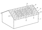
図1において、1は住宅等の建物、2は建物1の屋根である。この屋根2は、図4,図7に示した傾斜する野地板3と、図4,図5に示したように野地板3上に配設された複数のパネル支持レール4及び複数の太陽電池パネル5を有する。この太陽電池パネル5の上縁部及び下縁部には図5に示したように上下縁部及び端面に跨る断面コ字状のシール材5a,5bがそれぞれ取り付けられている。
In FIG. 1, 1 is a building such as a house, and 2 is a roof of the building 1. The
また、屋根2は、野地板3の屋根面3a上に図7の様に配設された屋根材としての平瓦(図1,図6参照)6を有する。
Moreover, the
そして、複数の平瓦6は、図6に示したように縦横に配列されていると共に、横方向に
おいてずれた状態で配列されている。しかも、縦方向に配列された複数の平瓦6は、上縁部に上側の平瓦6の下縁部が載せられ、且つ下縁部が下側の平瓦6の上縁部上に載せられている。これにより、平瓦6は野地板3の屋根面3aに対して所定角度αを為している。この状態で各平瓦6は野地板3上に取り付けられている。
The plurality of
尚、図示は省略したが野地板3上には防水下地材が設けられる。また、複数のパネル支持レール4は、横方向に向けて配設されていると共に、縦方向(野地板3の傾斜方向)に間隔をおいて配設されている。
Although not shown, a waterproof base material is provided on the
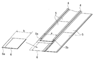
パネル支持レール4は、図5に示したように、野地板3上に図示しない木ねじ又は釘等の固定手段で固定されたベース板部4aと、このベース板部4aの幅方向中央から鉛直方向に向けて上方に突出する起立板部4bと、この起立板部4bの中間部の一側面に突設された上下一対の保持板部4c,4dを有する。尚、ベース板部4aと起立板部4bは予め傾斜した状態で形成されている。
As shown in FIG. 5, the
この起立板部4b及び保持板部4c,4dはベース板部4aの両端まで延びている。そして、保持板部4c,4d間には、軒側に向けて開口し且つ保持板部4c,4dの長手方向両端まで延びるパネル保持溝(軒側開口パネル保持溝)7が形成されている。
The
また、パネル支持レール4は、起立板部4bの上端部に保持板部4c,4dと同方向に向けて折曲することにより形成された保持板部4eと、保持板部4eの先端から上方に向けて折曲された当て板部4fと、当て板部4fの上端から保持板部4eとは反対側に向けて折曲された保持板部4gを有する。この保持板部4e,4g間には、棟側に向けて開口し且つ保持板部4e,4gの両端まで延びるパネル保持溝(棟側開口パネル保持溝)8が形成されている。
The
このように各パネル支持レール4には、棟側に開口するパネル保持溝8及び軒側に開口するパネル保持溝7が上下に間隔を置いて形成されている。そして、パネル支持レール4,4間に配設された各太陽電池パネル5は、上縁部のシール材5aが上側のパネル支持レール4のパネル保持溝7に長手方向にスライド調整可能に嵌合保持され、下縁部のシール材5bが下側のパネル支持レール4のパネル保持溝8に長手方向にスライド調整可能に嵌合保持されている。これにより、太陽電池パネル5は、屋根面3aに対して所定角度αをなすようにパネル支持レール4,4に保持されている。
As described above, each
また、図8に示したように、パネル支持レール4,4の取り付けピッチ(野地板3の傾斜方向の取り付け間隔)aは、平瓦6の縦方向(傾斜方向)の長さ(寸法)bと同じ長さに形成されている。しかも、パネル支持レール4,4の横方向の両端部間には、隣接する平瓦6が太陽電池パネル5に端部に傾斜方向で略一致するように配設されている。
Further, as shown in FIG. 8, the mounting pitch of
従って、隣接する平瓦6と太陽電池パネル5の対向端部の合わせが容易で、この合わせ部の防水処理も容易となる。しかも、太陽電池パネル5の縦方向(屋根面3aの傾斜方向)における外観を平瓦6の縦方向の外観に似せることができる。
Therefore, it is easy to match the opposed end portions of the adjacent
この場合、平瓦(屋根材)6及び太陽電池パネル5の傾斜角度を同じ傾斜角度αにして、隣接する平瓦6及び太陽電池パネル5の対向端部同士を互いに化粧材を介して接合することにより、隣接する平瓦(屋根材)6及び太陽電池パネル5の対向端部同士の合わせ及び防水処理が容易となる。
In this case, the flat tile (roof material) 6 and the
しかも、平瓦6の傾斜方向の長さaと支持レール4,4の取り付けピッチを同じにして、横方向において隣接する平瓦6と太陽電池パネル5の側部同士を合わせることで、太陽
電池パネル5の外観と平瓦6の外観を更に似せることができる。
In addition, the length a of the
また、太陽電池パネル5の屋根面3aに対する傾斜角度を平瓦6の屋根面3aに対する傾斜角度と同じ所定角度αにすることで、太陽電池パネル5の外観と平瓦6の外観をより更に似せることができる。
Moreover, the external appearance of the
尚、太陽電池パネル5の横行方向の長さ(寸法)は、平瓦6の横方向の長さ(寸法)の略2倍の長さに形成されている。
[変形例]
上述した実施例では、太陽電池パネル5の横方向の長さを平瓦6の横方向の長さの2倍とした例を示したが、必ずしもこれに限定されるものではない。例えば、図9に示したように太陽電池パネル5の横方向の長さは、平瓦6の横方向の長さと同じ長さ又は2倍の長さに形成しても良いし、また3倍以上の長さに形成することもできる。この場合、屋根材としての平瓦6と太陽電池パネル5の横方向の端部を化粧材で覆うことで、横方向についても平瓦(屋根材)6に近い外観にできる。
In addition, the length (dimension) of the horizontal direction of the
[Modification]
In the above-described embodiment, the example in which the lateral length of the
また、端部防水処理の為、平瓦(屋根材)6との嵌合部より太陽電池パネル5側に端部を持ってくる場合には、支持レール4の全長をその分短くする。
Further, when the end portion is brought closer to the
更に、パネル支持レール4の長さは、平瓦6の横方向の長さと同じものから数倍の長さのものを複数用意しておくことで、特に2倍,4倍等偶数倍の長さのものを複数用意しておくことで、太陽電池パネル5を屋根面3aに取り付ける施工時に、パネル支持レール4のカット作業を無くすことができる。
Furthermore, the length of the
以上説明したように、この発明の実施の形態の太陽電池パネル設置構造においては、建物1の屋根面3a上に太陽電池パネル5を取り付けると共に、複数の屋根材(平瓦6)を前記太陽電池パネル5の周囲に位置させて縦横に前記屋根面3a上に並設している。しかも、太陽電池パネル設置構造においては、互いに平行な少なくとも一対のパネル支持レール4,4を縦方向又は横方向に間隔をおいて前記屋根面3a上に取り付け、前記太陽電池パネル5の縦方向両端又は横方向両端に位置する縁部を前記一対のパネル支持レール4,4にそれぞれ保持させている。更に、前記太陽電池パネル5の縦横の長さを前記屋根材(平瓦6)の縦横の長さと略同じか数倍に設定して、前記太陽電池パネル5と前記屋根材(平瓦6)の縁部を縦横において整列させている。
As described above, in the solar cell panel installation structure according to the embodiment of the present invention, the
尚、上述した実施例では複数のパネル支持レール4を横方向に向けると共に縦方向に等ピッチ(平瓦6の縦方向寸法に略一致)で配列しているが、パネル支持レール4を縦方向に向けると共に横方向に等ピッチ(平瓦6の横方向寸法に略一致)で配列することもできる。 In the above-described embodiment, the plurality of panel support rails 4 are oriented in the horizontal direction and arranged in the vertical direction at an equal pitch (substantially coincident with the vertical dimension of the flat roof tile 6). And can be arranged at an equal pitch in the horizontal direction (substantially coincides with the horizontal dimension of the flat roof tile 6).
このような構成によれば、パネル支持レール4を用いて太陽電池パネル5を屋根面3aに取り付けているので、太陽電池パネル5を安価に屋根面3aに取り付けることができる。しかも、前記太陽電池パネル5の縦横の長さを前記屋根材(平瓦6)の縦横の長さと略同じか数倍に設定して、前記太陽電池パネル5と前記屋根材(平瓦6)の縁部を縦横において整列させているので、太陽電池パネル5を屋根全体の外観を損なうことなく屋根面3aに取り付けることができる。
According to such a structure, since the
また、この発明の実施の形態の太陽電池パネル設置構造においては、前記パネル支持レール4は長さが前記屋根材(平瓦6)の縁部の長さと同じものから数倍のものを複数用意しておいて、これらの複数の異なる長さのパネル支持レール4を組み合わせて前記太陽電池パネルを前記屋根面に取り付けている。 Moreover, in the solar cell panel installation structure of the embodiment of the present invention, a plurality of panel support rails 4 having the same length as the edge length of the roofing material (flat roof tile 6) to several times as many are prepared. The solar cell panel is attached to the roof surface by combining the panel support rails 4 having a plurality of different lengths.
この構成によれば、前記パネル支持レール4は長さが前記屋根材(平瓦6)の縁部の長さと同じものから数倍のものを複数用意しておいて、これらの複数の異なる長さのパネル支持レール4を組み合わせて前記太陽電池パネル5を前記屋根面3aに取り付けるようにしているので、屋根面3aにパネル支持レール4を取り付ける施工時においてパネル支持レールのカット作業を無くすことができる。
According to this configuration, a plurality of panel support rails 4 having a length that is the same as the length of the edge of the roofing material (flat tile 6) to several times as many are prepared, and the plurality of different lengths are prepared. Since the
更に、この発明の実施の形態の太陽電池パネル設置構造においては、互いに対向して長手方向に延びるパネル保持溝7,8を前記一対のパネル支持レール4,4にそれぞれ設け、前記対向するパネル保持溝7,8に前記太陽電池パネル5の前記縁部をそれぞれ嵌合保持させている。
Furthermore, in the solar cell panel installation structure according to the embodiment of the present invention, the pair of panel support rails 4, 4 are provided with
この構成によれば、パネル支持レール4,4に設けたパネル保持溝7,8に太陽電池パネル5の縁部を嵌合保持させているので、太陽電池パネル5を簡易に取り付けることができる。
According to this configuration, since the edge of the
また、この発明の実施の形態の太陽電池パネル設置構造においては、前記パネル支持レール4は横方向に向けられると共に縦方向に間隔をおいて複数本前記屋根面3a上に取り付けられ、前記パネル保持溝7,8は前記各パネル支持レール4に形成され且つ前記建物1の棟側に開口させられた棟側開口パネル保持溝(パネル保持溝8)及び前記建物1の軒側に開口させられた軒側開口パネル保持溝(パネル保持溝7)であるとともに、前記棟側開口パネル保持溝(パネル保持溝8)及び軒側開口パネル保持溝(パネル保持溝7)は上下に位置させられている。
In the solar cell panel installation structure according to the embodiment of the present invention, the panel support rails 4 are oriented in the horizontal direction and are mounted on the
この構成によれば、前記棟側開口パネル保持溝(パネル保持溝8)及び軒側開口パネル保持溝(パネル保持溝7)の上下位置を予め屋根材(平瓦6)の棟側及び軒側の取り付け高さに調整しておくことで、太陽電池パネル5を屋根面3aに対して屋根材(平瓦6)と同じ角度(α)で取り付けることができるので、太陽電池パネル5を屋根全体の外観を損なうことなく屋根面3aに取り付けることができる。
According to this configuration, the vertical positions of the ridge side opening panel holding groove (panel holding groove 8) and the eaves side opening panel holding groove (panel holding groove 7) are set in advance on the ridge side and the eave side of the roofing material (flat roof tile 6). Since the
以上、図面を参照して、本発明の実施の形態を詳述してきたが、具体的な構成は、この実施の形態に限らず、本発明の要旨を逸脱しない程度の設計的変更は、本発明に含まれる。 The embodiment of the present invention has been described in detail above with reference to the drawings. However, the specific configuration is not limited to this embodiment, and design changes that do not depart from the gist of the present invention are not limited to this embodiment. Included in the invention.
1…建物
3a…屋根面
4…パネル支持レール
5…太陽電池パネル
6…平瓦(屋根材)
7…パネル保持溝(軒側開口パネル保持溝)
8…パネル保持溝(棟側開口パネル保持溝)
DESCRIPTION OF SYMBOLS 1 ... Building 3a ...
7. Panel holding groove (eave side opening panel holding groove)
8 ... Panel holding groove (ridge side opening panel holding groove)
Claims (4)
互いに平行な少なくとも一対のパネル支持レールを縦方向又は横方向に間隔をおいて前記屋根面上に取り付け、前記太陽電池パネルの縦方向両端又は横方向両端に位置する縁部を前記一対のパネル支持レールにそれぞれ保持させると共に、前記太陽電池パネルの縦横の長さを前記屋根材の縦横の長さと略同じか数倍に設定して、前記太陽電池パネルと前記屋根材の縁部を縦横において整列させたことを特徴とする太陽電池パネル設置構造。 In the solar cell panel installation structure in which a solar cell panel is attached on the roof surface of the building, and a plurality of roof materials are positioned around the solar cell panel and arranged side by side on the roof surface vertically and horizontally.
At least a pair of panel support rails parallel to each other are mounted on the roof surface at intervals in the vertical direction or the horizontal direction, and edges positioned at both the vertical direction ends or the horizontal direction ends of the solar cell panel are supported by the pair of panel supports. The vertical and horizontal lengths of the solar cell panels are set to be approximately the same or several times the vertical and horizontal lengths of the roof material, and the edges of the solar cell panels and the roof material are aligned in the vertical and horizontal directions. A solar panel installation structure characterized by having been made.
The panel support rails are oriented in the horizontal direction and are mounted on the roof surface at intervals in the vertical direction, and the panel holding grooves are formed in the panel support rails and open to the ridge side of the building. The ridge side opening panel holding groove and the eave side opening panel holding groove opened to the eave side of the building, and the ridge side opening panel holding groove and the eave side opening panel holding groove are positioned vertically. The solar cell panel installation structure according to claim 3, wherein:
Priority Applications (1)
| Application Number | Priority Date | Filing Date | Title |
|---|---|---|---|
| JP2004316864A JP2006125107A (en) | 2004-10-29 | 2004-10-29 | Solar cell panel installing structure |
Applications Claiming Priority (1)
| Application Number | Priority Date | Filing Date | Title |
|---|---|---|---|
| JP2004316864A JP2006125107A (en) | 2004-10-29 | 2004-10-29 | Solar cell panel installing structure |
Publications (1)
| Publication Number | Publication Date |
|---|---|
| JP2006125107A true JP2006125107A (en) | 2006-05-18 |
Family
ID=36720107
Family Applications (1)
| Application Number | Title | Priority Date | Filing Date |
|---|---|---|---|
| JP2004316864A Pending JP2006125107A (en) | 2004-10-29 | 2004-10-29 | Solar cell panel installing structure |
Country Status (1)
| Country | Link |
|---|---|
| JP (1) | JP2006125107A (en) |
Cited By (4)
| Publication number | Priority date | Publication date | Assignee | Title |
|---|---|---|---|---|
| JP2008095281A (en) * | 2006-10-06 | 2008-04-24 | Yane Gijutsu Kenkyusho:Kk | Fixing member and fixing structure of solar-cell module |
| FR2944304A1 (en) * | 2009-04-10 | 2010-10-15 | Saint Gobain | Solar modules i.e. glass substrates, fixation unit for solar roof of building, has support surfaces comprising seal packings and arranged at level of side ends of each of cores to form U-shaped sections for receiving respective substrates |
| FR2963089A1 (en) * | 2010-07-22 | 2012-01-27 | Evasol | Structure for maintaining photovoltaic panels in position with respect to frame i.e. roof framing, in cover of building, has lower transverse housing prolonged in outer side by cupping surface prolonged under upper panel |
| JP2012154101A (en) * | 2011-01-26 | 2012-08-16 | Asahi Kasei Homes Co | Frame, connection frame, and support device |
-
2004
- 2004-10-29 JP JP2004316864A patent/JP2006125107A/en active Pending
Cited By (5)
| Publication number | Priority date | Publication date | Assignee | Title |
|---|---|---|---|---|
| JP2008095281A (en) * | 2006-10-06 | 2008-04-24 | Yane Gijutsu Kenkyusho:Kk | Fixing member and fixing structure of solar-cell module |
| JP4679482B2 (en) * | 2006-10-06 | 2011-04-27 | 株式会社屋根技術研究所 | Solar cell module fixing member and solar cell module fixing structure |
| FR2944304A1 (en) * | 2009-04-10 | 2010-10-15 | Saint Gobain | Solar modules i.e. glass substrates, fixation unit for solar roof of building, has support surfaces comprising seal packings and arranged at level of side ends of each of cores to form U-shaped sections for receiving respective substrates |
| FR2963089A1 (en) * | 2010-07-22 | 2012-01-27 | Evasol | Structure for maintaining photovoltaic panels in position with respect to frame i.e. roof framing, in cover of building, has lower transverse housing prolonged in outer side by cupping surface prolonged under upper panel |
| JP2012154101A (en) * | 2011-01-26 | 2012-08-16 | Asahi Kasei Homes Co | Frame, connection frame, and support device |
Similar Documents
| Publication | Publication Date | Title |
|---|---|---|
| JP4290750B2 (en) | Solar cell module fixing structure, solar cell module frame and fixing member | |
| MX2007010391A (en) | Roof cover or facade siding. | |
| JP2010261257A (en) | Structure for fixing solar cell module | |
| GB2466003A (en) | Securing A Solar Energy Collection Device As Part Of A Roof | |
| JP4785958B2 (en) | Solar power plant | |
| JPH10317619A (en) | Roof installed with rooftop equipment such as solar cell module | |
| JP2005264618A (en) | Solar roof | |
| JP2006125107A (en) | Solar cell panel installing structure | |
| JP3504109B2 (en) | Roof waterproof structure with a rooftop installation base | |
| JP2011144575A (en) | Structure of photovoltaic panel-installed roof, and method for constructing the same | |
| JPH10245952A (en) | Frame mounting metal piece of solar power generating panel | |
| JP6062671B2 (en) | Installation structure of roofed structures | |
| JPH10317598A (en) | Roof mounted with roof-top equipment such as solar battery module | |
| JP6218683B2 (en) | Solar roof and mount | |
| JP6804194B2 (en) | Solar power roof | |
| JP2006090082A (en) | Starter metal fittings and method of roofing plate roof materials | |
| JP5849013B2 (en) | Roof structure | |
| JPH10317620A (en) | Ventilation construction for roof installing rooftop equipment such as solar cell module | |
| JP6688067B2 (en) | Keraba cosmetics | |
| JP2011144574A (en) | Structure of photovoltaic panel-installed roof, and method for constructing the same | |
| JP2012087532A (en) | Attachment frame for mounting solar cell or the like on roofing | |
| JP7161324B2 (en) | Mounting structure | |
| JPH11343712A (en) | Installation structure of solar cell module in roof board | |
| JP2009155881A (en) | Finish structure of shed roof and method of installing finish structure of shed roof | |
| JP2002138638A (en) | Installation structure for solar cell module |