JP2006120056A - Database system and method thereof - Google Patents
Database system and method thereof Download PDFInfo
- Publication number
- JP2006120056A JP2006120056A JP2004309439A JP2004309439A JP2006120056A JP 2006120056 A JP2006120056 A JP 2006120056A JP 2004309439 A JP2004309439 A JP 2004309439A JP 2004309439 A JP2004309439 A JP 2004309439A JP 2006120056 A JP2006120056 A JP 2006120056A
- Authority
- JP
- Japan
- Prior art keywords
- node
- information
- search
- entry
- subtree
- Prior art date
- Legal status (The legal status is an assumption and is not a legal conclusion. Google has not performed a legal analysis and makes no representation as to the accuracy of the status listed.)
- Pending
Links
Images


Classifications
-
- G—PHYSICS
- G06—COMPUTING; CALCULATING OR COUNTING
- G06F—ELECTRIC DIGITAL DATA PROCESSING
- G06F17/00—Digital computing or data processing equipment or methods, specially adapted for specific functions
- G06F17/40—Data acquisition and logging
-
- G—PHYSICS
- G06—COMPUTING; CALCULATING OR COUNTING
- G06F—ELECTRIC DIGITAL DATA PROCESSING
- G06F16/00—Information retrieval; Database structures therefor; File system structures therefor
- G06F16/20—Information retrieval; Database structures therefor; File system structures therefor of structured data, e.g. relational data
- G06F16/28—Databases characterised by their database models, e.g. relational or object models
- G06F16/284—Relational databases
- G06F16/288—Entity relationship models
-
- G—PHYSICS
- G06—COMPUTING; CALCULATING OR COUNTING
- G06F—ELECTRIC DIGITAL DATA PROCESSING
- G06F16/00—Information retrieval; Database structures therefor; File system structures therefor
- G06F16/20—Information retrieval; Database structures therefor; File system structures therefor of structured data, e.g. relational data
- G06F16/22—Indexing; Data structures therefor; Storage structures
- G06F16/2228—Indexing structures
- G06F16/2246—Trees, e.g. B+trees
Landscapes
- Engineering & Computer Science (AREA)
- Theoretical Computer Science (AREA)
- Databases & Information Systems (AREA)
- Physics & Mathematics (AREA)
- General Engineering & Computer Science (AREA)
- Data Mining & Analysis (AREA)
- General Physics & Mathematics (AREA)
- Software Systems (AREA)
- Computer Hardware Design (AREA)
- Mathematical Physics (AREA)
- Information Retrieval, Db Structures And Fs Structures Therefor (AREA)
Abstract
Description
本発明は、データを記憶する方法及び記憶するデータ構造に関する。
より詳細には、相互に関連性を持った一連のデータを記憶する方法及び記憶するデータ構造に関する。
The present invention relates to a method for storing data and a data structure for storing.
More particularly, the present invention relates to a method for storing a series of data that are related to each other and a data structure to be stored.
関連するデータを記憶し、記憶されたこのようなデータを検索するために、リレーショナル・データベースと呼ばれる装置が用いられている。
また、例えば、非特許文献1および特許文献1,2は、関連するデータを記憶する方法、および、記憶されたこのようなデータを検索する方法を開示する。
しかしながら、リレーショナル・データベースにおいて、完成されたデータベースの構造(スキーマ)を変更することは、容易ではない。
また、これらの文献に開示されている方法では、データの記述内容が複雑になり、また、データの表記・格納方法が一意的ではない。
また、これらの文献に開示されている方法では、データベースが複数のサーバを用いて実現されているときに、これら複数のサーバ間における負荷分散が容易ではない。
Further, for example, Non-Patent
However, it is not easy to change the structure (schema) of a completed database in a relational database.
In addition, in the methods disclosed in these documents, the description contents of data are complicated, and the data notation / storage method is not unique.
Further, in the methods disclosed in these documents, when a database is realized using a plurality of servers, load distribution among the plurality of servers is not easy.
本発明は、上述のような背景からなされたものであり、データベースの構造を変更することなく、様々な種類の情報の追加が容易なデータベースシステムおよびその方法を提供することを目的とする。
また、本発明は、情報の記述が簡単で、情報の表記および格納方法が一意的なデータベースシステムおよびその方法を提供することを目的とする。
また、本発明は、データベースが複数の装置に分散されているときに、これら複数の装置間における負荷分散が容易なデータベースシステムおよびその方法を提供することを目的とする。
また、本発明は、このように登録された情報を検索するために適したデータベースシステムおよびその方法を提供することを目的とする。
The present invention has been made from the above background, and an object of the present invention is to provide a database system and method for easily adding various types of information without changing the structure of the database.
It is another object of the present invention to provide a database system and method for easily describing information and having a unique information notation and storage method.
It is another object of the present invention to provide a database system and method for easily distributing loads among a plurality of devices when the database is distributed to a plurality of devices.
Another object of the present invention is to provide a database system and method suitable for retrieving information registered in this way.
上記目的を達成するために、本発明にかかるデータベースシステムは、1つ以上の関連ノードと、1つ以上の見出ノードとを関連付けてディレクトリツリーの形式のデータベースとするデータベースシステムであって、前記関連ノードそれぞれは、1つ以上の前記見出ノードと関連付けられ、前記見出ノードそれぞれには1つ以上の情報が属し、前記関連付けられた前記関連ノードと前記見出ノードとの間それぞれに対しては、これらの間の関連を示す関連属性が定義され、前記関連ノードそれぞれの関連ノードエントリと、前記関連属性それぞれの関連属性エントリとを作成し、これらのエントリを、前記関連ノードと前記関連属性との関連に従って対応付けて、ディレクトリツリーを作成するディレクトリツリー作成手段と、前記見出ノードそれぞれに対応する情報を、前記作成された関連属性エントリに、前記見出ノードと前記関連属性との関連に従って対応付ける情報対応付手段とを有する。 In order to achieve the above object, a database system according to the present invention is a database system that associates one or more related nodes and one or more found nodes into a database in the form of a directory tree. Each associated node is associated with one or more of the found nodes, each of which finds one or more information, each between the associated associated node and the found node A related attribute indicating a relation between them is defined, and a related node entry for each of the related nodes and a related attribute entry for each of the related attributes are created, and these entries are connected to the related node and the related Directory tree creating means for creating a directory tree in association with each other in association with the attribute; The information corresponding to each de, the related attribute entry created in the above, and an information associating unit for associating in accordance with the relevant and the associated attributes and the topic nodes.
好適には、前記関連属性は、前記関連ノードと前記見出ノードとの間に定義される役割を示す。 Preferably, the related attribute indicates a role defined between the related node and the found node.
好適には、前記ディレクトリツリーは、1つ以上のサブツリーを含み、前記ディレクトリツリーおよび前記サブツリーそれぞれには、最上位のエントリが定義され、前記サブツリーそれぞれの最上位のエントリは、前記ディレクトリツリーおよび他の前記サブツリーのエントリのいずれかを参照し、前記ディレクトリツリーおよびサブツリーにおいて、前記関連ノードおよび前記見出ノードは、階層的に対応付けられる。 Preferably, the directory tree includes one or more subtrees, and each of the directory tree and the subtree has a top-level entry defined, and the top-level entry of each of the subtrees includes the directory tree and others. In the directory tree and the subtree, the related node and the found node are hierarchically associated with each other.
好適には、前記サブツリーそれぞれの最上位のエントリそれぞれと、これら最上位のエントリが参照する前記ディレクトリツリーまたは他の前記サブツリーに含まれるエントリとを対応付ける最上位エントリ対応付手段をさらに有する。 Preferably, there is further provided an uppermost entry association means for associating each uppermost entry of each of the subtrees with an entry included in the directory tree or other subtree referenced by the uppermost entry.
好適には、前記ディレクトリツリーおよび前記サブツリーのいずれかに従って、これらのディレクトリツリーのいずれかに含まれる見出ノードに対応する情報と、前記関連ノードに対応する情報と、前記見出ノードと前記関連ノードとの間に定義される役割とをそれぞれ記憶する1つ以上の第1のデータベース装置を有する。 Preferably, according to any of the directory tree and the sub-tree, information corresponding to a found node included in any of these directory trees, information corresponding to the related node, the found node and the related One or more first database devices each storing roles defined between nodes.
好適には、ある第1のデータベース装置に記憶された情報を、他の第1のデータベース装置に転送して記憶させる情報転送手段をさらに有する。 Preferably, the information processing device further includes information transfer means for transferring information stored in a certain first database device to the other first database device for storage.
好適には、前記情報転送手段は、前記第1のデータベース装置の動作状態に基づいて、ある第1のデータベース装置から、他の第1のデータベース装置に転送する情報を決める。 Preferably, the information transfer means determines information to be transferred from a certain first database device to another first database device based on an operating state of the first database device.
好適には、前記情報転送手段は、前記ディレクトリツリーまたは前記サブツリーに対するアクセス状態に基づいて、ある第1のデータベース装置から、他の第1のデータベース装置に転送する情報を決める。 Preferably, the information transfer means determines information to be transferred from one first database device to another first database device based on an access state to the directory tree or the subtree.
好適には、前記第1のデータベース装置の1つ以上に記憶された情報の複製を記憶する第2のデータベース装置をさらに有し、前記最上位エントリ対応付手段は、前記第1のデータベース装置の最上位エントリと、前記第1のデータベース装置に記憶された情報の複製を記憶する前記第2のデータベース装置とをさらに対応付ける。 Preferably, the information processing apparatus further includes a second database device that stores a copy of information stored in one or more of the first database devices, and the highest-level entry association unit includes the first database device. The top entry is further associated with the second database device that stores a copy of the information stored in the first database device.
好適には、前記ディレクトリツリーおよび前記サブツリーそれぞれには、さらに1つ以上の前記サブツリーが含まれることがあり、前記ディレクトリツリーおよび前記サブツリーそれぞれから、さらに前記サブツリーを作成するサブツリー作成手段をさらに有する。 Preferably, each of the directory tree and the subtree may further include one or more subtrees, and further includes subtree creation means for creating the subtree from each of the directory tree and the subtree.
好適には、前記ディレクトリツリーおよび前記サブツリーそれぞれには、前記関連ノードおよび見出しノードの分類に用いられる分類情報が定義され、前記前記ディレクトリツリーおよび前記サブツリーそれぞれと、これらのディレクトリツリーそれぞれに定義された分類情報とを対応付ける分類情報対応付手段をさらに有する。 Preferably, classification information used for classification of the related node and the header node is defined in each of the directory tree and the subtree, and each of the directory tree and the subtree and each of these directory trees are defined. It further has classification information association means for associating the classification information.
好適には、前記記憶された見出ノードに対応する情報を検索する検索装置をさらに有する。 Preferably, the apparatus further includes a search device for searching for information corresponding to the stored found node.
好適には、前記検索装置は、検索条件を受け入れる検索条件受入手段と、前記受け入れられた検索条件に対応する前記分類情報と対応付けられた前記ディレクトリツリーまたは前記サブツリーを検索するディレクトリツリー検索手段と、前記検索の結果として得られたディレクトリツリーに含まれる見出ノードに対応する情報を検索する情報検索手段とを有する。 Preferably, the search device includes search condition accepting means for accepting a search condition, and directory tree search means for searching the directory tree or the subtree associated with the classification information corresponding to the accepted search condition. And information search means for searching for information corresponding to the found node included in the directory tree obtained as a result of the search.
また、本発明にかかる情報管理方法は、1つ以上の関連ノードと、1つ以上の見出ノードとを関連付けてディレクトリツリーのデータベースにおける情報管理方法であって、前記関連ノードそれぞれは、1つ以上の前記見出ノードと関連付けられ、前記見出ノードそれぞれには1つ以上の情報が属し、前記関連付けられた前記関連ノードと前記見出ノードとの間それぞれに対しては、これらの間の関連を示す関連属性が定義され、前記関連ノードそれぞれの関連ノードエントリと、前記関連属性それぞれの関連属性エントリとを作成し、これらのエントリを、前記関連ノードと前記関連属性との関連に従って対応付けて、ディレクトリツリーを作成し、前記見出ノードそれぞれに対応する情報を、前記作成された関連属性エントリに、前記見出ノードと前記関連属性との関連に従って対応付ける。 The information management method according to the present invention is an information management method in a database of a directory tree in which one or more related nodes and one or more found nodes are associated with each other, and each of the related nodes is one. Each of the found nodes is associated with one or more pieces of information, and for each of the associated related node and the found node, between them, A relation attribute indicating a relation is defined, and a relation node entry for each of the relation nodes and a relation attribute entry for each of the relation attributes are created, and these entries are mapped according to the relation between the relation node and the relation attribute. A directory tree is created, and information corresponding to each of the found nodes is added to the created related attribute entry. Associating in accordance with the relevant and the associated attributes and nodes.
好適には、前記ディレクトリツリーは、1つ以上のサブツリーを含み、前記ディレクトリツリーおよび前記サブツリーそれぞれには、最上位のエントリが定義され、前記サブツリーそれぞれの最上位のエントリは、前記ディレクトリツリーおよび他の前記サブツリーのエントリのいずれかを参照し、前記ディレクトリツリーおよび前記サブツリーそれぞれには、さらに1つ以上の前記サブツリーが含まれることがあり、前記ディレクトリツリーおよび前記サブツリーそれぞれから、さらに前記サブツリーを作成する。 Preferably, the directory tree includes one or more subtrees, and each of the directory tree and the subtree has a top-level entry defined, and the top-level entry of each of the subtrees includes the directory tree and others. The directory tree and each of the subtrees may further include one or more of the subtrees, and further create the subtree from each of the directory tree and the subtree. To do.
好適には、前記ディレクトリツリーは、1つ以上のサブツリーを含み、前記ディレクトリツリーおよび前記サブツリーそれぞれには、最上位のエントリが定義され、前記サブツリーそれぞれの最上位のエントリは、前記ディレクトリツリーおよび他の前記サブツリーのエントリのいずれかを参照し、前記ディレクトリツリーおよび前記サブツリーのいずれかに従って、これらのディレクトリツリーのいずれかに含まれる見出ノードに対応する情報と、前記関連ノードに対応する情報と、前記見出ノードと前記関連ノードとの間に定義される役割とをそれぞれ記憶し、前記記憶された見出ノードに対応する情報を検索する。 Preferably, the directory tree includes one or more subtrees, and each of the directory tree and the subtree has a top-level entry defined, and the top-level entry of each of the subtrees includes the directory tree and others. Information corresponding to the found node included in any of these directory trees, and information corresponding to the related nodes according to any of the directory tree and the subtree, and Each of the roles defined between the found node and the related node is stored, and information corresponding to the stored found node is retrieved.
好適には、検索条件を受け入れ、前記受け入れられた検索条件に対応する前記分類情報と対応付けられた前記ディレクトリツリーまたは前記サブツリーを検索し、前記検索の結果として得られたディレクトリツリーに含まれる見出ノードに対応する情報を検索する。 Preferably, a search condition is accepted, the directory tree or the subtree associated with the classification information corresponding to the accepted search condition is searched, and the directory tree obtained as a result of the search is searched. Search for information corresponding to the source node.
好適には、前記ディレクトリツリーおよび前記サブツリーのいずれかに従って、これらのディレクトリツリーのいずれかに含まれる見出ノードに対応する情報と、前記関連ノードに対応する情報と、前記見出ノードと前記関連ノードとの間に定義される役割とを、複数の第1のデータベース装置に記憶し、ある第1のデータベース装置に記憶された情報を、他の第1のデータベース装置に転送して記憶させる。 Preferably, according to any of the directory tree and the sub-tree, information corresponding to a found node included in any of these directory trees, information corresponding to the related node, the found node and the related The roles defined between the nodes are stored in a plurality of first database devices, and the information stored in a certain first database device is transferred to and stored in another first database device.
また、本発明にかかるプログラムは、コンピュータを含み、1つ以上の関連ノードと、1つ以上の見出ノードとを関連付けてディレクトリツリーのデータベースとするデータベースシステムのプログラムであって、前記関連ノードそれぞれは、1つ以上の前記見出ノードと関連付けられ、前記見出ノードそれぞれには1つ以上の情報が属し、前記関連付けられた前記関連ノードと前記見出ノードとの間それぞれに対しては、これらの間の関連を示す関連属性が定義され、前記関連ノードそれぞれの関連ノードエントリと、前記関連属性それぞれの関連属性エントリとを作成し、これらのエントリを、前記関連ノードと前記関連属性との関連に従って対応付けて、ディレクトリツリーを作成するステップと、前記見出ノードそれぞれに対応する情報を、前記作成された関連属性エントリに、前記見出ノードと前記関連属性との関連に従って対応付けるステップとをコンピュータに実行させる。 A program according to the present invention is a database system program including a computer and associating one or more related nodes with one or more found nodes as a directory tree database, Is associated with one or more of the find nodes, each of the find nodes to which one or more information belongs, and for each between the associated related node and the find node, A related attribute indicating a relationship between them is defined, and a related node entry for each of the related nodes and a related attribute entry for each of the related attributes are created, and these entries are assigned to the related node and the related attribute. Corresponding according to the association, creating a directory tree, and corresponding to each of the found nodes Distribution and the associated attribute entry created in the above, and a step of associating in accordance with the relevant and the associated attributes and the topic nodes to the computer.
本発明によれば、データベースの構造を変更することなく、様々な種類の情報の追加が容易なデータベースシステムおよびその方法を提供することができる。
また、本発明によれば、情報の記述が簡単で、情報の表記および格納方法が一意的なデータベースシステムおよびその方法を提供することができる。
また、本発明によれば、データベースが複数の装置に分散されているときに、これら複数の装置間における負荷分散が容易なデータベースシステムおよびその方法を提供することができる。
また、本発明によれば、このように登録された情報を検索するために適したデータベースシステムおよびその方法を提供することができる。
According to the present invention, it is possible to provide a database system and method for easily adding various types of information without changing the structure of the database.
Further, according to the present invention, it is possible to provide a database system and a method thereof in which the description of information is simple and the information notation and storage method is unique.
Further, according to the present invention, it is possible to provide a database system and method for easily distributing loads among a plurality of devices when the database is distributed to a plurality of devices.
In addition, according to the present invention, it is possible to provide a database system and method suitable for searching for information registered in this way.
[本発明がなされるに至った経緯]
本発明の理解を助けるために、まず、本発明がなされるに至った経緯を説明する。
様々な要素を含むデータを、効率的に収集し、それらのデータを記憶することが行われている。
記憶されたデータから、必要に応じてデータを読み出しこれらのデータを正確に再現することが望まれている。
一般に、直積集合A×Bの部分集合R⊆A×Bにおいて、順序対(a,b)∈Rに対して、aRbと表記すると、これは「aはbと関係Rを有する」ことを意味する。
簡単なデータの一例として、「作家シェークスピアは戯曲ハムレットを書いた。」を例にとる。
[Background to the Invention]
In order to help understanding of the present invention, first, the background to the present invention will be described.
Data including various elements is efficiently collected and stored.
It is desired to read out data from stored data as necessary and to accurately reproduce these data.
In general, in the subset R⊆A × B of the Cartesian product set A × B, when expressed as aRb with respect to the ordered pair (a, b) ∈R, this means that “a has relation R with b” To do.
As an example of simple data, “writer Shakespeare wrote drama Hamlet” is taken as an example.
これらのデータは2項関係にあるので、「作家シェークスピア」=a、R=作者−作品、b=「戯曲ハムレット」と置くことにより、「作家シェークスピアは戯曲ハムレットを書いた。」なるデータが、「aRb」と表記される。
これらのデータは、データベースに記憶する際に、「a」、「R」及び「b」として記憶され、データを読み出す場合にも一意に再現できる。
しかし、データの構成要素数が増えた場合は、すなわち2項関係ではなくn項関係になる場合には、これら関連性をもつ一連のデータはハイパーグラフ構造として表現され、処理は簡単ではない。
このため、一般にはn項関係を2項関係に分割して、それらの組合せとして表現し、データベースに記憶する手法がとられる。
Since these data are in a binary relationship, by placing “writer Shakespeare” = a, R = author-works, b = “drama Hamlet”, the data “writer Shakespeare wrote drama Hamlet” Indicated as “aRb”.
These data are stored as “a”, “R”, and “b” when stored in the database, and can be uniquely reproduced when data is read out.
However, when the number of data components increases, that is, when there is an n-term relationship instead of a binary relationship, a series of data having these relationships is expressed as a hypergraph structure, and processing is not easy.
For this reason, generally, a method is used in which n-term relationships are divided into binary relationships, expressed as combinations thereof, and stored in a database.
第1の例として「作家シェークスピアは戯曲ハムレットを英国で1600年頃書いた。」を例にとって説明する。
この例は4項関係を表したものであるが、2項関係に展開すると、4C2=6であるので表1に示すように6つの2項関係の組合せとして表現される。
As a first example, “writer Shakespeare wrote drama Hamlet in England around 1600” as an example.
This example represents a four-term relationship, but when expanded into a two-term relationship, 4C2 = 6, so it is expressed as a combination of six binary relationships as shown in Table 1.

すなわち、nが大きくなると、n項関係を表現するためにnC2なる数の2項関係の表現が必要となってしまう。 That is, when n increases, it is necessary to express nC2 binary relationships in order to express n-term relationships.
さらに、第2の例として「作家シェークスピアは戯曲十二夜を1600年頃書いた。」を例として取り2項関係の組合せで表現すると、3項関係すなわちn=3であるので、3C2=3となり、表2に示すようになる。 Furthermore, as a second example, “writer Shakespeare wrote the drama Twelve Nights around 1600.” As an example, it is expressed by a combination of binary relations, so that the ternary relation, that is, n = 3, 3C2 = 3. As shown in Table 2.
ここで、第1の例の情報と第2の例の情報とが同じデータベースに記憶されている場合、「作家シェークスピア」−「作者−創作年代」−「1600年頃」からなる同一の2項関係が記憶されるという問題が起こる。
また、上記第1及び第2の例として示された2項関係のうち、どれを組み合わせて元の情報を再現すればよいか判断できないという問題も生じる。
これらは2項関係毎に識別子を付ければ解消される問題であるが、データ構造や処理が煩雑になるという欠点がある。
Here, when the information of the first example and the information of the second example are stored in the same database, the same binary relation consisting of “writer Shakespeare” — “author—creating age” — “around 1600” The problem of being remembered.
Further, there arises a problem that it is impossible to determine which of the binary relations shown as the first and second examples is combined to reproduce the original information.
These are problems that can be solved by adding an identifier for each binary relationship, but have the disadvantage that the data structure and processing become complicated.
2項以上のデータ構成要素を有するデータを記憶する方法としては、リレーショナル・データベースによる記憶方法が知られている。
これは、データ項目名(データ属性)が列に割り当てられたテーブルを定義・作成し、具体的なデータをテーブルの行に順次入力していくものである。
As a method for storing data having two or more data components, a storage method using a relational database is known.
In this method, a table in which data item names (data attributes) are assigned to columns is defined and created, and specific data is sequentially input to the rows of the table.
「作家シェークスピアは戯曲ハムレットを英国で1600年頃書いた。」を例にとって説明する。
データ項目名としては、(1)「誰が」、(2)「何を」、(3)「何時」、(4)「どこで」、(5)「何故」、(6)「どのように」を指定することができる。
そしてこれらのデータ項目に対応して、(1)「作家シェークスピア」、(2)「戯曲ハムレット」、(3)「1600年頃」、(4)「英国」、(5)「(ブランク)」、(6)「書いた」のデータを記憶することができる。
“The writer Shakespeare wrote drama Hamlet in England around 1600,” explains.
Data item names include (1) “who”, (2) “what”, (3) “what”, (4) “where”, (5) “why”, (6) “how” Can be specified.
Corresponding to these data items, (1) “Artist Shakespeare”, (2) “Drama Hamlet”, (3) “About 1600”, (4) “UK”, (5) “(Blank)”, (6) “Written” data can be stored.
しかしながら、この方法では、次のような問題が生じる。
(1)データ項目名を、取得したデータに合わせて、後から追加することが簡単にはできない。定型の構成要素からなるデータの場合には、問題にはならないが、様々な構成要素を含むデータを入力する場合には、構成要素が増加するたびに、データ項目名を追加するためのスキーマの変更が必要となる。スキーマの変更はオンラインでデータの入力時には一般に困難である。
(2)後から追加することが簡単にはできないために、最初のデータベース構築時に、最大限のデータ項目数を挙げて、スキーマを構築することが考えられる。しかし入力する可能性の低いデータに対しても、データ項目としてスキーマを構築することは、メモリの使用効率が低くならざるを得ない。
However, this method has the following problems.
(1) The data item name cannot be easily added later in accordance with the acquired data. In the case of data consisting of standard components, there is no problem. However, when data including various components is entered, the schema for adding data item names each time the component increases. Changes are required. Schema changes are generally difficult when entering data online.
(2) Since it is not easy to add later, it is conceivable to construct a schema with the maximum number of data items at the time of the first database construction. However, even for data that is unlikely to be input, building a schema as a data item inevitably reduces the memory usage efficiency.
このような問題を解決するために、従来の関係データモデルに代わるモデルとして、英国「Lazy Software」社による「Associative Model of Data(データ関連モデル)」法によるデータ記憶方法が提案されている。
このデータモデルでは情報を事物と事物間の関連性と見なし、この関連性を「Source-Verb-Target」構文で表現している。
これによれば、上記のリレーショナル・データベースによる記憶方法で生じる問題の幾つかは解消される。
しかし、複雑なデータ関係を取扱う場合には、データ間の関係の表現方法が、複雑となり直感的でないこと、及び2分木的な形式を用いてn項関係を表現するため表現が一意に定まらず、データベースにデータを記憶する際に、作業者の任意にデータの構造を変えることができるために、データをデータベースから読取り再現する場合に、正確に入力情報を再現できない場合が発生するという問題がある。
In order to solve such problems, a data storage method based on the “Associative Model of Data” method by the UK “Lazy Software” company has been proposed as a model to replace the conventional relational data model.
In this data model, information is regarded as a relationship between things, and this relationship is expressed in a “Source-Verb-Target” syntax.
This eliminates some of the problems that arise with the relational database storage method described above.
However, when dealing with complex data relationships, the method of expressing the relationship between data is complicated and not intuitive, and the n-ary relationship is expressed using a binary tree-like form, so the expression is uniquely determined. First, when storing data in the database, the structure of the data can be arbitrarily changed by the operator, so when data is read from the database and reproduced, the input information may not be reproduced accurately. There is.
上記のように、従来、相互に関係のある複数のデータを記憶する方法としては、リレーショナル・データベースが知られていた。
これは、記憶しようとするデータ項目を予め定めておき、データ項目に該当するデータを記憶するものである。
データの関係が見易いという利点はあるもの、一旦構成されたデータベースのデータ項目を追加すること、すなわち、一旦構成されたデータベースの構造(スキーマ)を変更することは簡単ではない。
また後から追加したデータ項目に対応するデータは、従前から記憶されているデータに対して、空白エリアが生じメモリの使用効率が悪くなるという問題が生じている。
これに対して、Lazy Software社が提唱しているデータ関連モデルでは、データ項目数を追加する場合の困難さ、及びメモリの使用効率の低下といった問題は解決されるものの、データの記述内容が複雑になりデータ構造を見ても直感的ではなく、データの表記・記憶方法が一意的でないといった別の問題が生じる。
As described above, conventionally, a relational database has been known as a method of storing a plurality of mutually related data.
In this method, data items to be stored are determined in advance, and data corresponding to the data items are stored.
Although there is an advantage that the relation of data is easy to see, it is not easy to add a data item of the database once configured, that is, to change the structure (schema) of the database once configured.
Further, the data corresponding to the data items added later has a problem in that the use efficiency of the memory is deteriorated due to a blank area with respect to the data stored previously.
On the other hand, the data-related model proposed by Lazy Software solves the problems such as difficulty in adding the number of data items and reduced memory usage efficiency, but the description content of the data is complicated. However, it is not intuitive to look at the data structure, and another problem arises that the data notation / storage method is not unique.
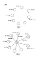
本発明では、見出ノード群と各ノード間の関連性を示すエッジ群から構成される関連性ネットワーク型データに対して、関連性(エッジ)を新たに関連ノード(以下、本願明細書では「Aノード」と呼ぶ。)とし、当該Aノードと関連性のある見出ノード(以下、本願明細書では「Tノード」と呼ぶ。)がその関連において果たす役割(以下、本願明細書では「関連性役割」と呼ぶ。)を属性とするエッジから成るデータモデルを定義する(図1)。
このモデルに従って変換されたデータ構造から、1つのAノードとTノード、及びその間の関連性役割を基本構成要素として抽出し、これらを表3に示すようにリレーショナル・データベースにおいて定義される関連性役割テーブル(以下、本願明細書では「ARテーブル」と呼ぶ。)の行(レコード)に対応付け、リレーショナル・データベース管理システムにより記憶・管理する方法を実現する。
In the present invention, with respect to the relevance network type data composed of the found node group and the edge group indicating the relevance between each node, the relevance (edge) is newly added to the related node (hereinafter referred to as “ A node that is related to the A node (hereinafter referred to as “T node” in the present specification) plays a role in the relationship (hereinafter referred to as “related” in this specification). A data model consisting of edges having the attribute “Gender role” is defined (FIG. 1).
From the data structure converted according to this model, one A node and T node, and the relationship roles between them are extracted as basic components, and these are defined as relationship roles defined in the relational database as shown in Table 3. A method of storing and managing a table (hereinafter referred to as “AR table” in the present specification) in association with a row (record) in a relational database management system is realized.
これにより、あるデータ(見出ノード)に関する新たな属性情報を別の関連性データとして定義し、それに対応するAノード、Tノード及びノード間のエッジの組合せ(すなわち、本発明のデータモデルにおける基本構成要素)を用いてARテーブルの行に対応付けられるデータとして表現すれば、既存のテーブル構造(データベース・スキーマ)を変更することなく新たな属性情報の追加が可能となる。
さらに、Aノード及びTノードにそれぞれ一意に同定できる識別子を付与し、各識別子に対して、ノードの属性型を表わすノードタイプと、属性値すなわちノードの具体的な内容を表わすノード名を有する識別子テーブル(以下、本願明細書では「IDテーブル」と呼ぶ。)を定義する(表5)。
As a result, new attribute information relating to a certain data (finding node) is defined as another relevance data, and the corresponding A node, T node, and edge combination between nodes (that is, the basic in the data model of the present invention) If it is expressed as data associated with a row of the AR table using the component), new attribute information can be added without changing the existing table structure (database schema).
Further, an identifier that can be uniquely identified is assigned to each of the A node and the T node, and an identifier having a node type that represents the attribute type of the node and a node name that represents an attribute value, that is, a specific content of the node, for each identifier. A table (hereinafter referred to as “ID table” in the present specification) is defined (Table 5).
これらのデータを、上記ARテーブルと同様に、リレーショナル・データベース管理システムにより記憶・管理する。
また、あるAノードにより示される関連性のもつ意味を具体的に記述するデータとして1つのTノードを新しく設け、これら2つのノードを「具象化」という予め定義された関連性役割で関連付ける。
当該Tノードと、別のAノードに関して同様に新しく設けられたTノードとの間での関連性を定義・記述することにより、元の2つのAノードにより示される関連性の間に存在する関係を表現することができる。
These data are stored and managed by the relational database management system in the same manner as the AR table.
Also, one T node is newly provided as data that specifically describes the meaning of the relationship indicated by a certain A node, and these two nodes are associated with a predefined relationship role of “reification”.
A relationship that exists between the relationships indicated by the original two A nodes by defining and describing the relationship between the T node and another newly established T node for another A node as well Can be expressed.
Aノードのもつ意味を記述するために特に導入された関連性役割「具象化」により関連付けられるTノードは、上記のARテーブルにより記憶・管理できる。
これらIDテーブル及びARテーブルを用いて各ノードを管理することにより、AノードとTノードの関連性だけでなく、AノードとAノードの関連性についても表記可能となるデータの表現方法を実現する。
The T node related by the relevance role “reification” introduced specifically for describing the meaning of the A node can be stored and managed by the AR table.
By managing each node using these ID table and AR table, a data representation method is realized that allows not only the relationship between the A node and the T node, but also the relationship between the A node and the A node. .
一般に、一つの共通の関連性を有するn個のデータからなるデータ集合について、2項関係で表現すると、nC2個のデータの組が必要となるが、本願発明によれば、n個のデータの組でよい。
言い換えると一つの共通の関連性を有するn個の要素を持つデータ集合について(図2、(a))、これらのデータをデータベースに記憶する場合に、当該データ集合に共通するノード(Aノード)を新たに1つ設け、次に各要素毎にその関連性役割を定義する(図2、(b))。
これにより、「Aノード」、「Tノード」及び「関連性役割」を一組のデータとして定義すれば、本願発明のデータ構造は構築できる(表4)。
In general, when a data set composed of n pieces of data having one common relationship is expressed by a binary relation, a set of nC2 pieces of data is required. A pair is sufficient.
In other words, for a data set having n elements having one common relationship (FIG. 2, (a)), when these data are stored in the database, a node common to the data set (A node) Is newly provided, and then the relevance role is defined for each element (FIG. 2, (b)).
Thus, if the “A node”, “T node”, and “relevance role” are defined as a set of data, the data structure of the present invention can be constructed (Table 4).
図2(b)及び表4で使用されている「A1」はAノードに付与された識別子であり、別の識別子「T1」〜「Tn」が付与された一群のデータ(Tノード)が何等かの共通の関連性を有していることを示すものである。
Aノードに付与された識別子が異なれば、それらの一連のデータは別の意味で何等かの共通の関連性を有していることになる。
さらに、識別子が付与されたAノード及びTノードに対して、表5に示すようにノードタイプとノード名をデータ属性としてもつIDテーブルを作成する。
“A1” used in FIG. 2B and Table 4 is an identifier assigned to the A node, and what is a group of data (T node) to which different identifiers “T1” to “Tn” are assigned? This indicates that they have a common relationship.
If the identifiers assigned to the A nodes are different, the series of data has some common relationship in another sense.
Further, as shown in Table 5, an ID table having a node type and a node name as data attributes is created for the A node and T node to which the identifier is assigned.
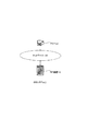
また、TノードT1とT2がAノードA1により関連付けられ、TノードT1とT3がAノードA2により関連付けられる関連性ネットワーク型データに対し(図3、(a))、AノードA1が示す関連性の意味を具体的に記述するTノード(識別子T11)を新たに設け、「具象化」という予め定義された関連性役割でA1と関連付ける。
同様に、AノードA2と新たなTノードT12を関連性役割「具象化」で関連付け、これら2つのTノードT11とT12との間にある関連性を、AノードA11を用いて定義する(図3、(b))。
これにより、元の2つのAノードA1とA2の間の関係が、表6に示すようなARテーブルを使って表現できる。
In addition, for the relevance network type data in which the T nodes T1 and T2 are associated by the A node A1 and the T nodes T1 and T3 are associated by the A node A2 (FIG. 3, (a)), A T node (identifier T11) that specifically describes the meaning of is newly provided and associated with A1 with a predefined relevance role of “reification”.
Similarly, the A node A2 and the new T node T12 are associated with the relationship role “reification”, and the relationship between these two T nodes T11 and T12 is defined using the A node A11 (see FIG. 3, (b)).
Thereby, the relationship between the original two A nodes A1 and A2 can be expressed using an AR table as shown in Table 6.
[データ記憶方法・データ構造]
以下、本発明におけるデータ記憶方法およびデータ構造を説明する。
具体例として、「作家シェークスピアは戯曲ハムレットを英国で1600年頃書いた。」を第1のデータとして説明する。
これらの情報は、(1)「作家シェークスピア」、(2)「戯曲ハムレット」、(3)「1600年頃」、(4)「英国」の要素をもつ4項関係を表したものである。
2項関係に分割してデータの関係を表現すると、4C2=6であるので以下の表7に示す様に6個の組合せとして表現される。
[Data storage method / data structure]
The data storage method and data structure in the present invention will be described below.
As a specific example, “writer Shakespeare wrote drama Hamlet in England around 1600” is explained as the first data.
This information represents a four-term relationship with the elements of (1) “writer Shakespeare”, (2) “drama Hamlet”, (3) “around 1600”, and (4) “UK”.
When the data relationship is expressed by being divided into binary relations, 4C2 = 6, so it is expressed as 6 combinations as shown in Table 7 below.
本願発明に従って、これらの情報を変換する。先ず第1番目のデータについて変換する。
見出ノード1にある「作家シェークスピア」は、この情報において「作者」であることを示しているので、「作家」と「シェークスピア」とに分けて、「シェークスピア」をTノード、「作者」を関連性役割とする。また、後述するように、「作家」をTノードのノードタイプとする。
また関連性を示すエッジ「作者−作品」については、上記の一連の情報が同じグループであることを示すために「ハムレット著作について」としてAノードを設ける。
「ハムレット著作について」のデータは、一連の情報が同じグループであることを示すために用いるので、他のグループの情報との識別ができるものであれば、他の表現でもかまわない。
These pieces of information are converted in accordance with the present invention. First, the first data is converted.
The “writer Shakespeare” in the
For the edge “author-work” indicating relevance, an A node is provided as “about Hamlet work” to indicate that the series of information is the same group.
Since the data about “Hamlet's work” is used to indicate that a series of information belongs to the same group, other expressions may be used as long as they can be distinguished from information of other groups.
「Aノード」−「Tノード」−「関連性役割」の構造で記述すると、表8に示すようになる。 When described in the structure of “A node” − “T node” − “association role”, it is as shown in Table 8.
同様に見出ノード2にある「戯曲ハムレット」は、この情報において「作品」であることから、変換すると表9のようになる。
また、「戯曲」をTノードのノードタイプとする。
Similarly, “drama hamlet” in the
Also, “drama” is a node type of T node.
次に、第2番目のデータについて同様に変換すると、表10のようになる。 Next, when the second data is similarly converted, Table 10 is obtained.
ここで、「ハムレット著作について」「シェークスピア」「作者」の情報は、冗長なデータなので省略することができる。以下同様に全てのデータについて変換し、冗長なデータを削除すると表11のようになる。 Here, the information about “Hamlet's work”, “Shakespeare”, and “author” can be omitted because it is redundant data. Similarly, all data is converted and redundant data is deleted, as shown in Table 11.
従って、一つの共通の関連性を有する4個のデータからなるデータ集合について、2項関係で表現すると、4C2=6であるので6個のデータの組が必要となるが、本願発明によれば、4個のデータ組でよいことが分かる。
言い換えると、4個の要素を持つデータ集合について、これらのデータをデータベースに記憶する場合に、当該データ集合に共通するノード(Aノード)を新たに1つ設け、次に要素毎にその関連性役割を定義し、「Aノード」、「Tノード」及び「関連性役割」を一組のデータとして定義すれば、本願発明のデータ構造は構築できる。
ここで、Aノード「ハムレット著作について」に識別子「A1」を付与する。ノード識別子「A1」を共通にもつこれらのデータは、一つのグループに属することが分かる。
さらに、4つのTノード「シェークスピア」、「ハムレット」、「1600年頃」、「英国」に対して識別子「T11」〜「T14」をそれぞれ付与する。
これにより、第1の例から作成されるARテーブルは表12のようになる。
Therefore, if a data set composed of four data having one common relationship is expressed by a binary relation, since 4C2 = 6, six data sets are required. It can be seen that four data sets are sufficient.
In other words, when storing these data in a database for a data set having four elements, one new node (A node) common to the data set is provided, and then the relevance for each element is set. If a role is defined and “A node”, “T node” and “association role” are defined as a set of data, the data structure of the present invention can be constructed.
Here, the identifier “A1” is assigned to the A node “About Hamlet Works”. It can be seen that these data having the node identifier “A1” in common belong to one group.
Further, identifiers “T11” to “T14” are assigned to the four T nodes “Shakespeare”, “Hamlet”, “around 1600”, and “UK”, respectively.
Thus, the AR table created from the first example is as shown in Table 12.
また、「ハムレット著作について」を示すAノード(識別子A1)のノードタイプを「著作関連情報」とし、識別子T11〜T14が付与されたTノードのノードタイプをそれぞれ「作家」、「戯曲」、「年代」、「国」とすることにより、表13に示すようなIDテーブルが作成される。 In addition, the node type of the A node (identifier A1) indicating “about Hamlet's work” is set as “work related information”, and the node types of the T nodes assigned with the identifiers T11 to T14 are “writer”, “drama”, “ By setting “year” and “country”, an ID table as shown in Table 13 is created.
さらに、第2のデータとして「戯曲ハムレットを原作とする日本語翻訳版が2003年2月に○○出版社から出版された。」の情報を例にとる。
これらの情報を本願発明に従ってデータを構成すると次のようになる。ここで一連の情報要素に共通するAノードは「ハムレット日本語訳について」とし、識別子「A2」を付与すると表14のようになる。
Furthermore, as the second data, the information “Japanese translation version based on drama Hamlet was published by XX publisher in February 2003” is taken as an example.
When these pieces of information are constructed in accordance with the present invention, data is as follows. Here, the A node common to a series of information elements is “about Hamlet Japanese translation”, and the identifier “A2” is given as shown in Table 14.
原作であるハムレットには既に識別子「T12」が付けられているので、翻訳版ハムレットに「T22」、出版日及び出版社に対してそれぞれ識別子「T23」、「T24」を付与すると、第2のデータに対するARテーブルは表15のようになる。 Since the original “Hamlet” has already been assigned the identifier “T12”, the identifier “T23” and “T24” are assigned to the translated version Hamlet and the publication date and publisher, respectively. Table 15 shows the AR table for data.
また、表16に示すIDテーブルが作成される。
これら第1及び第2のデータ、さらに同様のデータ変換処理が施された他のデータも同じデータベースに記憶されるので、最終的に表17及び表18に示すようなARテーブル及びIDテーブルが得られる。 Since these first and second data and other data subjected to the same data conversion process are also stored in the same database, the AR table and ID table as shown in Table 17 and Table 18 are finally obtained. It is done.
さらに、図4に示すように、識別子がA1及びA2であるAノードにより示される関連性のもつ意味を具体的に記述するためのTノードを設け、それぞれに識別子「T31」及び「T32」を付与し、ノードA1及びノードA2と関連性役割「具象化」で関連付ける。
これら2つの新たなTノードのノードタイプを「著作情報」とし、ノード名としてはそれぞれ「ハムレット著作について」及び「ハムレット日本語訳について」とする。
ノードT31とノードT32との関連性を示すAノードを、識別子A3としてさらに新しく設け、ノードタイプを「原作−翻訳情報」とする。
また、ここでの関連においてノードT31及びノードT32が果たす役割をそれぞれ「原作情報」、「翻訳情報」とする。以上の処理から、表19に示したARテーブル及び表20に示したIDテーブルが追加される。
Further, as shown in FIG. 4, T nodes for specifically describing the meaning of the relationship indicated by the A nodes whose identifiers are A1 and A2 are provided, and identifiers “T31” and “T32” are respectively provided. And associate with the node A1 and the node A2 by the relevance role “reification”.
The node type of these two new T-nodes is “Copyright information”, and the node names are “About Hamlet work” and “About Hamlet Japanese translation”, respectively.
An A node indicating the relationship between the node T31 and the node T32 is newly provided as an identifier A3, and the node type is “original work-translation information”.
Further, the roles played by the node T31 and the node T32 in the relation here are “original information” and “translation information”, respectively. From the above processing, the AR table shown in Table 19 and the ID table shown in Table 20 are added.
上記の第1及び第2のデータを、リレーショナル・データベースに直接記憶するためには、データ項目名として、新たに翻訳版としての「ハムレット」あるいは「○○出版社」などに対応する項目(データ属性)を追加する必要がある。これはデータベースのテーブル構造を変更することになるので簡単ではない。
本発明では、例に示した様に既存のARテーブルに対し行を追加することにより、異なるデータ属性を有する情報を複数の組として記憶することが可能である。
また、第1及び第2のデータを、Aノード、Tノード及び各ノード間の関連を示すエッジを用いて表現すると図4のようになる。
本発明では、こうした複雑な構造をもつデータを容易に表現するための方法とリレーショナル・データベースへの記憶・管理方法を提供している。
In order to directly store the above first and second data in the relational database, the data item name is a new item corresponding to “Hamlet” or “XX Publisher” (data). Attribute) must be added. This is not easy because it changes the table structure of the database.
In the present invention, it is possible to store information having different data attributes as a plurality of sets by adding rows to an existing AR table as shown in the example.
Further, when the first and second data are expressed using the A node, the T node, and an edge indicating the relation between the nodes, the result is as shown in FIG.
The present invention provides a method for easily expressing data having such a complicated structure and a method for storing and managing data in a relational database.
次に本願発明のデータベースから所望のデータを検索する場合について説明する。
以下に、ユーザが「作家シェークスピアの書いた戯曲ハムレットの日本語訳の出版社を知りたい」場合を例にとって説明する。
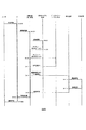
図5にそのフローチャートを示す。以下に図5のフローチャートの説明をする。
Next, a case where desired data is searched from the database of the present invention will be described.
The case where the user wants to know the publisher of the Japanese translation of the drama Hamlet written by writer Shakespeare will be described below as an example.
The flowchart is shown in FIG. The flowchart of FIG. 5 will be described below.
110:ユーザは検索条件を「作家」である「シェークスピア」の「戯曲」として入力する。
120:検索条件に合致する複数組のデータを収集する。
130:複数組検出された情報の中から、「戯曲」に対応する情報を順次表示する。
140:ユーザはこれらの中から所望の戯曲名、すなわち「ハムレット」を選択する。
150:「ハムレット」及び「翻訳版」を新たな条件として、データを検索する。
160:検索条件に合致する複数組データを収集する。
170:検出された複数組の中から「出版社」及び「出版日」に関するデータを順次表示する。
180:ユーザは所望の出版社を選択する。
110: The user inputs the search condition as “drama” of “shakespeare” which is “writer”.
120: Collect a plurality of sets of data that match the search conditions.
130: Information corresponding to “drama” is sequentially displayed from the information detected in plural sets.
140: The user selects a desired drama name, ie, “Hamlet”, from these.
150: Data is retrieved using “hamlet” and “translated version” as new conditions.
160: Collect multiple sets of data that match the search conditions.
170: Data related to “publisher” and “publishing date” are sequentially displayed from the detected plurality of sets.
180: The user selects a desired publisher.
以下、詳細に説明する。
ユーザは検索条件として、Tノードのノード名が「シェークスピア」であり、関連性役割が「作家」であることを入力し情報を検索する。
データベースの中でARテーブルを参照し、関連性役割が「作家」であるTノードの識別子を検出し、続いて、IDテーブルに記憶されているノード名属性を参照し、「シェークスピア」をノード名とするTノードに対応するAノード識別子が複数組検出される。
複数組検出されたAノード識別子をもつ情報の中から、別の検索条件、つまり関連性役割が「戯曲」となっているTノード識別子がARテーブルより選出される。
この識別子に基づいて、IDテーブルから対応する戯曲に関する情報が順次表示される。
Details will be described below.
As a search condition, the user searches for information by inputting that the node name of the T node is “Shakespeare” and the relevance role is “writer”.
The AR table is referenced in the database, the identifier of the T node whose relevance role is “writer” is detected, the node name attribute stored in the ID table is subsequently referenced, and “Shakespeare” is identified as the node name. A plurality of sets of A node identifiers corresponding to T nodes are detected.
From the information having a plurality of sets of detected A node identifiers, another search condition, that is, a T node identifier whose relevance role is “drama” is selected from the AR table.
Based on this identifier, information about the corresponding play is sequentially displayed from the ID table.
すなわち「ハムレット」、「じゃじゃ馬ならし」、「ベニスの商人」、「真夏の夜の夢」、「リア王」などの戯曲名が順次表示される。ユーザはこれらの中から所望の戯曲名、すなわち「ハムレット」を選択する。
引き続き、選択された「ハムレット」の識別子「T12」をキーとして、TノードIDに「ハムレット」の識別子を含み、かつ、関連性役割が「翻訳版」であるAノード識別子をARテーブルから検索する。
これにより、検索条件を満足するAノード識別子により関連付けられた複数組の情報が検出される。
検出された複数組の情報から、関連性役割として「出版社」及び「出版日」をもつTノードのノード名を、順次、IDテーブルを参照しながら表示する。
ユーザはその中から所望の出版社、すなわち最近「2003年2月」に戯曲ハムレットの翻訳版を出版した「○○出版社」を選択することができる。
In other words, the names of plays such as “Hamlet”, “Jajama tread”, “Venice merchant”, “Midsummer Night's Dream”, and “Lear King” are displayed in order. The user selects a desired drama name, that is, “Hamlet” from these.
Subsequently, using the identifier “T12” of the selected “Hamlet” as a key, the A node identifier including the identifier of “Hamlet” in the T node ID and having the relevance role “translated version” is searched from the AR table. .
Thereby, a plurality of sets of information associated with the A node identifier satisfying the search condition are detected.
From the detected plural sets of information, the node names of T nodes having “publishing company” and “publishing date” as relevance roles are sequentially displayed with reference to the ID table.
The user can select a desired publisher from among them, that is, “XX publisher” that recently published a translated version of the drama Hamlet in “February 2003”.
以上、図5に示した例は、検索例の一例として説明したものである。
つまり検索条件が多くなると、データベースの検索は、図5に示されているように2回に限定されるものではなく、所望の条件に応じて任意回数繰り返し行われることは言うまでもない。
また、ここで示した具体例においては、関連性役割として単一の属性が割り当てられているが、これに限定されるものではない。
すなわち、関連性役割に複数の属性をもたせることも可能である。上記の例では、関連性役割「戯曲」に対して「悲劇」、「喜劇」、「ロマンス劇」、「史劇」等のジャンルを追加して指定することにより、さらに詳細な関連性役割を定義することができる。
The example shown in FIG. 5 has been described as an example of a search example.
That is, as the search conditions increase, the database search is not limited to twice as shown in FIG. 5, but it goes without saying that the search is repeated any number of times according to the desired conditions.
In the specific example shown here, a single attribute is assigned as the relevance role, but the present invention is not limited to this.
That is, it is possible to give a plurality of attributes to the relevance role. In the above example, the relationship role “drama” is defined by adding more genres such as “tragedy”, “comedy”, “romance play”, “historic play”, etc. can do.
[本発明にかかるデータ記憶方法・データ構造の特徴]
以上説明したように、本発明にかかるデータ記憶方法およびデータ構造によると、現在、広く一般に用いられているリレーショナル・データベースのテーブル形式を用いて、3項以上の関係、一般にn項の相互に関連性をもった一連のデータの関係を表すハイパーグラフの構造を保持したまま、データを記憶及び管理することができる。
また、関連性ネットワーク型データをリレーショナル・データベースのテーブルに直接マッピングする方法では、3項以上の関係、一般にn項関係を表すデータを効率よく記憶・管理できないという問題が解決される。
[Features of Data Storage Method and Data Structure According to the Present Invention]
As described above, according to the data storage method and data structure according to the present invention, it is possible to use a relational database table format which is widely used at present, and to relate three or more terms, generally n terms. Data can be stored and managed while maintaining the structure of a hypergraph representing the relationship between a series of data having characteristics.
Further, the method of directly mapping the relevance network type data to the relational database table solves the problem that data representing three or more relations, generally data representing n-term relations, cannot be efficiently stored and managed.
また、既にデータベースに記憶されているデータに対して、属性情報を追加するなどの変更を行うにはリレーショナル・データベースのテーブル設計の変更が必要となり、柔軟性に欠けるとともに膨大な労力がかかるという問題が解決される。
さらに、同一のデータベース・スキーマの枠組みで、データに付与された識別子と関連性役割を用いて一連の関連性のもつ意味を記述することができる。
Also, in order to make changes such as adding attribute information to data already stored in the database, it is necessary to change the table design of the relational database, which is not flexible and requires a lot of effort. Is resolved.
Furthermore, in the same database schema framework, the meaning of a series of relationships can be described using identifiers and relationship roles assigned to data.
[第1のデータベース装置1]
以下、本発明にかかる第1のデータベースを説明する。
図6は、本発明にかかる第1のデータベースシステム(DBシステム)1の構成を例示する図である。
図6に示すように、本発明にかかる第1のDBシステム1は、データベース装置(DB装置)12が、必要に応じて、LAN、WANおよびインターネットなどのネットワーク100を介して、データ入力および検索のためなどに用いられるコンピュータ(PC)102と接続されて構成される。
なお、以下の説明においては、図4,図5および表7〜表20を参照して上述した本発明にかかるデータ記憶方法およびデータ構造の説明においてと、一部、用語が異なることがあるが、これらの説明の間で対応する用語は、実質的に同じである。
また、DBシステム1の説明については、以下の用語が、上述した本発明にかかるデータ記憶方法およびデータ構造の説明における用語よりも優先される。
また、以下の各図において、同様な構成部分には同じ符号が付される。
[First database device 1]
Hereinafter, the first database according to the present invention will be described.
FIG. 6 is a diagram illustrating the configuration of the first database system (DB system) 1 according to the present invention.
As shown in FIG. 6, in the
In the following description, terms may be partially different from those in the description of the data storage method and data structure according to the present invention described above with reference to FIGS. 4 and 5 and Tables 7 to 20. Corresponding terms between these descriptions are substantially the same.
In the description of the
In the following drawings, the same reference numerals are given to the same components.
[ハードウエア構成]
図7は、図6に示したDB装置12およびPC102のハードウエア構成を例示する図である。
図7に示すように、DB装置12およびPC102は、CPU122、メモリ124およびこれらの周辺回路などを含む本体120、表示装置およびキーボードなどを含む入出力装置126、CD装置およびHDD装置などの記録装置128から構成される。
また、さらに、DB装置12およびPC102(以下、通信を行う構成部分を通信ノードと総称することがある)が、ネットワーク100に接続されるときには、ネットワーク100を介した他の通信ノードとの間の通信を行う通信装置132が付加されることがある。
つまり、DB装置12およびPC102は、他の通信ノードとの間で通信を行う機能を有しうるコンピュータとしての構成部分を含む。
[Hardware configuration]
FIG. 7 is a diagram illustrating a hardware configuration of the
As shown in FIG. 7, the
In addition, when the
That is, the
[データ構造]
DB装置12においては、上述した本発明にかかるデータ記憶方法およびデータ構造(図4,図5および表7〜表20)を応用したデータの記憶および記憶されたデータの検索が行われる。
まず、本発明にかかるDB装置12の詳細を説明する前に、その理解を助けるために、DB装置12におけるデータ構造およびデータ検索について説明する。
[data structure]
In the
First, before explaining the details of the
図8は、図3(a)に例示したデータの関連を書き換えて示す図である。
図8に示すように、DB装置12においては、上述の本発明にかかるデータ記憶方法およびデータ構造においてと同様に、見出ノード(Topic Node;以下、Tノードと記す)が、1つ以上の関連ノード(Association Node;以下、Aノードと記す)と関連付けられ、関連付けられたTノードとAノードとの間には、関連属性Rが定義される。
なお、関連属性Rは、TノードとAノードとの関連について定義されうるどのような属性でもよいが、以下、説明の具体化および明確化のために、上述の本発明にかかるデータ記憶方法およびデータ構造の説明においてと同様に、関連属性Rが、関連性役割Rである場合を具体例とする。
FIG. 8 is a diagram showing the relevance of the data illustrated in FIG.
As shown in FIG. 8, in the
The relation attribute R may be any attribute that can be defined for the relation between the T node and the A node. However, for the sake of concreteness and clarification of the explanation, the data storage method and the above-described present invention will be described below. As in the description of the data structure, a case where the related attribute R is the relevance role R is taken as a specific example.
図3(a)に示したデータの関係は、書き換えにより、図8に示すように表される。
図8に示すAノードA1〜An(以下、nは1以上の整数を示す。但し、全てのnが同じ数を示すとは限らない。)の内、AノードA1と、AノードA1に関連するTノードT1−1〜T1−3,T2−1とは、エッジで結ばれている。
同様に、AノードA2に関連するTノードT2−1,T2−2,Tn−1と、AノードA2とはエッジで結ばれている。
また、AノードAnについても同様であって、AノードAnに関連するTノードTn−1〜Tn−4とAノードAnとはエッジで結ばれている。
つまり、図8には、TノードT2−1が、AノードA1,A2の両方に関連性を有し、TノードTn−1は、AノードA2,Anの両方に関連性を有することが示されている。
The data relationship shown in FIG. 3A is represented by rewriting as shown in FIG.
Of the A nodes A1 to An shown in FIG. 8 (hereinafter, n represents an integer equal to or greater than 1. However, not all n necessarily represent the same number), the A node A1 is related to the A node A1. The T nodes T1-1 to T1-3 and T2-1 to be connected are connected by edges.
Similarly, T nodes T2-1, T2-2, Tn-1 related to the A node A2 and the A node A2 are connected by an edge.
The same applies to the A node An, and the T nodes Tn-1 to Tn-4 related to the A node An and the A node An are connected by an edge.
That is, FIG. 8 shows that the T node T2-1 is related to both the A nodes A1 and A2, and the T node Tn-1 is related to both the A nodes A2 and An. Has been.
図9は、図8に示したデータ構造を一般化して示す図である。
図8において、TノードT1−1から、AノードA1、TノードT2−1、AノードA2およびTノードTn−1を経て、AノードAnに至るようにエッジをたどると、図9において、上から下の方向に伸びるパスが得られる。
FIG. 9 is a diagram showing a generalized data structure shown in FIG.
In FIG. 8, when the edge is traced from the T node T1-1 to the A node An via the A node A1, the T node T2-1, the A node A2, and the T node Tn-1, A path extending in the downward direction is obtained.
なお、図9には、
(1)TノードT1−1〜T1−m1,T2−1が、AノードA1に関連付けられ、TノードT1−1〜T1−m1,T2−1とAノードA1との間の関連(エッジ)には、関連性役割R1−1〜R1−m1,R1−0が定義され、
(2)TノードT2−1〜T2−m2および図9において省略されたTノードが、AノードA2に関連付けられ、TノードT2−1〜T2−m2とAノードA2との間の関連には、関連性役割R2−1〜R2−m2が定義され、
(3)以下、同様に、図9において省略されているTノードとAノードとが関連付けられ、これらの間に関連性役割Rが定義され、
(4)TノードTn−1〜Tn−mnおよび図9において省略されたTノードが、Aノー ドAnに関連付けられ、TノードTn−1〜Tn−mnとAノードAnとの間の関連には、関連性役割Rn−1〜Rn−mn(m1〜mn,nは整数)が定義され
ている場合が具体例として示されている。
In FIG. 9,
(1) The T nodes T1-1 to T1-m1 and T2-1 are associated with the A node A1, and the association (edge) between the T nodes T1-1 to T1-m1, T2-1 and the A node A1 Defines the relevance roles R1-1 to R1-m1, R1-0,
(2) The T nodes T2-1 to T2-m2 and the T node omitted in FIG. 9 are associated with the A node A2, and the association between the T nodes T2-1 to T2-m2 and the A node A2 is , Relevance roles R2-1 to R2-m2 are defined,
(3) Hereinafter, similarly, the T node and the A node which are omitted in FIG. 9 are associated, and the relationship role R is defined between them.
(4) The T nodes Tn-1 to Tn-mn and the T node omitted in FIG. 9 are associated with the A node An, and the association between the T nodes Tn-1 to Tn-mn and the A node An Is shown as a specific example in which relevance roles Rn-1 to Rn-mn (m1 to mn, n is an integer) are defined.
つまり、DB装置12においては、Tノードそれぞれが、1つ以上のAノードと関連付けられ、また、Aノードそれぞれが、1つ以上のTノードと関連付けられることにより、Aノードを介して複数のTノードが関連付けられ、また、Tノードを介して複数のAノードが関連付けられうる。
DB装置12においては、図9に示すように関連付けられたAノードとTノードのとの組み合わせが、複数、記憶されうる。
That is, in the
In the
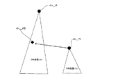
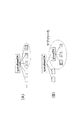
図10は、図3(b),図4に示したデータの関係を、一般化して示す図である。
図3(b),図4に示したデータの関係は、図10に示すように一般化して表されうる。
図10において、AノードA1に関連するTノードT1−1〜T1−3(,T3−1)とAノードA1とはエッジで結ばれ、AノードA2に関連するTノードT2−1〜T2−3(,T3−2)とAノードA2とはエッジで結ばれ、AノードAnとTノードTn−1〜Tn−3,T2−3(,T3−n)とはエッジで結ばれている。
TノードT2−3は、AノードA2,Anの両方とエッジで結ばれており、このことは、TノードT2−3が、AノードA2,Anの両方に関連することを示している。
ここで、AノードA1,A2,Anにより関連付けられる一連の情報が、共通の関連性を有するときには、新たな関連ノードA3が定義されうる。
例えば、AノードA1が、ハムレットの原作に関する情報であり、AノードA2が、ハムレットの翻訳に関する情報であり、AノードAnが、ハムレットの公演に関する情報であるときには、これらのAノードA1,A2,Anにより示される関連情報は、ハムレットに関する情報としての共通性を有する。
FIG. 10 is a diagram showing the relationship between the data shown in FIGS. 3B and 4 in a generalized manner.
The relationship between the data shown in FIGS. 3B and 4 can be generalized as shown in FIG.
In FIG. 10, T nodes T1-1 to T1-3 (, T3-1) related to A node A1 and A node A1 are connected by an edge, and T nodes T2-1 to T2- related to A node A2 are connected. 3 (, T3-2) and A node A2 are connected by an edge, and A node An and T nodes Tn-1 to Tn-3, T2-3 (, T3-n) are connected by an edge.
The T node T2-3 is connected to both the A nodes A2 and An by an edge, which indicates that the T node T2-3 is related to both the A nodes A2 and An.
Here, when a series of information related by the A nodes A1, A2, and An has a common relationship, a new related node A3 can be defined.
For example, when the A node A1 is information related to Hamlet's original, the A node A2 is information related to Hamlet's translation, and the A node An is information related to Hamlet's performance, these A nodes A1, A2, The related information indicated by An has commonality as information regarding Hamlet.
そこで、AノードA1,A2,Anにより関連付けられる情報が、共通性を有することを示すために、新たな関連ノードA3が定義され、データベースに格納される。
また、図10中に破線で囲って示すように、AノードA1およびTノードT1−1〜T1−3により示される一連の情報を具体的に記述するために、新たなTノードT3−1が定義され、データベースに格納される。
さらに、同様に、AノードA2,Anの関連を具体的に記述する新たなTノードT3−2,T3−nが定義され、データベースに格納される。
例えば、TノードT3−1には、見出しの内容として「ハムレット著作について」、TノードT3−2には、見出しの内容として「ハムレット日本語訳について」、TノードT3−nには、見出し内容として「ハムレット公演について」などのデータが定義され、データベースに格納される。
Therefore, a new related node A3 is defined and stored in the database in order to indicate that the information associated by the A nodes A1, A2 and An has commonality.
In addition, as indicated by a broken line in FIG. 10, in order to specifically describe a series of information indicated by the A node A1 and the T nodes T1-1 to T1-3, Defined and stored in the database.
Further, similarly, new T nodes T 3-2 and T 3-n that specifically describe the relationship between the
For example, in the T node T3-1, the headline content is “About Hamlet work”, the T node T3-2 is the headline content “About Hamlet Japanese translation”, and the T node T3-n is the headline content. As such, data such as “About Hamlet Performance” is defined and stored in the database.
さらに、新たなAノードA3と、Tノード3−1〜T3−nそれぞれとの間に、関連性役割Rが定義され、データベースに格納される。
例えば、新たなAノードA3とTノードT3−1との間に、関連性役割Rとして「原作情報」が定義され、新たなAノードA3とTノードT3−2との間に、関連性役割Rとして「翻訳情報」が定義され、新たなAノードA3とTノードT3−nとの間に、関連性役割Rとして「公演情報」などのデータが定義され、データベースに格納される。
同様に、例えば、AノードA1,A2,AnとTノードT3−1,T3−2,T3−nとの間には、「具象化」という予めシステムにより定義された関連性役割Rが定義される。
Further, the relationship role R is defined between the new A node A3 and each of the T nodes 3-1 to T3-n and stored in the database.
For example, “original information” is defined as the relationship role R between the new A node A3 and the T node T3-1, and the relationship role between the new A node A3 and the T node T3-2. “Translation information” is defined as R, and data such as “performance information” is defined as the relationship role R between the new A node A3 and T node T3-n, and stored in the database.
Similarly, for example, a relationship role R defined in advance by the system as “reification” is defined between the A nodes A1, A2, and An and the T nodes T3-1, T3-2, and T3-n. The
図11は、図9に示した構造を採るデータを記憶するために用いられる関連性役割(AR(Association Role))テーブルを示す図である。
図12は、図9に示した構造を採るデータを記憶するために用いられるTノード用識別子(ID(Identifier))テーブルを示す図である。
図13は、図9に示した構造を採るデータを記憶するために用いられるAノード用識別子(ID)テーブルを示す図である。
DB装置12において、図9に示した構造により関連付けられたAノードおよびTノードと、Tノードのデータは、図11に示すARテーブル、および、図12に示すIDテーブルを用いて記憶される。
FIG. 11 is a diagram showing an association role (AR) table used for storing data having the structure shown in FIG.
FIG. 12 is a diagram showing a T-node identifier (ID (Identifier)) table used to store data having the structure shown in FIG.
FIG. 13 is a diagram showing an A-node identifier (ID) table used for storing data having the structure shown in FIG.
In the
図11に示すARテーブルのエントリそれぞれは、ある1つのAノードと、このAノードに関連付けられた1つのTノードと、これら関連付けられたAノードとTノードとの間に定義される関連性役割(R)を示し、あるAノードの識別子(ID)と、このAノードに関連付けられたTノードの識別子と、これら関連付けられたAノードとTノードとの間に定義された関連性役割(R)を含む。
つまり、ARテーブルのエントリそれぞれは、図9に示したいずれかのエッジの一端にあるAノードの識別子と、このエッジの他端にあるTノードの識別子と、このエッジに対して定義される関連性役割とを含む。
Each entry in the AR table shown in FIG. 11 includes one A node, one T node associated with the A node, and an association role defined between the associated A node and T node. (R), an identifier (ID) of a certain A node, an identifier of a T node associated with this A node, and an association role (R) defined between the associated A node and T node. )including.
That is, each entry in the AR table has an identifier of an A node at one end of any edge shown in FIG. 9, an identifier of a T node at the other end of this edge, and an association defined for this edge. Including sex roles.
このようなエントリを、図9に示した全てのエッジ(T1−1〜A1の間のエッジ〜Tn−mn〜An間のエッジ)について作成し、ARテーブルに記憶することにより、図9に示したAノードとTノードとの関連は、図11に示すARテーブルに記憶される。
また、Tノードそれぞれは、内容(Tノードの名称、Tノード自体のデータおよびTノードにより参照されるデータなど)を有し、さらに、Tノードそれぞれには、ARテーブルの各エントリに記憶される識別子(ID)の他に、このTノードの属性(ノードタイプ(NT);見出属性)が定義される(以下、Tノードが、その内容として、その名称(ノード名(N))のみを有する場合を具体例とする。)。
Such entries are created for all the edges shown in FIG. 9 (the edges between T1-1 to A1 to the edges between Tn-mn to An) and stored in the AR table. The relationship between the A node and the T node is stored in the AR table shown in FIG.
Each T node has contents (such as the name of the T node, data of the T node itself, and data referenced by the T node), and each T node is stored in each entry of the AR table. In addition to the identifier (ID), an attribute of this T node (node type (NT); finding attribute) is defined (hereinafter, the T node has only its name (node name (N)) as its contents. A specific example is the case of having it.)
図12に示すTノード用のIDテーブルのエントリそれぞれは、図9に示したいずれかのTノードの識別子(ID)と、このTノードに対して定義された属性(ノードタイプ(NT))と、このTノードの名称(ノード名(N))とを含む。
このようなエントリを、図9に示した全てのTノードT1−1〜Tn−mnについて作成し、Tノード用のIDテーブルに記憶することにより、図9に示した全てのTノードについてのデータが記憶される。
図13に示すAノード用のIDテーブルのエントリそれぞれは、図9に示したいずれかのAノードの識別子(ID)と、このAノードに対して定義された属性(ノードタイプ(NT’))と、このAノードの名称(ノード名(N’))とを含む。
このようなエントリを、図9に示した全てのAノードA1〜Anについて作成し、Aノード用のIDテーブルに記憶することにより、図9に示した全てのAノードについてのデータが記憶される。
Each of the entries in the ID table for the T node shown in FIG. 12 includes an identifier (ID) of one of the T nodes shown in FIG. 9 and an attribute (node type (NT)) defined for the T node. And the name of the T node (node name (N)).
Such entries are created for all the T nodes T1-1 to Tn-mn shown in FIG. 9 and stored in the ID table for the T node, so that the data for all the T nodes shown in FIG. Is memorized.
Each entry in the ID table for the A node shown in FIG. 13 includes an identifier (ID) of one of the A nodes shown in FIG. 9 and an attribute (node type (NT ′)) defined for the A node. And the name of this A node (node name (N ′)).
By creating such entries for all the A nodes A1 to An shown in FIG. 9 and storing them in the ID table for the A node, the data for all the A nodes shown in FIG. 9 is stored. .
なお、図9に示したAノードとTノードとの関連、AノードのデータおよびTノードのデータを記憶するためには、テーブル形式以外に、同様な形式が採られうるが、以下の説明においては、ARテーブルおよびIDテーブルを用いる場合が具体例とされる。
なお、DB装置12の用途、構成あるいは処理内容によっては、図11に示すように、ARテーブルにおいて、各エントリは、Tノードの識別子(ID)の代わりに、Tノードの内容(ノード名(N))を含んでもよい。
また、同様に、ARテーブルにおいて、各エントリは、Tノードの内容を、さらに含んでもよい。
In order to store the relationship between the A node and the T node, the data of the A node, and the data of the T node shown in FIG. A specific example is the case where an AR table and an ID table are used.
Depending on the usage, configuration, or processing content of the
Similarly, in the AR table, each entry may further include the contents of the T node.
[データ検索]
図14は、図6,図7に示したDB装置12におけるデータ検索方法を例示する図である。
ここでは、図14に示すように、あるAノードに、TノードT1〜Tnおよび検索結果(出力)とされるべきTノードTret(T return)が関連付けられ、AノードとTノードT1〜Tn,Tretとの間に、関連性役割R1〜Rn,Rretが定義され、TノードT1〜Tn,Tretが、ノード名N1〜Nn,Nretを有する場合を具体例とする。
[data search]
FIG. 14 is a diagram illustrating a data search method in the
Here, as shown in FIG. 14, a T node T1 to Tn and a T node Tret (T return) to be a search result (output) are associated with a certain A node, and the A node and the T nodes T1 to Tn, A specific example is a case where relationship roles R1 to Rn and Rret are defined between Tret and T nodes T1 to Tn and Tret have node names N1 to Nn and Nret.
DB装置12においては、検索結果として得たいTノードに対して定義される関連性役割Rretと、検索のために用いられ得るAノードの属性(ノードタイプNT;図14においてANT1,ANT2)と、検索のために用いられ得るTノードの関連性役割Rとノード名Nの1つ以上の組み合わせとが検索条件として用いられる。
この検索条件は、図14に示すように、例えば、(Rret,(ANT1,ANT2,...),Filter),Filter=((R1,N1),(R2,N2),...,(Rn,Nn))と表記される。
なお、この検索条件は、後述するように、さらにTノードの属性NT(第3の条件データ)を含みうる。
上記検索条件の内、Filterに含まれるTノードの関連性役割Rとノード名Nの1つ以上の組み合わせ(R1,N1),(R2,N2),...,(Rn,Nn)それぞれは、検索のためのフィルタとして用いられるので、以下、検索フィルタとも記載される。
In the
As shown in FIG. 14, for example, (Rret, (ANT1, ANT2,..., Filter), Filter = ((R1, N1), (R2, N2),. Rn, Nn)).
As will be described later, this search condition can further include an attribute NT (third condition data) of the T node.
Of the above search conditions, one or more combinations (R1, N1), (R2, N2),. . . , (Rn, Nn) are used as filters for search, and are also referred to as search filters hereinafter.
また、上記検索条件の内、Aノードの属性(ANT1,ANT2,...)は、省略されうる。
図15は、図6,図7に示したDB装置12における検索の全体的な処理(S20)を示す第1のフローチャートである。
図15に示すように、ステップ200(S200)において、DB装置12は、例えば、PC102(図6)あるいはDB装置12の入出力装置126に対する検索者の操作に応じて、図14に例示した検索条件を受け入れる。
Of the above search conditions, the attributes of the A node (ANT1, ANT2,...) Can be omitted.
FIG. 15 is a first flowchart showing an overall search process (S20) in the
As illustrated in FIG. 15, in step 200 (S200), the
ステップ22(S22)において、図16を参照して後述する検索フィルタに基づく関連ノードの選択を行う。
ステップ24(S24)において、図17を参照して後述するノードIDおよびノード名の取得を行う。
In step 22 (S22), a related node is selected based on a search filter described later with reference to FIG.
In step 24 (S24), a node ID and a node name described later with reference to FIG. 17 are acquired.
ステップ202(S202)において、DB装置12は、S24の処理により検索結果として得られたTノードTretの識別子(ノードID)およびノード名(Nret)から、検索者に対して返す応答を作成する。
この応答としては、ノード名Nretのみ、ノードTretにより参照される様々なデータ、あるいは、ノードTret自体を示すデータなど、様々なデータを例示されうる。
In step 202 (S202), the
Examples of the response include various data such as only the node name Nret, various data referred to by the node Tret, or data indicating the node Tret itself.
ステップ204(S204)において、DB装置12は、検索者による問い合わせが終了したか否かを判断する。
DB装置12は、検索者による問い合わせが終了した場合には処理を終了し、これ以外のときにはS200の処理に戻る。
In step 204 (S204), the
The
図16は、図15に示した検索フィルタに基づく関連ノードの選択処理(S22)を示すフローチャートである。
図16に示すように、図15に示したS200の処理において、DB装置12は、検索条件(Rret,(ANT1,ANT2,...),Filter),Filter=((R1,N1),(R2,N2),...,(Rn,Nn))を受け入れると、ステップ220(S220)において、処理のために用いられる関連ノードリストを初期化する。
FIG. 16 is a flowchart showing related node selection processing (S22) based on the search filter shown in FIG.
As shown in FIG. 16, in the process of S200 shown in FIG. 15, the
この関連ノードリストには、ARテーブル(図11)から得られたAノードのうち、検索条件中のAノードの属性(ノードタイプ;ANT1,ANT2,...)のいずれかを、その属性(ノードタイプNT)として含むAノードの識別子が記憶される。
なお、検索条件において、Aノードの属性が省略された((ANT1,ANT2,...)=null)ときには、S220の処理において、ARテーブル(図11)から得られたAノードの全ての識別子が記憶される。
ステップ222(S222)において、DB装置12は、全ての検索フィルタ(Ri,Ni)について処理を行ったか否かを判断する。
In the related node list, one of the attributes of the A node (node type; ANT1, ANT2,...) In the search condition among the A nodes obtained from the AR table (FIG. 11) is displayed. The identifier of the A node included as the node type NT) is stored.
If the attribute of the A node is omitted in the search condition ((ANT1, ANT2,...) = Null), all identifiers of the A node obtained from the AR table (FIG. 11) are obtained in the process of S220. Is memorized.
In step 222 (S222), the
DB装置12は、全ての処理について処理を行ったときにはS24(図15,図17)の処理に進み、これ以外のときには、まだ処理の対象とされていないいずれかの検索フィルタ(Ri,Ni)を、次の処理対象としてS224の処理に進む。
ステップ224(S224)において、DB装置12は、Tノード用のIDテーブル(図12)を検索し、検索フィルタ(Ri,Ni)のノード名Niを含むエントリの全てを探し出し、探し出されたエントリに含まれるTノードの識別子の集合(ノードID集合T)を作成する(T={Ti|ノード名=Ni in IDテーブル})。
なお、検索条件にTノードの属性(ノードタイプ;NT)が含まれ、検索フィルタが(Ri,Ni,NTi)と表されるときには、DB装置12は、S224の処理において、IDテーブルから、検索フィルタ(Ri,Ni,NTi)のノード名NiおよびノードタイプNTiを含むエントリを探し出し、探し出されたエントリに含まれるTノードの識別子の集合をノードID集合Tとすればよい。
The
In step 224 (S224), the
When the search condition includes the attribute of the T node (node type; NT) and the search filter is expressed as (Ri, Ni, NTi), the
ステップ226(S226)において、DB装置12は、S224の処理により得られたノードID集合Tが空集合であるか否かを判断する。
DB装置12は、ノードID集合Tが空集合であるときには検索処理を終了するための処理(検索が失敗した旨を検索者に表示するなど)を行い、検索処理を終了し、これ以外のときにはS228の処理に進む。
ステップ228(S228)において、DB装置12は、ARテーブル(図11)を検索し、関連ノードリストAを更新する。
つまり、DB装置12は、ARテーブルから、検索フィルタ(Ri,Ni)の関連性役割Riと、S224の処理により得られたノードID集合Tに含まれるいずれかのTノードの識別子を含むエントリの全てを探し出し、探し出されたエントリに含まれるAノードの識別子を、関連ノードリストAに格納する(A={Aj|役割Ri,Tノードの識別子Ti(all i),Aノード識別子∈A in ARテーブル})。
In step 226 (S226), the
When the node ID set T is an empty set, the
In step 228 (S228), the
In other words, the
ステップ230(S230)において、DB装置12は、S228の処理により得られた関連ノードリストAが空集合であるか否かを判断する。
DB装置12は、関連ノードリストAが空集合であるときには検索処理を終了するための処理を行い、検索処理を終了し、これ以外のときにはS232の処理に進む。
ステップ232(S232)において、DB装置12は、検索条件に含まれる処理されていない検索フィルタを読み込み、S222の処理に戻る。
In step 230 (S230), the
The
In step 232 (S232), the
図17は、図15,図16に示したノードIDおよびノード名取得処理(S24)を示すフローチャートである。
図17に示すように、検索フィルタに基づく関連ノードの選択処理(S22)が終了すると、ステップ240(S240)において、DB装置12は、ARテーブル(図11)を検索し、Tノード識別子集合Tを作成する。
つまり、DB装置12は、ARテーブルから、検索条件に含まれる関連性役割Rretと、S22(S228)の処理により得られた関連ノードリストAに含まれるいずれかのAノードの識別子とを含むエントリの全てを探し出し、探し出されたエントリに含まれるTノードの識別子の集合(Tノード識別子集合T)を作成する(T={Tm|役割=Rret,Aノードの識別子∈A in ARテーブル})。
FIG. 17 is a flowchart showing the node ID and node name acquisition process (S24) shown in FIGS.
As shown in FIG. 17, when the related node selection process (S22) based on the search filter is completed, in step 240 (S240), the
That is, the
ステップ242(S242)において、DB装置12は、S240の処理により得られたTノード識別子集合Tが空集合であるか否かを判断する。
DB装置12は、Tノード識別子集合Tが空集合であるときには終了処理を行って検索処理を終了し、これ以外のときにはS244の処理に進む。
ステップ244(S244)において、DB装置12は、Tノード用のIDテーブル(図12)を検索し、ノードIDとノード名の組の集合Pを作成する。
つまり、DB装置12は、IDテーブルから、S240の処理により作成されたTノード識別子集合Tに含まれるTノードの識別子Tmのいずれかを含むエントリの全てを探し出し、このエントリに含まれるノード名Nmと、Tノードの識別子Tmとの組の集合Pを作成する(P={(Tm,Nm)|Tノードの識別子=Tm(all m) in IDテーブル})。
In step 242 (S242), the
When the T node identifier set T is an empty set, the
In step 244 (S244), the
That is, the
ステップ246(S246)において、DB装置12は、S244の処理により得られたTノード識別子とTノード名との組の集合Pが空集合であるか否かを判断する。
DB装置12は、Tノード識別子とTノード名との組の集合Pが空集合であるときには終了処理を行って検索処理を終了し、これ以外のときにはS202の処理に進む。
この集合Pは、図15に示したS202の処理において、検索者への応答を作成するために用いられる。
In step 246 (S246), the
When the set P of the T node identifier and T node name is an empty set, the
This set P is used to create a response to the searcher in the process of S202 shown in FIG.
[DBプログラム2]
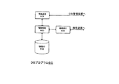
図18は、図6,図7に示したDB装置12において実行されるDBプログラム2の構成を示す図である。
なお、図18においては、図示の明確化のために、データの流れを示す線は、適宜、省略されている。
図18に示すように、DBプログラム2は、DB管理部20、DB部24およびDB検索部26から構成される。
[DB program 2]
FIG. 18 is a diagram showing the configuration of the
In FIG. 18, the lines indicating the data flow are omitted as appropriate for clarity of illustration.
As shown in FIG. 18, the
DB管理部20は、管理操作受入部200、ARエントリ作成部202、IDエントリ作成部204、ARデータベース管理部(ARDB管理部)206およびIDデータベース管理部(IDDB管理部)208から構成される。
DB部24は、ARデータベース(ARDB)240、Tノード用のIDデータベース(IDDB)242およびAノード用のIDDB244から構成される。
DB検索部26は、検索操作受入部260、検索条件作成部262、検索制御部264、ARデータベース検索部(ARDB検索部)266およびIDデータベース検索部(IDDB検索部)268から構成される。
The
The
The
DBプログラム2は、例えば、記録媒体130(図7)を介してDB装置12に供給され、メモリ124にロードされ、DB装置12で実行されるOS上で、DB装置12のハードウエアを具体的に利用して実行される(以下の各プログラムについて同様)。
DBプログラム2は、これらの構成部分により、図9〜図17を参照して説明したARデータベース(図11)およびIDデータベース(図12,図13)の作成、および、これらのデータベースを用いたデータの検索(図14〜図17)を行う。
The
The
DB部24において、ARDB240は、図11に示したARテーブルを記憶する。
IDDB242は、図12に示したTノード用のIDテーブルを記憶する。
IDDB244は、図13に示したAノード用のIDテーブルを記憶する。
また、図18には、図12,図13に示したTノード用のIDテーブルおよびAノード用のIDテーブルが、それぞれIDDB242,244に記憶される場合が具体例とされているが、Tノード用のIDテーブルと、Aノード用のIDテーブルとは、同じデータベースに記憶されてもよい。
また、Tノード用のIDテーブルと、Aノード用のIDテーブルとは、必ずしも分けて作成されなくともよく、1つのデータベース内に一体に作成されてもよい。
In the
The
The
18 shows a specific example in which the ID table for T node and the ID table for A node shown in FIGS. 12 and 13 are stored in
Further, the ID table for the T node and the ID table for the A node are not necessarily created separately, and may be created integrally in one database.
DB管理部20において、管理操作受入部200は、ARテーブルおよびIDテーブルに記憶されたデータを管理し、あるいは、変更するための操作を、入出力装置126(図7)から、あるいは、ネットワーク100を介してPC102(図6)から受け入れ、ARDB管理部206およびIDDB管理部208に対して出力する。
また、管理操作受入部200は、AノードおよびTノード、AノードとTノードとの関連付け、AノードとTノードとの間(エッジ)に定義される関連性役割R、AノードおよびTノードに付される識別子(ID)、Tノードに付されるノード名(N)、および、Tノードに定義される属性(図9)を指定するユーザの操作を受け入れ、ARエントリ作成部202およびIDエントリ作成部204に対して出力する。
例えば、管理操作受入部200は、Aノード、Tノードおよびこれらの間の関係などを、図14に示したように表示するユーザインターフェース(UI)画像を、入出力装置126に表示し、このUI画像に対するユーザの操作を受け入れて、これらの指定を受け入れる。
In the
In addition, the management
For example, the management
ARエントリ作成部202は、管理操作受入部200から入力されるユーザの指定に従って、図11に示したARテーブルのエントリを作成し、ARDB管理部206に対して出力する。
ARDB管理部206は、ARエントリ作成部202から入力されるARテーブルのエントリを、ARDB240に記憶されているARテーブルに追加する。
また、ARDB管理部206は、管理操作受入部200から入力されるユーザの操作に従って、ARDB240に記憶されているARテーブルの内容を変更する。
The AR entry creation unit 202 creates an entry in the AR table shown in FIG. 11 in accordance with the user designation input from the management
The
Further, the
また、ARDB管理部206は、ARDB検索部266の検索に応じて、ARDB240に記憶されたARテーブルのエントリを探しだし、ARDB検索部266に対して出力する。
IDエントリ作成部204は、管理操作受入部200から入力される検索者の指定に従って、図12,図13に示したTノード用およびAノード用のIDテーブルのエントリを作成し、IDDB管理部208に対して出力する。
Further, the
The ID entry creation unit 204 creates ID entries for the T node and A node shown in FIGS. 12 and 13 in accordance with the searcher's designation input from the management
IDDB管理部208は、IDエントリ作成部204から入力されるTノード用のIDテーブルのエントリを、IDDB242に記憶されているTノード用のIDテーブルに追加する。
また、IDDB管理部208は、IDエントリ作成部204から入力されるAノード用のIDテーブルのエントリを、IDDB244に記憶されているAノード用のIDテーブルに追加する。
また、IDDB管理部208は、管理操作受入部200から入力されるユーザの操作に従って、IDDB242,244に記憶されているIDテーブルの内容を変更する。
また、IDDB管理部208は、IDDB検索部268の検索に応じて、IDDB242,244に記憶されたIDテーブルのエントリを探し出し、IDDB検索部268に対して出力する。
The IDDB management unit 208 adds the entry in the T node ID table input from the ID entry creation unit 204 to the T node ID table stored in the
Further, the IDDB management unit 208 adds the entry in the ID table for A node input from the ID entry creation unit 204 to the ID table for A node stored in the
Further, the IDDB management unit 208 changes the contents of the ID table stored in the
Further, the IDDB management unit 208 searches for an entry in the ID table stored in the
DB検索部26において、検索操作受入部260は、図14〜図17に示した検索処理に用いられる検索条件(図14、さらに任意のTノードの属性(ノードタイプ(NT))が含まれることがある)を指定するための検索者の操作を、入出力装置126(図7)から、あるいは、ネットワーク100を介してPC102(図6)から受け入れる。
検索操作受入部260は、受け入れた操作を、検索条件作成部262に対して出力する。
In the
The search
検索条件作成部262は、例えば、検索操作受入部260が、自然言語による質問文の形式で検索条件を受け入れるときには、この質問文を構文解析して単語を取り出す。
次に、検索条件作成部262は、ARDB検索部266、IDDB検索部268、ARDB管理部206およびIDDB管理部208を介してARDB240およびIDDB242,244に記憶されたARテーブルおよびIDテーブルを検索して、検索条件として用いられ得る単語を抽出する。
さらに、検索条件作成部262は、抽出された単語を、質問文の構造に沿って組み合わせ、図14に示した形式の検索条件(Rret,(ANT1,ANT2,...),((R1,N1),(R2,N2),...,(Rn,Nn)))を導出し、検索制御部264に対して出力する。
For example, when the search
Next, the search condition creation unit 262 searches the ARDB and the
Further, the search condition creation unit 262 combines the extracted words along the structure of the question sentence, and searches the search conditions (Rret, (ANT1, ANT2,...), ((R1, N1), (R2, N2),... (Rn, Nn))) are derived and output to the
なお、検索者が、図14に示した形式(Rret,(ANT1,ANT2,...),((R1,N1),(R2,N2),...,(Rn,Nn)))で検索条件を、直接、指定するときには、検索条件作成部262は省略され得る。
また、検索条件作成部262は、検索者による検索条件(Rret,(ANT1,ANT2,...),((R1,N1),(R2,N2),...,(Rn,Nn)))の導出を補助するためのツールであってもよい。
Note that the searcher is in the format shown in FIG. 14 (Rret, (ANT1, ANT2,...), ((R1, N1), (R2, N2),..., (Rn, Nn))). When the search condition is directly specified, the search condition creating unit 262 can be omitted.
In addition, the search condition creating unit 262 is configured to search the search conditions by the searcher (Rret, (ANT1, ANT2,...), ((R1, N1), (R2, N2),..., (Rn, Nn)). ) May be a tool for assisting in derivation.
検索制御部264は、検索条件作成部262(検索操作受入部260)から入力される検索条件(Rret,(ANT1,ANT2,...),((R1,N1),(R2,N2),...,(Rn,Nn)))に従って、ARDB検索部266およびIDDB検索部268を制御し、図15〜図17に示したように、ARDB管理部206およびIDDB管理部208を介したARDB240(ARテーブル;図11)およびIDDB242,244(IDテーブル;図12,図13)の検索を行わせる。
また、検索制御部264は、検索条件に従った検索により検索結果(集合P;図17)が得られたときには、この検索結果に基づいて応答を作成し、入出力装置126(図7)に表示し、あるいは、ネットワーク100(図6)を介してPC102の入出力装置126に表示し、検索者に示す。
The
Further, when the search result (set P; FIG. 17) is obtained by the search according to the search condition, the
ARDB検索部266は、検索制御部264の制御に従って、ARDB管理部206を介してARDB240(ARテーブル;図11)を検索し、検索結果を検索制御部264に返す。
IDDB検索部268は、検索制御部264の制御に従って、IDDB管理部208を介してIDDB242,244(IDテーブル;図12,図13)を検索し、検索結果を検索制御部264に返す。
The ARDB search unit 266 searches the ARDB 240 (AR table; FIG. 11) via the
The
[全体動作]
以下、図6,図7に示したDB装置12(DBプログラム2;図18)の全体的な動作を、具体例を挙げて説明する。
[Overall operation]
Hereinafter, the overall operation of the DB apparatus 12 (
[ARテーブルおよびIDテーブルの作成]
まず、DBプログラム2のDB管理部20によるARテーブルおよびIDテーブルの作成処理を説明する。
図19は、図6,図7に示したDB装置12(DBプログラム2;図18)に対して入力されるデータと、これに含まれるデータの検索に含まれる検索条件とを例示する図である。
例えば、DBプログラム2の管理操作受入部200に対して、図19に示すように関連付けられたデータが入力される。
図19に示すデータには、以下のように関連付けられたAノードとTノードとが含まれ、Tノードにはそれぞれノード名が付されている(ただし、Aノードの属性(ノードタイプ(NT))およびノード名、Tノードの属性(ノードタイプ(NT))は、以下の(1)〜(8)および図19において省略)。
[Create AR table and ID table]
First, an AR table and ID table creation process by the
FIG. 19 is a diagram illustrating data input to the DB device 12 (
For example, associated data as shown in FIG. 19 is input to the management
The data shown in FIG. 19 includes an A node and a T node that are associated as follows, and each T node is given a node name (however, the attribute of the A node (node type (NT) ), Node name, and T node attribute (node type (NT)) are omitted in the following (1) to (8) and FIG.
(1)「AノードA1」と「TノードT11」とが関連付けられ、これらの間に「作者」という関連性役割Rが定義され、「TノードT11」には、「シェークスピア(同名の別人)」というノード名が付されている。
(2)「AノードA9」と「TノードT92,T41」とが関連付けられ、これらの間に「作品」および「作者」という関連性役割Rが定義され、「TノードT92,T42」には、「ベニスの商人」および「シェークスピア」というノード名が付されている。
(3)「AノードA4」と「Tノード41,T42」とが関連付けられ、これらの間に「作者」および「作品」という関連性役割Rが定義され、「TノードT42」には、「ハムレット」というノード名が付されている。
(4)「AノードA13」と「TノードT42」とが関連付けられ、これらの間に「脚本」という関連性役割Rが定義されている。
(5)「AノードA19」と「TノードT42」とが関連付けられ、これらの間に「原作」という関連性役割Rが定義されている。
(6)「AノードA10」と「TノードT42」とが関連付けられ、これらの間に「原作」という関連性役割Rが定義されている。
(7)「AノードA10」と「TノードT103,T101」とが関連付けられ、これらの間に「出版」および「翻訳版」という関連性役割Rが定義され、「TノードT103」には、「○○出版」というノード名が付されている。
(8)「AノードA19」と「TノードT191」とが関連付けられ、これらの間に「翻訳版」という関連性役割Rが定義されている。
(1) “A node A1” and “T node T11” are associated with each other, and an association role R “author” is defined between them, and “T node T11” has “Shakespeare (another person of the same name)” "Is attached to the node name.
(2) “A node A9” and “T node T92, T41” are associated with each other, and an associated role R of “works” and “author” is defined between them, and “T nodes T92, T42” , “Venice merchants” and “Shakespeare” are named.
(3) “A node A4” and “T nodes 41, T42” are associated with each other, and an associated role R of “author” and “works” is defined between them, and “T node T42” includes “ The node name is “Hamlet”.
(4) “A node A13” and “T node T42” are associated with each other, and an association role R “screenplay” is defined between them.
(5) “A node A19” and “T node T42” are associated with each other, and an association role R “original” is defined between them.
(6) “A node A10” and “T node T42” are associated with each other, and an association role R “original” is defined between them.
(7) “A node A10” and “T nodes T103, T101” are associated with each other, and an association role R of “publishing” and “translated version” is defined between them, and “T node T103” includes The node name “XX publication” is attached.
(8) “A node A19” and “T node T191” are associated with each other, and an associated role R “translated version” is defined between them.
管理操作受入部200は、入力されたデータを受け入れ、ARエントリ作成部202およびIDエントリ作成部204に対して出力する。
ARエントリ作成部202は、図19に示したデータから、ARテーブルの各エントリを作成し、ARDB管理部206に対して出力する。
The management
The AR entry creation unit 202 creates each entry in the AR table from the data shown in FIG. 19 and outputs it to the
図20は、ARエントリ作成部202(図18)およびARDB管理部206により作成され、ARDB240に記憶されるARテーブルを例示する図である。
なお、以下の図において、nullは、属性(ノードタイプ)・名称(ノード名)がないことを示す。
ARDB管理部206は、ARエントリ作成部202から入力されたARテーブルのエントリを、ARDB240に記憶されているARテーブルに、順次、追加する。
ARエントリ作成部202およびARDB管理部206による処理の結果、図19に示したデータから、図20に示すようなARテーブルが作成され、ARDB240に記憶される。
FIG. 20 is a diagram illustrating an AR table created by the AR entry creation unit 202 (FIG. 18) and the
In the following diagram, null indicates that there is no attribute (node type) / name (node name).
The
As a result of processing by the AR entry creation unit 202 and the
図21は、IDエントリ作成部204(図18)およびIDDB管理部208により作成され、IDDB242に記憶されるTノード用のIDテーブルを例示する図である。
IDエントリ作成部204は、図19に示したデータから、Tノード用のIDテーブルの各エントリを作成し、IDDB管理部208に対して出力する。
IDDB管理部208は、IDエントリ作成部204から入力されたTノード用のIDテーブルのエントリを、IDDB242に記憶されているIDテーブルに、順次、追加する。
IDエントリ作成部204およびIDDB管理部208による処理の結果、図19に示したデータから、図21に示すようなTノード用のIDテーブルが作成され、IDDB242に記憶される。
FIG. 21 is a diagram illustrating an ID table for a T node created by the ID entry creation unit 204 (FIG. 18) and the IDDB management unit 208 and stored in the
The ID entry creation unit 204 creates each entry in the T node ID table from the data shown in FIG. 19 and outputs the entry to the IDDB management unit 208.
The IDDB management unit 208 sequentially adds the entries in the ID table for the T node input from the ID entry creation unit 204 to the ID table stored in the
As a result of processing by the ID entry creation unit 204 and the IDDB management unit 208, an ID table for a T node as shown in FIG. 21 is created from the data shown in FIG. 19 and stored in the
図22は、IDエントリ作成部204(図18)およびIDDB管理部208により作成されるAノードについてのIDテーブルを例示する図である。
また、IDエントリ作成部204は、図19に示したデータから、Aノード用のIDテーブルの各エントリを作成し、IDDB管理部208に対して出力する。
IDDB管理部208は、IDエントリ作成部204から入力されたIDテーブルのエントリを、IDDB244に記憶されているAノード用のIDテーブルに、順次、追加する。
IDエントリ作成部204およびIDDB管理部208による処理の結果、図19に示したデータから、図22に示すようなAノード用のIDテーブルが作成され、IDDB244に記憶される。
FIG. 22 is a diagram illustrating an ID table for the A node created by the ID entry creation unit 204 (FIG. 18) and the IDDB management unit 208.
Further, the ID entry creation unit 204 creates each entry in the ID table for the A node from the data shown in FIG. 19 and outputs it to the IDDB management unit 208.
The IDDB management unit 208 sequentially adds the ID table entries input from the ID entry creation unit 204 to the ID table for the A node stored in the
As a result of processing by the ID entry creation unit 204 and the IDDB management unit 208, an ID table for the A node as shown in FIG. 22 is created from the data shown in FIG. 19 and stored in the
[データの検索]
例えば、検索者が、DB装置12の入出力装置126(図7)に対して、「作家シェークスピアを作者とする作品のうち、戯曲ハムレットを原作とする翻訳版を出版している出版社名は?」と、検索条件を質問文の形式で入力すると、検索条件作成部262は、この質問文を分析し、図19に示すように、この質問文を、前半部分と後半部分の2つに分割する。
検索条件作成部262は、質問文の前半部分「作家シェークスピアを作者とする作品のうち、」について、「作品」に関するデータを探すということから、検索結果とされるべきTノードTretの関連性役割Rretを「作品」とする。
また、検索条件作成部262は、前半部分の「シェークスピアを作者とする」の部分から、検索フィルタ(R1=「作者」,N1=「シェークスピア」)を作成する。
さらに、検索条件作成部262は、TノードTretの関連性役割(Rret=「作品」)と、検索フィルタ(R1=「作者」,N1=「シェークスピア」)とから、質問文の前半に対応する検索条件(Rret,(ANT1),((R1,N1)))=(作品,(null),((作者,シェークスピア)))を作成する。
[Search data]
For example, the searcher makes a request to the input / output device 126 (FIG. 7) of the
Since the search condition creation unit 262 searches for data related to “works” for the first half of the question sentence “among works whose author is Shakespeare”, the relevance role of the T node Tret to be the search result Let Rret be a “work”.
In addition, the search condition creation unit 262 creates a search filter (R1 = “author”, N1 = “Shakespeare”) from the “half of Shakespeare author” portion in the first half.
Further, the search condition creation unit 262 corresponds to the first half of the question sentence from the relevance role (Rret = “works”) of the T node Tret and the search filter (R1 = “author”, N1 = “Shakespeare”). The search condition (Rret, (ANT1), ((R1, N1))) = (works, (null), ((author, shakespeer))) is created.
また、検索条件作成部262は、後半部分「戯曲ハムレットを原作とする翻訳版を出版している出版社名は?」について、「出版している出版社」に関する情報を検索することから、検索結果とされるべきTノードTretの関連性役割Rretを「出版」とする。
また、検索条件作成部262は、後半部分に含まれる「ハムレット」を「原作」とするという条件から、第1の検索フィルタ(R1=「原作」,N1=「ハムレット」)を作成し、さらに、後半部分に含まれる「翻訳版」から、第2の検索フィルタ(R2=「翻訳版」,N2=「null(指定なし)」)を作成する。
さらに、検索条件作成部262は、関連性役割(Rret=「出版」)と、第1の検索フィルタ(R1=「原作」,N1=「ハムレット」)および第2の検索フィルタ(R2=「翻訳版」,N2=「null」)とから、質問文の後半に対応する検索条件(Rret,(ANT1),((R1,N1),(R2,N2)))=(出版,(null),((原作,ハムレット),(翻訳版,null)))を作成する。
Further, the search condition creation unit 262 searches for information related to “publishing publisher” for the latter half “name of publisher publishing translated version based on drama Hamlet”. The relevancy role Rret of the T node Tret to be the result is “published”.
Further, the search condition creation unit 262 creates a first search filter (R1 = “original”, N1 = “hamlet”) from the condition that “hamlet” included in the latter half is “original”. Then, a second search filter (R2 = “translation version”, N2 = “null (no designation)”) is created from the “translation version” included in the latter half.
Further, the search condition creation unit 262 includes a relevance role (Rret = “Publishing”), a first search filter (R1 = “Original”, N1 = “Hamlet”), and a second search filter (R2 = “Translation”). Version ”, N2 =“ null ”), and the search condition (Rret, (ANT1), ((R1, N1), (R2, N2))) = (publishing, (null), ((Original, Hamlet), (Translated version, null))).
検索制御部264は、検索条件作成部262が作成した検索条件に基づいて、以下に示すように、ARDB検索部266およびIDDB検索部268を介してARDB240(ARテーブル;図20)およびIDDB242(Tノード用IDテーブル;図21)を検索し、検索結果を得る。
まず、質問文の前半部分から得られた検索条件から、
(1)検索制御部264は、IDDB242(図18)に記憶されたTノードのIDテーブルを参照し、ノード名が「シェークスピア」であるTノードの識別子(ID)を全て探し出し、この処理の結果として、T11,T31,T41,T51,T81(図21)を得る。
(2)検索制御部264は、ARDB240に記憶されたARテーブル(図20)を参照し、役割が「作者」であり、Tノード識別子が(1)の処理により得られたTノードの識別子と一致するAノード識別子を全て探し出し、この処理の結果として、A1,A4,A9を得る。
(3)検索制御部264は、ARテーブルを参照し、(2)の処理により得られたAノード識別子のうち、関連性役割Rが「作品」であるAノードに対応するTノードの識別子(ID;一般には複数個)を探し出し、この処理の結果として、T42,T92を得る。
(4)検索制御部264は、IDテーブルを参照し、識別子が(3)の処理により得られたTノード識別子に対応するノード名を、そのTノードの識別子(ID)とともに、検索結果とする。
つまり、検索制御部264は、(1)〜(4)の処理により、質問文の前半部分から得られた検索条件(作品,(null),((作者, シェークスピア)))に基づく検索を行い、検索結果(T42,ハムレット),(T92,ベニスの商人)を得る。
次に、質問文の後半部分から得られた検索条件、および、前半部分に対応する検索結果から、
(5)検索制御部264は、質問文の前半部分に対応する検索結果(T42,ハムレット),(T92,ベニスの商人)の内、ノード名が、第1の検索フィルタ(原作,ハムレット)と対応する(T42,ハムレット)を選択し、そのノード識別子(ID)T42を得る
(6)検索制御部264は、ARテーブルを参照し、役割が「原作」であり、Tノード識別子が、(5)の処理により得られたノード識別子(ID)と一致するAノードの識別子を全て探し出し、この結果としてA10,A19を得る。
(7)検索制御部264は、ARテーブルを参照し、(6)の処理により得られたAノード識別子のうち、役割が「翻訳版」であるものを全て探し出し、この結果として、A10,A19を得る。
(8)検索制御部264は、ARテーブルを参照し、(7)の処理により得られたAノード識別子のうち、役割が「出版」であるAノードに対応するTノード識別子を探し出し、この結果としてT103を得る(複数の出版社から翻訳版が出されている場合には、複数のTノード識別子が得られる)。
(9)検索制御部264は、IDテーブルを参照し、ノードIDが(8)で得られたTノード識別子に対応するノード名を、そのノード識別子とともに、検索結果(T103,○○出版)とする。
Based on the search conditions created by the search condition creation unit 262, the
First, from the search conditions obtained from the first half of the question text,
(1) The
(2) The
(3) The
(4) The
In other words, the
Next, from the search conditions obtained from the second half of the question sentence and the search results corresponding to the first half,
(5) The
(7) The
(8) The
(9) The
つまり、検索制御部264は、(5)〜(9)の処理により、質問文の後半部分から得られた検索条件(出版,(null),((原作,ハムレット),(翻訳版,null)))に基づく検索を行い、検索結果(T013,○○出版)を得る。
(10)検索制御部264は、検索結果を、入出力装置126(図7)などに表示し、検索者に示す。
That is, the
(10) The
図23は、第2のDBシステム3の構成を例示する図である。
図23に示すように、第2のDBシステム3は、DB装置12と、DB装置12と同様なハードウエア(図7)上で、DBプログラム2のDB管理部20およびDB部24を実行するDB装置30と、DB装置12と同様なハードウエア上で、DBプログラム2のDB検索部26を実行する検索装置32とが、ネットワーク100を介して接続されて構成される。
このように、DBプログラム2は、必ずしも1つのコンピュータ上で実行されなくともよく、ネットワークを介して接続された複数のコンピュータに分散され、実行されてもよい。
FIG. 23 is a diagram illustrating a configuration of the
As shown in FIG. 23, the
Thus, the
[第3のDBシステム4]
以下、ディレクトリ構造により関連情報を記憶し、検索の対象とするように構成された本発明にかかる第3のDBシステム4を説明する。
図24は、本発明にかかる第3のDBシステム4の構成を例示する図である。
図24に示すように、DBシステム4は、PC102、検索装置40、DB管理装置5およびn台のDB装置6−1〜6−nが、ネットワーク100を介して接続されて構成される。
[Third DB system 4]
Hereinafter, a
FIG. 24 is a diagram illustrating the configuration of the
As shown in FIG. 24, the
なお、以下、DB装置6−1〜6−nなど、複数ある構成部分のいずれかを特定せずに記載するときには、単にDB装置6と記載することがある。
また、検索装置40、DB管理装置5およびDB装置6のハードウエアは、図7に示したような構成を採る。
また、図6に示した第1のDBシステム1におけるDB装置12(図6)およびそのDBプログラム2(図18)のように、DB装置6が検索機能を含むときには、検索装置40は不要とされることがある。
また、DBシステム4においては、DB装置6それぞれに対する複製装置(ミラーサーバ;DB装置6’)が設けられることがある。
また、以下、DB装置6−1〜6−nを、それぞれDB装置A〜Nと記すことがある。
In the following description, when describing without specifying any of a plurality of components such as the DB devices 6-1 to 6-n, the
Moreover, the hardware of the
Further, when the
In the
Hereinafter, the DB devices 6-1 to 6-n may be referred to as DB devices A to N, respectively.
次に、図24に示したDBシステム4における情報の表現を説明する。
図25は、図24に示したDBシステム4に記憶される情報のグラフ形式の表現を例示する図である。
図26は、図25に示した情報のディレクトリ情報ツリー形式の表現を例示する図である。
図8を参照して既に説明したように、AノードおよびTノードそれぞれに対してノード名(Aノードのノード名などが「関連ノードに対応する情報」であり、Tノードのノード名などが「見出ノードに対応する情報」である)などが定義され、AノードとTノードとの間に関連性役割が定義されると、これらのノードにより関連付けられる関連情報は、グラフ形式で、図25に例示するように表現されうる。
Next, the expression of information in the
FIG. 25 is a diagram illustrating a graph representation of information stored in the
FIG. 26 is a diagram exemplifying a directory information tree format representation of the information shown in FIG.
As already described with reference to FIG. 8, the node name for each of the A node and the T node (the node name of the A node is “information corresponding to the related node”, and the node name of the T node is “ If the relationship role is defined between the A node and the T node, the related information related by these nodes is expressed in the form of a graph in FIG. Can be expressed as shown in FIG.
なお、図25には、TノードおよびAノードのノードタイプ(クラス)を定義するノード(T1,T3−1,T3−2)それぞれに、ノード名として「ロケーション情報」・「店」・「エリア」が定義され、Tノード(T2−1,T2−2)それぞれに、ノード名として「店1」・「エリア3」が定義され、Aノード(A1)に、ノード名として「ロケーション」が定義され、TノードとAノートとの間それぞれに、関連性役割として、「建物」・「地域」が定義された場合が示されている。
また、AノードA2−1,A2−2は、ノードタイプ(クラス)を定義するノードと、そのインスタンス(実体に対応するノード)であるノードとの関連を示すので、これらのノードA2−1,A2−2は、利用者が目的に応じて独自に定義した役割ではなく、システムにより事前に定義された「クラス」、「インスタンス」という2つの役割によりTノードを関連付けるという意味で、特別なノードである。
FIG. 25 shows “location information”, “store”, “area” as node names for the nodes (T1, T3-1, T3-2) that define the node types (classes) of the T node and the A node. ”,“
Further, since the A nodes A2-1 and A2-2 indicate the relationship between the node that defines the node type (class) and the node that is the instance (the node corresponding to the entity), these nodes A2-1 and A2-1 A2-2 is a special node in the sense that T-nodes are associated with two roles of “class” and “instance” defined in advance by the system, not the roles that the user uniquely defines according to the purpose. It is.
図25に示したようにグラフ形式で表現された関連情報は、図26に示すように、LDAP(Lightweight Directory Access Protocol)の情報モデルであるDIT(Directory Information Tree;ディレクトリ情報ツリー)形式によって表現されうる。
つまり、図25に示した関連情報は、DIT形式に従って、図26に点線で示すように、DB装置6それぞれの最上位のエントリとして仮想的に設けられる仮想ルートエントリ、および、第1,第2・・・の関係(関係#1,#2・・・)を示すエントリの下に設けられ、図26に実線で示すように、Aノードに対応するエントリ、および関連性役割に対応し、Tノードの情報を属性としてもつエントリにより表現されうる。
つまり、図26に例示した場合においは、ノードタイプ(assocType)が「ロケーション情報」である関連情報を示すエントリ「ロケーション」の直下に、2つの役割(role)「建物」と「地域」に対応するエントリが設けられ、それぞれの役割を果たすメンバ(member)「店1」と「エリア3」は対応するエントリの属性となっている。
図25に示したようにグラフ形式で表現された関連情報は、図26に示すように、LDAP(Lightweight Directory Access Protocol)の情報モデルであるDIT(Directory Information Tree;ディレクトリ情報ツリー)形式によって表現されうる。
The related information expressed in the graph format as shown in FIG. 25 is expressed in the DIT (Directory Information Tree) format which is an information model of LDAP (Lightweight Directory Access Protocol) as shown in FIG. sell.
That is, the related information shown in FIG. 25 includes, according to the DIT format, the virtual route entry that is virtually provided as the top entry of each
That is, in the case illustrated in FIG. 26, two roles “building” and “region” correspond to the entry “location” indicating the related information whose node type (assocType) is “location information”. The entries “
The related information expressed in the graph format as shown in FIG. 25 is expressed in the DIT (Directory Information Tree) format which is an information model of LDAP (Lightweight Directory Access Protocol) as shown in FIG. sell.
なお、図26に示したDIT形式において、『ディレクトリ』は、実世界の様々な事物に関する情報を、できる限り実世界での関係に即したわかりやすい形で構成し、また、情報の在り処を持っていて、それらの情報の検索や更新の手段を提供するものとして定義される。
また、『エントリ』は、実世界のオブジェクトに関する情報を、オブジェクトクラスに従って整理・分類し、ディレクトリ情報として表現したものとして定義され、あるいは、ディレクトリに格納したデータと定義される。
また、『ディレクトリ情報ツリー』は、エントリ(ディレクトリ情報)を、階層的に管理する際、その階層関係をツリー構造に表現したものとして定義される。
つまり、図26の各四角はエントリに対応し、これらの階層関係をツリー構造に表現したものがディレクトリ情報ツリー(DIT)である。
In the DIT format shown in FIG. 26, the “directory” is composed of information related to various things in the real world in an easy-to-understand form as much as possible in accordance with the relationship in the real world, and has the location of the information. Therefore, it is defined as providing a means for searching and updating such information.
An “entry” is defined as information regarding real-world objects organized and classified according to an object class and expressed as directory information, or defined as data stored in a directory.
In addition, the “directory information tree” is defined as a hierarchical structure of entries (directory information) expressed in a tree structure when managing the entries (directory information) hierarchically.
That is, each square in FIG. 26 corresponds to an entry, and the directory information tree (DIT) represents these hierarchical relationships in a tree structure.
なお、上述したように、エントリはオブジェクトに関する情報の集まりであって、このオブジェクトに関する情報は『属性』と呼ばれる。
この属性は『属性型』と、1つ以上の値、『属性値(群)』からなり、図26においては、各エントリの構造が、『属性型:属性値』の形式で、下表21〜表23に示すように、LDAPにおける各エントリの構造表現として例示されている。
例えば、「ou=関係#1」直下のエントリでは、属性型objectclass(オブジェクトクラス)の属性値が 関連ノード、属性型cn(一般名)の属性値がロケーション、・・・というように、エントリの各属性が定義される。
As described above, an entry is a collection of information about an object, and the information about the object is called “attribute”.
This attribute is composed of “attribute type” and one or more values, “attribute value (group)”. In FIG. 26, the structure of each entry is in the form of “attribute type: attribute value” in the following table 21. As shown in Table 23, it is exemplified as a structural representation of each entry in LDAP.
For example, in the entry immediately below “ou =
図27は、ディレクトリ構造で表現された関連情報の分割方法を例示する図である。
図28は、図27に示したDB装置6−1(A)のエントリdn_A2と、DB装置6−n(N)のエントリdn_Nとの参照関係を示す図である。
図27に示すように、DIT形式により表現された関連情報は、ディレクトリ構造に従って分割されうる。
FIG. 27 is a diagram illustrating a method for dividing related information expressed in a directory structure.
FIG. 28 is a diagram illustrating a reference relationship between the entry dn_A2 of the DB device 6-1 (A) and the entry dn_N of the DB device 6-n (N) illustrated in FIG.
As shown in FIG. 27, the related information expressed in the DIT format can be divided according to the directory structure.
図27に示す場合においては、関連情報は、エントリdn_Aおよびその下位のエントリdn_A1,dn_A2を含むディレクトリ構造により表現されており、さらに、エントリdn_A1以下のディレクトリに対応する関連情報は、エントリdn_B〜dn_(N−1)に対応して分割され、エントリdn_A2以下のディレクトリに対応する関連情報は、エントリdn_N以下のディレクトリ構造に対応付けられている(なお、図27に示した例においては、エントリdn_B〜dn_Nを最上位エントリとするディレクトリ構造がサブツリーであり、これらのサブツリー全てを含み、エントリdn_Aを最上位エントリとするディレクトリ構造がディレクトリツリーである)。
例えば、図28に示すように、図27に示したDB装置6−n(N)の最上位エントリdn_Nは、DB装置6−1(A)のエントリdn_A2の下位にあって、これを参照する。
このように、ディレクトリ構造に従って分割された関連情報は、図27に示すように、DB装置6−1〜6−nに、分割されて記憶されうる。
In the case shown in FIG. 27, the related information is expressed by a directory structure including the entry dn_A and its lower entries dn_A1 and dn_A2, and the related information corresponding to the directories below the entry dn_A1 is the entries dn_B to dn_A. The related information that is divided corresponding to (N-1) and corresponds to the directory below the entry dn_A2 is associated with the directory structure below the entry dn_N (in the example shown in FIG. 27, the entry dn_B The directory structure having ~ dn_N as the top entry is a subtree, and the directory structure including all these subtrees and having the entry dn_A as the top entry is a directory tree).
For example, as shown in FIG. 28, the uppermost entry dn_N of the DB device 6-n (N) shown in FIG. 27 is lower than the entry dn_A2 of the DB device 6-1 (A), and this is referred to. .
In this way, the related information divided according to the directory structure can be divided and stored in the DB devices 6-1 to 6-n as shown in FIG.
図29は、図27に示したようにDB装置6−1〜6−n(DB装置A〜N)に分割されて記憶された関連情報を管理するために用いられるディレクトリツリーテーブルを例示する図である。
図27,図28に示したように分割されてDB装置6−1〜6−n(A〜N)に記憶された関連情報を管理するためには、図29に示すようなディレクトリツリーテーブルが用いられる。
図29に示すように、ディレクトリツリーテーブルには、DB装置6−1〜6−nそれぞれの装置名(A〜N)と、これらのDB装置6それぞれにおける最上位エントリ(dn_A〜dn_N;仮想ルートエントリ(図26)に同じ)と、DB装置6それぞれの最上位エントリが参照するエントリ(上位参照エントリ)と、各DB装置6に複製装置(ミラーサーバ(第2のデータベース装置))があるときのその装置名(A',C'など)とが、対応付けられて含まれる。
FIG. 29 is a diagram illustrating a directory tree table used for managing related information divided and stored in the DB devices 6-1 to 6-n (DB devices A to N) as shown in FIG. It is.
In order to manage the related information divided and stored in the DB devices 6-1 to 6-n (A to N) as shown in FIGS. 27 and 28, a directory tree table as shown in FIG. Used.
As shown in FIG. 29, in the directory tree table, the device names (A to N) of the DB devices 6-1 to 6-n and the highest-level entries (dn_A to dn_N; virtual roots) of these
図30は、図27,図28に示したDB装置6−1〜6−n(A〜N)に記憶されているディレクトリツリー(またはサブツリー)それぞれの最上位エントリdn_A〜dn_Nと、ディレクトリツリー(またはサブツリー)それぞれに記憶されている関連情報の分類に用いられる分類型・分類値(分類情報)とを対応付ける情報テーブルを例示する図である。
図25,図26に示したように、DIT形式のディレクトリ構造で表現され、このディレクトリ構造に従って分割され、DB装置6−1〜6−n(A〜N)それぞれに記憶された関連情報それぞれは、DB装置6−1〜6−n(A〜N)それぞれにおいて関連性を有する情報の集合としてとらえられる。
FIG. 30 shows the top-level entries dn_A to dn_N of the directory trees (or subtrees) stored in the DB devices 6-1 to 6-n (A to N) shown in FIGS. (Or subtree) is a diagram illustrating an information table associating classification types and classification values (classification information) used for classification of related information stored in each.
As shown in FIGS. 25 and 26, each of the related information expressed in the directory structure of the DIT format and divided according to the directory structure and stored in each of the DB devices 6-1 to 6-n (A to N) The DB devices 6-1 to 6-n (A to N) are regarded as a set of information having relevance.
従って、図27,図28に示したDB装置6−1〜6−n(A〜N)に記憶されているディレクトリツリー(またはサブツリー)それぞれに対して、そこに記憶されている関連情報の分類に用いるための属性などを示す分類型および分類値を定義することができる。
DB装置6−1〜6−n(A〜N)それぞれに記憶された関連情報の管理のためには、図30に示すように、図27,図28に示したDB装置6−1〜6−n(A〜N)の最上位エントリdn_A〜dn_Nの下のサブツリーa〜nそれぞれと、最上位エントリ(dn_A〜dn_N)それぞれと、これらの最上位エントリ以下のサブツリーに対して定義される分類型および分類値それぞれとが対応付けて含まれる情報テーブルが用いられる。
Therefore, for each directory tree (or sub-tree) stored in the DB devices 6-1 to 6-n (A to N) shown in FIGS. 27 and 28, the classification of the related information stored therein. A classification type and a classification value indicating an attribute to be used in the process can be defined.
In order to manage the related information stored in each of the DB devices 6-1 to 6-n (A to N), as shown in FIG. 30, the DB devices 6-1 to 6-6 shown in FIGS. -N (A to N) sub-trees a to n below the highest-level entries dn_A to dn_N, the highest-level entries (dn_A to dn_N), and the classifications defined for the sub-trees below these highest-level entries An information table including a type and a classification value in association with each other is used.
なお、図30に示した「分類型」は、関連タイプ(Aノードのノードタイプ(図22);属性)に対応する。
また、「分類値」は、LDAP情報モデルにおけるインスタンスに対応する。
図27〜図30に示した最上位エントリとなり得るエントリとして、
(1)ある分類型(関連タイプ;Aノードのノードタイプ)の特定の分類値(インスタンス)を含むサブツリーのルートエントリ、および、
(2)ある特定の分類値(インスタンス)が含まれる関連情報を含むサブツリーのルートエントリ
などを、具体例として挙げることができる。
Note that the “classification type” illustrated in FIG. 30 corresponds to a relation type (node type of node A (FIG. 22); attribute).
The “classification value” corresponds to an instance in the LDAP information model.
As an entry that can be the top entry shown in FIGS.
(1) a root entry of a subtree including a specific classification value (instance) of a certain classification type (association type; node type of A node), and
(2) A specific example is a root entry of a subtree including related information including a specific classification value (instance).
ただし、ここには、「分類型」が関連タイプに対応し、「分類値」がそのインスタンスに対応する場合が例示されているが、これは、図30を図27,図28に対応付けた一例であって、「分類型」は、関連タイプに対応しないことがあり、また、「分類値」は、そのインスタンスに対応しないことがある。
例えば、図30に示されたサブツリーaには、「分類型:カテゴリ、分類値:提携会社情報」の関連情報が含まれ、これらは、「分類型」が関連タイプに対応せず、「分類値」がそのインスタンスに対応しない例である。
However, here, a case where “classification type” corresponds to a related type and “classification value” corresponds to an instance thereof is illustrated. This corresponds to FIG. 30 corresponding to FIG. 27 and FIG. As an example, a “classification type” may not correspond to an association type, and a “classification value” may not correspond to its instance.
For example, the subtree a shown in FIG. 30 includes related information of “classification type: category, classification value: partner company information”, and the “classification type” does not correspond to the related type. In this example, “value” does not correspond to the instance.
また、例えば、図30に示した情報テーブル中の最上位エントリdn_Bを含むエントリの分類型として示された「位置情報」は、上記(1)「ある分類型(関連タイプ;Aノードのノードタイプ)の特定の分類値(インスタンス)を含むサブツリーのルートエントリ」の分類型の一例であり、その分類値の1つとして分類値「ロケーション(located-in)」を含む。
このエントリは、分類値として「ロケーション(located-in)」を有する全ての関連情報が、DB装置6−2(B)に記憶されることを示している。
分類型「位置情報」の分類値のその他の例として、分類値「隣接(next-to)」などを挙げることができる。
Further, for example, the “location information” shown as the classification type of the entry including the highest entry dn_B in the information table shown in FIG. 30 is the above (1) “certain classification type (related type; node type of A node). ) Of a sub-tree root entry including a specific classification value (instance) ”, and one of the classification values includes a classification value“ located-in ”.
This entry indicates that all related information having “located-in” as the classification value is stored in the DB device 6-2 (B).
As another example of the classification value of the classification type “position information”, a classification value “next-to” can be cited.
あるいは、図30に示した最上位エントリdn_(N−1)を含むエントリの分類型として示された「建物」は、上記(2)「ある特定の分類値(インスタンス)が含まれる関連情報を含むサブツリーのルートエントリ」の分類型の一例であり、その分類値の1つとして分類値「店1」を含む。
このエントリは、分類値として「店1(Store_1)」を有する全ての関連情報が、DB装置6−(n−1)(N−1)に記憶されることを示している。
Alternatively, the “building” shown as the classification type of the entry including the highest-level entry dn_ (N−1) shown in FIG. 30 is related information (2) “related information including a specific classification value (instance)”. It is an example of a classification type of “root entry of a sub-tree to be included”, and one of the classification values includes a classification value “
This entry indicates that all related information having “Store 1 (Store_1)” as the classification value is stored in the DB device 6- (n−1) (N−1).
[関連情報の作成および検索]
以下、図25〜図30を参照して説明したDIT形式のディレクトリ構造により表現された関連情報の作成、および、作成された関連情報に対する検索を説明する。
[Create and search related information]
Hereinafter, creation of related information expressed by the directory structure in the DIT format described with reference to FIGS. 25 to 30 and search for the created related information will be described.
[第1のDB管理プログラム50]
図31は、図24に示したDB管理装置5において動作する第1のDB管理プログラム50の構成を示す図である。
図31に示すように、DB管理プログラム50は、ユーザインターフェース(UI)部500、情報登録部502、情報送信部504、関連情報作成・管理部510(ディレクトリツリー作成手段および情報対応付手段)、ツリー情報提供部512、ディレクトリツリーテーブル作成部522(最上位エントリ対応付手段)、ディレクトリツリーテーブル管理部524、ディレクトリツリーテーブルDB526、情報テーブル作成部532(分類情報対応付手段)、情報テーブル管理部534および情報テーブルDB536から構成される。
[First DB management program 50]
FIG. 31 is a diagram showing a configuration of the first
As shown in FIG. 31, the
DB管理プログラム50は、これらの構成部分により、図25〜図26に示したように、DIT形式のディレクトリ構造で表現された関連情報を作成する。
また、DB管理プログラム50は、図27,図28に示したように、作成した関連情報を分割してDB装置6−1〜6−nに記憶させ、図29,図30に示したディレクトリツリーテーブルおよび情報テーブルを用いて関連情報を管理する。
また、DB管理プログラム50は、検索装置40(図24)に対して、ディレクトリツリーテーブルおよび情報テーブルの情報に含まれ、検索のために必要とされる情報(ツリー情報)を、適宜、提供する。
The
Also, as shown in FIGS. 27 and 28, the
Further, the
図32は、図31に示したDB管理プログラム50が、DB管理装置5の入出力装置126(図7)に表示するGUI画像を例示する図である。
DB管理プログラム50において、UI部500は、DB管理装置5あるいはPC102のユーザのためにGUI環境を提供し、入出力装置126(図7)などに対して、図32に示すようなGUI画像を表示する。
さらに、UI部500は、表示されたGUI画像に対してユーザが行った関連情報の登録、管理および変更のための操作を受け入れ、情報登録部502および関連情報作成・管理部510など、DB管理プログラム50の各構成部分に対して出力し、これらの動作を制御する。
また、UI部500は、DB管理プログラム50の各構成部分が作成した情報を、入出力装置126に対して表示・出力する。
なお、UI部500は、DB管理装置5におかれても、PC102におかれてもよく、PC102において、上記機能をユーザに対して提供してもよい。
32 is a diagram illustrating a GUI image displayed on the input / output device 126 (FIG. 7) of the
In the
Furthermore, the
Further, the
The
関連情報作成・管理部510は、ディレクトリツリーテーブル作成部522および情報テーブル作成部532などの動作を制御して、UI部500から入力されるTノード、Aノードおよび関連属性を示す情報から、図26に示したように、DIT形式のディレクトリ構成により表現される関連情報を作成し、作成した関連情報を、図29,図30に示したディレクトリツリーテーブルおよび情報テーブルを用いて管理する。
また、関連情報作成・管理部510は、要求に応じて、ディレクトリツリーテーブルおよび情報テーブルに含まれ、検索装置40による検索のために用いられる情報(ツリー情報)を、ツリー情報提供部512に対して出力する。
また、関連情報作成・管理部510は、ユーザの操作などに従って、図27,図28に示したように、DIT形式のディレクトリ構造に表現された関連情報を分割し、情報登録部502に対して出力する。
The related information creation / management unit 510 controls the operations of the directory tree table creation unit 522, the information
Also, the related information creation / management unit 510 sends information (tree information) included in the directory tree table and the information table and used for searching by the searching
In addition, the related information creation / management unit 510 divides the related information expressed in the directory structure in the DIT format as shown in FIGS. Output.
情報登録部502は、関連情報作成・管理部510から入力される関連情報を、情報送信部504を介して、DB装置6−1〜6−nそれぞれに対して送信し、登録を要求する。
ツリー情報提供部512は、検索装置40からの要求に応じて、関連情報作成・管理部510から入力されるツリー情報を提供する。
The
The tree
ディレクトリツリーテーブル作成部522は、関連情報作成・管理部510の制御に従って、図29に示したディレクトリツリーテーブルを作成し、ディレクトリツリーテーブル管理部524に対して出力する。
ディレクトリツリーテーブル管理部524は、ディレクトリツリーテーブル作成部522から入力されたディレクトリツリーテーブルを、ディレクトリツリーテーブルDB526に記憶させる。
また、ディレクトリツリーテーブルDB526は、要求に応じて、ディレクトリツリーテーブルDB526に記憶させたディレクトリツリーテーブルを、関連情報作成・管理部510に対して出力する。
なお、図18に示したDBプログラム2においては、DB管理部20が、関連情報からARテーブルおよびIDテーブルを作成する処理を行うのに対し、図31に示したDB管理プログラム50においては、関連情報作成・管理部510が、ディレクトリ構造の関連情報(図21,図22)を作成し、DB装置6が、関連情報作成・管理部510および情報送信部504を介して、作成されたディレクトリ構造の関連情報を受け取り、記憶・管理する。
The directory tree table creation unit 522 creates the directory tree table shown in FIG. 29 under the control of the related information creation / management unit 510 and outputs the directory tree table to the directory tree
The directory tree
Further, the directory
In the
情報テーブル作成部532は、関連情報作成・管理部510の制御に従って、図30に示した情報テーブルを作成し、情報テーブル管理部534に対して出力する。
情報テーブル管理部534は、情報テーブル作成部532から入力された情報テーブルを、情報テーブルDB536に記憶させる。
また、情報テーブル管理部534は、要求に応じて、情報テーブルDB536に記憶させた情報テーブルを、関連情報作成・管理部510に対して出力する。
The information
The information
Further, the information
以下、DB管理プログラム50の全体的な処理を説明する。
図33は、図31に示したDB管理プログラム50による関連情報の登録処理(S30)を示すフローチャートである。
図33に示すように、ステップ300(S300)において、DB管理プログラム5またはPC102のUI部500は、入出力装置126に、図32に例示したGUI画像を表示する。
ユーザは、表示されたGUI画像に対して操作を行い、新たに追加する関連情報に関する情報(データ)を各フィールドに入力する。
Hereinafter, the overall processing of the
FIG. 33 is a flowchart showing related information registration processing (S30) by the
As shown in FIG. 33, in step 300 (S300), the
The user operates the displayed GUI image, and inputs information (data) related to newly added related information in each field.
ステップ302(S302)において、関連情報作成・管理部510は、S300の処理において入力した関連情報に基づき、関連性(テーマ;例えば「シェークスピア作品」など)を同定する。
ステップ304(S304)において、関連情報作成・管理部510は、関連情報のノードタイプ(分類型;例えば「著作情報」)を同定し、これをエントリの属性として設定する。
ステップ306(S306)において、関連情報作成・管理部510は、情報テーブル管理部534を介して、情報テーブルを参照し、設定されたテーマおよびノードタイプにより、作成されるエントリが、いずれのサブツリーに分類されるかを特定する。
In step 302 (S302), the related information creation / management unit 510 identifies relevance (theme; for example, “Shakespeare work”) based on the related information input in the processing of S300.
In step 304 (S304), the related information creation / management unit 510 identifies the node type (classification type; for example, “copy information”) of the related information, and sets this as the attribute of the entry.
In step 306 (S306), the related information creation / management unit 510 refers to the information table via the information
ステップ310(S310)において、関連情報作成・管理部510は、ディレクトリツリーテーブル管理部524を介して、ディレクトリツリーテーブルを参照し、S306の処理により求められたサブツリーが、いずれのDB装置6に記憶されているかを特定する。
ステップ312(S312)において、関連情報作成・管理部510は、UI部500を介して入力された関連情報に関するデータに基づき、それに対応するエントリを作成する。
In step 310 (S310), the related information creation / management unit 510 refers to the directory tree table via the directory tree
In step 312 (S 312), the related information creation / management unit 510 creates an entry corresponding to the data related to the related information input via the
ステップ314(S314)において、関連情報作成・管理部510は、情報登録部502および情報送信部504を介して、S310の処理により特定されたDB装置6に、追加された関連情報のエントリを送信する。DB装置6は、受信した関連情報のエントリが既に記憶されているか否かを判断する。
なお、関連情報作成・管理部510は、DB装置6に記憶する際の前処理として、DB装置6内の情報を利用する。
この情報には、各エントリdn(distinguished name:識別名)が割り当てられており、この識別名により、DIT内の全てのエントリが一意に識別され得るので、同一のエントリの存在の有無が判断されうる。
DB管理プログラム50は、追加された関連情報のエントリが既に存在するとの結果をDB装置6から受信したときには処理を終了し、これ以外のときにはS316の処理に進む。
ステップ316(S316)において、関連情報作成・管理部510は、追加された関連情報のエントリを、特定されたDB装置6に対して登録する。
In step 314 (S314), the related information creation / management unit 510 transmits the entry of the added related information to the
Note that the related information creation / management unit 510 uses information in the
Each entry dn (distinguished name) is assigned to this information, and since all the entries in the DIT can be uniquely identified by this identification name, it is determined whether or not the same entry exists. sell.
The
In step 316 (S316), the related information creation / management unit 510 registers the entry of the added related information in the specified
図34は、図31に示したDB管理プログラム50による情報テーブル(図30)の変更処理(S34)を示すフローチャートである。
ステップ340(S340)において、ユーザは、DB管理装置5(図24)またはPC102に対して、変更しようとするサブツリーを指定する操作を行い、さらに、指定したサブツリーの分類型・分類値を設定する操作を行う。
関連情報作成・管理部510は、UI部500を介してこれらの操作を受け入れる。
ステップ342(S342)において、ユーザは、DB管理装置5(図24)またはPC102に対して、指定したサブツリーの最上位エントリを設定する操作を行う。
関連情報作成・管理部510は、UI部500を介して、この操作を受け入れる。
FIG. 34 is a flowchart showing the information table (FIG. 30) change process (S34) by the
In step 340 (S340), the user performs an operation for specifying the subtree to be changed on the DB management apparatus 5 (FIG. 24) or the
The related information creation / management unit 510 accepts these operations via the
In step 342 (S342), the user performs an operation for setting the top entry of the designated subtree on the DB management apparatus 5 (FIG. 24) or the PC.
The related information creation / management unit 510 accepts this operation via the
ステップ344(S344)において、関連情報作成・管理部510は、S340,S342の処理により受け入れた操作が示す分類型、分類値および最上位エントリの全てが、指定されたサブツリーに対して設定されているか否かを判断する。
関連情報作成・管理部510は、情報テーブル管理部534を介して情報テーブルを読み出し、これらの全てが指定されたサブツリーに対して設定されているときには処理を終了し、これ以外のときにはS346の処理に進む。
In step 344 (S344), the related information creation / management unit 510 sets all of the classification type, classification value, and top-level entry indicated by the operation accepted by the processing of S340 and S342 for the specified subtree. Determine whether or not.
The related information creation / management unit 510 reads the information table via the information
ステップ346(S346)において、関連情報作成・管理部510は、受け入れた設定値(指定されたサブツリー、分類型、分類値および最上位エントリ)を、情報テーブル管理部534に対して出力する。
情報テーブル管理部534は、関連情報作成・管理部510から入力された設定値を、情報テーブルに設定し、情報テーブルDB536に記憶する。
In step 346 (S346), the related information creation / management unit 510 outputs the accepted setting values (specified subtree, classification type, classification value, and top entry) to the information
The information
図35は、図31に示したDB管理プログラム50によるディレクトリツリーテーブルの変更処理(S36)を示すフローチャートである。
図35に示すように、ステップ360(S360)において、UI部500は、DB管理装置5から、ユーザによるディレクトリ情報ツリー分割のための操作を受ける。
ステップ362(S362)において、関連情報作成・管理部510は、ディレクトリツリーテーブル管理部524からディレクトリツリーテーブル(図29)を得て、DB装置6の配置およびそのディレクトリ構造を示す情報を取得し、ユーザに対して表示する。
FIG. 35 is a flowchart showing directory tree table change processing (S36) by the
As shown in FIG. 35, in step 360 (S360), the
In step 362 (S362), the related information creation / management unit 510 obtains a directory tree table (FIG. 29) from the directory tree
ステップ364(S364)において、UI部500は、表示したディレクトリ構造に対するユーザの操作に応じて、分割後のサブツリーの最上位エントリおよびその上位参照エントリの設定を受ける。
ステップ366(S366)において、関連情報作成・管理部510は、ユーザによるディレクトリ情報ツリー分割のための操作に基づき、分割されたサブツリーが記憶されるDB装置6に、複製装置を設定するか否かを判断する。
DB管理プログラム50は、複製装置を設定するときにはS368の処理に進み、これ以外のときにはS370の処理に進む。
In step 364 (S364), the
In step 366 (S366), the related information creation / management unit 510 determines whether or not to set a replication device in the
The
ステップ368(S368)において、関連情報作成・管理部510は、S366の処理において複製装置を設定すると判断されたとき、その複製装置を特定する。
ステップ370(S370)において、関連情報作成・管理部510は、分割後のサブツリーの最上位エントリとその上位参照エントリおよび複製装置を設定するときにはその複製装置名を、ディレクトリツリーテーブル管理部524に対して出力する。
ディレクトリツリーテーブル管理部524は、関連情報作成・管理部510から入力されたこれらの情報を、ディレクトリツリーテーブルDB526の所定の部分に書き込みに反映させる。
In step 368 (S368), the related information creation / management unit 510 identifies the duplication device when it is determined in step S366 that the duplication device is set.
In step 370 (S370), the related information creation / management unit 510 sets the duplication device name to the directory tree
The directory tree
ステップ372(S372)において、関連情報作成・管理部510は、全てのDB装置6についてのディレクトリツリーテーブルの変更処理が終了したか否かを判断する。
DB管理プログラム50は、全てのDB装置6についての変更処理が終了していないときにはS364の処理に戻る。
In step 372 (S372), the related information creation / management unit 510 determines whether or not the directory tree table change processing for all the
The
次に、DB管理装置5の全体的な処理を説明する。
図36は、図31に示したDB管理プログラム50の全体的な動作(S40)を示すシーケンス図である。
図36に示すように、ステップ400(S400)ユーザは、DB管理プログラム50のUI部500に対して、関連情報を入力する。
ステップ402(S402)において、UI部500は、入力された関連情報に関する情報(データ)を、関連情報作成・管理部510に対して出力する。
関連情報作成・管理部510は、これらの情報を受け入れる。
Next, overall processing of the
FIG. 36 is a sequence diagram showing an overall operation (S40) of the
As shown in FIG. 36, the user in Step 400 (S400) inputs related information to the
In step 402 (S402), the
The related information creation / management unit 510 accepts such information.
ステップ404(S404)において、関連情報作成・管理部510は、受け入れた関連情報に関する情報のうち、テーマおよびノードタイプなど関連情報の分類に用いられる分類情報(分類型・分類値)を、情報テーブル管理部534に対して出力する。
ステップ406(S406)において、情報テーブル管理部534は、関連情報作成・管理部510からの関連情報の分類に用いられる情報を受け入れ、これらに対応するサブツリーの最上位エントリを、関連情報作成・管理部510に返す。
関連情報作成・管理部510は、このサブツリー最上位エントリを受け入れる。
なお、これらに対応するサブツリーがない場合には、対応するサブツリー最上位エントリの代わりに、DB装置6−1の最上位エントリ(すなわち、ルートエントリ)を関連情報作成・管理部510に返す。
In step 404 (S404), the related information creation / management unit 510 stores, in the information table, the classification information (classification type / classification value) used for classification of the related information such as the theme and node type among the information related to the received related information. The data is output to the
In step 406 (S406), the information
The related information creation / management unit 510 accepts the top entry of the subtree.
If there is no corresponding subtree, the highest entry (that is, the root entry) of the DB device 6-1 is returned to the related information creation / management unit 510 instead of the highest entry of the corresponding subtree.
S406の処理においては、情報テーブル(図30)に格納されている分類型・分類値に対応する情報が用いられ、図32に示したGUI画像を介して入力される関連情報に関するデータは、全て、関連情報作成・管理部510で利用可能である。
つまり、関連情報作成・管理部510が、ノードタイプと特定のインスタンスとを組にして情報テーブル管理部534に対して与えることにより、情報テーブル管理部534は、関連情報の分類に用いられる情報に対応するサブツリーの最上位エントリを得ることができ、他には、例えば、「カテゴリ」が分類型として、「シェークスピア作品」が分類値として、情報テーブル管理部534に与えられ得る。
In the process of S406, information corresponding to the classification type and classification value stored in the information table (FIG. 30) is used, and all the data related to the related information input via the GUI image shown in FIG. It can be used by the related information creation / management unit 510.
In other words, the related information creation / management unit 510 provides the information
ステップ408(S408)において、関連情報作成・管理部510は、ディレクトリツリーテーブル管理部524に対して、S406の処理により得られたサブツリー最上位エントリを出力する。
ディレクトリツリーテーブル管理部524は、このサブツリー最上位エントリを受け入れる。
ステップ410(S410)において、ディレクトリツリーテーブル管理部524は、受け入れたサブツリー最上位エントリを用いてディレクトリツリーテーブルDB526を検索し、このサブツリーを記憶するDB装置6を特定する。特定されたDB装置6を示す情報を、関連情報作成・管理部510に返す。
In step 408 (S408), the related information creation / management unit 510 outputs the top entry of the subtree obtained by the process of S406 to the directory tree
The directory tree
In step 410 (S410), the directory tree
ステップ412(S412)において、関連情報作成・管理部510は、DIT形式とした関連情報と、特定されたDB装置6を示す情報とを情報登録部502に対して出力する。
情報登録部502は、入力された関連情報を、特定されたDB装置6に対して転送し、登録する。
ステップ416〜422(S416〜S422)において、情報登録部502からUI部500に対して、登録の結果(正常終了または異常終了)が通知され、ユーザに対して表示される。
In step 412 (S412), the related information creation / management unit 510 outputs related information in the DIT format and information indicating the identified
The
In steps 416 to 422 (S416 to S422), the
[第2のDBプログラム60]
図37は、図24に示したDB装置6それぞれにおいて動作する第2のDBプログラム60を示す図である。
図37に示すように、DBプログラム60は、情報管理部600、情報DB602、情報通信部604および検索実行部606から構成される。
DBプログラム60は、これらの構成部分により、DB管理装置5(DB管理プログラム50;図31)から、DIT形式のディレクトリ構造で表現され、適宜、分割された関連情報の登録を受け、記憶する。
また、DBプログラム60は、検索装置40からの検索に応じて、登録された関連情報を提供する。
また、DBプログラム60は、DB管理装置5からの制御に従って、登録された関連情報の変更を行う。
[Second DB program 60]
FIG. 37 is a diagram showing a
As shown in FIG. 37, the
With these components, the
Further, the
Further, the
DBプログラム60において、情報通信部604は、DB管理装置5による関連情報およびその登録要求、および、関連情報の変更要求を受け入れ、情報管理部600に対して出力する。
検索実行部606は、検索装置40からの検索条件(図38に示して後述する検索プログラム42の検索条件作成部420により作成されるLDAP操作、および、図50に示すLDAP操作)に従って、情報管理部600に対して、関連情報の検索を行う。
また、検索実行部606は、検索の結果として情報管理部600から入力される関連情報を、検索を要求した検索装置40に対して返す。
In the
The
In addition, the
情報管理部600は、DB管理装置5からの登録要求および変更要求に従って、DB管理装置5または他のDB装置6から送られてきた関連情報(図26〜図28)を、情報DB602に記憶させる。
また、情報管理部600は、検索装置40による検索に応じて、情報DB602から関連情報を読み出して、検索実行部606に対して出力する。
The
Further, the
[第1の検索プログラム42]
図38は、図24に示した検索装置40において動作する検索プログラム42を示す図である。
図38に示すように、検索プログラム42は、図18に示したDB検索部26に、検索条件作成部420および検索結果出力部422を付加した構成をとる。
検索プログラム42は、これらの構成部分により、検索者(ユーザ)の検索操作に従って、DB装置6に対する検索処理を行い、検索の結果として得られた関連情報を検索者に示す。
[First search program 42]
FIG. 38 is a diagram showing a search program 42 that operates in the
As shown in FIG. 38, the search program 42 has a configuration in which a search
The search program 42 performs a search process on the
検索プログラム42において、検索操作受入部260は、検索装置40の入出力装置126(図7)などに対して、検索者が入力した検索操作を受け入れ、検索条件作成部420に対して出力する。
検索条件作成部420(ディレクトリツリー検索手段)は、検索操作受入部260から入力された検索操作の内容を解析し、さらに、この検索操作の内容に適合したツリー情報(ディレクトリツリーテーブルおよび情報テーブル(図29,図30)の内、検索に必要とされる情報)を、DB管理装置5から得て、検索操作およびツリー情報に適合した検索条件を作成し、検索制御部264に対して出力する。
In the search program 42, the search
The search condition creation unit 420 (directory tree search means) analyzes the content of the search operation input from the search
具体的には、検索条件作成部420は、検索操作の内容を解析して得られる、関連情報の分類型および分類値に従って、DB管理装置5からの情報テーブル(図30)を受けてその内容を検索し、検索操作の内容に適合した関連情報の最上位エントリを求める(但し、このような最上位エントリがない場合には、検索条件作成部420は、DB装置6−1の最上位エントリdn_Aを、検索操作の内容に適合した関連情報の最上位エントリとする)。
さらに、検索条件作成部420は、DB管理装置5から受けたディレクトリツリーテーブル(図29)の内容を検索し、情報テーブルの検索により求められた最上位エントリを記憶するDB装置6を特定する。
さらに、検索条件作成部420は、検索操作の内容、および、情報テーブルから得られる関連情報の分類に用いる属性(分類型・分類値)を用いて、DB装置6に実行させるべきLDAP操作のコマンドおよびパラメータを作成し、検索条件として、検索制御部264に対して出力する。
Specifically, the search
Further, the search
Further, the search
検索制御部264(情報検索手段)は、検索条件作成部420から入力される検索条件をDB装置6に対して出力し、関連情報の検索の制御を行う。
検索結果出力部422は、検索の結果としてDB装置6から返された関連情報を、検索装置40の入出力装置126(図7)などに対して表示・出力し、検索者に示す。
The search control unit 264 (information search means) outputs the search condition input from the search
The search
以下、検索プログラム42の全体的な処理を説明する。
図39は、図38に示した検索プログラム42による検索処理(S44)を示すフローチャートである。
図39に示すように、ステップ440(S440)において、検索操作受入部260は、ユーザによる検索条件を受け入れる。
Hereinafter, the overall processing of the search program 42 will be described.
FIG. 39 is a flowchart showing the search process (S44) by the search program 42 shown in FIG.
As shown in FIG. 39, in step 440 (S440), the search
ステップ442(S442)において、検索操作受入部260は、検索要求メッセージ(図50を参照して後述)を作成し、検索条件作成部420に対して出力する。
ステップ444(S444)において、検索条件作成部420は、検索要求メッセージ中に、分類型および分類値の指定があるか否かを判断する。
検索条件作成部420は、分類型および分類値の指定があるときにはS446の処理に進み、これ以外のときにはS454の処理に進む。
In step 442 (S442), the search
In step 444 (S444), the search
The search
ステップ446(S446)において、検索条件作成部420は、DB管理装置5に対して分類型および分類値を送り、これらに対応するサブツリーの最上位エントリを特定する。
ステップ448(S448)において、検索条件作成部420は、S446の処理により、サブツリーが特定されたか否かを判断する。
検索プログラム42は、サブツリーが特定されたときにはS450の処理に進み、これ以外のときにはS454の処理に進む。
In step 446 (S446), the search
In step 448 (S448), the search
The search program 42 proceeds to the process of S450 when the subtree is specified, and proceeds to the process of S454 otherwise.
ステップ450(S450)において、検索条件作成部420は、DB管理装置5に対して特定された最上位エントリを送り、この最上位エントリに対応するサブツリーを記憶するDB装置6を特定する。
ステップ452(S452)において、検索条件作成部420は、特定されたサブツリーの最上位エントリを、検索を開始するエントリ(検索ベース)とする。
ステップ454(S454)において、検索条件作成部420は、DB管理装置5からディレクトリツリーテーブルを受け、受けたディレクトリツリーテーブルを参照し、全てのDB装置6に記憶されているサブツリーを通して、最も上位のエントリ(ルートエントリ)を検索ベースとし、このエントリを記憶するDB装置6を特定する。
In step 450 (S450), the search
In step 452 (S452), the search
In step 454 (S454), the search
ステップ456(S456)において、検索制御部264は、検索条件作成部420から、検索要求および検索ベースなどの情報を得て、特定されたDB装置6に対するLDAP操作コマンドを作成する。
ステップ458(S458)において、検索制御部264は、作成したLDAP操作コマンドを用いて、DB装置6に対する検索を実行し、その結果を受けて出力する。
In step 456 (S456), the
In step 458 (S458), the
以下、さらに、検索プログラム42の処理を、DB管理プログラム50の処理と関連付けて、全体的に説明する。
図40は、図31に示したDB管理プログラム50および図38に示した検索プログラム42の全体的な処理(S52)を示すシーケンス図である。
図40に示すように、ステップ520(S520)において、検索プログラム42の検索操作受入部260は、ユーザの問い合わせ操作を受け入れる。
ステップ522(S522)において、検索操作受入部260は、検索条件作成部420に対して、検索要求メッセージを送信する。
Hereinafter, the processing of the search program 42 will be described as a whole in association with the processing of the
FIG. 40 is a sequence diagram showing an overall process (S52) of the
As shown in FIG. 40, in step 520 (S520), the search
In step 522 (S522), the search
ステップ526(S526)において、検索条件作成部420は、DB管理プログラム50の関連情報作成・管理部510に対して、検索要求メッセージに含まれる分類型および分類値を送信する。
なお、S526の処理は、S446において、検索条件作成部420からDB管理装置5に対して分類型・分類値を送信する処理に対応する。
ステップ528(S528)において、関連情報作成・管理部510は、検索条件作成部420から受けた分類型・分類値を情報テーブル管理部534に対して出力する。
In step 526 (S526), the search
The process of S526 corresponds to the process of transmitting the classification type / classification value from the search
In step 528 (S528), the related information creation / management unit 510 outputs the classification type / classification value received from the search
ステップ530(S530)において、情報テーブル管理部534は、関連情報作成・管理部510から入力された分類型・分類値を用いて情報テーブルを参照し、入力された分類型・分類値に対応する最上位エントリを得る。
情報テーブル管理部534は、得られた最上位エントリを、関連情報作成・管理部510に返す。
In step 530 (S530), the information
The information
ステップ532(S532)において、関連情報作成・管理部510は、S530の処理により得られた最上位エントリをディレクトリツリーテーブル管理部524に対して出力する。
ステップ534,536(S534,S536)において、ディレクトリツリーテーブル管理部524は、入力された最上位エントリに対応するDB装置6を、関連情報作成・管理部510を介して検索条件作成部420に返す。
In step 532 (S532), the related information creation / management unit 510 outputs the highest-level entry obtained by the processing of S530 to the directory tree
In
ステップ538(S538)において、検索条件作成部420は、検索条件を作成し、特定されたDB装置6の名前などとともに、検索制御部264に対して出力する。
ステップ540(S540)において、検索制御部264は、LDAPコマンドを作成し、特定されたDB装置6にアクセスして検索を行う。
ステップ542〜546(S542〜S546)において、DB装置6から検索結果が返され、ユーザに対して表示される。
In step 538 (S538), the search
In step 540 (S540), the
In
[DBシステム4における関連情報およびその検索の例(1)]
以下、DBシステム4においてどのように関連情報が登録され、登録された関連情報が検索されるかについて、具体例を挙げて説明する。
図41は、図24に示したDBシステム4においてDB装置6に登録されるディレクトリ構造の関連情報を例示する第1の図であって、フラットなディレクトリ構造を示す。
図41に示されたディレクトリ構造においては、図26に点線で示されたエントリ(ou=関係#1〜#n)がなく、ルートエントリの直下に全ての関連情報がある。
このようなディレクトリ構造を、「フラットな構造のディレクトリ構造」と呼ぶ。
[Example of related information and search in DB system 4 (1)]
Hereinafter, how the related information is registered in the
FIG. 41 is a first diagram illustrating the related information of the directory structure registered in the
In the directory structure shown in FIG. 41, there is no entry (ou =
Such a directory structure is called a “flat structure of the directory”.
ユーザが、DB管理装置5(図24)あるいはPC102の入出力装置126(図7)に表示されたGUI画像(図32)に対して、順次、関連情報を登録するための操作を行う。
この操作により、(関連名称,関連型,名称,役割)の形式で、DB管理装置5に対して、以下に示すような、
(ハムレット・著作について、著作情報、シェークスピア、作者),
(ハムレット・著作について、著作情報、ハムレット、作品),
(ベニスの商人・著作について、著作情報、シェークスピア、作者),
(ベニスの商人・著作について、著作情報、ベニスの商人、作品),
(ハムレット・日本語訳について、翻訳情報、ハムレット、原作),
(ハムレット・日本語訳について、翻訳情報、ハムレット日本語訳、翻訳版),
(ハムレット・日本語訳について、翻訳情報、出版、OO出版),・・・
などの情報が入力される。
The user sequentially performs operations for registering related information on the GUI image (FIG. 32) displayed on the DB management device 5 (FIG. 24) or the input / output device 126 (FIG. 7) of the
By this operation, in the form of (related name, related type, name, role), the
(About Hamlet and work, copyright information, Shakespeare, author),
(About Hamlet and work, copyright information, Hamlet, works),
(About Venice merchants and works, copyright information, Shakespeare, author),
(Venice merchants and works, copyright information, merchants and works of Venice),
(Hamlet, Japanese translation, translation information, hamlet, original),
(For Hamlet / Japanese translation, translation information, Hamlet Japanese translation, translated version),
(For Hamlet / Japanese translation, translation information, publication, OO publication), ...
Such information is input.
ユーザによる登録操作の結果として、図41に示すようなDIT形式のディレクトリ構造により関連情報が作成される。
なお、図41に例示するフラットな構造のディレクトリ構造においては、ディレクトリ情報ツリーをサブツリーに分割することは考慮されておらず、分類型および分類値は、ディレクトリ情報ツリー全体に対して定義されるが、必要に応じて、フラットな構造のディレクトリ構造を、サブツリーに分割することも可能である。
このディレクトリ構造においては、仮想ルートエントリの下に、5つのAノード(「ハムレット・著作について」,「ベニスの商人・著作について」,「ハムレット・日本語訳について」,「ハムレット・中国語訳について」,「ハムレット・上演について」;A4,A9,A10,A19,A13(図19などを参照))に対応するエントリが設けられる。仮想ルートエントリに対しては、分類型および分類値が定義され、定義された分類型および分類値は、DB管理装置5において、図30に示した情報テーブルにより管理される。
As a result of the registration operation by the user, related information is created with a directory structure in the DIT format as shown in FIG.
In the flat directory structure illustrated in FIG. 41, it is not considered to divide the directory information tree into subtrees, and the classification type and the classification value are defined for the entire directory information tree. If necessary, the flat directory structure can be divided into sub-trees.
In this directory structure, under the virtual root entry, there are five A nodes ("About Hamlet / Work", "About Vendor's Merchant / Work", "About Hamlet / Japanese Translation", "About Hamlet / Chinese Translation"). ”,“ About Hamlet / Performance ”; A4, A9, A10, A19, A13 (see FIG. 19 and the like)) are provided. For the virtual route entry, a classification type and a classification value are defined, and the defined classification type and classification value are managed by the
また、このディレクトリ構造においては、これらAノードに対応するエントリそれぞれに、Aノードそれぞれがもつ関連性役割に対応する下位エントリが設けられ、それぞれの役割を果たすTノード(T41,T42,T92,T101,T103,T191;図19を参照)に関する情報をエントリの属性とする。
図41に示した関連情報は、全て1つのDB装置6−1(図24)に記憶され、あるいは、最上位エントリごとに分割されて、5つのDB装置6−1〜6−5に記憶され、検索プログラム42による検索の対象とされる。
Further, in this directory structure, each entry corresponding to these A nodes is provided with a lower level entry corresponding to the relevance role possessed by each A node, and T nodes (T41, T42, T92, T101) playing the respective roles. , T103, T191; refer to FIG. 19) are the attributes of the entry.
All the related information shown in FIG. 41 is stored in one DB device 6-1 (FIG. 24), or divided for each top-level entry and stored in five DB devices 6-1 to 6-5. The search program 42 makes a search target.
図42,図43は、図41に示したディレクトリ構造の関連情報を例示する第2,第3の図である。
なお、図42には、シェークスピアによる作品という一つの関連性(テーマ)に着目し、それに対応する「シェークスピア作品」エントリをルートエントリ下に新たに設け、その配下に関連情報を置くことにより、テーマに基づく階層化を実現する場合が例示されており、「シェークスピア作品」というエントリは、図26に点線で示されたエントリ(ou=関係#1〜#n)に対応する。
42 and 43 are second and third diagrams illustrating the related information of the directory structure shown in FIG.
In FIG. 42, focusing on one relevance (theme) called a work by Shakespeare, a new “Shakespeare work” entry corresponding to it is newly created under the root entry, and related information is placed under the theme, In the example shown in FIG. 26, the entry “shakespeare work” corresponds to the entry (ou =
さらに、図43には、「著作」・「翻訳」・「上演」という異なる分類型(関連タイプ;Aノードのノードタイプ)を表現するエントリが定義され、「シェークスピア作品」エントリ下に新たに設けられる場合が例示されている。
このように、関連情報を、それぞれの関連タイプ(ノードタイプ)に応じたエントリの配下に登録することにより、関連タイプ(ノードタイプ)に基づく階層化が行われる。
Further, in FIG. 43, entries representing different classification types (related type: node type of A node) such as “work”, “translation”, and “performance” are defined and newly provided under the “Shakespeare works” entry. The case where it is done is illustrated.
In this way, by registering the related information under the entry corresponding to each related type (node type), hierarchization based on the related type (node type) is performed.
図42に示すように、図41に示した関連情報は、さらに階層化されうる。
つまり、図41に示した関連情報に含まれる各ノードに対しては、共通のテーマとして、「シェークスピア作品」が定義されうるので、ユーザは、DB管理装置5を操作して、図42に示すように、5つのAノードに対応するエントリの上に、これらエントリ以下それぞれに記憶される情報が、シェークスピア作品であることを示すエントリを新たに作成し、関連情報のテーマに基づいて、関連情報を階層化してもよい。
As shown in FIG. 42, the related information shown in FIG. 41 can be further hierarchized.
That is, for each node included in the related information shown in FIG. 41, “Shakespeare work” can be defined as a common theme, so the user operates the
図42に示す場合においては、関連情報は、エントリ「シェークスピア作品」の下位にエントリ「ハムレット著作について(A4)」〜「ハムレット上演について(A13)」を含むディレクトリ構造により表現されている。
例えば、エントリ「シェークスピア作品」およびエントリ「ハムレット著作について(A4)」〜「ハムレット中国語訳について(A19)」以下のエントリを、サブツリーとしてDB装置6−1に記憶させ、「ハムレット・上演について(A13)」以下のエントリを、サブツリーとしてDB装置6−2に記憶させるなど、ディレクトリ構造に従って関連情報をサブツリーに分割することができ、分割の結果として得られたサブツリーは、DB装置6−1〜6−nに、分割されて記憶されうる。
In the case shown in FIG. 42, the related information is represented by a directory structure including entries “About Hamlet Works (A4)” to “About Hamlet Performance (A13)” below the entry “Shakespeare Works”.
For example, the entries “Shakespeare work” and entries “About Hamlet work (A4)” to “About Hamlet Chinese translation (A19)” are stored in the DB device 6-1 as a subtree, and “About Hamlet Performance” ( A13) "The following entries can be stored in the DB device 6-2 as subtrees, and the related information can be divided into subtrees according to the directory structure. The subtrees obtained as a result of the division are the DB devices 6-1 to 6-1. 6-n can be divided and stored.
このようなときには、これら「シェークスピア作品」および「ハムレット・上演について」のディレクトリが、最上位エントリとされ、これらの最上位エントリに対しては、分類型および分類値が定義され、定義された分類型および分類値は、DB管理装置5において、図30に示した情報テーブルにより管理され、その参照関係は、図29に示したディレクトリツリーテーブルにより管理される。
In such a case, the directories of “Shakespeare works” and “About Hamlet / Performance” are the top entries, and for these top entries, the classification type and classification value are defined, and the defined classification The type and classification value are managed in the
別の例では、図42に示したように階層化された関連情報のディレクトリ構造の内、「シェークスピア作品」およびその下の「ハムレット・著作について」および「ベニスの商人・著作について」に対応する関連情報が、DB装置6−1に記憶され、「ハムレット・日本語訳について」および「ハムレット・中国語訳について」に対応する関連情報が、DB装置6−2に記憶され、「ハムレット・上演について」に対応する関連情報が、DB装置6−3に記憶される。
なお、最上位エントリは、サブツリー内でのルート(最も上位にある)エントリなので、各DB装置6に記憶されているサブツリーごとに、ただ1つの最上位エントリが定義される。また、分類型・分類値は、この最上位エントリに対して定義される。
In another example, in the directory structure of the related information hierarchized as shown in FIG. 42, it corresponds to “Shakespeare work” and “about Hamlet / work” and “about merchant / work of Venice” below it. The related information is stored in the DB device 6-1, and the related information corresponding to “hamlet / Japanese translation” and “hamlet / Chinese translation” is stored in the DB device 6-2. The related information corresponding to “about” is stored in the DB device 6-3.
Since the highest entry is the root (highest) entry in the subtree, only one highest entry is defined for each subtree stored in each
従って、図42に示した例においては、「ハムレット・日本語訳について」および「ハムレット・中国語訳について」に対応する関連情報を、DB装置6−2に記憶するためには、これら2つのエントリをまとめる上位エントリ(例えば、図43に示す「翻訳情報」に対応するエントリ)が設けられ、これを最上位エントリするサブツリーが記憶されることになる。
このように分割されたサブツリーの参照関係は、図29に示したディレクトリテーブルを用いることにより管理され、サブツリーそれぞれに付された分類型および分類値は、図30に示した情報テーブルを用いることにより管理される。
Therefore, in the example shown in FIG. 42, in order to store related information corresponding to “about Hamlet / Japanese translation” and “about Hamlet / Chinese translation” in the DB device 6-2, A high order entry (for example, an entry corresponding to “translation information” shown in FIG. 43) is provided, and a subtree that stores the top entry is stored.
The reference relationship of the subtree divided in this way is managed by using the directory table shown in FIG. 29, and the classification type and the classification value assigned to each subtree are obtained by using the information table shown in FIG. Managed.
また、さらに、図41に示した5つのAノードの内、A4ノード(「ハムレット・著作について」)とA9ノード(「ベニスの商人・著作について」)とに、「著作情報」が、関連タイプ(ノードタイプ)として定義され、A10ノード(「ハムレット・日本語訳について」)とA19ノード(「ベニスの商人・中国語訳について」)とに、「翻訳情報」が、関連タイプ(ノードタイプ)として定義され、A13ノード(「ハムレット・上映について」)に、「上演情報」が関連タイプ(ノードタイプ)として定義されるようなときには、図43に示すように、定義された関連タイプ(ノードタイプ)ごとの階層化が可能である。 Furthermore, among the five A nodes shown in FIG. 41, “Copy Information” is associated with the A4 node (“About Hamlet / Work”) and the A9 node (“About Vendor / Work of Venice”). (Node type), A10 node ("About Hamlet / Japanese translation") and A19 node ("About Vendor merchant / Chinese translation"), "Translation information" is related type (Node type) When the “performance information” is defined as the relation type (node type) in the A13 node (“About Hamlet / Screening”), as shown in FIG. 43, the defined relation type (node type) ) Can be hierarchized.
例えば、図43に示したように階層化された関連情報のディレクトリ構造の内、「シェークスピア作品」およびその下の「著作情報」に対応する関連情報が、DB装置6−1に記憶され、「翻訳情報」に対応する関連情報が、DB装置6−2に記憶され、「上演情報」に対応する関連情報が、DB装置6−3に記憶される。
このようなときには、「シェークスピア作品」、「翻訳情報」および「上演情報」のエントリが、最上位エントリとされ、これらの最上位エントリに対しては、分類型および分類値が定義され、定義された分類型および分類値は、DB管理装置5において、図30に示した情報テーブルにより管理され、その参照関係は、図29に示したディレクトリツリーテーブルにより管理される。
For example, as shown in FIG. 43, related information corresponding to “Shakespeare work” and “Copyright information” below is stored in the DB device 6-1 in the directory structure of related information hierarchized as shown in FIG. Related information corresponding to “translation information” is stored in the DB device 6-2, and related information corresponding to “performance information” is stored in the DB device 6-3.
In such a case, the entries of “Shakespeare work”, “translation information”, and “performance information” are the top entries, and the classification type and the classification value are defined and defined for these top entries. The classification type and the classification value are managed in the
検索者(ユーザ)が、検索プログラム42(図24)に対して、図41〜図43に示したようにDB装置6に記憶された関連情報に対する検索のための操作を行うと、検索プログラム42は、検索操作の内容を解析し、さらに、この検索操作の内容に適合したツリー情報(ディレクトリツリーテーブル)および情報テーブル(図29,図30)の内、検索に必要とされる情報)を、DB管理装置5から得る。
さらに、検索プログラム42は、検索操作およびツリー情報に適合した検索条件(LDAP操作のコマンドおよびパラメータ)を作成し、検索条件に適合するディレクトリ情報を記憶しているDB装置6に対する検索を行い、検索結果を得る。
このようにして得られた検索結果は、検索プログラム42のユーザに対して表示される。
When the searcher (user) performs an operation for searching the related information stored in the
Further, the search program 42 creates search conditions (LDAP operation commands and parameters) that match the search operation and tree information, searches the
The search results obtained in this way are displayed to the user of the search program 42.
[DBシステム4における関連情報およびその検索の例(2)]
以下、DBシステム4においてどのように関連情報が登録され、登録された関連情報が検索されるかについて、商品、販売店および商品販売促進のためのプログラムを示す販売情報を、さらに具体例として挙げて説明する。
図44,図45は、図24に示したDBシステム4においてDB装置6に登録されるディレクトリ構造の関連情報を例示する第4,第5の図であって、図44は、関東地域のみの販売情報を示し、図45は、関東地域および関西地域を含む販売情報を示す。
[Example of related information and search in DB system 4 (2)]
Hereinafter, sales information indicating a product, a store, and a program for product sales promotion will be further exemplified as an example of how the related information is registered in the
44 and 45 are fourth and fifth diagrams illustrating the related information of the directory structure registered in the
図24に示したDB管理装置5あるいはPC102に対するユーザの操作により、関東地域の販売情報が、図44に示すディレクトリ構造で表現される関連情報として登録される。
つまり、ユーザにより入力された関連情報の登録データに基づき、仮想ルートエントリの直下に、「販売情報」に関するディレクトリ情報をまとめるエントリが設けられ、このエントリの下位に、「関東地域」の販売情報に関するエントリが設けられる。
また、「関東地域」の販売情報に関して、「位置情報」、「提供情報」および「参加情報」を関連タイプ(ノードタイプ)とするエントリが設けられ、これらのエントリの下に、「店舗」、「地区」、「提供先」および「主催」などの関連役割に対応するエントリが設けられ、さらに、これらのエントリそれぞれの属性(この属性は、DB装置6それぞれに記憶されており、この属性を管理するために、独自の管理テーブルは定義、作成されない)として、「店A」・「新宿」など役割を果たすメンバに関する情報(Tノード用IDテーブル(図21)のノードID,ノード名に対応)が登録される。
Sales information in the Kanto region is registered as related information represented by the directory structure shown in FIG. 44 by a user operation on the
That is, based on the registration data of the related information input by the user, an entry for collecting directory information related to “sales information” is provided immediately below the virtual route entry, and below this entry is related to the sales information of “Kanto region”. An entry is provided.
In addition, regarding sales information of “Kanto region”, an entry having “location information”, “provided information”, and “participation information” as a related type (node type) is provided. Entries corresponding to related roles such as “district”, “provider”, and “sponsor” are provided, and further, attributes of these entries (this attribute is stored in each
なお、図44などに示す「役割」は、図20に示したARテーブルにおける関連性役割に対応し、「メンバ」は、それぞれのTノードに対応する。
図20に示した例においては、関連ノード(Aノード)A4について、メンバT41が「作者」という役割を果たし、メンバT42が「作品」という役割を果たしている。
The “role” shown in FIG. 44 or the like corresponds to the relevance role in the AR table shown in FIG. 20, and the “member” corresponds to each T node.
In the example shown in FIG. 20, regarding the related node (A node) A4, the member T41 plays the role of “author”, and the member T42 plays the role of “work”.
図45に示すように、販売情報が、関東地域以外の情報(関西地域の販売情報など)をさらに含むときには、仮想ルートエントリの直下に、「販売情報」のエントリが設けられ、その下に、「関東地域」および「関西地域」のエントリが設けられ、「関西地域」のエントリの下に、関連タイプ(ノードタイプ)「位置情報」、「提供情報」および「参加情報」を表すエントリが設けられる。
さらに、これらのエントリの下には、「店舗」、「提供物」、「地区」および「主催」などの役割に対応するエントリが設けられ、これらのエントリそれぞれのエントリの属性として、「店B」、「店C」、「大阪」および「キャンペーンA」など、役割を果たすメンバに関する情報が登録される。
例えば、図44,図45に示した販売情報はサブツリーに分割され、仮想ルートエントリおよびその下位にある「販売情報」以外のディレクトリ情報は、例えば、DB装置6−1(A;図24)に記憶され、「販売情報」の下位にある「関東地域」以下のディレクトリ情報は、DB装置6−2(B)に記憶され、「関西地域」以下のディレクトリ情報は、DB装置6−3(C)に記憶され、これらの地域以外のディレクトリ(図示せず)情報は、DB装置6−4(D)などに記憶される。
As shown in FIG. 45, when the sales information further includes information other than the Kanto region (such as sales information in the Kansai region), an entry of “sales information” is provided immediately below the virtual route entry. Entries for “Kanto region” and “Kansai region” are provided, and entries indicating the relationship type (node type) “location information”, “provided information”, and “participation information” are provided below the entry for “Kansai region”. It is done.
Furthermore, entries corresponding to roles such as “Store”, “Offer”, “District”, and “Organizer” are provided below these entries. As attributes of the entries of these entries, “Store B” is provided. ”,“ Store C ”,“ Osaka ”,“ Campaign A ”, and the like are registered.
For example, the sales information shown in FIGS. 44 and 45 is divided into subtrees, and directory information other than the virtual route entry and “sales information” below it is stored in, for example, the DB device 6-1 (A; FIG. 24). The directory information below the “Kanto region” stored below the “sales information” is stored in the DB device 6-2 (B), and the directory information below the “Kansai region” is stored in the DB device 6-3 (C ), And directory (not shown) information other than these areas is stored in the DB device 6-4 (D) or the like.
図46は、図44,図45に示した販売情報(関連情報)の最上位エントリおよびその参照先などを示すディレクトリツリーテーブルを例示する図である。
図47は、図44,図45に示した販売情報(関連情報)の最上位エントリの分類型および分類値を示す情報テーブルを例示する図である。
DB装置6−1〜6−3などに記憶されている販売情報の最上位エントリ、上位参照先のエントリ、および、分割されたディレクトリツリー(またはサブツリー)の最上位エントリ、それぞれのサブツリーに記憶されるディレクトリ情報の分類型・分類値は、DB管理装置5により、図46および図47に示すディレクトリツリーテーブルおよび情報テーブルを用いて管理されている。
FIG. 46 is a diagram illustrating a directory tree table showing the top entry of the sales information (related information) shown in FIGS. 44 and 45, the reference destination thereof, and the like.
FIG. 47 is a diagram exemplifying an information table showing the classification type and classification value of the top entry of the sales information (related information) shown in FIGS. 44 and 45.
Stored in the respective top-level entries of sales information, upper-level reference destination entries, and top-level entries of divided directory trees (or subtrees) stored in the DB devices 6-1 to 6-3, etc. The classification type / classification value of the directory information is managed by the
図48は、図44,図45に示した販売情報のために用いられるGUI画像を例示する図である。
図48に示すようなGUI画像がDB管理装置5あるいはPC102の入出力装置126に表示され、このGUI画像に対するユーザの操作に従って、以上説明したDB装置6−1〜6−3などに登録された販売情報に対する検索が行われる。
FIG. 48 is a diagram illustrating a GUI image used for the sales information shown in FIGS. 44 and 45.
A GUI image as shown in FIG. 48 is displayed on the
[関東地域のみの販売情報を対象とする検索]
まず、図44に示した関東地域のみの販売情報を対象とする検索を説明する。
但し、図44には、関東地域のみの販売情報が例示されており、実際のディレクトリ情報としては、その他の地域や販売情報以外の情報などもすべて登録・記憶されている。
検索者(ユーザ)は、検索装置40の入出力装置126に表示されたGUI画像(図48)に対して、例えば、「関東地域において、何らかの販売プログラムへの参加を通じて、店Bと提携している店舗」を検索するための操作を行う。
[Search for sales information only in the Kanto region]
First, a search for sales information only in the Kanto region shown in FIG. 44 will be described.
However, FIG. 44 illustrates sales information only in the Kanto region, and as actual directory information, information other than other regions and information other than sales information is also registered and stored.
The searcher (user), for example, “for the GUI image (FIG. 48) displayed on the input /
図49は、図46,図47に示したディレクトリツリーテーブルおよび情報テーブルから、図24に示した検索装置40が、検索の対象とするDB装置6を求めるための処理を示す図である。
検索装置40は、例えば、図49に示すように、検索者の検索要求の内容を解析し、さらに、DB管理装置5から得られたツリー情報に含まれる情報テーブル(図47)の内容を参照し、「地域(region)」および「関東地域」が、分類型および分類値として対応付けられたサブツリーの最上位エントリdn_B(「関東地域」のディレクトリ)を得る。
さらに、検索装置40は、ツリー情報に含まれるディレクトリツリーテーブル(図46)の内容を検索し、最上位エントリdn_Bが記憶されているDB装置6−2(B)を求める。
FIG. 49 is a diagram showing processing for the
For example, as shown in FIG. 49, the
Further, the
図50は、図48に示したような検索条件から得られ、図44に示した関東地域のみの販売情報に対する検索のために用いられるLDAP操作を作成する検索要求メッセージを例示する図である。
なお、図50には、ユーザにより入力された検索要求が、XMLメッセージとして例示されており、この検索要求から、実際に検索を実行するために用いられるLDAP操作コマンドが生成される。
操作者により入力された検索条件と、ツリー情報から得られたサブツリー最上位エントリと、それがDB装置6−2(B)に記憶されているとの情報とから、「関東地域において、何らかの販売プログラムへの参加を通じて、店Bと提携している店舗」を検索するためのLDAP操作(LDAPのコマンドおよびパラメータ)を作成し、DB装置6−2(B)に対する検索処理を行う。
FIG. 50 is a diagram exemplifying a search request message that is obtained from the search conditions as shown in FIG. 48 and creates an LDAP operation used for searching for sales information only in the Kanto region shown in FIG.
In FIG. 50, a search request input by the user is illustrated as an XML message, and an LDAP operation command used to actually execute the search is generated from the search request.
From the search condition entered by the operator, the top entry of the sub-tree obtained from the tree information, and the information that it is stored in the DB device 6-2 (B), “some sales in the Kanto region” Through participation in the program, an LDAP operation (LDAP command and parameter) for searching for “a store affiliated with store B” is created, and a search process is performed on the DB device 6-2 (B).
また、図50には、関東地域のディレクトリ以下を記憶するDB装置6−2(B;図24)に対して、検索装置40が、以下(1)、(2)に示すような検索を実行するためのLDAP操作を作成する検索要求メッセージが示されている。
(1)「関連タイプ(図22に示すAノードのノードタイプ;関連タイプ)」が「参加情報」の全てのエントリから、直下に「役割」が「参加者」であり、「メンバ」が「店B」であるエントリをもつものを求め、その下位エントリのうち「役割」が「主催」であるエントリからメンバ属性値(メンバ名)を得る。
この処理の結果として、「プログラムA」が、店Bが参加している販売プログラムとして得られる。
(2)「関連タイプ」が「参加情報」の全てのエントリから、直下に「役割」が「主催」であり、「メンバ」が「プログラムA」であるエントリをもつものを求め、その下位エントリのうち「役割」が「参加者」であるエントリからメンバ属性値(メンバ名)を得る。
この処理の結果として、「店A」および「店B」が販売プログラム「プログラムA」に参加している店舗として得られ、検索装置40は、これらの内、検索操作の内容(図48)に含まれる「店B」と異なる「店A」を、最終的な検索結果として選択する。
Also, in FIG. 50, the
(1) “Relation type (node type of node A shown in FIG. 22; related type)” is “participant”, “role” is “participant”, and “member” is “ A member having an entry “Store B” is obtained, and a member attribute value (member name) is obtained from an entry whose “role” is “sponsor” among the lower entries.
As a result of this processing, “program A” is obtained as a sales program in which the store B participates.
(2) From all the entries of “Relation type” of “Participation information”, those having an entry with “Role” of “Sponsor” and “Member” of “Program A” immediately below are obtained, and their lower entries The member attribute value (member name) is obtained from the entry whose “role” is “participant”.
As a result of this processing, “Store A” and “Store B” are obtained as stores participating in the sales program “Program A”, and the
[関東地域および関西地域などの販売情報を対象とする検索]
次に、図45に示した関東地域およびそれ以外の地域の販売情報を対象とする検索を説明する。
検索者(ユーザ)は、検索装置40の入出力装置126に表示されたGUI画像(図48)に対して、例えば、「店Aが商品の提供により参加しているキャンペーンに、地域を問わず(全ての地域において)参加している店舗」を検索するための操作を行う。
[Search for sales information in the Kanto and Kansai regions]
Next, a search for sales information in the Kanto region and other regions shown in FIG. 45 will be described.
The searcher (user), for example, for the GUI image (FIG. 48) displayed on the input /
検索装置40は、検索者の検索操作の内容を解析して、DB管理装置5から得られるツリー情報に含まれる情報テーブル(図47)を検索するが、検索操作の内容が、地域を限定しないために、検索装置40は、「関東地域」および「関西地域」などの地域のエントリが参照する「販売情報」のエントリ(図46などにおいてdn_A)を得る。
さらに、検索装置40は、ディレクトリツリーテーブル(図46)を検索し、最上位エントリdn_Aが記憶されているDB装置6−1(A)を求める。
The
Further, the
操作者により入力された検索条件と、ツリー情報から得られた最上位エントリと、それがDB装置6−1(A)に記憶されているとの情報とから、「店Aが商品の提供により参加しているキャンペーンに、地域を問わず(全ての地域において)参加している店舗」を検索するためのLDAP操作(LDAPのコマンドおよびパラメータ)を作成し、DB装置6に対する検索処理を行う。
Based on the search condition input by the operator, the top entry obtained from the tree information, and the information that it is stored in the DB device 6-1 (A), "Store A is provided by providing goods. An LDAP operation (LDAP command and parameter) for searching for “stores participating in any participating campaign (in all regions) regardless of the region” is created, and the
このようなLDAP操作には、以下のような検索操作が含まれる。
(1)「関連タイプ(図22に示したAノードのノードタイプ;関連タイプ)」が「提供情報」の全てのエントリから、直下に「メンバ」が「店A」であり、「役割」が「提供先」であるエントリをもつものを求め、それら下位エントリのうち「役割」が「提供物」であるエントリからメンバ属性値(メンバ名)を得る。
この処理の結果として、「商品A」が、店Aが提供している商品として得られる。
(2)「関連タイプ」が「参加情報」の全てのエントリから、直下に「メンバ」が「商品A」であり、「役割」が「参加者」であるエントリをもつものを求め、その下位エントリのうち「役割」が「主催」であるエントリからメンバ属性値(メンバ名)を得る。
この処理の結果として、「キャンペーンA」が、商品Aが提供されているキャンペーンプログラムとして得られる。
(3)「関連タイプ」が「参加情報」の全てのエントリから、直下に「メンバ」が「キャンペーンA」であり、「役割」が「主催」であるエントリをもつものを求め、その下位エントリのうち「役割」が「参加者」であるエントリからメンバ属性値(メンバ名)を得る。
この処理の結果として、検索装置40は、「商品A」および「商品C」を、キャンペーンAに参加する店舗が提供している商品として得る。
(5)「関連タイプ」が「提供情報」の全てのエントリから、直下に「メンバ」が「商品A」であり、「役割」が「提供物」であるようなエントリ、あるいは、「メンバ」が「商品C」であり、「役割」が「提供物」であるようなエントリ、をもつものを求め、さらに、それら下位エントリのうち「役割」が「提供先」であるエントリからメンバ属性値(メンバ名)を得る。
この処理の結果として、「店A」および「店C」が、商品Aまたは商品CをキャンペーンAに提供している店舗として得られ、検索装置40は、「店A」,「店C」の内、検索操作の内容(図48)に含まれる「店A」と異なる「店C」を、最終的な検索結果として選択する。
Such an LDAP operation includes the following search operation.
(1) “Relation type (node type of node A shown in FIG. 22; relationship type)” is “entry information” from all entries of “provided information”, “member” is “store A”, and “role” is A member having an entry of “providing destination” is obtained, and a member attribute value (member name) is obtained from an entry whose “role” is “provided” among the lower entries.
As a result of this processing, “product A” is obtained as a product provided by the store A.
(2) From all the entries of “Relevant Type” “Participation Information”, those having an entry whose “Member” is “Product A” and “Role” is “Participant” are searched directly below. A member attribute value (member name) is obtained from an entry whose “role” is “sponsor” among the entries.
As a result of this processing, “campaign A” is obtained as a campaign program in which the product A is provided.
(3) From all the entries of “Relevant Type” “Participation Information”, those having entries whose “Member” is “Campaign A” and “Role” is “Organizer” are obtained directly below. The member attribute value (member name) is obtained from the entry whose “role” is “participant”.
As a result of this processing, the
(5) From all the entries of “related type” “provided information”, an entry in which “member” is “product A” and “role” is “provided” or “member” Is an item having “product C” and “role” is “provided”, and the member attribute value is determined from the entries whose “role” is “provider” among the lower entries. Get (member name).
As a result of this processing, “Store A” and “Store C” are obtained as stores that provide the product A or the product C to the campaign A, and the
[ディレクトリ構造の動的変更およびDB装置6間の負荷分散]
以上、説明したように、DBシステム4(図24)においては、関連情報がディレクトリ構造で表現されるので、DB装置6間におけるサブツリー単位での分割および複製が容易である。
従って、DBシステム4においては、例えば、DB装置6に記憶されているあるエントリに対するアクセスが、何らかの理由により過大になったようなときでも、そのエントリを記憶する複製装置(ミラーサーバ)を追加したり、そのエントリおよびその下位のエントリ(以下、あるエントリおよびその下位のエントリの集合をサブツリーとも記す)ごと、他のDB装置6に移したりするといった負荷分散のための対策が簡単である。
[Dynamic change of directory structure and load distribution among DB devices 6]
As described above, in the DB system 4 (FIG. 24), since related information is expressed in a directory structure, division and replication in units of subtrees between the
Accordingly, in the
以下、このようなDBシステム4の特徴を活かして、DB装置6間で負荷を分散し、また、DBシステム4のシステム性能低下を予防するために適したディレクトリ構造の動的変更、および、DB装置6間におけるサブツリーの交換および移動を説明する。
DBシステム4におけるディレクトリ構成の動的変更、および、DB装置6間におけるサブツリーの交換・移動のためには、以下のような方法が採られる。
(1)同一DB装置6内における新たなサブツリーの作成(サブツリーの新設)、および、
(2)高負荷のDB装置6から、低負荷のDB装置6へのサブツリーの転送、あるいは、高負荷のDB装置6においてアクセスが多いサブツリーと、低負荷のDB装置6においてアクセスが少ないサブツリーとの交換(サブツリーの交換・移動)。
Hereinafter, taking advantage of the features of the
In order to dynamically change the directory configuration in the
(1) Creation of a new subtree in the same DB device 6 (new establishment of a subtree), and
(2) Sub-tree transfer from the high-
[サブツリーの新設]
まず、DBシステム4におけるサブツリーの新設を説明する。
図51は、図24に示したDBシステム4のDB装置6におけるサブツリーの新設を例示する図であって、(A)は、サブツリーの新設前のディレクトリ構成を示し、(B)は、サブツリーの新設後のディレクトリ構成を示す。
図51(A)に示すように、検索装置40から、queryBaseDNを検索ベースとし、フィルタqueryFilerを用いた検索を実行したとき、この検索条件にマッチするエントリが、あるDB装置6に記憶されたディレクトリツリー(またはサブツリー)の一部に集中する場合を考える。
[New subtree]
First, the establishment of a new subtree in the
51 is a diagram exemplifying the establishment of a subtree in the
As shown in FIG. 51 (A), when a search is executed from the
なお、このフィルタqueryFilerは、LDAPでの検索条件であって、ここまでに示した検索操作においては、「役割」=「提供物」、「メンバ」=「商品C」などの条件がフィルタqueryFilerになっている。
このフィルタqueryFilerにおいては、いくつかの条件の論理積から、複雑な条件が表される。
Note that this filter queryFiler is a search condition in LDAP, and in the search operations shown so far, conditions such as “role” = “provided”, “member” = “product C” are included in the filter queryFiler. It has become.
In this filter queryFiler, a complicated condition is expressed from the logical product of several conditions.
エントリそれぞれに対して、検索操作ごとに、何回、検索条件にマッチしたかを、DB装置6が計数し、この計数結果を、DB管理装置5において集計することにより、特定の検索条件の下で、アクセス頻度が多いエントリの集合と、その上位エントリとを求めることができる。
例えば、サブツリー新設前のディレクトリ構成(図51(A))において、このような計測を行うことにより、ある検索条件(検索ベース:queryBaseDN、フィルタ:queryFilter)では、図中、網掛け表示されたエントリが検索にマッチし、これらエントリへのアクセスが集中していることが検出されうる。
このようなアクセスの集中が検出されたときに、アクセスが集中するエントリの集合に上位エントリ(groupDN)を設け、これ以下のエントリを新たなサブツリーとすることにより、エントリ集合へのアクセスを局所化することができ、DBシステムの性能低下を回避することができる。
さらには、アクセスが集中するサブツリーを他のDB装置6との間で移動させるための準備をすることもできる。
For each entry, the
For example, by performing such measurement in the directory structure before the new subtree is established (FIG. 51A), the entries shown by shading in the figure under certain search conditions (search base: queryBaseDN, filter: queryFilter) Matches the search, and it can be detected that access to these entries is concentrated.
When such access concentration is detected, a high-level entry (groupDN) is provided in the set of entries to which access is concentrated, and entries below this are used as a new subtree, thereby localizing access to the entry set. It is possible to avoid performance degradation of the DB system.
Furthermore, it is possible to prepare for moving a sub-tree where access is concentrated to another
図52は、図51(A),(B)に示したサブツリーの新設のために用いられる検索条件管理テーブルを例示する図である。
上位エントリ(groupDN)以下のサブツリーが新設されたときには、DB管理装置5(図24)は、図52に示すように、検索の起点エントリ(検索ベース;queryBaseDN)と、検索に用いられたフィルタ(queryFilter)と、このエントリ以下で、アクセスが集中したエントリ集合の上位に付されたエントリ(新検索ベース;groupDN)とを対応付けた検索条件管理テーブルを作成し、検索装置40に提供する。
FIG. 52 is a diagram illustrating a search condition management table used for newly establishing the subtree shown in FIGS. 51 (A) and 51 (B).
When a subtree below the upper entry (groupDN) is newly established, the DB management device 5 (FIG. 24), as shown in FIG. 52, the search origin entry (search base; queryBaseDN) and the filter ( A query condition management table is created by associating (queryFilter) with the entries (new search base; groupDN) assigned to the upper level of the entry set where access is concentrated below this entry, and provides it to the
検索装置40は、検索条件管理テーブルを受けて、検索条件を作成するときに、変更があったエントリ(検索ベース;queryBaseDN)以下のサブツリーに対して、フィルタに、上記の特定のフィルタ(queryFilter)を論理積として含む検索が生じたときに、元のエントリ(検索ベース;queryBaseDN)以下のサブツリーにではなく、新たなエントリ(新検索ベース;groupDN)以下のサブツリーに対して、特定のフィルタ(queryFilter)を除いたフィルタを用いて検索を行うことにより、検索に要する時間を短縮することができる。
フィルタに、上記の特定のフィルタ(queryFilter)を含まない場合、元のエントリ(queryBaseDN)を起点エントリとし、これ以下のサブツリー全体を検索範囲とする検索を行う。
なお、サブツリー新設後も、検索条件管理テーブルを用いないときと同様に、情報テーブル(図47)によっても、検索条件管理テーブルによっても、検索のための最上位エントリが得られないときには、検索装置40は、DB装置6−1〜6−n(A〜N)において最も上位にあるディレクトリから、検索を行う。
When the
When the filter does not include the specific filter (queryFilter), a search is performed using the original entry (queryBaseDN) as a starting entry and the entire subtree below this as a search range.
Even after the subtree is newly established, when the top entry for the search cannot be obtained by the information table (FIG. 47) or the search condition management table, similarly to the case where the search condition management table is not used, the
[サブツリーの移動・交換]
図53は、図24に示したDBシステム4のDB装置6−1,6−2(A,B)間におけるサブツリーの交換・移動を例示する図であって、(A)は、サブツリー交換前のディレクトリ構造を示し、(B)は、サブツリー交換後のディレクトリ構造を示す。
図53(A)に示すように、DB装置6−2(B)において、アクセスが集中するサブツリー(エントリdn_3以下のサブツリー)が存在し、一方、DB装置6−1(A)において、アクセスがほとんどないサブツリー(エントリdn_2以下のサブツリー)が存在する場合を考える。
エントリそれぞれに対して、何回、アクセスがあったかを、DB装置6が計数し、この計数結果を、DB管理装置5において集計することにより、アクセス頻度が多いサブツリーを求めることができる。同時に、DB装置6の負荷状態を求めることができる。また、図52に示した検索条件管理テーブルを用いて、アクセスが集中するサブツリーを求めることもできる。
[Move / Exchange Subtree]
FIG. 53 is a diagram exemplifying subtree exchange / movement between the DB devices 6-1 and 6-2 (A, B) of the
As shown in FIG. 53 (A), in the DB device 6-2 (B), there is a subtree in which accesses are concentrated (subtrees below the entry dn_3), while in the DB device 6-1 (A), access is made. Consider a case where there is almost no subtree (subtree below the entry dn_2).
The
このようなアクセスの集中(偏り)が検出されたとき、図53(B)に示すように、高負荷状態のDB装置6−2(B)のエントリdn_3以下のサブツリーを、DB装置6−1(A)のエントリdn_A−1以下のサブツリーとし、反対に、DB装置6−1(A)のエントリdn_2以下のサブツリーを、DB装置6−2(B)のdn_2を最上位エントリとするサブツリーとして、サブツリーをDB装置6−1,6−2(A,B)の間で交換することにより、DB装置6−1,6−2(A,B)間で、負荷の分散を図ることができる。
ただし、マクロなレベルでのアクセス集中・偏り(例えば、そもそも検索の対象となる頻度が少ないため、アクセス(負荷)が低くなるといった状況)を想定すると、サブツリーの移動・交換については、必ずしも検索条件管理テーブルを用いる必要はない。
When such concentration (bias) of access is detected, as shown in FIG. 53 (B), the subtree below the entry dn_3 of the DB device 6-2 (B) in the high load state is transferred to the DB device 6-1. (A) Sub-tree below entry dn_A-1 and conversely, sub-tree below entry dn_2 of DB device 6-1 (A) and sub-tree with dn_2 of DB device 6-2 (B) as the top entry By exchanging the subtree between the DB devices 6-1 and 6-2 (A, B), the load can be distributed among the DB devices 6-1 and 6-2 (A, B). .
However, assuming access concentration / bias at the macro level (for example, a situation where access (load) is low because the frequency of search is low in the first place), subtree movement / exchange is not necessarily a search condition. There is no need to use a management table.
サブツリーの新設(検索条件管理テーブル)では、ある時点までに発生した特定の検索条件でのアクセス集中状況に応じて、それ以降の検索処理を高速化(効率化)することを目的とする。
一方、サブツリーの移動・交換は、それぞれの検索条件に依らず、また、特定の検索条件に限らず、各サーバあるいはサブツリーに対するアクセスの絶対数(頻度)の増大や減少によって負荷の著しい偏りが発生した場合、それを解消するための処理となる。
A new sub-tree (search condition management table) aims to speed up (efficiency) subsequent search processing in accordance with the concentration of access under specific search conditions that have occurred up to a certain point in time.
On the other hand, the movement and exchange of subtrees does not depend on each search condition, and is not limited to specific search conditions, and a significant bias in load occurs due to an increase or decrease in the absolute number (frequency) of accesses to each server or subtree. If it does, it will be a process to resolve it.
図54は、図53(A),(B)に示したサブツリーの交換に伴うDB装置6−1,6−2(A,B)についてのディレクトリツリーテーブル(図46)の更新を示す図であって、(A)は、更新前のディレクトリツリーテーブルを示し、(B)は、更新後のディレクトリツリーテーブルを示す。
なお、このようなサブツリーの交換は、図51(A),(B)に示したように新設されたサブツリーおよび既存のサブツリーについて行われうる。
このような更新が行われたときには、DB管理装置5は、図54(A),(B)に示すように、DB装置6−1,6−2(A,B)についてのディレクトリツリーテーブルの内容を更新する(但し、この場合、DB装置6−1(A)についてのディレクトリツリーテーブルの内容に変更はない)。
また、例えば、図53(A)に示したDB装置6−1(A)のディレクトリdn_1に対するアクセスが集中し、DB装置6−2(B)全体に対するアクセスが少なく、低負荷状態であるときなどには、単に、ディレクトリdn_1以下のサブツリーをDB装置6−1(A)からDB装置6−2(B)に移動させるだけで、DB装置6間で負荷が分散されうる。
FIG. 54 is a diagram showing the update of the directory tree table (FIG. 46) for the DB devices 6-1 and 6-2 (A and B) accompanying the exchange of the subtrees shown in FIGS. 53 (A) and (B). (A) shows the directory tree table before the update, and (B) shows the directory tree table after the update.
It should be noted that such exchange of subtrees can be performed for newly established subtrees and existing subtrees as shown in FIGS. 51 (A) and (B).
When such an update is performed, the
Further, for example, when access to the directory dn_1 of the DB device 6-1 (A) shown in FIG. 53 (A) is concentrated, access to the entire DB device 6-2 (B) is small, and the load is low. The load can be distributed among the
以上説明したサブツリーの移動・交換は、以下のような手順で実行される。
(1)アクセス頻度の測定:DB装置6は、仮想ルートエントリの直下から、関連情報の基本構成単位(図26)の1階層上までのエントリについて、アクセスの回数(頻度)を計測し、DB管理装置5がこの計測値を集計する。
(2)移動・交換元のサブツリーの選択:DB管理装置5は、DB装置6それぞれにおいて、同一階層に属する複数のエントリの下のサブツリーに対するアクセスの大きな偏り(集中)を検出したときに、これらのエントリの下のサブツリーを、移動・交換元のサブツリーとして選択する。
(3)移動・交換先のDB装置の選択:DB管理装置5は、移動・交換元のサブツリーを選択すると、この移動・交換元のサブツリーを下位とせず、かつ、移動・交換元のサブツリーが記憶されていたDB装置6よりもアクセスの頻度(負荷)が全体として低い他のDB装置6を選択する。
The subtree movement / exchange described above is executed in the following procedure.
(1) Measurement of access frequency: The
(2) Selection of migration / exchange source subtree: When the
(3) Selection of migration / exchange destination DB device: When the
[第3のDBプログラム62]
図55は、図24に示したDBシステム4において、サブツリーの新設および移動・交換が行われるときに、DB装置6において動作する第3のDBプログラム62を示す図である。
図55に示すように、DBプログラム62は、図37に示した第2のDBプログラム60に、情報転送部620およびアクセス監視部624を付加した構成を採る。
DBプログラム62は、これらの構成部分により、第2のDBプログラム60と同様な機能の他、サブツリーの新設および移動・交換のために必要な機能を実現する。
[Third DB program 62]
FIG. 55 is a diagram showing a
As shown in FIG. 55, the
The
DBプログラム62において、情報転送部620は、DB管理装置5からの制御に従って、図53(A),(B)に示したような、サブツリーの移動・交換のために必要とされる関連情報の転送を行う。
アクセス監視部624は、DB装置6に記憶されたディレクトリ情報のエントリそれぞれに対するアクセスの回数(頻度)を計測し、計測値をDB管理装置5に対して送信する。
In the
The access monitoring unit 624 measures the number of accesses (frequency) to each directory information entry stored in the
[第2のDB管理プログラム56]
図56は、図24に示したDBシステム4において、サブツリーの新設および移動・交換が行われるときに、DB管理装置5において動作する第2のDB管理プログラム56を示す図である。
図56に示すように、第2のDB管理プログラム56は、図31に示した第1のDB管理プログラム50に、構成変更処理部560、情報転送制御部562(情報転送手段)、DB監視部570、監視用DB572、検索条件管理部580、検索条件DB582および検索条件提供部584を付加した構成を採る。
DB管理プログラム56は、これらの構成部分により、第1のDB管理プログラム50と同様な機能の他、サブツリーの新設および移動・交換のために必要な機能を実現する。
[Second DB management program 56]
FIG. 56 is a diagram showing a second
As shown in FIG. 56, the second
The
DB管理プログラム56において、DB監視部570は、DB装置6それぞれから送られてきた各エントリに対するアクセス回数(頻度)およびアクセスの際に用いられたLDAPによる検索操作に関する情報(検索ベース、および、フィルタ)を集計し、集計値を監視用DB572に記憶する。
DB監視部570は、記憶したアクセス頻度およびその検索操作に関する情報の集計値を、構成変更処理部560に対して出力する。
In the
The
構成変更処理部560は、DB監視部570から入力される各エントリに対するアクセス回数の集計値に応じて、情報転送制御部562を制御し、図51(A),(B)に例示したサブツリーの新設のための処理を行う。
また、構成変更処理部560は、各エントリに対するアクセス回数の集計値に応じて、情報転送制御部562を制御し、図53(A),(B)に例示したサブツリーの移動・交換のために必要な処理を行わせる。
また、構成変更処理部560は、情報テーブル管理部534および情報テーブル管理部534を制御して、図54(A),(B)に例示したような、サブツリーの新設および移動・変更に伴うディレクトリツリーテーブル(図46)などの内容の変更のために必要な処理を行わせる。
The configuration
In addition, the configuration
In addition, the configuration
検索条件管理部580は、サブツリーの新設および移動・変更があったときに、図52に例示した検索条件管理テーブルを作成し、検索条件DB582に記憶する。
さらに、検索条件管理部580は、検索条件提供部584に対して、記憶した検索条件管理テーブルを出力する。
検索条件提供部584は、検索条件管理部580から入力された検索条件管理テーブルを、検索装置40(検索プログラム44;図59)に対して提供する。
The search condition management unit 580 creates the search condition management table illustrated in FIG. 52 and stores it in the search condition DB 582 when a new subtree is created, moved, or changed.
Further, the search condition management unit 580 outputs the stored search condition management table to the search
The search
以下、アクセス回数の集計をさらに説明する。
図57は、図56に示したDB管理プログラム56の処理(S56)を示すフローチャートである。
図57に示すように、ステップ560(S560)において、DB管理プログラム50は、初期化処理を行う。
ステップ562(S562)において、DB監視部570は、DB装置6のエントリそれぞれに対するアクセス回数の計測を開始する。
Hereinafter, the counting of the number of accesses will be further described.
FIG. 57 is a flowchart showing the processing (S56) of the
As shown in FIG. 57, in step 560 (S560), the
In step 562 (S562), the
ステップ564(S564)において、DB装置6は、検索制御部264からLDAP検索操作コマンドを受け入れる。
ステップ566(S566)において、DB監視部570は、DB装置6に入力された検索操作コマンドに含まれる検索条件を取得する。
ステップ568(S568)において、DB監視部570は、検索条件に合うエントリの情報をDB装置6から取得する。
なお、S564〜S568の処理は、DB装置6で実行される検索操作に関する情報を集計するために行われ、これらの集計値はDB装置6からDB監視部570に送られる。
In step 564 (S564), the
In step 566 (S566), the
In step 568 (S568), the
Note that the processing of S564 to S568 is performed in order to tabulate information related to search operations executed in the
ステップ570(S570)において、DB監視部570は、検索操作に関する情報を集計するための所定の計測時間が経過したか否かを判断する。
DB管理プログラム56は、計測時間を経過したときにはS572の処理に進み、これ以外のときにはS564の処理に進む。
ステップ572(S572)において、DB監視部570は、アクセス回数の計測を終了する。
In step 570 (S570), the
The
In step 572 (S572), the
ステップ574(S574)において、DB監視部570は、計測が開始されてから終了するまでの計測時間において、全てのエントリに対するアクセス回数、および、全てのDB装置6の負荷状態を算出する。
ステップ576(S576)において、構成変更処理部560は、DB監視部570により算出された計測結果に基づき、全てのエントリについて、アクセス集中の有無を検出する。
ステップ578(S578)において、DB監視部570は、処理を継続するか否かを判断する。
DB管理プログラム56は、処理を継続するときにはS560の処理に進み、これ以外のときには処理を終了する。
In step 574 (S574), the
In step 576 (S576), the configuration
In step 578 (S578), the
The
図58は、複数のDB装置にまたがる同一階層のエントリを例示する図である。
なお、エントリおよびサブツリーに対するアクセスの集中は、例えば、以下(1),(2)に示すような方法で検出される。
(1)所定の計測時間内で、すべての検索操作について、アクセス集中指標(アクセス集中指標=検索条件に合うエントリ数/特定の階層に存在するエントリ数(図51(A)))を算出する。
それぞれの検索操作の実行回数が、事前に定められた回数よりも多く、かつ、算出されたアクセス集中指標が、ある閾値以下となったときには、その検索条件に対してアクセス集中が発生したと検出する。
(2)分割されたサブツリーを記憶するDB装置6を計測の対象とし、サブツリーそれぞれの最上位エントリ、および、最上位エントリと同じ階層に属する全てのエントリが、操作要求に応じて検索ベースとされた回数(頻度)を、そのサブツリーのアクセス頻度として、(1)に準じた方法で、アクセスの集中を検出する。
FIG. 58 is a diagram exemplifying entries in the same hierarchy spanning a plurality of DB devices.
It should be noted that the concentration of access to entries and subtrees is detected by a method as shown in (1) and (2) below, for example.
(1) The access concentration index (access concentration index = number of entries meeting the search condition / number of entries existing in a specific hierarchy (FIG. 51A)) is calculated for all search operations within a predetermined measurement time. .
When the number of executions of each search operation is greater than the predetermined number of times and the calculated access concentration index falls below a certain threshold, it is detected that access concentration has occurred for the search condition. To do.
(2) The
[第2の検索プログラム44]
図59は、図24に示したDBシステム4において、サブツリーの新設および移動・交換が行われるときに、検索装置40において動作する第2の検索プログラム44を示す図である。
図59に示すように、第2の検索プログラム44は、図38に示した第1の検索装置40に、検索条件変換部440を付加した構成を採る。
検索プログラム44は、これらの構成部分により、第1の検索装置40と同様な機能の他、検索条件管理テーブルを用いた検索条件の変換を行う。
[Second search program 44]
FIG. 59 is a diagram showing a
As shown in FIG. 59, the
The
検索プログラム44において、検索条件変換部440は、DB管理装置5から、検索条件管理テーブル(図52)を受け取り、検索条件作成部420が作成した検索条件に含まれるフィルタおよび検索対象の起点エントリ(検索ベース)が、検索条件管理テーブルに示された条件に合うか否かを判断する。
検索条件変換部440は、検索条件に含まれるフィルタおよび検索ベースが、検索条件管理テーブルに示された条件に合うときには、検索対象の元の起点エントリ(検索ベース;queryBaseDN)を、新しい検索起点エントリ(新検索ベース;groupDN)とし、検索条件のフィルタから検索条件管理テーブルに示されたフィルタ(queryFilter)を除いた新しいフィルタに変換するように検索条件作成部420を制御する。
In the
When the filter and the search base included in the search condition meet the conditions shown in the search condition management table, the search
[サブツリーを新設するときのDBシステム4の動作]
以下、サブツリーの新設を行うときのDBシステム4の全体的な動作を説明する。
図51(A)を参照して既に述べたように、エントリそれぞれに対して、検索操作ごとに、何回、検索条件にマッチしたかを、DB装置6が計数し、この計数結果を、DB管理装置5において集計することにより、特定の検索条件の下で、アクセス頻度が多いエントリの集合と、その上位エントリとを求めることがきる。
このようなアクセスの集中が検出されたときに、アクセスが集中するエントリの集合に上位エントリ(groupDN)を設け、これ以下のエントリを新たなサブツリーとすることにより、エントリ集合へのアクセスを局所化することができ、DBシステムの性能低下を回避することができる。
DB装置6は、各エントリに対するアクセスの回数(頻度)およびアクセスに用いられたフィルタを、DB管理装置5に通知する。
DB管理装置5は、DB装置6から得られた各エントリに対するアクセスの回数(頻度)およびアクセスに用いられたフィルタを集計する。
[Operation of
Hereinafter, the overall operation of the
As already described with reference to FIG. 51A, the
When such access concentration is detected, a high-level entry (groupDN) is provided in the set of entries to which access is concentrated, and entries below this are used as a new subtree, thereby localizing access to the entry set. It is possible to avoid performance degradation of the DB system.
The
The
DB管理装置5は、あるDB装置6のサブツリーに対するアクセスが大きい場合などに、図51(A),(B)に示したように、DB装置6を制御して、サブツリーの新設を行う。
さらに、DB管理装置5は、このサブツリーの新設に合うように、検索条件管理テーブル(図52)の内容を変更する。
DB管理装置5は、内容が変更された検索条件管理テーブルを、検索装置40に対して提供する。
検索装置40は、検索者(ユーザ)の検索操作に従って、検索操作の内容から、検索条件を作成するときに、DB管理装置5から提供された検索条件管理テーブルを用いた変換を行い、DB装置6に対する検索を行う。
The
Further, the
The
The
[サブツリーを移動・交換するときのDBシステム4の動作]
次に、サブツリーの移動・交換を行うときのDBシステム4の全体的な動作を説明する。
図58を参照して既に述べたように、複数のDB装置にまたがる同一階層のエントリそれぞれに対して、検索ベースとされた回数を集計することにより、サブツリーへのアクセス集中を検出することができる。
DB装置6は、各エントリが検索ベースとして利用された回数を計測し、DB管理装置5に通知する。
DB管理装置5は、それぞれのDB装置の最上位エントリ、および、それら最上位エントリと同じ階層にある他のDB装置の全てのエントリが検索ベースとされた回数を集計し、各サブツリーのアクセス頻度として算出する。
[Operation of
Next, the overall operation of the
As already described with reference to FIG. 58, it is possible to detect the concentration of access to the subtree by counting the number of search bases for each entry in the same hierarchy across a plurality of DB devices. .
The
The
DB管理装置5は、あるDB装置6のサブツリーに対するアクセスが大きい場合などに、図53(A),(B)に示したように、DB装置6を制御して、サブツリーの移動・交換を行う。
さらに、DB管理装置5は、このサブツリーの移動・交換に合うように、ディレクトリツリーテーブル(図46)および情報テーブル(図47)などの内容を変更する。
DB管理装置5は、内容が変更されたディレクトリツリーテーブルおよび情報テーブルを、検索装置40に対して提供する。
検索装置40は、検索者(ユーザ)の検索操作に従って、提供されたディレクトリツリーテーブルおよび情報テーブルを用いて、DB装置6に対する検索を行う。
When the access to the subtree of a
Further, the
The
The
本発明は、データベースおよびデータ検索のために利用可能である。 The present invention can be used for database and data retrieval.
4・・・DBシステム、
102・・・PC、
40・・・検索装置、
42,44・・・検索プログラム、
260・・・検索操作受入部、
264・・・検索制御部、
420・・・検索条件作成部、
440・・・検索条件変換部、
442・・・検索結果受入部、
5・・・DB管理装置、
50,56・・・DB管理プログラム、
500・・・UI部、
502・・・情報登録部、
504・・・情報送信部、
510・・・関連情報作成・管理部、
512・・・ツリー情報提供部、
522・・・ディレクトリツリーテーブル作成部、
524・・・ディレクトリツリーテーブル管理部、
526・・・ディレクトリツリーテーブルDB、
532・・・情報テーブル作成部、
534・・・情報テーブル管理部、
536・・・情報テーブルDB、
560・・・構成変更処理部、
562・・・情報転送制御部、
570・・・DB監視部、
572・・・監視用DB、
580・・・検索条件管理部、
582・・・検索条件DB、
584・・・検索条件提供部、
6・・・DB装置、
60,62・・・DBプログラム、
600・・・情報管理部、
602・・・情報DB、
604・・・情報通信部、
606・・・検索実行部、
620・・・情報転送部、
624・・・アクセス監視部、
4 ... DB system,
102 ... PC,
40 ... Search device,
42, 44 ... search program,
260 ... Search operation receiving part,
264 ... Search control unit,
420 ... Search condition creation unit,
440 ... Search condition conversion unit,
442 ... Search result receiving part,
5 ... DB management device,
50, 56 ... DB management program,
500 ... UI part,
502 ... Information registration section,
504 ... Information transmission unit,
510 ... related information creation / management department,
512... Tree information providing unit,
522 ... Directory tree table creation unit,
524 ... Directory tree table management unit,
526 ... Directory tree table DB,
532 ... Information table creation unit,
534 ... Information table management unit,
536 ... Information table DB,
560 ... Configuration change processing unit,
562 ... Information transfer control unit,
570 ... DB monitoring unit,
572 ... DB for monitoring,
580 ... Search condition management unit,
582 ... Search condition DB,
584 ... Search condition providing unit,
6 ... DB device,
60, 62 ... DB program,
600: Information management unit,
602 ... Information DB,
604 ... Information communication unit,
606 ... Search execution unit,
620 ... Information transfer unit,
624 ... access monitoring unit,
Claims (23)
前記関連ノードそれぞれの関連ノードエントリと、前記関連属性それぞれの関連属性エントリとを作成し、これらのエントリを、前記関連ノードと前記関連属性との関連に従って対応付けて、ディレクトリツリーを作成するディレクトリツリー作成手段と、
前記見出ノードそれぞれに対応する情報を、前記作成された関連属性エントリに、前記見出ノードと前記関連属性との関連に従って対応付ける情報対応付手段と
を有するデータベースシステム。 A database system associating one or more related nodes and one or more found nodes into a database in the form of a directory tree, wherein each of the related nodes is associated with one or more found nodes , One or more pieces of information belong to each of the found nodes, and for each of the associated related node and the found node, a related attribute indicating a relationship between them is defined.
A directory tree that creates a related tree entry for each of the related nodes and a related attribute entry for each of the related attributes, and creates a directory tree by associating these entries according to the relationship between the related node and the related attribute Creating means;
A database system comprising: information association means for associating information corresponding to each found node with the created related attribute entry according to a relationship between the found node and the related attribute.
請求項1に記載のデータベースシステム。 The database system according to claim 1, wherein the related attribute indicates a role defined between the related node and the found node.
前記ディレクトリツリーおよびサブツリーにおいて、前記関連ノードおよび前記見出ノードは、階層的に対応付けられる
請求項1または2に記載のデータベースシステム。 The directory tree includes one or more subtrees, and each of the directory tree and the subtree has a top-level entry defined, and the top-level entry of each of the subtrees includes the directory tree and the other subtrees. Browse one of the entries,
The database system according to claim 1, wherein in the directory tree and the subtree, the related node and the found node are associated in a hierarchical manner.
をさらに有する請求項3に記載のデータベースシステム。 4. The database according to claim 3, further comprising: top entry association means for associating each top entry of each of the subtrees with an entry included in the directory tree or another subtree referenced by the top entry. system.
を有する請求項3または4に記載のデータベースシステム。 According to any of the directory tree and the subtree, information corresponding to the found node included in any of these directory trees, information corresponding to the related node, and between the found node and the related node 5. The database system according to claim 3, further comprising one or more first database devices respectively storing roles defined in the above.
をさらに有する請求項5に記載のデータベースシステム。 The database system according to claim 5, further comprising information transfer means for transferring information stored in a certain first database apparatus to be stored in another first database apparatus.
請求項6に記載のデータベースシステム。 The database system according to claim 6, wherein the information transfer means determines information to be transferred from a certain first database device to another first database device based on an operating state of the first database device.
請求項6に記載のデータベースシステム。 The database system according to claim 6, wherein the information transfer means determines information to be transferred from a certain first database device to another first database device based on an access state to the directory tree or the subtree.
をさらに有し、
前記最上位エントリ対応付手段は、前記第1のデータベース装置の最上位エントリと、前記第1のデータベース装置に記憶された情報の複製を記憶する前記第2のデータベース装置とをさらに対応付ける
請求項5〜8いずれかに記載のデータベースシステム。 A second database device for storing a copy of the information stored in one or more of the first database devices;
6. The uppermost entry association unit further associates the uppermost entry of the first database device with the second database device that stores a copy of information stored in the first database device. The database system in any one of -8.
前記ディレクトリツリーおよび前記サブツリーそれぞれから、さらに前記サブツリーを作成するサブツリー作成手段
をさらに有する請求項9に記載のデータベースシステム。 Each of the directory tree and the subtree may further include one or more subtrees,
The database system according to claim 9, further comprising subtree creation means for creating the subtree from each of the directory tree and the subtree.
前記前記ディレクトリツリーおよび前記サブツリーそれぞれと、これらのディレクトリツリーそれぞれに定義された分類情報とを対応付ける分類情報対応付手段
をさらに有する請求項9または10に記載のデータベースシステム。 In each of the directory tree and the subtree, classification information used for classification of the related node and the header node is defined,
The database system according to claim 9 or 10, further comprising: classification information association means for associating each of the directory tree and the subtree with classification information defined in each of the directory trees.
をさらに有する請求項11に記載のデータベースシステム。 The database system according to claim 11, further comprising a search device that searches for information corresponding to the stored found node.
検索条件を受け入れる検索条件受入手段と、
前記受け入れられた検索条件に対応する前記分類情報と対応付けられた前記ディレクトリツリーまたは前記サブツリーを検索するディレクトリツリー検索手段と、
前記検索の結果として得られたディレクトリツリーに含まれる見出ノードに対応する情報を検索する情報検索手段と
を有する請求項12に記載のデータベースシステム。 The search device includes:
A search condition accepting means for accepting the search condition;
Directory tree search means for searching the directory tree or the subtree associated with the classification information corresponding to the accepted search condition;
13. The database system according to claim 12, further comprising information search means for searching for information corresponding to a found node included in a directory tree obtained as a result of the search.
前記関連ノードそれぞれの関連ノードエントリと、前記関連属性それぞれの関連属性エントリとを作成し、これらのエントリを、前記関連ノードと前記関連属性との関連に従って対応付けて、ディレクトリツリーを作成し、
前記見出ノードそれぞれに対応する情報を、前記作成された関連属性エントリに、前記見出ノードと前記関連属性との関連に従って対応付ける
情報管理方法。 A method of managing information in a database of a directory tree by associating one or more related nodes with one or more found nodes, each of the related nodes being associated with one or more found nodes, One or more pieces of information belong to each found node, and for each of the associated related node and the found node, a related attribute indicating a relationship between them is defined.
Creating a related node entry for each of the related nodes and a related attribute entry for each of the related attributes, and associating these entries according to the relationship between the related node and the related attribute to create a directory tree;
Information corresponding to each found node is associated with the created related attribute entry according to the relationship between the found node and the related attribute.
前記ディレクトリツリーおよび前記サブツリーそれぞれには、さらに1つ以上の前記サブツリーが含まれることがあり、
前記ディレクトリツリーおよび前記サブツリーそれぞれから、さらに前記サブツリーを作成する
請求項14に記載の情報管理方法。 The directory tree includes one or more subtrees, and each of the directory tree and the subtree has a top-level entry defined, and the top-level entry of each of the subtrees includes the directory tree and the other subtrees. Browse one of the entries,
Each of the directory tree and the subtree may further include one or more subtrees,
The information management method according to claim 14, wherein the subtree is further created from each of the directory tree and the subtree.
前記ディレクトリツリーおよび前記サブツリーのいずれかに従って、これらのディレクトリツリーのいずれかに含まれる見出ノードに対応する情報と、前記関連ノードに対応する情報と、前記見出ノードと前記関連ノードとの間に定義される役割とをそれぞれ記憶し、
前記記憶された見出ノードに対応する情報を検索する
請求項14に記載の情報管理方法。 The directory tree includes one or more subtrees, and each of the directory tree and the subtree has a top-level entry defined, and the top-level entry of each of the subtrees includes the directory tree and the other subtrees. Browse one of the entries,
According to any of the directory tree and the subtree, information corresponding to the found node included in any of these directory trees, information corresponding to the related node, and between the found node and the related node Remember the roles defined in
The information management method according to claim 14, wherein information corresponding to the stored found node is searched.
前記受け入れられた検索条件に対応する前記分類情報と対応付けられた前記ディレクトリツリーまたは前記サブツリーを検索し、
前記検索の結果として得られたディレクトリツリーに含まれる見出ノードに対応する情報を検索する
請求項16に記載の情報管理方法。 Accept search criteria,
Searching the directory tree or the subtree associated with the classification information corresponding to the accepted search condition;
The information management method according to claim 16, wherein information corresponding to a found node included in a directory tree obtained as a result of the search is searched.
ある第1のデータベース装置に記憶された情報を、他の第1のデータベース装置に転送して記憶させる
請求項14に記載の情報管理方法。 According to any of the directory tree and the subtree, information corresponding to the found node included in any of these directory trees, information corresponding to the related node, and between the found node and the related node Are stored in a plurality of first database devices,
The information management method according to claim 14, wherein information stored in a certain first database device is transferred to and stored in another first database device.
前記関連ノードそれぞれの関連ノードエントリと、前記関連属性それぞれの関連属性エントリとを作成し、これらのエントリを、前記関連ノードと前記関連属性との関連に従って対応付けて、ディレクトリツリーを作成するステップと、
前記見出ノードそれぞれに対応する情報を、前記作成された関連属性エントリに、前記見出ノードと前記関連属性との関連に従って対応付けるステップと
をコンピュータに実行させるプログラム。 A program of a database system including a computer and associating one or more related nodes and one or more found nodes into a database of a directory tree, wherein each of the related nodes includes one or more of the found nodes One or more pieces of information are associated with each of the found nodes, and for each of the associated related node and the found node, a related attribute indicating a relationship between them. Is defined,
Creating a related node entry for each of the related nodes and a related attribute entry for each of the related attributes, and associating these entries according to a relationship between the related node and the related attribute to create a directory tree; ,
A program that causes a computer to execute the step of associating information corresponding to each found node with the created related attribute entry according to the relationship between the found node and the related attribute.
前記ディレクトリツリーおよび前記サブツリーそれぞれには、さらに1つ以上の前記サブツリーが含まれることがあり、
前記ディレクトリツリーおよび前記サブツリーそれぞれから、さらに前記サブツリーを作成するステップ
をさらにコンピュータに実行させる請求項19に記載のプログラム。 The directory tree includes one or more subtrees, and each of the directory tree and the subtree has a top-level entry defined, and the top-level entry of each of the subtrees includes the directory tree and the other subtrees. Browse one of the entries,
Each of the directory tree and the subtree may further include one or more subtrees,
The program according to claim 19, further causing the computer to further execute the step of creating the subtree from each of the directory tree and the subtree.
前記ディレクトリツリーおよび前記サブツリーのいずれかに従って、これらのディレクトリツリーのいずれかに含まれる見出ノードに対応する情報と、前記関連ノードに対応する情報と、前記見出ノードと前記関連ノードとの間に定義される役割とをそれぞれ記憶するステップと、
前記記憶された見出ノードに対応する情報を検索するステップと
をさらにコンピュータに実行させる請求項19に記載のプログラム。 The directory tree includes one or more subtrees, and each of the directory tree and the subtree has a top-level entry defined, and the top-level entry of each of the subtrees includes the directory tree and the other subtrees. Browse one of the entries,
According to any of the directory tree and the subtree, information corresponding to the found node included in any of these directory trees, information corresponding to the related node, and between the found node and the related node Storing each of the roles defined in
The program according to claim 19, further causing the computer to execute a step of retrieving information corresponding to the stored found node.
前記受け入れられた検索条件に対応する前記分類情報と対応付けられた前記ディレクトリツリーまたは前記サブツリーを検索するステップと、
前記検索の結果として得られたディレクトリツリーに含まれる見出ノードに対応する情報を検索するステップと
をさらにコンピュータに実行させる請求項21に記載のプログラム。 Accepting the search criteria;
Searching the directory tree or the subtree associated with the classification information corresponding to the accepted search condition;
The program according to claim 21, further causing the computer to execute a step of searching for information corresponding to a found node included in a directory tree obtained as a result of the search.
ある第1のデータベース装置に記憶された情報を、他の第1のデータベース装置に転送して記憶させるステップと
をさらにコンピュータに実行させる請求項19に記載のプログラム。 According to any of the directory tree and the subtree, information corresponding to the found node included in any of these directory trees, information corresponding to the related node, and between the found node and the related node Storing the roles defined in the plurality of first database devices;
The program according to claim 19, further causing the computer to execute a step of transferring and storing information stored in a certain first database device to another first database device.
Priority Applications (5)
| Application Number | Priority Date | Filing Date | Title |
|---|---|---|---|
| JP2004309439A JP2006120056A (en) | 2004-10-25 | 2004-10-25 | Database system and method thereof |
| EP05256298A EP1650681A3 (en) | 2004-10-25 | 2005-10-10 | Data structure, database system, and method for data management and/or conversion |
| CNA2005101188625A CN1766886A (en) | 2004-10-25 | 2005-10-25 | Data structure, database system, and method for data management and/or conversion |
| KR1020050100701A KR20060049337A (en) | 2004-10-25 | 2005-10-25 | Data structure, database system, and method and computer-readable medium storing program for data management and/or conversion |
| US11/257,359 US20060122985A1 (en) | 2004-10-25 | 2005-10-25 | Data structure, database system, and method and computer-readable medium storing program for data management and/or conversion |
Applications Claiming Priority (1)
| Application Number | Priority Date | Filing Date | Title |
|---|---|---|---|
| JP2004309439A JP2006120056A (en) | 2004-10-25 | 2004-10-25 | Database system and method thereof |
Publications (2)
| Publication Number | Publication Date |
|---|---|
| JP2006120056A true JP2006120056A (en) | 2006-05-11 |
| JP2006120056A5 JP2006120056A5 (en) | 2007-12-06 |
Family
ID=35759244
Family Applications (1)
| Application Number | Title | Priority Date | Filing Date |
|---|---|---|---|
| JP2004309439A Pending JP2006120056A (en) | 2004-10-25 | 2004-10-25 | Database system and method thereof |
Country Status (5)
| Country | Link |
|---|---|
| US (1) | US20060122985A1 (en) |
| EP (1) | EP1650681A3 (en) |
| JP (1) | JP2006120056A (en) |
| KR (1) | KR20060049337A (en) |
| CN (1) | CN1766886A (en) |
Cited By (5)
| Publication number | Priority date | Publication date | Assignee | Title |
|---|---|---|---|---|
| JP2008181457A (en) * | 2007-01-26 | 2008-08-07 | Hewlett-Packard Development Co Lp | Retrieval system and method |
| JP2009116496A (en) * | 2007-11-05 | 2009-05-28 | Hitachi Ltd | Directory server device, directory server program, directory service system, and directory service management method |
| JP2012043358A (en) * | 2010-08-23 | 2012-03-01 | Toshiba Corp | Distributed database system |
| CN102404446A (en) * | 2010-07-29 | 2012-04-04 | 株式会社泛泰 | Mobile communication terminal and method for content processing |
| JPWO2016178313A1 (en) * | 2015-05-07 | 2018-03-15 | 日本電気株式会社 | Information processing apparatus, information processing method, and recording medium for storing information processing program |
Families Citing this family (24)
| Publication number | Priority date | Publication date | Assignee | Title |
|---|---|---|---|---|
| US8180864B2 (en) | 2004-05-21 | 2012-05-15 | Oracle International Corporation | System and method for scripting tool for server configuration |
| JP4696721B2 (en) | 2005-06-27 | 2011-06-08 | 富士ゼロックス株式会社 | Document management server, document management system |
| US8078971B2 (en) * | 2006-01-24 | 2011-12-13 | Oracle International Corporation | System and method for scripting explorer for server configuration |
| KR100828017B1 (en) * | 2006-02-10 | 2008-05-08 | 한국과학기술연구원 | Graphic user interface device and method of displaying graphic objects |
| JP4876734B2 (en) | 2006-06-22 | 2012-02-15 | 富士ゼロックス株式会社 | Document use management system and method, document management server and program thereof |
| JP5003131B2 (en) * | 2006-12-04 | 2012-08-15 | 富士ゼロックス株式会社 | Document providing system and information providing program |
| JP4305510B2 (en) * | 2006-12-28 | 2009-07-29 | 富士ゼロックス株式会社 | Information processing system, information processing apparatus, and program |
| JP5082460B2 (en) * | 2007-01-19 | 2012-11-28 | 富士ゼロックス株式会社 | Information processing apparatus, program, and information processing system |
| JP5023715B2 (en) * | 2007-01-25 | 2012-09-12 | 富士ゼロックス株式会社 | Information processing system, information processing apparatus, and program |
| JP2008257317A (en) * | 2007-04-02 | 2008-10-23 | Fuji Xerox Co Ltd | Information processing apparatus, information processing system and program |
| JP2009042856A (en) * | 2007-08-07 | 2009-02-26 | Fuji Xerox Co Ltd | Document management device, document management system, and program |
| JP5119840B2 (en) * | 2007-10-02 | 2013-01-16 | 富士ゼロックス株式会社 | Information processing apparatus, information processing system, and program |
| US8509093B2 (en) * | 2008-03-26 | 2013-08-13 | Verizon Patent And Licensing Inc. | Outage analysis system |
| US8326977B2 (en) * | 2008-07-16 | 2012-12-04 | Fujitsu Limited | Recording medium storing system analyzing program, system analyzing apparatus, and system analyzing method |
| US20100017486A1 (en) * | 2008-07-16 | 2010-01-21 | Fujitsu Limited | System analyzing program, system analyzing apparatus, and system analyzing method |
| CN102687139B (en) * | 2009-09-08 | 2015-09-09 | 意大利电信股份公司 | Explore the method for the catalogue of digital contents |
| JP5582344B2 (en) * | 2010-08-09 | 2014-09-03 | 日本電気株式会社 | Connection management system and connection management server linkage method in thin client system |
| KR101477672B1 (en) * | 2011-07-28 | 2014-12-30 | 네이버 주식회사 | Apparatus and method for storing data using scalable distributed index |
| JP6469131B2 (en) * | 2014-04-28 | 2019-02-13 | コーニンクレッカ フィリップス エヌ ヴェKoninklijke Philips N.V. | Wireless communication system |
| CN105335448B (en) * | 2014-08-15 | 2018-09-21 | 中国银联股份有限公司 | Data storage based on distributed environment and processing system |
| CN106326427B (en) * | 2016-08-24 | 2019-08-06 | 明算科技(北京)股份有限公司 | Data structure conversion method of the linear structure to tree structure |
| CN106776714A (en) * | 2016-11-21 | 2017-05-31 | 辽宁工程技术大学 | Search method, device and system |
| CN108897811A (en) * | 2018-06-19 | 2018-11-27 | 广州地铁集团有限公司 | A kind of standardized method of subway maintenance of equipment data and device |
| KR102648501B1 (en) * | 2020-12-16 | 2024-03-19 | 한국전자통신연구원 | Apparatus and method for synchronizing network environment |
Citations (2)
| Publication number | Priority date | Publication date | Assignee | Title |
|---|---|---|---|---|
| JPH06332782A (en) * | 1993-03-22 | 1994-12-02 | Hitachi Ltd | File server system and file access controlling method therefor |
| JP2004157925A (en) * | 2002-11-08 | 2004-06-03 | Hitachi Ltd | Information processing system and method |
Family Cites Families (10)
| Publication number | Priority date | Publication date | Assignee | Title |
|---|---|---|---|---|
| JPS61220027A (en) * | 1985-03-27 | 1986-09-30 | Hitachi Ltd | Information memory system |
| US5608903A (en) * | 1994-12-15 | 1997-03-04 | Novell, Inc. | Method and apparatus for moving subtrees in a distributed network directory |
| US5826254A (en) * | 1995-04-18 | 1998-10-20 | Digital Equipment Corporation | System for selectively browsing a large, distributed directory tree using authentication links |
| US6105062A (en) * | 1998-02-26 | 2000-08-15 | Novell, Inc. | Method and system for pruning and grafting trees in a directory service |
| US6735593B1 (en) * | 1998-11-12 | 2004-05-11 | Simon Guy Williams | Systems and methods for storing data |
| US6487556B1 (en) * | 1998-12-18 | 2002-11-26 | International Business Machines Corporation | Method and system for providing an associative datastore within a data processing system |
| US7085766B2 (en) * | 2000-03-09 | 2006-08-01 | The Web Access, Inc. | Method and apparatus for organizing data by overlaying a searchable database with a directory tree structure |
| US6965903B1 (en) * | 2002-05-07 | 2005-11-15 | Oracle International Corporation | Techniques for managing hierarchical data with link attributes in a relational database |
| US8543564B2 (en) * | 2002-12-23 | 2013-09-24 | West Publishing Company | Information retrieval systems with database-selection aids |
| US7593909B2 (en) * | 2003-03-27 | 2009-09-22 | Hewlett-Packard Development Company, L.P. | Knowledge representation using reflective links for link analysis applications |
-
2004
- 2004-10-25 JP JP2004309439A patent/JP2006120056A/en active Pending
-
2005
- 2005-10-10 EP EP05256298A patent/EP1650681A3/en not_active Withdrawn
- 2005-10-25 CN CNA2005101188625A patent/CN1766886A/en active Pending
- 2005-10-25 KR KR1020050100701A patent/KR20060049337A/en not_active Application Discontinuation
- 2005-10-25 US US11/257,359 patent/US20060122985A1/en not_active Abandoned
Patent Citations (2)
| Publication number | Priority date | Publication date | Assignee | Title |
|---|---|---|---|---|
| JPH06332782A (en) * | 1993-03-22 | 1994-12-02 | Hitachi Ltd | File server system and file access controlling method therefor |
| JP2004157925A (en) * | 2002-11-08 | 2004-06-03 | Hitachi Ltd | Information processing system and method |
Cited By (6)
| Publication number | Priority date | Publication date | Assignee | Title |
|---|---|---|---|---|
| JP2008181457A (en) * | 2007-01-26 | 2008-08-07 | Hewlett-Packard Development Co Lp | Retrieval system and method |
| JP2009116496A (en) * | 2007-11-05 | 2009-05-28 | Hitachi Ltd | Directory server device, directory server program, directory service system, and directory service management method |
| CN102404446A (en) * | 2010-07-29 | 2012-04-04 | 株式会社泛泰 | Mobile communication terminal and method for content processing |
| CN102404446B (en) * | 2010-07-29 | 2014-03-19 | 株式会社泛泰 | Mobile communication terminal and method for content processing |
| JP2012043358A (en) * | 2010-08-23 | 2012-03-01 | Toshiba Corp | Distributed database system |
| JPWO2016178313A1 (en) * | 2015-05-07 | 2018-03-15 | 日本電気株式会社 | Information processing apparatus, information processing method, and recording medium for storing information processing program |
Also Published As
| Publication number | Publication date |
|---|---|
| EP1650681A2 (en) | 2006-04-26 |
| CN1766886A (en) | 2006-05-03 |
| EP1650681A3 (en) | 2006-11-22 |
| KR20060049337A (en) | 2006-05-18 |
| US20060122985A1 (en) | 2006-06-08 |
Similar Documents
| Publication | Publication Date | Title |
|---|---|---|
| JP2006120056A (en) | Database system and method thereof | |
| US8069188B2 (en) | Database system storing a data structure that includes data nodes connected by context nodes and related method | |
| CN105706078B (en) | Automatic definition of entity collections | |
| JP5461360B2 (en) | System and method for search processing using a super unit | |
| JP4880152B2 (en) | Dynamic generation of multiple hierarchies of relationships between objects based on object attribute values | |
| RU2517271C2 (en) | Document length as relevancy statistic id for search results ranging | |
| US20130006968A1 (en) | Data integration system | |
| US20140337373A1 (en) | System for managing graph queries on relationships among entities using graph index | |
| JPWO2004097679A1 (en) | Database device and creation method, database search device and search method | |
| JPWO2008146807A1 (en) | Ontology processing apparatus, ontology processing method, and ontology processing program | |
| JP2002351873A (en) | Metadata management system and search method | |
| JP5090481B2 (en) | Data modeling method, apparatus and program | |
| CN114661832B (en) | Multi-mode heterogeneous data storage method and system based on data quality | |
| US20230350899A1 (en) | Query engine for recursive searches in a self-describing data system | |
| CN104731969A (en) | Mass data join aggregation query method, device and system in distributed environment | |
| US20080294673A1 (en) | Data transfer and storage based on meta-data | |
| JP5639417B2 (en) | Information processing apparatus, information processing method, and program | |
| KR101243056B1 (en) | System and Method for searching of entity identification result | |
| JP2010186214A (en) | Retrieval device | |
| US20180150543A1 (en) | Unified multiversioned processing of derived data | |
| EP2365448A1 (en) | Data integration system | |
| Muñoz-Sánchez et al. | Managing Physical Schemas in MongoDB Stores | |
| Leite et al. | An exploratory SOLAP tool for linked open data | |
| Salles | Pay-as-you-go information integration in personal and social dataspaces | |
| JP5042647B2 (en) | Search system and method |
Legal Events
| Date | Code | Title | Description |
|---|---|---|---|
| A521 | Written amendment |
Free format text: JAPANESE INTERMEDIATE CODE: A523 Effective date: 20071019 |
|
| A621 | Written request for application examination |
Free format text: JAPANESE INTERMEDIATE CODE: A621 Effective date: 20071019 |
|
| A131 | Notification of reasons for refusal |
Free format text: JAPANESE INTERMEDIATE CODE: A131 Effective date: 20100702 |
|
| A02 | Decision of refusal |
Free format text: JAPANESE INTERMEDIATE CODE: A02 Effective date: 20101220 |