JP2006115953A - Game machine - Google Patents
Game machine Download PDFInfo
- Publication number
- JP2006115953A JP2006115953A JP2004304962A JP2004304962A JP2006115953A JP 2006115953 A JP2006115953 A JP 2006115953A JP 2004304962 A JP2004304962 A JP 2004304962A JP 2004304962 A JP2004304962 A JP 2004304962A JP 2006115953 A JP2006115953 A JP 2006115953A
- Authority
- JP
- Japan
- Prior art keywords
- payout
- value
- control command
- ball
- cpu
- Prior art date
- Legal status (The legal status is an assumption and is not a legal conclusion. Google has not performed a legal analysis and makes no representation as to the accuracy of the status listed.)
- Pending
Links
Images


Abstract
Description
本発明は、パチンコ遊技機等の遊技機に係り、詳しくは、所定の払出条件が成立したことに基づいて景品として遊技媒体を払い出す払出手段と、所定の演出条件が成立したことに基づいて所定の演出を実行する演出手段と、を備えた遊技機に関する。 The present invention relates to a gaming machine such as a pachinko gaming machine, and more specifically, based on a payout means for paying out a game medium as a prize based on the establishment of a predetermined payout condition, and on the fact that a predetermined performance condition is satisfied. The present invention relates to a gaming machine including rendering means for executing a predetermined rendering.
パチンコ遊技機等の遊技機は、発射装置により発射された遊技球等の遊技媒体が遊技領域に設けられた入賞領域に入賞すると、この入賞に基づいて所定個数の賞球を遊技者に払い出す。 A gaming machine such as a pachinko gaming machine pays out a predetermined number of prize balls to a player based on the winning when a gaming medium such as a gaming ball launched by a launching device wins a winning area provided in the gaming area. .
この賞球の払出は、一般的に入賞毎に区切って行われるが、最近では、賞球の払出を入賞毎に区切ることなく連続して行う遊技機も開示されている(特許文献1参照)。
特許文献1に記載の遊技機は、遊技の進行を制御する遊技制御マイクロコンピュータと、遊技媒体を払い出す払出手段と、払出手段の払出動作を制御する払出制御マイクロコンピュータと、を備え、遊技制御マイクロコンピュータは、遊技媒体が入賞領域に入賞したことに応答して、払出制御マイクロコンピュータに賞球の個数を指定する制御コマンドを送信する。
The gaming machine described in
払出制御マイクロコンピュータは、払出手段から払い出された遊技媒体を検出する遊技媒体検出手段と、受信した制御コマンドが示す賞球の個数の総和を記憶し、遊技媒体検出手段により遊技媒体が検出される毎に賞球の総数を1ずつ減算して行く総賞球個数カウンタと、を備え、遊技制御マイクロコンピュータから送信された制御コマンドを受信する毎に制御コマンドの示す賞球の個数を総賞球個数カウンタの値に順次加算して行く。そして、払出制御マイクロコンピュータは、総賞球個数カウンタの値が0になるまで賞球の払出を連続的に実行する。 The payout control microcomputer stores the sum of the number of prize balls indicated by the received control command and the game medium detecting means for detecting the game medium paid out from the payout means, and the game medium is detected by the game medium detecting means. A total prize ball counter that decrements the total number of prize balls by 1 each time a game command is received, and each time a control command transmitted from the game control microcomputer is received, the total number of prize balls indicated by the control command is awarded. Sequentially add to the value of the ball counter. Then, the payout control microcomputer continuously executes the payout of prize balls until the value of the total prize ball number counter becomes zero.
上述のように特許文献1に記載の遊技機は、総賞球個数カウンタの値を直接参照して賞球の払出を連続的に実行するため、最後の賞球が払い出されたが、未だ遊技媒体検出手段によりこの賞球が検出されていない場合には、総賞球個数カウンタの値が0とならない。この結果、払出制御マイクロコンピュータは、最後の賞球が払い出されたにも関わらず、払出動作を継続してしまい、賞球を余計に払い出してしまうおそれがあった。
As described above, the gaming machine described in
また、特許文献1の開示技術とは別に、例えば、賞球の払出動作時における球切れや遊技球受皿の満タン等の払出動作を停止すべき条件が成立した場合には、通常は、払出制御マイクロコンピュータに直接接続されている専用のエラー表示用LED等によりエラーを報知することが行われている。しかし、このような報知では遊技機の構造に詳しくない一般的な遊技者にとって、何が起こっているのか分からないおそれががあった。
In addition to the technology disclosed in
この発明は上記実状に鑑みてなされたものであり、遊技媒体の迅速な払出を実現すると共に、遊技媒体が過剰に払い出されることを防止することを可能とする遊技機を提供することを目的とする。
また、本発明は、遊技媒体の払出動作を停止すべき払出停止条件が成立した場合に、遊技者に分かり易い形態で払出停止条件が成立したことを報知することを可能とする遊技機を提供することを他の目的とする。
The present invention has been made in view of the above circumstances, and an object thereof is to provide a gaming machine that realizes quick payout of game media and prevents excessive payout of game media. To do.
In addition, the present invention provides a gaming machine capable of notifying the player that the payout stop condition has been established in an easy-to-understand manner when the payout stop condition for stopping the game media payout operation is satisfied. To do other purposes.
上記目的を達成するため、本願の請求項1に記載の遊技機は、
所定の払出条件(例えば遊技球の入賞領域への入賞)が成立したことに基づいて景品として遊技媒体(例えば賞球)を払い出す払出手段(例えば払出装置50)と、所定の演出条件(例えば遊技球の普通可変入賞球装置6への入賞)が成立したことに基づいて所定の演出(例えば特別図柄の可変表示)を実行する演出手段(例えば可変表示装置4)と、を備えた遊技機(例えばパチンコ遊技機1)において、
遊技の進行を制御する遊技制御マイクロコンピュータ(例えば主基板11に搭載された遊技制御用マイクロコンピュータ110)と、
前記遊技制御マイクロコンピュータから送信される制御コマンドに基づいて、前記払出手段による遊技媒体の払い出し動作を制御する払出制御マイクロコンピュータ(例えば払出制御基板15に搭載された払出制御用マイクロコンピュータ150)と、
前記払出手段における1の遊技媒体の払い出し動作を検出する払出動作検出手段(例えば払出モータ位置センサ71)と、
前記払出手段から払い出された遊技媒体を検出する払出遊技媒体検出手段(例えば払出カウントスイッチ72)と、
前記払出手段による遊技媒体の払い出し動作を停止すべき払出停止条件(満タン状態又は球切状態)が成立したか否かを検出する払出停止条件成立検出手段(例えば満タンスイッチ26又は球切スイッチ27)と、
前記遊技制御マイクロコンピュータから送信される制御コマンドに基づいて、前記演出手段による演出を制御する演出制御マイクロコンピュータ(例えば演出制御基板12に搭載された演出制御用マイクロコンピュータ120)と、
を備え、
前記遊技制御マイクロコンピュータは、
前記所定の払出条件が成立したことに基づいて、前記払出手段から景品として払い出される遊技媒体の個数を指定する払出制御コマンド(例えば賞球個数を指定する払出制御コマンドF0XX)を前記制御コマンドとして前記払出制御マイクロコンピュータに送信する払出制御コマンド送信手段(例えばCPU113がステップS154のコマンドセット処理にてステップS234及びS239のコマンド送信処理を実行する部分)を含み、
前記払出制御マイクロコンピュータは、
前記払出制御コマンド送信手段が送信した払出制御コマンドを受信する払出制御コマンド受信手段(例えばCPU153がステップS43及びS46の処理を実行する部分)と、
前記払出制御コマンド受信手段が受信した払出制御コマンドで特定される遊技媒体の個数の総和を示す総景品個数データを記憶する総景品個数データ記憶手段(例えば賞球総数カウンタ255)と、
前記払出手段により払い出される遊技媒体の個数に基づく払出動作量データを記憶する払出動作量データ記憶手段(例えば払出動作量カウンタ254)と、
前記総景品個数データ記憶手段に記憶されている総景品個数データを前記払出動作量データとして前記払出動作量データ記憶手段に設定する払出動作量データ設定手段(例えばCPU153がステップS557の処理を実行する部分)と、
前記払出動作量データ設定手段により払出動作量データが設定されたときに、前記払出手段を制御して、遊技媒体の払い出し動作を開始させる払出動作開始制御手段(例えばCPU153がステップS558の処理を実行する部分)と、
前記払出動作検出手段による払い出し動作の検出(例えば払出モータ位置センサ71がオンした回数)に応じて、前記払出動作量データ記憶手段に記憶されている払出動作量データの値を減算する払出動作量データ減算手段(例えばCPU153がステップS605の処理を実行する部分)と、
前記払出動作量データ減算手段により減算された払出動作量データの値が所定の終了値(例えば0)と合致するか否かを判別する払出動作量データ判別手段(例えばCPU153がステップS565の処理を実行する部分)と、
前記払出動作量データ判別手段により払出動作量データの値が前記所定の終了値と合致すると判別されたとき(例えばCPU153がステップS565の処理にてYesと判別したとき)に、前記払出手段を制御して、遊技媒体の払い出し動作を停止させる払出動作停止制御手段(例えばCPU153がステップS566の処理を実行する部分)と、
前記払出停止条件成立検出手段により払出停止条件の成立が検出されたとき(例えばCPU153がステップS624又はステップS629の処理にてYesと判別したとき)に、遊技媒体の払い出し動作を停止させる払出停止条件成立停止制御手段(例えばCPU153がステップS551又はステップS552の処理にてYesと判別して処理を実行する部分)と、
前記払出停止条件成立検出手段により払出停止条件の成立が検出されたときに、払出停止信号(例えば満タン状態信号又は球切状態信号)を前記遊技制御マイクロコンピュータに送信する払出停止信号送信手段(例えばCPU153がステップS672又はS675の処理を実行する部分)と、
前記払出動作開始制御手段による払い出し動作の開始から前記払出動作停止制御手段による払い出し動作の停止までの間に前記払出制御コマンド受信手段が払出制御コマンドを受信したこと(例えばCPU153がステップS514の処理にてYesと判別したこと)に応じて、該払出制御コマンドを受信したことを示す受信フラグ(例えば払出中受信フラグ)をオンにセットする受信フラグセット手段(例えばCPU153がステップS516の処理を実行する部分)と、
前記受信フラグセット手段により前記受信フラグがオンにセットされたか否かを判定することにより、前記払出手段による遊技媒体の払い出し動作中に前記払出制御コマンドを受信したか否かを判別する受信判別手段(例えばCPU153がステップS561の処理を実行する部分)と、
前記受信判別手段により前記払出制御コマンド受信手段が払出制御コマンドを受信したと判別されたとき(例えばCPU153がステップS561の処理にてYesと判別したとき)に、該払出制御コマンドで特定される遊技媒体の個数に応じて、前記払出動作量データ記憶手段に記憶されている払出動作量データの値を更新する払出動作量データ更新手段(例えばCPU153がステップS562の処理を実行する部分)と、
を含み、
前記遊技制御マイクロコンピュータは、更に、
前記払出停止信号送信手段から送信される払出停止信号を受信する払出停止信号受信手段(例えばCPU113がステップS105の処理を実行する部分)と、
前記払出停止信号受信手段が受信した払出停止信号に基づいて、前記演出手段により遊技媒体の払出停止を報知することを指令する演出制御コマンド(例えば満タン報知コマンドC000又は球切報知コマンドC002)を前記制御コマンドとして前記演出制御マイクロコンピュータに送信する演出制御コマンド送信手段(例えばCPU113がステップS113又はS119のコマンドセット処理にてステップS234及びS239のコマンド送信処理を実行する部分)と、
を含み、
前記演出制御マイクロコンピュータは、
前記演出制御コマンド送信手段が送信した演出制御コマンドを受信する演出制御コマンド受信手段(例えばCPU123がステップS801又はステップS805の処理にてYesと判別する部分)と、
前記演出制御コマンド受信手段が受信した演出制御コマンドに基づいて、前記演出手段を制御して、前記払出手段による遊技媒体の払い出し動作が停止していることを報知する演出を実行させる払出停止報知演出制御手段(例えばCPU123がステップS802又はS806の処理を実行する部分)と、を含む、
ことを特徴とする。
In order to achieve the above object, a gaming machine according to
A payout means (for example, a payout device 50) for paying out a game medium (for example, a prize ball) as a prize based on the establishment of a predetermined payout condition (for example, winning a game ball in a winning area), and a predetermined effect condition (for example, A gaming machine comprising rendering means (for example, a variable display device 4) for performing a predetermined rendering (for example, variable display of special symbols) based on the establishment of a game ball (winning to the normal variable winning ball device 6). (For example, pachinko machine 1)
A game control microcomputer (for example, a
A payout control microcomputer (for example, a
A payout operation detecting means (for example, a payout motor position sensor 71) for detecting a payout operation of one game medium in the payout means;
A payout game medium detecting means (for example, a payout count switch 72) for detecting a game medium paid out from the payout means;
Discharge stop condition establishment detection means (for example,
An effect control microcomputer (for example, an
With
The game control microcomputer is:
Based on the establishment of the predetermined payout condition, a payout control command (for example, payout control command F0XX for specifying the number of prize balls) for designating the number of game media to be paid out as prizes from the payout means is used as the control command. A payout control command transmission means for transmitting to the payout control microcomputer (for example, a portion where the
The payout control microcomputer includes:
A payout control command receiving means for receiving the payout control command transmitted by the payout control command transmitting means (for example, a portion where the CPU 153 executes the processes of steps S43 and S46);
Total prize number data storage means (for example, prize ball total counter 255) for storing total prize number data indicating the total number of game media specified by the payout control command received by the payout control command receiving means;
A payout operation amount data storage means (for example, a payout operation amount counter 254) for storing payout operation amount data based on the number of game media paid out by the payout means;
The payout operation amount data setting means (for example, the CPU 153 executes the process of step S557) for setting the total prize number data stored in the total prize number data storage means as the payout operation amount data in the payout operation amount data storage means. Part) and
When the payout operation amount data is set by the payout operation amount data setting means, the payout operation start control means for controlling the payout means to start the game medium payout operation (for example, the CPU 153 executes the process of step S558). Part)
A payout operation amount that subtracts the value of the payout operation amount data stored in the payout operation amount data storage means in accordance with the detection of the payout operation by the payout operation detection means (for example, the number of times the payout
The payout operation amount data discriminating means (for example, the CPU 153 performs the process of step S565) for determining whether or not the value of the payout operation amount data subtracted by the payout operation amount data subtracting means matches a predetermined end value (eg, 0). Part to execute)
When the payout motion amount data determining means determines that the value of the payout motion amount data matches the predetermined end value (for example, when the CPU 153 determines Yes in the process of step S565), the payout means is controlled. Then, payout operation stop control means for stopping the payout operation of the game medium (for example, a portion where the CPU 153 executes the process of step S566),
A payout stop condition for stopping the payout operation of the game medium when the payout stop condition establishment detecting means detects the establishment of the payout stop condition (for example, when the CPU 153 determines Yes in step S624 or step S629). Establishment stop control means (for example, a portion where the CPU 153 determines Yes in the process of step S551 or step S552 and executes the process);
A payout stop signal transmitting means for sending a payout stop signal (for example, a full tank state signal or a ball running out state signal) to the game control microcomputer when the payout stop condition establishment detecting means detects the establishment of the payout stop condition. For example, the part where the CPU 153 executes the process of step S672 or S675),
The payout control command receiving means has received a payout control command between the start of the payout operation by the payout operation start control means and the stop of the payout operation by the payout operation stop control means (for example, the CPU 153 performs processing in step S514) The reception flag setting means (for example, the CPU 153 executes the processing of step S516) that turns on a reception flag (for example, a receiving flag during payment) indicating that the payment control command has been received. Part) and
Reception determination means for determining whether or not the payout control command is received during the game medium payout operation by the payout means by determining whether or not the reception flag is set to ON by the reception flag setting means. (For example, the part where the CPU 153 executes the process of step S561);
The game specified by the payout control command when the receiving determining means determines that the payout control command receiving means has received the payout control command (for example, when the CPU 153 determines Yes in the process of step S561). A payout operation amount data update means (for example, a portion where the CPU 153 executes the process of step S562) for updating the value of the payout operation amount data stored in the payout operation amount data storage means according to the number of media;
Including
The game control microcomputer further includes:
A payout stop signal receiving means for receiving a payout stop signal transmitted from the payout stop signal transmitting means (for example, a portion where the
Based on the payout stop signal received by the payout stop signal receiving means, an effect control command (for example, a full tank notification command C000 or a ball-out notification command C002) that instructs the effecting means to notify the payout stop of the game medium is issued. An effect control command transmission means (for example, a portion where the
Including
The production control microcomputer is:
Effect control command receiving means for receiving the effect control command transmitted by the effect control command transmitting means (for example, the part where the CPU 123 determines Yes in the process of step S801 or step S805);
Based on the effect control command received by the effect control command receiving means, the effect means is controlled to execute the effect of notifying that the payout operation of the game medium is stopped by the payout means. Control means (for example, a portion where the CPU 123 executes the process of step S802 or S806),
It is characterized by that.
請求項2に記載の遊技機においては、
前記払出制御マイクロコンピュータは、
前記払出動作開始制御手段による払い出し動作の開始から前記払出動作停止制御手段による払い出し動作の停止までの間に前記払出制御コマンド受信手段が受信した払出制御コマンドで特定される遊技媒体の個数を示す景品個数データを記憶する払出中景品個数データ記憶手段(例えば払出中受信個数カウンタ257)を含み、
前記払出動作量データ更新手段は、前記払出中景品個数データ記憶手段に記憶されている景品個数データの値を、前記払出動作量データ記憶手段に記憶されている払出動作量データの値に加算することによって、該払出動作量データの値を更新する(例えばCPU153が実行するステップS562の処理)。
In the gaming machine according to
The payout control microcomputer includes:
A prize indicating the number of game media specified by the payout control command received by the payout control command receiving means between the start of the payout operation by the payout operation start control means and the stop of the payout operation by the payout operation stop control means. A payout prize quantity data storage means for storing the quantity data (for example, a payout receipt quantity counter 257);
The payout operation amount data update unit adds the value of the prize number data stored in the payout amount data storage unit to the value of the payout operation amount data stored in the payout operation amount data storage unit. Thus, the value of the payout operation amount data is updated (for example, the process of step S562 executed by the CPU 153).
請求項3に記載の遊技機においては、
前記払出制御マイクロコンピュータは、
前記払出動作開始制御手段による払い出し動作の開始から前記払出動作停止制御手段による払い出し動作の停止までの間に前記払出制御コマンド受信手段が払出制御コマンドを再度受信したときに(例えばCPU153がステップS556の処理を実行してからステップS572の処理を実行するまでの間にステップS43及びステップS46の処理を再度実行し、ステップS512及びステップS514の処理にてYesと判別したとき)、該受信した払出制御コマンドで特定される遊技媒体の個数を、前記払出中景品個数データ記憶手段に記憶されている景品個数データの値に加算し、該加算値を前記景品個数データとすることによって、前記景品個数データの値を更新する払出中景品個数データ更新手段(例えばCPU153がステップS515の処理を実行する部分)を含む。
In the gaming machine according to
The payout control microcomputer includes:
When the payout control command receiving means receives the payout control command again between the start of the payout operation by the payout operation start control means and the stop of the payout operation by the payout operation stop control means (for example, the CPU 153 in step S556 When the processing of step S43 and step S46 is executed again after the processing is executed and before the processing of step S572 is executed and it is determined Yes in the processing of step S512 and step S514), the received payout control The number of game media specified by the command is added to the value of the prize number data stored in the paid out prize quantity data storage means, and the added value is used as the prize number data, thereby giving the prize number data. The amount-of-payout data update means for updating the value of the payout value (for example, the CPU 153 Includes a portion) that performs the process of S515.
請求項4に記載の遊技機においては、
前記受信フラグセット手段は、前記払出停止条件成立停止制御手段による払い出し動作停止中(例えばCPU153がステップS556の処理を実行した後に、ステップS551又はステップS552の処理にてYesと判別したとき)においても、前記払出制御コマンド受信手段が払出制御コマンドを受信したこと(例えばCPU153がステップS512及びステップS514の処理にてYesと判別したこと)に応じて、該払出制御コマンドを受信したことを示す受信フラグをオンにセットする条件成立受信フラグセット手段(例えばCPU153がステップS516の処理を実行する部分)を含み、
前記払出中景品個数データ記憶手段は、前記払出停止条件成立停止制御手段による払い出し動作停止中においても、前記払出制御コマンド受信手段が受信した払出制御コマンドで特定される遊技媒体の個数を示す景品個数データを記憶する条件成立払出中景品個数データ記憶手段(例えば払出中受信個数カウンタ257)を含み、
前記払出中景品個数データ更新手段は、前記払出停止条件成立停止制御手段による払い出し動作停止中においても、前記払出制御コマンド受信手段が払出制御コマンドを再度受信したときに(例えばCPU153がステップS556の処理を実行した後にステップS551又はステップS552の処理にてYesと判別したときに、ステップS43及びステップS46の処理を再度実行し、ステップS512及びステップS514の処理にてYesと判別したとき)、該受信した払出制御コマンドで特定される遊技媒体の個数を、前記払出中景品個数データ記憶手段に記憶されている景品個数データの値に加算し、該加算値を前記景品個数データとすることによって、前記景品個数データの値を更新する条件成立払出中景品個数データ更新手段(例えばCPU153がステップS515の処理を実行する部分)を含む。
In the gaming machine according to
The reception flag setting means is also in a state where the payout operation is stopped by the payout stop condition establishment stop control means (for example, when the CPU 153 determines Yes in step S551 or step S552 after executing the process in step S556). A reception flag indicating that the payout control command has been received in response to the payout control command receiving means having received the payout control command (for example, the CPU 153 has determined Yes in steps S512 and S514). Including a condition satisfaction reception flag setting means (for example, a portion where the CPU 153 executes the process of step S516),
The payout premium number data storage means is a prize number indicating the number of game media specified by the payout control command received by the payout control command receiving means even when the payout operation is stopped by the payout stop condition establishment stop control means. A condition fulfilling payout premium data storing means for storing data (for example, a payout received quantity counter 257);
When the payout control command receiving means receives the payout control command again even when the payout operation is stopped by the payout stop condition establishment stop control means (for example, the CPU 153 performs the process of step S556). When it is determined Yes in the process of Step S551 or Step S552 after executing the above, the process of Step S43 and Step S46 is executed again, and the process of Step S512 and Step S514 is determined Yes) The number of game media specified by the payout control command is added to the value of the premium number data stored in the payout premium number data storage means, and the added value is used as the premium number data. Updating the number of premiums during the payment of the conditions for updating the number of premiums (E.g. partial CPU153 is executing the processing of step S515).
請求項5に記載の遊技機においては、
前記払出制御マイクロコンピュータは、
前記払出動作量データ更新手段により前記景品個数データの値が前記払出動作量データの値に加算されたときに(例えばCPU153がステップS562の処理を実行したとき)、前記払出動作量データの値に加算された景品個数データの値を前記払出中景品個数データ記憶手段から減算する景品個数減算手段(例えばCPU153がステップS563の処理を実行する部分)を含む。
In the gaming machine according to
The payout control microcomputer includes:
When the value of the prize number data is added to the value of the payout operation amount data by the payout operation amount data update means (for example, when the CPU 153 executes the process of step S562), the value of the payout operation amount data is set. It includes a prize number subtracting means (for example, a portion where the CPU 153 executes the processing of step S563) for subtracting the value of the added prize number data from the payout prize quantity data storage means.
請求項6に記載の遊技機においては、
前記払出制御マイクロコンピュータは、
前記払出動作量データ更新手段により前記景品個数データの値が前記払出動作量データの値に加算されたときに、前記受信フラグをオフする受信フラグオフ手段(例えばCPU153がステップS564の処理を実行する部分)を含む。
In the gaming machine according to
The payout control microcomputer includes:
A reception flag off means for turning off the reception flag when the value of the prize number data is added to the value of the payout movement quantity data by the payout movement quantity data updating means (for example, the part where the CPU 153 executes the process of step S564) )including.
請求項7に記載の遊技機においては、
前記払出制御マイクロコンピュータは、
前記払出制御マイクロコンピュータが受信した制御コマンドが前記払出制御コマンドか否かを判別する制御コマンド判別手段(例えばCPU153がステップS512の処理を実行する部分)を含み、
前記受信フラグセット手段は、前記制御コマンド判別手段により制御コマンドが払出制御コマンドであると判別されたとき(例えばCPU153がステップS512の処理にてYesと判別したとき)に、前記受信フラグをオンにセットする(例えばCPU153が実行するステップS516の処理)。
In the gaming machine according to
The payout control microcomputer includes:
Control command determining means for determining whether or not the control command received by the payout control microcomputer is the payout control command (for example, a portion where the CPU 153 executes the process of step S512);
The reception flag setting means turns on the reception flag when the control command determination means determines that the control command is a payout control command (for example, when the CPU 153 determines Yes in the process of step S512). Set (for example, the process of step S516 executed by the CPU 153).
請求項8に記載の遊技機においては、
前記払出手段は、所定の貸出要求に応じて遊技者に貸し出すための遊技媒体(例えば貸球)を払い出す機能を有し、
前記払出制御マイクロコンピュータは、
前記払出制御コマンド受信手段が受信した払出制御コマンドで特定される遊技媒体の個数を、前記総景品個数データ記憶手段に記憶されている総景品個数データの値に加算することによって、該総景品個数データの値を更新する総景品個数データ更新手段(例えばCPU153がステップS513の処理を実行する部分)と、
前記払出遊技媒体検出手段による遊技媒体の検出(例えばCPU153がステップS609の処理にてYesと判別したこと)に応じて、該検出された遊技媒体が景品として払い出されたものであるか遊技者に貸し出すために払い出されたものであるかを判別する遊技媒体判別手段(例えばCPU153がステップS610の処理を実行する部分)と、
前記遊技媒体判別手段により遊技媒体が景品として払い出されたものであると判別されたとき(例えばCPU153がステップS610の処理にてYesと判別したとき)に、前記総景品個数データ記憶手段に記憶されている総景品個数データの値を減算する総景品個数データ減算手段(例えばCPU153がステップS611の処理を実行する部分)と、
前記払出動作停止制御手段が遊技媒体の払い出し動作を停止させたとき(例えばCPU153がステップS567及びS559の処理を実行し、ステップS568の処理にてYesと判別したとき)に、前記総景品個数データ減算手段により減算された総景品個数データの値が前記所定の終了値と合致するか否かを判別する総景品個数データ判別手段(例えばCPU153がステップS569の処理を実行する部分)と、
前記総景品個数データ判別手段により総景品個数データの値が前記所定の終了値と合致しないと判別されたとき(例えばCPU153がステップS569の処理にてNoと判別したとき)に、該総景品個数データを払出動作量データとして前記払出動作量データ記憶手段に設定する払出動作量データ再設定手段(例えばCPU153がステップS570の処理を実行する部分)と、
を含む。
In the gaming machine according to claim 8,
The payout means has a function of paying out a game medium (for example, a rental ball) for lending to a player in response to a predetermined lending request,
The payout control microcomputer includes:
By adding the number of game media specified by the payout control command received by the payout control command receiving means to the value of the total prize number data stored in the total prize number data storage means, the total prize number Total prize number data updating means for updating the data value (for example, the part where the CPU 153 executes the processing of step S513);
Whether the detected game medium is paid out as a prize in response to detection of the game medium by the payout game medium detection means (for example, the CPU 153 determines Yes in the process of step S609) A game medium determining means (for example, a portion where the CPU 153 executes the process of step S610) for determining whether the money is paid out for lending to
When it is determined by the game medium determining means that the game medium has been paid out as a prize (for example, when the CPU 153 determines Yes in the process of step S610), it is stored in the total prize number data storage means. Total prize number data subtracting means for subtracting the value of the total prize number data (for example, the part where the CPU 153 executes the process of step S611);
When the payout operation stop control means stops the game medium payout operation (for example, when the CPU 153 executes the processes of steps S567 and S559 and determines Yes in the process of step S568), the total prize number data Total prize number data discriminating means for discriminating whether or not the value of the total prize number data subtracted by the subtracting means matches the predetermined end value (for example, a portion where the CPU 153 executes the process of step S569);
When the total prize number data discriminating unit determines that the value of the total prize number data does not match the predetermined end value (for example, when the CPU 153 discriminates No in step S569), the total prize number A payout operation amount data resetting means (for example, a portion where the CPU 153 executes the process of step S570) for setting data as payout operation amount data in the payout operation amount data storage means;
including.
本願の請求項1乃至8に記載の発明は、以下に示す効果を有する。
The inventions according to
請求項1に記載の構成によれば、払出制御マイクロコンピュータは、払出動作中に、払出制御コマンド受信手段が払出制御コマンドを受信したときであっても、払出手段の払出動作を停止することなく、払出動作量データ記憶手段に記憶されている払出動作量データを更新することができるため、迅速な払出動作の実現が可能となる。また、払出制御マイクロコンピュータは、払出動作量データが所定の終了値と合致したときに、払出手段の払出動作を終了する。このように、払出制御マイクロコンピュータは、払出手段から払い出された遊技媒体の個数ではなく、払出手段の払出動作量に基づいて、払出動作を停止するか否かを決定するため、払出手段から遊技媒体が余計に払い出されることを防止することができる。この結果、払出制御マイクロコンピュータは、払出手段から払い出される遊技媒体の個数の正確な管理を実現することができる。また、払出動作を停止すべき所定の払出停止条件が成立した場合に、遊技制御マイクロコンピュータは、払出制御マイクロコンピュータから受信した払出停止信号に基づいて、演出制御マイクロコンピュータに払出停止条件成立の報知を指令する制御コマンドを送信し、演出制御マイクロコンピュータは制御コマンドに基づいて演出手段を制御するため、遊技者に分かり易い形態で払出停止条件が成立したことを報知することができる。 According to the configuration of the first aspect, the payout control microcomputer does not stop the payout operation of the payout means even when the payout control command receiving means receives the payout control command during the payout operation. Since the payout operation amount data stored in the payout operation amount data storage unit can be updated, a quick payout operation can be realized. Further, the payout control microcomputer ends the payout operation of the payout means when the payout operation amount data matches a predetermined end value. Thus, the payout control microcomputer determines whether to stop the payout operation based on the payout operation amount of the payout means, not the number of game media paid out from the payout means. It is possible to prevent extra game media from being paid out. As a result, the payout control microcomputer can realize accurate management of the number of game media paid out from the payout means. In addition, when a predetermined payout stop condition for stopping the payout operation is satisfied, the game control microcomputer notifies the effect control microcomputer that the payout stop condition is satisfied based on the payout stop signal received from the payout control microcomputer. Since the effect control microcomputer controls the effect means based on the control command, it is possible to notify the player that the payout stop condition has been established in an easy-to-understand manner.
請求項2に記載の構成によれば、払出制御マイクロコンピュータは、払出動作中に、払出制御コマンド受信手段が受信した払出制御コマンドで特定される遊技媒体の個数を、払出中景品個数データ記憶手段に一旦記憶し、その後、払出中景品個数データ記憶手段の値を払出動作量データの値に加算することで、払出動作量データを更新する。これにより、払出制御マイクロコンピュータは、払出動作量データを更新する際に、払出制御コマンドから遊技媒体の個数を特定するための演算を行う必要がなくなるため、その処理負担を低減することができる。 According to the configuration of the second aspect, the payout control microcomputer stores the number of game media specified by the payout control command received by the payout control command receiving means during the payout operation, and stores the number of payout premium data. And then, the payout operation amount data is updated by adding the value in the payout premium number data storage means to the value of the payout operation amount data. Thus, when the payout control microcomputer updates the payout operation amount data, it is not necessary to perform an operation for specifying the number of game media from the payout control command, so that the processing load can be reduced.
請求項3に記載の構成によれば、払出制御マイクロコンピュータは、払出動作中に払出制御コマンドを受信する毎に、受信した払出制御コマンドで特定される遊技媒体の個数を、景品個数データの値に累積的に加算して行くことができるので、払出中景品個数データ記憶手段を複数備える必要がない。このため、払出制御マイクロコンピュータは、確保するデータ記憶領域を少なくすることができる。
According to the configuration of
請求項4に記載の構成によれば、払出制御マイクロコンピュータは、払出停止条件成立停止制御手段による払出動作停止中においても、払出制御コマンド受信手段が受信した払出制御コマンドで特定される遊技媒体の個数を、景品個数データの値に累積的に加算して行く。よって、払出停止条件成立停止制御手段による払出動作の停止が解除されて払出動作が再開された場合には、払出動作量データ更新手段は停止中に累積加算された景品個数データに基づいて払出動作量データの値を更新する。このため、払出制御マイクロコンピュータは、払出動作停止の解除後に迅速に遊技媒体を払い出すことができる。 According to the configuration of the fourth aspect, the payout control microcomputer can determine the game medium specified by the payout control command received by the payout control command receiving means even when the payout operation is stopped by the payout stop condition establishment stop control means. The number is cumulatively added to the value of the prize number data. Therefore, when the stop of the payout operation by the payout stop condition establishment stop control means is released and the payout operation is restarted, the payout operation amount data update means performs the payout operation based on the premium number data accumulated during the stoppage. Update the value of quantity data. For this reason, the payout control microcomputer can quickly pay out the game medium after releasing the payout operation stop.
請求項5に記載の構成によれば、払出制御マイクロコンピュータは、景品個数データの値を払出動作量データの値に加算した後、払出中景品個数データ記憶手段に記憶されている景品個数データの値から加算した景品個数データの値を減算することによって、遊技媒体の正確な払い出しを実現することができる。 According to the configuration of the fifth aspect, the payout control microcomputer adds the value of the premium number data to the value of the payout operation amount data, and then adds the premium number data stored in the payout premium number data storage means. By subtracting the value of the premium number data added from the value, it is possible to realize an accurate payout of the game medium.
請求項6に記載の構成によれば、前記払出制御マイクロコンピュータは、前記景品個数データの値を前記払出動作量データの値に加算した後、前記受信フラグをオフすることによって、遊技媒体の正確な払い出しを実現することができる。
According to the configuration of
請求項7に記載の構成によれば、前記払出制御マイクロコンピュータは、前記受信した制御コマンドが前記払出制御コマンドのときのみ、前記受信フラグをオンすることにより、払出制御コマンドの受信判定処理の実行回数を少なくすることができる。
According to the configuration of
請求項8に記載の構成によれば、前記払出制御マイクロコンピュータは、前記払出遊技媒体検出手段による遊技媒体の検出に応じて、該検出された遊技媒体が景品として払い出されたものであるか遊技者に貸し出すために払い出されたものであるかを判別することができる。これにより、前記払出手段から景品としての遊技媒体が払い出されるときも、遊技者に貸し出すための遊技媒体が払い出されるときも、共通の前記払出遊技媒体検出手段を用いることができるので、ハードウェア構成を簡素化することができる。また、前記払出制御マイクロコンピュータは、前記払出動作停止制御手段により前記払出動作が停止したときの前記総景品個数データの値を前記所定の終了値と比較し、前記所定の終了値と合致しない場合には、該総景品個数データの値を未だ払い出されていない遊技媒体の個数を示すものとして前記払出動作量データ記憶手段に設定する。これにより、前記払出制御マイクロコンピュータは、未払出の遊技媒体を払い出すことができ、払い出される遊技媒体の個数を正確に管理することができる。 According to the configuration of claim 8, the payout control microcomputer is one in which the detected game medium is paid out as a prize in response to detection of the game medium by the payout game medium detecting means. It is possible to determine whether the money has been paid out for lending to the player. Thereby, the common payout game medium detection means can be used when the game medium as a prize is paid out from the payout means and when the game medium to be lent out to the player is paid out. Can be simplified. Further, the payout control microcomputer compares the value of the total prize number data when the payout operation is stopped by the payout operation stop control means with the predetermined end value, and does not match the predetermined end value The value of the total prize number data is set in the payout operation amount data storage means as indicating the number of game media that have not been paid out yet. Thus, the payout control microcomputer can pay out unpaid game media and can accurately manage the number of game media to be paid out.
以下、図面を参照しつつ、本発明の一実施形態を詳細に説明する。 Hereinafter, an embodiment of the present invention will be described in detail with reference to the drawings.
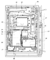
図1は、本実施形態におけるパチンコ遊技機の正面図であり、主要部材の配置レイアウトを示す。本実施形態におけるパチンコ遊技機としては、プリペイドカードによって球貸しを行うカードリーダ(CR:Card Reader)式のパチンコ遊技機であるが、例えば、一般電役機やパチコンと呼ばれる確率設定機能付き弾球遊技機等であっても構わない。さらには、プリペイドカードによって球貸しを行うCR式パチンコ遊技機だけではなく、現金によって球貸しを行うパチンコ遊技機にも適用可能である。 FIG. 1 is a front view of a pachinko gaming machine according to the present embodiment and shows an arrangement layout of main members. The pachinko gaming machine in the present embodiment is a card reader (CR: Card Reader) type pachinko gaming machine that lends a ball using a prepaid card. For example, a bullet ball with a probability setting function called a general electric machine or a pachinko machine. It may be a gaming machine or the like. Furthermore, it is applicable not only to a CR-type pachinko gaming machine that lends a ball with a prepaid card, but also to a pachinko gaming machine that lends a ball with cash.
パチンコ遊技機(遊技機)1は、大別して、遊技盤面を構成する遊技盤(ゲージ盤)2と、遊技盤2を支持固定する遊技機用枠(台枠)3と、から構成されている。
A pachinko gaming machine (gaming machine) 1 is roughly divided into a gaming board (gauge board) 2 constituting a gaming board surface and a gaming machine frame (base frame) 3 for supporting and fixing the
遊技盤2には、ガイドレールによって囲まれた、ほぼ円形状の遊技領域が形成されている。遊技領域のほぼ中央位置には、可変表示装置4が設けられている。可変表示装置4の側部には、通過ゲート5が設けられている。可変表示装置4の下側には、普通可変入賞球装置(始動入賞口)6が配置されている。普通可変入賞球装置6の下側には、特別可変入賞球装置(大入賞口)7が配置されている。また、可変表示装置4の上部には、普通図柄表示器40が設けられている。
The
可変表示装置4は、複数の変動表示部により識別情報としての図柄を変動表示するLCD(Liquid Crystal Display)モジュール等を備えて構成され、例えば、普通可変入賞球装置6に遊技球が入賞することが実行条件となる可変表示ゲーム(特図ゲーム)において、数字、文字、図柄等から構成される3つの表示図柄(特別図柄)の変動表示を開始し、一定時間が経過すると、左、右、中の順で表示図柄を確定する。そして、確定した表示図柄(確定図柄)の組合せが所定の特定表示結果(大当り)となったときに、このパチンコ遊技機1は、特定遊技状態(大当り遊技状態)となる。可変表示装置4には、普通可変入賞球装置6に入った有効入賞球数すなわち始動記憶数を表示する4つの始動記憶表示エリアが設けられていてもよい。
The
また、可変表示装置4は、この他にも、必要に応じて、パチンコ遊技機1の状態に状態に基づく種々の情報を表示する。例えば、余剰球受皿32が満タンである満タン状態や、払い出すべき遊技球が足りない球切状態になったりして、パチンコ遊技機1が払い出すべき遊技球を払い出すことができない場合に、可変表示装置4はその旨を報知するための画面を表示する。
In addition to this, the
通過ゲート5は、通過した打球を球出口を経て普通可変表示装置6の方に導くものである。通過ゲート5と球出口との間の通路には、通過ゲート5を通過した打球を検出するゲートスイッチ21(図5)が設けられている。
The passing
普通図柄表示器40は、発光ダイオード(LED)等を備えて構成され、通過ゲート5のいずれかを遊技球が通過することを始動条件とする普通図ゲームにおいて、点灯、点滅、発光色などが制御される。この普通図ゲームにおいて所定の当りパターンで表示が行われると、普通図ゲームにおける表示結果が「当り」となり、普通可変入賞球装置6を構成する電動チューリップの可動翼片を所定時間が経過するまで傾動制御する。
The
普通可変入賞球装置6は、ソレノイド81(図5)によって垂直(通常開放)位置と傾動(拡大開放)位置との間で可動制御される一対の可動翼片を有するチューリップ型役物(普通電動役物)として構成される。普通可変入賞球装置6に入った入賞球は、遊技盤2の背面に導かれ、始動口スイッチ22(図5)によって検出される。
The normal variable winning
特別可変入賞球装置7は、ソレノイド82(図5)によって入賞領域を開成・閉成制御する開閉板を備える。この開閉板は、通常時には閉成し、普通可変入賞球装置6への遊技球の入賞に基づいて、可変表示装置4による特図ゲームが行われた結果、特定遊技状態となった場合に、ソレノイド82によって入賞領域を所定期間(例えば、29秒)あるいは所定個数(例えば、10個)の入賞球が発生するまで開成(開成サイクル)する状態となるように設定され、その開成している間に遊技盤2の表面を落下する遊技球を受け止める。そして、この開成サイクルを最高16回繰り返すことができるようになっている。
The special variable winning
開閉板から遊技盤2の背面に導かれた入賞球のうち一方(Vゾーン)に入った入賞球は、V入賞スイッチ23(図5)によって検出される。また、開閉板からの入賞球は、カウントスイッチ24(図5)によって検出される。入賞球の検出に応答し、後述する主基板11と払出制御基板15(図2、図5)とにより、所定数の賞球の払出が行われる。
Of the winning balls guided to the back of the
遊技盤2の遊技領域には、複数の入賞口20a〜20dが設けられている。遊技球のそれぞれの入賞口20a〜20dへの入賞は、対応して設けられている入賞口スイッチ25a〜25d(図5)によって検出される。また、遊技盤2の遊技領域には、上記した構成以外にも、装飾ランプを内蔵した風車やアウト口等が設けられている。
In the game area of the
また、遊技領域の外側の左右上部には、効果音を発する2つのスピーカ8L,8Rが設けられている。遊技領域の外周には、点灯又は点滅する遊技効果ランプ9が設けられている。
Two
遊技領域の下部表面には、打球供給皿(上皿)31が設けられている。打球供給皿31の下部には、遊技者が遊技球を発射させるために操作する打球操作ハンドル(操作ノブ)30と、打球供給皿31に収容しきれない遊技球を貯留する余剰球受皿32と、が設けられている。
A hit ball supply tray (upper plate) 31 is provided on the lower surface of the game area. Below the hitting
余剰球受皿32の左下部には枠ボタン19が設けられている。枠ボタン19は、遊技中に所定の条件下で押されることにより、遊技演出の一部を任意に変更させて、遊技効果を高めるために用いられるものである。例えば、所定の条件下で枠ボタン19が押された場合に可変表示装置4において変動表示される図柄を通常とは異なる図柄に変更させることができる。枠ボタン19が押されたことは、枠ボタンスイッチ28(図5)によって検出される。
A
さらに、図1には、パチンコ遊技機1に隣接して設置され、プリペイドカードが挿入されることによって球貸しを可能にするプリペイドカードユニット(以下、カードユニットという)70も示されている。カードユニット70には、使用可能状態であるか否かを示す使用可表示ランプ、カードユニット70がいずれの側のパチンコ遊技機1に対応しているのかを示す連結台方向表示器、カードユニット70内にカードが投入されていることを示すカード投入表示ランプ、記録媒体としてのカードが挿入されるカード挿入口、およびカード挿入口の裏面に設けられているカードリーダライタの機構を点検する場合にカードユニット70を開放するためのカードユニット錠などが設けられている。
Further, FIG. 1 also shows a prepaid card unit (hereinafter referred to as a card unit) 70 that is installed adjacent to the
図2は、パチンコ遊技機1の背面図である。パチンコ遊技機1の背面上方には、補給球としての遊技球を貯留する貯留タンク41と、貯留タンク41に貯留された遊技球を払出ケース42へ誘導する誘導レール43と、が設けられている。誘導レール43の下流は、カーブ樋を介して2列の球通路44a,44bに連通されている。球通路44a,44bの上流側には、球切スイッチ27が設置されている。球通路44a,44bの下部には、払出装置50(図3)を覆う払出ケース42が固定されている。
FIG. 2 is a rear view of the
球切スイッチ27は、球通路44a,44b内の遊技球の有無を検出するスイッチであって、球切スイッチ27が遊技球を検出しなくなると払出装置50における払出モータ51(図4)の回転を停止して遊技球の払出が不動化される。また、球切スイッチ27は、球通路44a,44bに27〜28個の遊技球が存在することを検出できるような位置に係止片によって係止されている。即ち、球切スイッチ27は、球貸の一単位の最大払出量(この実施の形態では100円:25個)以上が確保されていることが確認できるような位置に設置されている。
The ball switch 27 is a switch for detecting the presence or absence of a game ball in the
また、パチンコ遊技機1の背面下方にて打球供給皿31と余剰球受皿32の間を連通する余剰球通路の側壁には、満タンスイッチ26が設けられている。満タンスイッチ26は、余剰球受皿32の満タンを検出するものである。
A
賞球又は球貸要求に基づく遊技球が多数払い出されて、打球供給皿31が満杯になり、遊技球が連絡口に到達した後、さらに遊技球が払い出されると、遊技球は、余剰球通路を経て余剰球受皿32へと導かれる。さらに遊技球が払い出されると、感知レバーが満タンスイッチ26を押圧してオンする。この状態では、払出装置50内の払出モータ51の回転が停止して払出装置50の払出動作が停止すると共に発射装置60の駆動も停止する。
When a lot of game balls based on award balls or ball lending requests are paid out and the hitting
図3は、払出ケース42で覆われた払出装置50を示す正面図(図3(a))及び断面図(図3(b))である。図4は、払出装置50の構成例を示す分解斜視図である。この例では、払出ケース42としての3つのケース45a,45b及び45cの内部に払出装置50が形成されている。ケース45a及び45bの上部には、それぞれ球通路44a,44bと連通する穴46a,46bが設けられており、遊技球は、この穴46a,46bから払出装置50へと流入する。
FIG. 3 is a front view (FIG. 3A) and a cross-sectional view (FIG. 3B) showing the dispensing
払出装置50は、賞球又は球貸し要求に基づく遊技球を払い出すものであり、駆動源となる払出用ステッピングモータ(払出モータ)51を備えている。払出モータ51は、払出制御基板15から送られる駆動信号により、その回転動作が制御される。
The
また、払出装置50には、払出モータ51の回転軸に嵌合しているギア52と、ギア52と噛み合うギア53と、ギア53の中心軸に嵌合して球載置部を有するカム54と、カム54の下方の球通路55と、が設けられている。穴46a,46bから流入した遊技球は、カム54の球載置部が1/3回転する毎に1個ずつ交互に、球通路55を経て落下する。
Further, the
払出装置50には、発光素子(LED)と受光素子とから構成される払出モータ位置センサ71が設けられている。払出モータ位置センサ71は、払出モータ51の回転位置を検出するためのセンサであり、払出モータ51が1/3回転する毎にオンし、所定の検出信号を払出制御基板15に送信する。これにより、払出制御基板15の側では、払出モータ51の回転動作量をカウントすることができる。
The
払出装置50の下方には、例えば近接スイッチによる払出カウントスイッチ72が設けられている。払出カウントスイッチ72は、払出装置50から1個の遊技球が落下する毎にオンして、所定の検出信号を払出制御基板15に送信する。これにより、払出制御基板15の側では、払出装置50から実際に払い出された遊技球の数をカウントすることができる。
Below the
図2に示す発射装置60は、駆動源となる発射用ステッピングモータ(発射モータ)61(図5)を備え、発射モータ61の回転により発射バネを弾性変形させ、発射バネの付勢力を打撃ハンマに伝達して遊技球を打撃することにより、遊技球を遊技領域に向けて発射する。発射バネの弾性力は、操作ノブ30(図5)の操作量に従って調整される。すなわち、遊技球は、操作ノブ30の操作量に応じた速度で発射される。また、発射モータ61は、発射制御基板17から送られる発射駆動信号により、回転動作が制御される。
A launching
また、パチンコ遊技機1の背面には、電源基板10、主基板11、演出制御基板12、音声制御基板13、ランプ制御基板14、払出制御基板15、情報端子基板16、発射制御基板17及び中継基板18といった主要基板がそれぞれ適所に配設されている。
Further, on the back of the
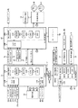
図5は、主基板11、演出制御基板12及び払出制御基板15を中心としたシステム構成例を示すブロック図である。なお、図5には、電源基板10、情報端子基板16、発射制御基板17及び中継基板18も示されている。
FIG. 5 is a block diagram showing a system configuration example centering on the
電源基板10は、パチンコ遊技機1内の各回路に所定の電源電圧を供給するものである。
中継基板18は、主基板11と演出制御基板12との間に接続され、両基板間の通信を中継するものである。具体的には、中継基板18は、主基板11から演出制御基板12へ送信される信号の伝達を中継し、逆に演出制御基板12から主基板11へ送信される信号の伝達を阻止するものである。
The
The
主基板11は、遊技制御用マイクロコンピュータ110、スイッチ回路115やソレノイド回路116等を搭載して構成される。また、主基板11には、演出制御基板12及び払出制御基板15への配線やゲートスイッチ21、始動口スイッチ22、V入賞スイッチ23、カウントスイッチ24及び入賞口スイッチ25a〜25dからの配線が接続されている。さらに、主基板11には、普通可変入賞球装置6における可動翼片の可動制御や特別可変入賞球装置7における開成・閉成制御を行うためのソレノイド81,82への配線も接続されている。
The
遊技制御用マイクロコンピュータ110は、例えば1チップマイクロコンピュータであり、ゲーム制御用のプログラム等を記憶するROM(Read Only Memory)111、ワークメモリとして使用されるRAM(Random Access Memory)112、プログラムに従って制御動作を行うCPU(Central Processing Unit)113及びI/O(Input/Output)ポート114を含んでいる。この遊技制御用マイクロコンピュータ110は、特図ゲームにおいて用いる乱数の生成機能や、演出制御基板12及び払出制御基板15に対し、それぞれ指令情報の一例となる制御コマンドを出力して送信する機能等を有するものである。
The
主基板11から払出制御基板15へ送信される制御コマンドは払出制御コマンドであり、主基板11から中継基板18を介して演出制御基板12へ送信される制御コマンドは演出制御コマンドである。この実施の形態において、払出制御コマンドは、払出制御信号CD0〜CD7の8本の信号線で主基板11から払出制御基板15へ送信され、演出制御コマンドは、演出制御信号CD0〜CD7の8本の信号線で主基板11から演出制御基板12へ送信される。また、ストローブ信号を送信するために、主基板11と払出制御基板15との間には払出制御INT信号の信号線が配線され、主基板11と演出制御基板12との間には中継基板18を介して演出制御INT信号の信号線が配線されている。
The control command transmitted from the
さらに、主基板11には、払出制御基板15から出力される遊技球の払い出しができない状態であることを示す払出エラー信号を受信するための信号線が配線されている。本実施の形態では、払出制御基板15は、満タン状態又は球切状態の場合に遊技球の払い出しができない状態であるとして、払出エラー信号としての満タン状態信号又は球切状態信号を主基板11に対して出力する。
Furthermore, a signal line for receiving a payout error signal indicating that the game ball output from the
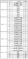
図6は、この実施の形態で用いられる主基板11から払出制御基板15及び演出制御基板12に対して送出される払出制御コマンド及び演出制御コマンドの内容の一例を示す説明図である。
図6(a)に示すように、各制御コマンドは2バイト構成であり、1バイト目はMODE(コマンドの分類)を表し、2バイト目はEXT(コマンドの種類)を表す。MODEデータの先頭ビットは必ず「1」とされ、EXTデータの先頭ビットは「0」とされる。
FIG. 6 is an explanatory diagram showing an example of the contents of payout control commands and effect control commands sent from the
As shown in FIG. 6A, each control command has a 2-byte configuration, the first byte represents MODE (command classification), and the second byte represents EXT (command type). The first bit of MODE data is always “1”, and the first bit of EXT data is “0”.
図6(b)に示す払出制御コマンドの例において、コマンドF0XX(h)は、賞球個数を指定する払出制御コマンドである。なお、このEXTデータのXX(h)は不特定の16進数であり、払出個数を示している。 In the example of the payout control command shown in FIG. 6B, the command F0XX (h) is a payout control command for designating the number of prize balls. Note that XX (h) of this EXT data is an unspecified hexadecimal number and indicates the number of payouts.
図6(c)に示す演出制御コマンドの例において、コマンド80XX(h)は、可変表示装置4における特別図柄の可変表示を開始する旨を指示するための可変表示開始コマンドである。なお、このEXTデータのXX(h)は不特定の16進数であり、演出制御コマンドによる指示内容に応じて任意に設定される値であるものとする。演出制御基板12の側では、可変表示開始コマンドに含まれるEXTデータに対応して、特別図柄の総可変表示時間、可変表示の表示結果が大当り組合せの特定表示結果になるか否かの判定結果やリーチとするか否かの判定結果などを特定することができる。
In the example of the effect control command shown in FIG. 6C, the command 80XX (h) is a variable display start command for instructing to start variable display of the special symbol on the
コマンド90XX(h)、91XX(h)、及び92XX(h)は、特別図柄の左、中、右確定図柄を指定する特別図柄指定コマンドである。各特別図柄指定コマンドでは、XX(h)に特別図柄の図柄番号が設定される。コマンドA000(h)は、特別図柄の可変表示の終了を指示する特別図柄確定コマンドである。コマンドB000(h)は、大当り遊技状態の終了を指示する大当り終了コマンドである。 Commands 90XX (h), 91XX (h), and 92XX (h) are special symbol designation commands for designating the left, middle, and right fixed symbols of the special symbols. In each special symbol designation command, the symbol number of the special symbol is set in XX (h). Command A000 (h) is a special symbol confirmation command for instructing the end of variable symbol variable display. Command B000 (h) is a jackpot end command for instructing the end of the jackpot gaming state.
コマンドC000(h)は、余剰球受皿32が満タンであるために遊技球を払い出すことができないことの報知を指示する満タン報知コマンドであり、コマンドC0001(h)は、満タン報知コマンドに基づき実行されている満タン報知の解除を指示する満タン報知解除コマンドである。
コマンドC002(h)は、球切れが生じているために遊技球を払い出すことができないことの報知を指示する球切報知コマンドであり、コマンドC003(h)は、球切報知コマンドに基づき実行されている球切報知の解除を指示する球切報知解除コマンドである。
The command C000 (h) is a full tank notification command for instructing that the game ball cannot be paid out because the surplus
The command C002 (h) is a ball-cutting notification command for instructing that a game ball cannot be paid out because a ball has run out. The command C003 (h) is executed based on the ball-cutting notification command. This is a ball-cutting notification release command for instructing cancellation of the ball-cutting notification being made.
図7は、遊技制御用マイクロコンピュータ110の構成例の詳細を示すブロック図である。遊技制御用マイクロコンピュータ110は、図7に示すように、スイッチタイマメモリ211と、スイッチオン判定値テーブルメモリ212と、フラグメモリ213と、コマンド送信テーブルメモリ214と、を備えている。
FIG. 7 is a block diagram showing details of a configuration example of the
スイッチタイマメモリ211は、各種スイッチから入力される検出信号がオン状態にあるか或いはオフ状態にあるかに応じて、加算又はクリアされるスイッチタイマを複数記憶するものである。この実施の形態においては、図8に示すように、各種スイッチに対応したアドレスにスイッチタイマが、それぞれ設けられている。
The
図7に示すスイッチオン判定値テーブルメモリ212は、各種スイッチがオンしているか否かを判定するためのスイッチオン判定値を複数記憶するものである。具体的には、各種スイッチから入力される検出信号がオン状態にあると連続して判定される回数がスイッチオン判定値として記憶されている。
The switch-on determination
この実施の形態においては、図9に示すように、入賞口スイッチ25a〜25d、ゲートスイッチ21、始動口スイッチ22、カウントスイッチ24、V入賞スイッチ23のスイッチオン判定値として「2」が設定されている。従って、各種スイッチ用のスイッチタイマの値が「2」になると、各種スイッチがオンしていると判定される。
In this embodiment, as shown in FIG. 9, “2” is set as the switch-on determination value of the winning opening switches 25a to 25d, the gate switch 21, the
図7に示すフラグメモリ213は、パチンコ遊技機1における遊技の進行を制御するために用いられる複数種類のフラグを設定するためのものである。例えば、フラグメモリ213には、特別図柄プロセスフラグ、普通図柄プロセスフラグ、スイッチオンフラグ、満タン状態フラグ、球切状態フラグ及びタイマ割込フラグ等が設けられている。
The
特別図柄プロセスフラグは、特別図柄プロセス処理(図24のステップS15)において、どの処理を選択・実行すべきかを指示する。普通図柄プロセスフラグは、普通図柄表示器40の表示状態を所定の順序で制御するために、普通図柄プロセス処理(図24のステップS16)において、どの処理を選択・実行すべきかを指示する。
The special symbol process flag indicates which process should be selected and executed in the special symbol process (step S15 in FIG. 24). The normal symbol process flag indicates which process should be selected and executed in the normal symbol process (step S16 in FIG. 24) in order to control the display state of the
スイッチオンフラグは、スイッチタイマメモリ211に記憶されているタイマ値等に応じて、各々セットあるいはクリアされる複数ビットからなるフラグである。
満タン状態フラグは、払出制御基板15から満タン状態信号の入力があるときにオンされ、入力がないときにオフされるフラグである。球切状態フラグは、払出制御基板15から球切状態信号の入力があるときにオンされ、入力がないときにオフされるフラグである。
タイマ割込フラグは、所定時間が経過してタイマ割込みが発生するごとにオン状態にセットされる。
The switch-on flag is a flag composed of a plurality of bits that are set or cleared in accordance with a timer value or the like stored in the
The full tank state flag is a flag that is turned on when a full tank state signal is input from the
The timer interrupt flag is set to the on state every time a predetermined time elapses and a timer interrupt is generated.
コマンド送信テーブルメモリ214には、主基板11からサブ側の各制御基板(演出制御基板12及び払出制御基板15)に出力する各制御コマンドについて、複数のコマンド送信テーブルが設けられている。図10(a)は、コマンド送信テーブルメモリ214の構成例を示す図である。1つのコマンド送信テーブルは3バイトで構成され、1バイト目には、INTデータが設定されている。また、2バイト目のコマンドデータ1には、MODEデータが設定されており、3バイト目のコマンドデータ2には、EXTデータが設定されている。
The command
なお、EXTデータそのものがコマンドデータ2の領域に設定されてもよいが、コマンドデータ2には、EXTデータが格納されているテーブルのアドレスを指定するためのデータが設定されるようにしてもよい。例えば、コマンドデータ2のビット7(ワークエリア参照ビット)が0であれば、コマンドデータ2にEXTデータそのものが設定されていることを示す。そのようなEXTデータはビット7が0であるデータである。この実施の形態では、ワークエリア参照ビットが1であれば、EXTデータとして、送信バッファの内容を使用することを示す。なお、ワークエリア参照ビットが1であれば、他の7ビットが、EXTデータが格納されているテーブルのアドレスを指定するためのオフセットであることを示すように構成することもできる。
Although the EXT data itself may be set in the area of the
図10(b)は、INTデータの構成例を示す図である。INTデータのビット0は、払出制御基板15に払出制御コマンドを送出すべきか否かを示すものである。ビット0が「1」であるならば、払出制御コマンドを送出すべきことを示す。従って、CPU113は、例えば賞球処理(図24のステップS20)において、INTデータに「01(h)」を設定する。また、INTデータのビット1は、演出制御基板12に演出制御コマンドを送出すべきか否かを示すものである。ビット1が「1」であるならば、演出制御コマンドを送出すべきことを示す。従って、CPU113は、例えばエラー処理(図24のステップS12)やコマンド制御処理(図24のステップS17)において、INTデータに「02(h)」を設定する。
FIG. 10B is a diagram illustrating a configuration example of INT data.
また、コマンド送信テーブルメモリ214には、図10(c)に示すように、払出制御コマンドに対して、リングバッファ及び送信バッファが設けられている。賞球処理において、賞球払出条件が成立すると、成立した条件に応じた賞球個数が順次リングバッファに設定される。また、賞球個数に関する払出制御コマンドを送出する際に、リングバッファから1個のデータが送信バッファに転送される。
In addition, as shown in FIG. 10C, the command
なお、図10(c)に示す例において、リングバッファは、12個のバッファから構成されており、12個分の払出制御コマンドに相当するデータを格納することができる。リングバッファには、入賞口の数に対応したバッファ数が設けられているため、同時に入賞が発生した場合であっても、それぞれの入賞に基づく払出制御コマンドのデータを格納することができる。 In the example shown in FIG. 10C, the ring buffer is composed of 12 buffers, and can store data corresponding to 12 payout control commands. Since the number of buffers corresponding to the number of winning openings is provided in the ring buffer, it is possible to store payout control command data based on each winning even when winning simultaneously occurs.
図11及び図12は、I/Oポート114のビット割当を示す説明図である。図11に示すように、入力ポート0のビット0〜7には、それぞれ、入賞口スイッチ25a〜25d、ゲートスイッチ21、始動口スイッチ22、カウントスイッチ24及びV入賞スイッチ23の検出信号が入力される。また、入力ポート1のビット0及び1には、それぞれ、払出制御基板15から出力される満タン状態信号、球切状態信号が入力される。
11 and 12 are explanatory diagrams showing bit allocation of the I /
図12に示すように、出力ポート0からは、払出制御コマンド及び演出制御コマンドのINT信号が、それぞれ払出制御基板15及び演出制御基板12に対して出力される。出力ポート1からは、払出制御コマンドの8ビットデータが払出制御基板15に対して出力され、出力ポート2からは、演出制御コマンドの8ビットデータが演出制御基板12に対して出力される。
As shown in FIG. 12, from the
また、出力ポート3からは、普通可変入賞球装置6における可動翼片の可動制御を行うためのソレノイド81及び特別可変入賞球装置7における開成・閉成制御を行うためのソレノイド82に対する駆動信号がそれぞれ出力される。
Further, from the
図5に示すスイッチ回路115は、ゲートスイッチ21、始動口スイッチ22、V入賞スイッチ23、カウントスイッチ24、入賞口スイッチ25a〜25dからの検出信号を取り込んで、遊技制御用マイクロコンピュータ110に伝達するものである。
ソレノイド回路116は、遊技制御用マイクロコンピュータ110からの指令に従って各ソレノイド81,82を駆動する。ソレノイド81は、リンク機構を介して普通可変入賞球装置6の可動翼片に連結されている。ソレノイド82は、リンク機構を介して特別可変入賞球装置7の開閉板に連結されている。
The
The
図5に示す払出制御基板15は、主基板11、情報端子基板16及び発射制御基板17と配線接続されている。また、払出制御基板15には、払出モータ位置センサ71、払出カウントスイッチ72、満タンスイッチ26及び球切スイッチ27からの検出信号が入力される。さらに、払出制御基板15には、払出モータ51及びカードユニット70への配線が接続されている。
The
払出制御基板15には、払出制御用マイクロコンピュータ150やスイッチ回路155等が搭載されており、払出制御用マイクロコンピュータ150は賞球や球貸要求に基づく遊技球等の払出制御を行う。払出制御用マイクロコンピュータ150は、例えば1チップマイクロコンピュータであり、払出制御用のプログラム等を記憶するROM151、ワークメモリとして使用されるRAM152、プログラムに従って払出制御動作を行うCPU153及びI/Oポート154を含んでいる。
The
図13は、払出制御用マイクロコンピュータ150の構成例の詳細を示すブロック図である。払出制御用マイクロコンピュータ150は、図13に示すように、受信コマンドバッファメモリ251と、スイッチタイマメモリ252と、スイッチオン判定値テーブルメモリ253と、払出動作量カウンタ254と、賞球総数カウンタ255と、貸球総数カウンタ256と、払出中受信個数カウンタ257と、フラグメモリ258と、を備えている。
FIG. 13 is a block diagram showing details of a configuration example of the
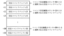
受信コマンドバッファメモリ251は、主基板11から受信した払出制御コマンドを格納するための受信コマンドバッファが複数設けられているものである。図14に示す例では、12個の受信コマンドバッファが設けられており、受信したコマンドを格納する受信コマンドバッファは、コマンド受信個数カウンタで指定される。コマンド受信個数カウンタは、0〜11の範囲の値をとる。各受信コマンドバッファは、例えば1バイトで構成され、複数の受信コマンドバッファをリングバッファとして使用することにより、2バイト構成の払出制御コマンドを6個格納することができる。
The reception
図13に示すスイッチタイマメモリ252は、払出モータ位置センサ71、払出カウントスイッチ72、満タンスイッチ26及び球切スイッチ27から入力される検出信号がオン状態にあるか或いはオフ状態にあるかに応じて、各々加算又はクリアされるスイッチタイマを複数記憶するものである。この実施の形態においては、図15に示すように、センサ及び各種スイッチに対応したアドレスにスイッチタイマが、それぞれ設けられている。
The
図13に示すスイッチオン判定値テーブルメモリ253は、センサ及び各種スイッチがオンしているか否かを判定するためのスイッチオン判定値を複数記憶するものである。具体的には、センサ及び各種スイッチから入力される検出信号がオン状態にあると連続して判定される回数がスイッチオン判定値として記憶されている。 The switch-on determination value table memory 253 shown in FIG. 13 stores a plurality of switch-on determination values for determining whether or not the sensor and various switches are turned on. Specifically, the number of times that the detection signal input from the sensor and various switches is continuously determined to be in the on state is stored as a switch-on determination value.
この実施の形態においては、図16に示すように、払出モータ位置センサ71及び払出カウントスイッチ72のスイッチオン判定値として「2」が、満タンスイッチ26のスイッチオン判定値として「50」が、球切スイッチ27のスイッチオン判定値として「250」が、それぞれ設定されている。また、スイッチオン判定値テーブルメモリ253には、球切スイッチ27がオフしているか否かを判定するためのスイッチオフ判定値として「30」が設定されている。
In this embodiment, as shown in FIG. 16, “2” is set as the switch-on determination value of the payout
図13に示す払出動作量カウンタ254は、球貸制御処理(図34のステップS54)や賞球制御処理(図34のステップS55)において設定された遊技球の個数を、払出モータ51が1/6回転する毎に、1ずつ減算して行くダウンカウンタである。カードユニット70から球貸要求の信号を受信すると、この払出動作量カウンタ254には、球貸制御処理において1単位(例えば25個)の貸球の個数が設定される。また、賞球制御処理においては、払出動作量カウンタ254には、賞球総数カウンタ255に記憶されている賞球の個数が設定される。
The payout
そして、この払出動作量カウンタ254の値は、払出モータ51が1/3回転したことを払出モータ位置センサ71が検出する毎に、即ち、払出モータ51が1個の遊技球を払い出すための回転動作(払出動作)を実行する毎に、1ずつ減算されて行く。このようにして、払出動作量カウンタ254は、払出モータ51の払出動作量を計数することができる。
The value of the payout
賞球総数カウンタ255は、払出装置50から払い出される賞球の総数を記憶するためのものである。主基板11から払出制御コマンドを受信する毎に、この賞球総数カウンタ255の値には、受信した払出制御コマンドにより指定される賞球の個数が加算される。そして、賞球総数カウンタ255の値は、払出カウントスイッチ72が払出装置50から払い出された賞球を検出する毎に、1ずつ減算されて行く。このようにして、賞球総数カウンタ255は、払出装置50から実際に払い出された賞球の個数をカウントして行くことができる。
The prize ball
貸球総数カウンタ256は、払出装置50から払い出される貸球の総数を記憶するためのものである。カードユニット70から球貸要求の信号を受信する毎に、この貸球総数カウンタ256の値には、1単位の貸球の個数が加算される。そして、貸球総数カウンタ256の値は、払出カウントスイッチ72が払出装置50から払い出された貸球を検出する毎に、1ずつ減算されて行く。このようにして、貸球総数カウンタ256は、払出装置50から実際に払い出された貸球の個数をカウントして行くことができる。
The total
払出中受信個数カウンタ257は、賞球の払出中に受信した払出制御コマンドによって指定される遊技球の個数を記憶するためのものである。主基板11から賞球個数を指定する払出制御コマンドを受信する毎に、払出中受信個数カウンタ257の値には、受信した払出制御コマンドにより指定される賞球の個数が加算される。その後、賞球制御処理(図34のステップS55)において、払出動作量カウンタ254には、払出中受信個数カウンタ257の値が、最大払出数(この実施の形態では25個)を超えない限度で加算され、払出中受信個数カウンタ257からは、この払出動作量カウンタ254に加算された値が減算される。
The during-payout received
フラグメモリ258は、払出装置50の払出動作を制御するために用いられる複数種類のフラグを設定するためのものである。例えば、フラグメモリ258には、スイッチオンフラグ、満タンフラグ、球切フラグ、払出中受信フラグ、賞球払出中フラグ、貸球払出中フラグ及びタイマ割込フラグ等が設けられている。
The
スイッチオンフラグは、スイッチタイマメモリ252に記憶されているタイマ値等に応じて、各々セットあるいはクリアされる複数ビットからなるフラグである。
満タンフラグは、満タンスイッチ26に割り当てられているスイッチオンフラグのビットのオン/オフに応じて、セットあるいはクリアされるフラグである。球切フラグは、球切スイッチ27に割り当てられているスイッチオンフラグのビットのオン/オフに応じて、セットあるいはクリアされるフラグである。
払出中受信フラグは、賞球の払出中に、賞球個数を指定する払出制御コマンドを受信したときにオン状態にセットされ、払出中受信個数カウンタ257に記憶されている賞球個数が「0」になったことに応じてオフされるフラグである。
The switch-on flag is a flag composed of a plurality of bits that are set or cleared according to a timer value or the like stored in the
The full tank flag is a flag that is set or cleared in accordance with ON / OFF of the bit of the switch on flag assigned to the
The payout receiving flag is set to ON when a payout control command for designating the number of prize balls is received during the payout of winning balls, and the number of prize balls stored in the payout received
賞球払出中フラグは、払出装置50による賞球の払出動作が実行されているときにオン状態にセットされ、賞球の払出動作を終了するとオフされるフラグである。貸球払出中フラグは、払出装置50による貸球の払出動作が実行されているときにオン状態にセットされ、貸球の払出動作を終了するとオフされるフラグである。タイマ割込フラグは、所定時間が経過してタイマ割込みが発生するごとにオン状態にセットされる。
The winning ball paying-out flag is a flag that is set to ON when the paying-out operation of the winning ball by the paying
図17及び図18は、I/Oポート154のビット割当を示す説明図である。図17に示すように、入力ポート0のビット0には、主基板11からの払出制御コマンドのINT信号が入力される。入力ポート1には、主基板11からの払出制御コマンドの8ビットデータが入力される。入力ポート2のビット0〜3には、それぞれ、払出モータ位置センサ71、払出カウントスイッチ72、満タンスイッチ26及び球切スイッチ27の検出信号が入力される。
17 and 18 are explanatory diagrams showing bit allocation of the I /
図18に示すように、出力ポート0のビット0〜3からは、払出モータ51を駆動するための信号が出力される。この出力信号である払出モータφ1〜4は、ステッピングモータである払出モータ51の励磁パターンを表す信号である。出力ポート0のビット4からは、発射制御基板17に対する発射制御信号が出力される。この発射制御信号は、例えばカードユニット70が払出制御基板15に接続されていないような発射モータ61を駆動させるべきでない場合に出力され、発射モータ61の駆動を停止させる。
As shown in FIG. 18, a signal for driving the
出力ポート1のビット0及び1からは、満タン信号及び球切信号が、それぞれ主基板11に対して出力される。満タン信号はフラグメモリ258において満タンフラグがセットされているときに出力される信号であり、球切信号は球切フラグがセットされているときに出力される信号である。
From
なお、その他の出力ポートからは、例えば、各種情報出力用信号が情報端子基板16に対して出力される。また、払出制御基板15とカードユニット70との間の通信も入力ポート及び出力ポートを介して行われる。
For example, various information output signals are output from the other output ports to the
図5に示すスイッチ回路155は、払出モータ位置センサ71、払出カウントスイッチ72、満タンスイッチ26及び球切スイッチ27からの検出信号を取り込んで、払出制御用マイクロコンピュータ150に伝達するものである。
The
情報端子基板16は、払出制御基板15から出力される各種遊技関連情報を外部に出力するためのものである。例えば、情報端子基板16には、少なくとも、球切スイッチ27の出力を導入して外部出力するための球切用端子、賞球情報(賞球個数信号)を外部出力するための賞球用端子及び球貸情報(球貸個数信号)を外部出力するための球貸用端子が設けられている。
The
発射制御基板17は、払出制御基板15からの発射制御信号及び操作ノブ30の操作量に応じて、発射装置60による発射動作を制御するためのものである。発射制御基板17には、払出制御基板15及び操作ノブ30からの配線が接続されると共に発射モータ61への配線が接続されている。発射制御基板17は、操作ノブ30の操作量に従って発射モータ61の駆動力を調整することにより、この操作量に応じた速度で打球を発射する。
The
図5に示す演出制御基板12は、主基板11、音声制御基板13、ランプ制御基板14、可変表示装置4及び普通図柄表示器40と配線接続されている。また、演出制御基板12には、枠ボタンスイッチ28の検出信号が入力される。
The
演出制御基板12には、演出制御用マイクロコンピュータ120やスイッチ回路125等が搭載されており、演出制御用マイクロコンピュータ120は主基板11から中継基板18を介して受信した演出制御コマンドに基づいて演出制御を行う。演出制御用マイクロコンピュータ120は、例えば1チップマイクロコンピュータであり、演出制御用のプログラム等を記憶するROM121、ワークメモリとして使用されるRAM122、プログラムに従って払出制御動作を行うCPU123及びI/Oポート124を含んでいる。
演出制御用マイクロコンピュータ120は、主基板11から出力される演出制御コマンドに基づいて、可変表示ゲームに用いられる画像を可変表示装置4上に表示させると共に、普通図柄表示器40の点灯/消灯制御を行う。また、演出制御用マイクロコンピュータ120は、スピーカ8L,8Rによる音声出力動作や遊技効果ランプ9の点灯/消灯動作を制御する。
The
The
図19は、演出制御用マイクロコンピュータ120の構成例の詳細を示すブロック図である。演出制御用マイクロコンピュータ120は、図19に示すように、受信コマンドバッファメモリ221と、演出制御パターン決定用テーブルメモリ222と、フラグメモリ223と、各種タイマ224と、を備えている。
FIG. 19 is a block diagram showing details of a configuration example of the
受信コマンドバッファメモリ221は、主基板11から受信した演出制御コマンドを格納するための受信コマンドバッファが複数設けられているものである。受信コマンドバッファメモリ221の構成例は、図14に示した払出制御用マイクロコンピュータ150における受信コマンドバッファメモリ251の構成例と同じであるので、その説明を省略する。
The reception
演出制御パターン決定用テーブルメモリ222は、主基板11から受けた演出表示制御コマンドに基づいて選択される複数の演出制御パターン決定用テーブルを記憶する。具体的には、演出制御パターン決定用テーブルメモリ222は、図20に示すように、図柄表示制御パターン決定用テーブル225を含んで構成される。
The effect control pattern
図20に示す図柄表示制御パターン決定用テーブル225は、複数種類の図柄表示制御パターンを格納する。主基板11から演出制御基板12に対して送出される可変表示開始コマンドは、図柄表示制御パターン決定用テーブル225に格納されている図柄表示制御パターンを、EXTデータにより指定する。従って、演出制御用マイクロコンピュータ120は、主基板11から可変表示開始コマンドを受信すると、指定された図柄表示制御パターンに基づいて、可変表示装置4における図柄の表示を制御する。
The symbol display control pattern determination table 225 shown in FIG. 20 stores a plurality of types of symbol display control patterns. The variable display start command sent from the
図柄表示制御パターン決定用テーブル225に格納されている図柄表示制御パターンのうち通常Aハズレ図柄表示制御パターン及び通常Bハズレ図柄表示制御パターンは、可変表示装置4による特図ゲームにてリーチとすることなくハズレの確定図柄を導出表示する可変表示パターンである。通常Aハズレ図柄表示制御パターンと通常Bハズレ図柄表示制御パターンとは、可変表示態様が異なっており、例えば、特別図柄の可変表示速度や回転方向が異なる。
Of the symbol display control patterns stored in the symbol display control pattern determination table 225, the normal A lose symbol display control pattern and the normal B lose symbol display control pattern are reached in a special symbol game by the
リーチAハズレ図柄表示制御パターンからリーチDハズレ図柄表示制御パターンは、可変表示装置4による特図ゲームにてリーチとした後に当りとすることなくハズレの確定図柄を導出表示する可変表示パターンであり、それぞれ可変表示態様が異なる。リーチA大当り図柄表示制御パターンからリーチD大当り図柄表示制御パターンは、可変表示装置4による特図ゲームにて特別図柄の可変表示における表示結果を大当りとする可変表示パターンであり、それぞれ可変表示態様が異なる。
Reach A losing symbol display control pattern from reach A losing symbol display control pattern is a variable display pattern for deriving and displaying a fixed symbol of losing without reaching after reaching a special figure game by the
また、図柄表示制御パターン決定用テーブル225は、満タン状態であることを可変表示装置4において報知するために用いられる満タン報知図柄表示制御パターンと、球切状態であることを可変表示装置4において報知するために用いられる球切報知図柄表示制御パターンを格納している。満タン報知図柄表示制御パターンは、主基板11から満タン報知コマンドを受信したときに実行され図柄表示制御パターンであり、球切報知図柄表示制御パターンは、主基板11から球切報知コマンドを受信したときに実行される図柄表示制御パターンである。
In addition, the symbol display control pattern determination table 225 has a full tank notification symbol display control pattern used to notify the
各図柄表示制御パターンは、図21に示すように、図柄表示制御プロセスタイマ設定値、図柄表示制御データなど、特別図柄の表示状態を制御するためのデータからなり、時系列的に特別図柄の可変表示速度や表示する図柄の大きさ、その表示状態での表示期間、キャラクタの切替タイミング等が設定されている。
また、満タン報知図柄表示制御パターンにおける図柄表示制御データは、満タン状態を報知するための専用の図柄を含み、球切報知図柄表示制御パターンにおける図柄表示制御データは、球切状態を報知するための専用の図柄を含んでいる。
As shown in FIG. 21, each symbol display control pattern includes data for controlling the display state of a special symbol, such as a symbol display control process timer set value, symbol display control data, and the like. The display speed, the size of the pattern to be displayed, the display period in the display state, the character switching timing, and the like are set.
Further, the symbol display control data in the full tank notification symbol display control pattern includes a dedicated symbol for notifying the full tank state, and the symbol display control data in the ball cut notification symbol display control pattern reports the ball cut state. Includes a special design for.
図19に示すフラグメモリ223は、可変表示装置4における表示状態や主基板11からのコマンド受信に応じて各々セットあるいはクリアされる複数種類のフラグを設定するためのものである。例えば、フラグメモリ223には、表示制御プロセスフラグ、可変表示開始フラグ、有効フラグ及びタイマ割込フラグ等が設けられている。
A
表示制御プロセスフラグは、後述する特別図柄表示制御プロセス処理(図50)において、どの処理を選択・実行すべきかを指示する。可変表示開始フラグは、主基板11から可変表示開始コマンド80XX(h)を受信したときにオン状態にセットされる。有効フラグは、主基板11から左・中・右図柄指定コマンド90XX(h)、91XX(h)及び92XX(h)を受信したときにオン状態にセットされる。タイマ割込フラグは、所定時間が経過してタイマ割込みが発生するごとにオン状態にセットされる。
The display control process flag indicates which process should be selected / executed in a special symbol display control process (described later) (FIG. 50). The variable display start flag is set to the on state when the variable display start command 80XX (h) is received from the
図19に示す各種タイマ224は、可変表示装置4の表示制御に用いられる複数種類のタイマを含んで構成される。例えば、各種タイマ224は、図柄表示制御プロセスタイマ、可変表示時間タイマや監視タイマを含んでいる。図柄表示制御プロセスタイマは、図21に示す図柄表示制御パターンに設定されている図柄表示制御プロセスタイマ設定値をカウントダウンすることにより、可変表示装置4にて図柄を図柄表示制御パターンに従った態様で可変表示させる可変表示期間を計測する。
各種タイマ224に含まれる可変表示時間タイマは、可変表示装置4による特図ゲームの実行時間である可変表示時間を計測するためのダウンカウンタである。監視タイマは、可変表示時間タイマがタイムアウトしてからの経過時間を計測するためのものである。監視タイマは、主基板11から演出制御コマンドを所定時間以上受信しなかったときにタイムアウトする。
The variable display time timer included in the
図5に示すスイッチ回路125は、枠ボタンスイッチ28からの検出信号を取り込んで、演出制御用マイクロコンピュータ120に伝達するものである。
図5に示す音声制御基板13には、スピーカ8L,8Rを駆動するための駆動回路等が搭載されている。演出制御用マイクロコンピュータ120は、音声制御基板13を介して、スピーカ8L,8Rによる音声出力動作を制御する。
ランプ制御基板14には、遊技効果ランプ9を駆動するための駆動回路が搭載されている。演出制御用マイクロコンピュータ120は、ランプ制御基板14を介して、遊技効果ランプ9の点灯/消灯動作を制御する。
The
The
A drive circuit for driving the
図5に示す中継基板18は、図22に示すように、主基板11と接続するためのコネクタ181と、演出制御基板12と接続するためのコネクタ182と、信号が送信される方向を規制するための信号方向規制部183と、を備えている。
信号方向規制部183は、ダイオード及び抵抗で構成されており、一方向にのみ電流を流すダイオードの性質により、主基板11から演出制御基板12への方向の信号の伝達を中継すると共に、演出制御基板12から主基板11への方向の信号の伝達を阻止する。
As shown in FIG. 22, the
The signal direction restricting unit 183 includes a diode and a resistor, and relays the transmission of the signal in the direction from the
入賞に基づく賞球払出を決定する処理は主基板11により行われる。このため、主基板11に対して不正な信号を入力して、不正に大当りを生じさせて賞球を得ようとする行為が行われることがある。この場合、厳しいセキュリティ規制に基づき設計されている主基板11に直接不正信号を入力するのではなく、主基板11よりセキュリティ規制が緩い演出制御基板12を介して、主基板11に不正信号が入力される可能性がある。
The
例えば、枠ボタンスイッチ28からは演出制御基板12に対して信号を入力することができる。従って、枠ボタンスイッチ28と演出制御基板12との間に不正基板を接続して、演出制御基板12を介して主基板11に不正信号が入力される可能性がある。
For example, a signal can be input from the frame button switch 28 to the
しかし、このような場合であっても、中継基板18の機能により、そのような不正信号が演出制御基板12を介して主基板11に入力されることを防ぐことができる。
また、演出制御基板12に不正基板が接続されていることが疑われる場合であっても、主基板11と演出制御基板12との間に中継基板18が接続されていることを確認することにより、不正基板を探すまでもなく、演出制御基板12から主基板11に不正信号が入力されないことを確認することができる。
このため、図2に示すように、中継基板18は、設置されていることが一目で分かる位置である主基板11のカバー上に配設されている。なお、中継基板の配設位置は、設置されていることが分かる位置であればよく、図2に示す位置に限定されない。
However, even in such a case, the function of the
Even if it is suspected that an illegal board is connected to the
For this reason, as shown in FIG. 2, the
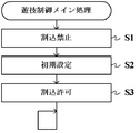
次に、本実施形態におけるパチンコ遊技機1の動作(作用)を説明する。図23は、主基板11に搭載された遊技制御用マイクロコンピュータ110が実行する遊技制御メイン処理を示すフローチャートである。主基板11では、電源基板10からの電源電圧が供給されると、遊技制御用マイクロコンピュータ110が起動し、CPU113は、まず、図23のフローチャートに示す遊技制御メイン処理を実行する。
Next, the operation (action) of the
遊技制御メイン処理を開始すると、CPU113は、割込禁止に設定した後(ステップS1)、必要な初期設定を行う(ステップS2)。この初期設定では、例えば、RAM112がクリアされる。また、遊技制御用マイクロコンピュータ110に内蔵されたCTC(カウンタ/タイマ回路)のレジスタ設定を行うことにより、定期的(例えば、2ミリ秒ごと)にタイマ割込を発生させる。初期設定が終了すると、割込を許可した後(ステップS3)、ループ処理に入る。
When the game control main process is started, the
こうした遊技制御メイン処理の実行により、2ミリ秒ごとに繰り返しタイマ割込が発生するように設定され、タイマ割込が発生すると、CPU113は、図24のフローチャートに示す遊技制御割込処理を実行する。
By executing the game control main process, the timer interrupt is set to repeatedly occur every 2 milliseconds. When the timer interrupt occurs, the
遊技制御割込処理において、CPU113は、図24に示すように、まず、スイッチ回路115を介して、ゲートスイッチ21、始動口スイッチ22、V入賞スイッチ23、カウントスイッチ24、入賞口スイッチ25a〜25dの検出信号を入力し、それらの状態を判定するスイッチ処理を行う(ステップS11)。
In the game control interrupt process, as shown in FIG. 24, the
続いて、CPU113は、所定のエラー処理を実行することにより、パチンコ遊技機1の異常診断を行い、その診断結果に応じて必要ならば警告を発生可能とする(ステップS12)。この後、CPU113は、遊技制御に用いられる大当り判定用の乱数等の各判定用乱数を更新する判定用乱数更新処理(ステップS13)と、表示用乱数を更新する表示用乱数更新処理(ステップS14)と、を順次実行する。
Subsequently, the
次に、CPU113は、特別図柄プロセス処理を実行する(ステップS15)。特別図柄プロセス処理では、遊技状態に応じてパチンコ遊技機1を所定の順序で制御するために、特別図柄プロセスフラグに従って該当する処理が選択されて実行される。特別図柄プロセス処理に続いて、CPU113は、普通図柄プロセス処理を実行する(ステップS16)。普通図柄プロセス処理では、普通図柄表示器40を所定の順序で制御するために、普通図柄プロセスフラグに従って該当する処理が選択されて実行される。
Next, the
さらに、CPU113は、所定のコマンド制御処理を実行することにより、主基板11から演出制御基板12等のサブ側の制御基板に対して制御コマンドを送出し、遊技状態に合わせた演出動作等の動作制御を指示する(ステップS17)。また、CPU113は、例えばホール管理用コンピュータに供給される大当り情報、始動情報及び確率変動情報などのデータを出力する情報出力処理を行う(ステップS18)。続いて、CPU113は、所定のソレノイド出力処理を実行することにより、所定の条件が成立したときに普通可変入賞球装置6における可動翼片の可動制御や特別可変入賞球装置7における開閉板の開閉駆動を行う(ステップS19)。
Further, the
この後、CPU113は、所定の賞球処理を実行することにより、入賞口スイッチ25a〜25d、カウントスイッチ24及び始動口スイッチ22から入力された検出信号に基づく賞球数の設定などを行い、払出制御基板15に対して払出制御コマンドを出力可能とする(ステップS20)。具体的には、入賞口スイッチ25a〜25d、カウントスイッチ24及び始動口スイッチ22がオンしたことにもとづく入賞検出に応じて、払出制御基板15に賞球個数を示す払出制御コマンドF0XX(h)を出力する。払出制御基板15のCPU153は、払出制御コマンドF0XX(h)に応じて払出装置50を駆動する。
After that, the
図25は、ステップS11にて実行されるスイッチ処理の詳細を示すフローチャートである。スイッチ処理において、CPU113は、図25に示すように、まず、入力ポート0に入力されているデータを受信する(ステップS101)。次に、CPU113は、処理数として「8」を設定し(ステップS102)、入賞口スイッチ25aのスイッチタイマのアドレス「0」をポインタにセットする(ステップS103)。この後、CPU113は、スイッチチェック処理サブルーチンをコールしてスイッチチェック処理を実行する(ステップS104)。
FIG. 25 is a flowchart showing details of the switch process executed in step S11. In the switch processing, as shown in FIG. 25, the
図26は、スイッチチェック処理の詳細を示すフローチャートである。このスイッチチェック処理において、CPU113は、図26に示すように、まず、入力ポート0から入力されているデータを比較値として設定する(ステップS201)。なお、入力ポート0には、図11に示すように入賞口スイッチ25a〜25d、ゲートスイッチ21、始動口スイッチ22、カウントスイッチ24及びV入賞スイッチ23の検出信号が入力される。次に、CPU113はクリアデータ(00)をセットする(ステップS202)。そして、CPU113は、スイッチタイマメモリ211からポインタが示すスイッチタイマの値をロードする(ステップS203)。ここでは、図25のステップS103において入賞口スイッチ25aのスイッチタイマのアドレス「0」がセットされているため、図8に示す左入賞口スイッチ25a用のスイッチタイマの値がロードされる。次に、CPU113は比較値を右(上位ビットから下位ビットへの方向)へシフトする(ステップS204)。これにより、入力データは、キャリーフラグによって押し出される。最初の右シフトにおいては、左入賞口スイッチ25aの検出信号が入力される入力ポート0のビット0の値がキャリーフラグによって押し出される。
FIG. 26 is a flowchart showing details of the switch check process. In this switch check process, as shown in FIG. 26, the
そして、CPU113は、キャリーフラグをチェックして、その値が「0」であるか「1」であるかを判別する(ステップS205)。例えば、入賞口スイッチ25aの検出信号が入力ポート0に入力されている場合にはキャリーフラグの値が「1」に、入力されていない場合にはキャリーフラグの値が「0」になる。キャリーフラグの値が「0」の場合(ステップS205;Yes)、CPU113は、検出信号がオフ状態であると判別し、スイッチタイマにクリアデータをセットしてその値を0に戻す(ステップS206)。
Then, the
一方、キャリーフラグの値が「1」の場合(ステップS205;No)、CPU113は、検出信号がオン状態であると判別し、スイッチタイマの値を1加算する(ステップS207)。CPU113は、加算後の値が「0」であるか否かを判別し(ステップS208)、加算後の値が「0」でないと判別した場合には(ステップS208;No)、加算値をスイッチタイマに戻す(ステップS209)。このステップS207〜S209の処理により、例えば、入力ポート0に入賞口スイッチ25aの検出信号が入力されている場合には、左入賞口スイッチ25a用のスイッチタイマの値が1加算される。
On the other hand, when the value of the carry flag is “1” (step S205; No), the
一方、加算後の値が0であると判別した場合には(ステップS208;Yes)、加算値をスイッチタイマに戻さない。即ち、スイッチタイマの値が最大値(255)に達している場合には、これ以上値を加算しない。 On the other hand, when it is determined that the value after addition is 0 (step S208; Yes), the addition value is not returned to the switch timer. That is, when the value of the switch timer has reached the maximum value (255), no further value is added.
その後、CPU113は、ポインタ(スイッチタイマのアドレス)を1加算する(ステップS210)。この処理により、ポインタは、「1」となり、図8に示す右入賞口スイッチ25b用のスイッチタイマのアドレスを指すことになる。次に、CPU113は処理数を1減算し(ステップS211)、処理数が「0」になったか否かを判別する(ステップS212)。処理数が「0」になっていないと判別した場合(ステップS212;No)、CPU113は、ステップS202の処理に戻り、再度ステップS202〜S212の処理を実行する。
2度目のステップS203においては、ポインタが「1」であるため、右入賞口スイッチ25b用のスイッチタイマの値がロードされる。そして、ステップS204においては、右入賞口スイッチ25bの検出信号が入力される入力ポート0のビット1の値がキャリーフラグによって押し出される。このため、右入賞口スイッチ25bの検出信号が入力ポート0に入力されている場合には、ステップS207〜S209の処理により、右入賞口スイッチ25b用のスイッチタイマの値が1加算される。
After that, the
In the second step S203, since the pointer is “1”, the value of the switch timer for the right prize opening switch 25b is loaded. In step S204, the value of
一方、処理数が「0」になったと判別した場合(ステップS212;Yes)、CPU113は、このスイッチチェック処理を終了する。
On the other hand, when it is determined that the number of processes has become “0” (step S212; Yes), the
ステップS104のスイッチチェック処理において、処理数が「0」になるまで、ステップS202〜S212の処理を繰り返し実行することにより、CPU113は、入賞口スイッチ25a〜25d、ゲートスイッチ21、始動口スイッチ22、カウントスイッチ24及びV入賞スイッチ23について、その検出信号がオン状態にあるか否かを順次判別することができる。
In the switch check process of step S104, the
また、スイッチタイマメモリ211には、各スイッチタイマが入力ポートの各ビットと同順に並んで記憶されているので、ステップS203の処理において、CPU113は、各スイッチに対応したスイッチタイマの値をロードすることができる。
従って、検出信号がオン状態にあると判別されたスイッチでは、対応するスイッチタイマ値が1加算される。
Further, since each switch timer is stored in the
Therefore, in the switch determined that the detection signal is in the ON state, the corresponding switch timer value is incremented by one.
なお、この実施の形態では、遊技制御割込処理が2ミリ秒毎に起動されるので、スイッチ処理も2ミリ秒に1回の割合で実行される。従って、スイッチタイマの値は、2ミリ秒毎に1ずつ加算されて行く。 In this embodiment, since the game control interrupt process is started every 2 milliseconds, the switch process is also executed once every 2 milliseconds. Therefore, the value of the switch timer is incremented by 1 every 2 milliseconds.
続いて、CPU113は、入力ポート1に入力されているデータを受信する(図25のステップS105)。次に、CPU113は、処理数として「2」を設定する(ステップS106)。そして、CPU113は、払出エラー信号チェック処理サブルーチンをコールして払出エラー信号チェック処理を実行して(ステップS107)、このスイッチ処理を終了する。
Subsequently, the
図27は、払出エラー信号チェック処理の詳細を示すフローチャートである。この払出エラー信号チェック処理において、CPU113は、払出制御基板15から送信される払出エラー信号としての満タン状態信号及び球切状態信号の入力のチェックを行う。
まず、CPU113は、図27に示すように、入力ポート1から入力されているデータを比較値として設定する(ステップS221)。そして、CPU113は、比較値を右(上位ビットから下位ビットへの方向)へシフトする(ステップS222)。これにより、入力データは、キャリーフラグによって押し出される。
FIG. 27 is a flowchart showing details of the payout error signal check process. In this payout error signal check process, the
First, as shown in FIG. 27, the
そして、CPU113は、キャリーフラグをチェックして、その値が「0」であるか「1」であるかを判別する(ステップS223)。キャリーフラグの値が「0」の場合(ステップS223;Yes)、払出制御基板15から満タン状態信号の入力はないので、CPU113は、フラグメモリ213に設けられている満タン状態フラグをオフ状態にする。(ステップS224)。
一方、キャリーフラグの値が「1」の場合(ステップS223;No)、払出制御基板15から満タン状態信号の入力があるため、CPU113は満タン状態フラグをオン状態にする(ステップS225)。
Then, the
On the other hand, when the value of the carry flag is “1” (step S223; No), the
次に、CPU113は、比較値を更に右へシフトし(ステップS226)、キャリーフラグをチェックして、その値が「0」であるか「1」であるかを判別する(ステップS227)。キャリーフラグの値が「0」の場合(ステップS227;Yes)、払出制御基板15から球切状態信号の入力はないので、CPU113は、フラグメモリ213に設けられている球切状態フラグをオフ状態にする。(ステップS228)。
Next, the
一方、キャリーフラグの値が「1」の場合(ステップS227;No)、払出制御基板15から球切状態信号の入力があるため、CPU113は球切状態フラグをオン状態にする(ステップS229)。そして、CPU113は、ステップS228又はステップS229の処理の後に、この払出エラー信号チェック処理を終了する。
On the other hand, when the value of the carry flag is “1” (step S227; No), since the ball cut state signal is input from the
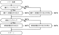
図28は、図24のステップS12にて実行されるエラー処理の詳細を示すフローチャートである。このエラー処理において、CPU113は、払出制御基板15からの払出エラー信号に基づき設定されるフラグをチェックすることにより、払出エラーを演出制御基板12側で報知させるための処理を行う。
FIG. 28 is a flowchart showing details of the error processing executed in step S12 of FIG. In this error processing, the
まず、CPU113は、図28に示すように、フラグメモリ213に設けられている満タン状態フラグがオフ状態からオン状態にセットされたか否かを判別する(ステップS111)。満タン状態フラグがオン状態にセットされた場合には(ステップS111;Yes)、満タン報知コマンドに関するコマンド送信テーブルをセットする(ステップS112)。そして、CPU113は、コマンドセット処理サブルーチンをコールしてコマンドセット処理を実行する(ステップS113)。
First, as shown in FIG. 28, the
一方、満タン状態フラグがオン状態にセットされない場合には(ステップS111;No)、CPU113は、ステップS112及びステップS113の処理をスキップする。
On the other hand, when the full state flag is not set to the on state (step S111; No), the
続いて、CPU113は、満タン状態フラグがオン状態からオフ状態にリセットされたか否かを判別する(ステップS114)。満タン状態フラグがオフ状態にリセットされた場合には(ステップS114;Yes)、満タン報知解除コマンドに関するコマンド送信テーブルをセットする(ステップS115)。そして、CPU113は、コマンドセット処理サブルーチンをコールしてコマンドセット処理を実行する(ステップS116)。
一方、満タン状態フラグがオフ状態にリセットされない場合には(ステップS114;No)、CPU113は、ステップS115及びステップS116の処理をスキップする。
Subsequently, the
On the other hand, when the full state flag is not reset to the off state (step S114; No), the
続いて、CPU113は、フラグメモリ213に設けられている球切状態フラグがオフ状態からオン状態にセットされたか否かを判別する(ステップS117)。球切状態フラグがオン状態にセットされた場合には(ステップS117;Yes)、球切報知コマンドに関するコマンド送信テーブルをセットする(ステップS118)。そして、CPU113は、コマンドセット処理サブルーチンをコールしてコマンドセット処理を実行する(ステップS119)。
Subsequently, the
一方、球切状態フラグがオン状態にセットされない場合には(ステップS117;No)、CPU113は、ステップS118及びステップS119の処理をスキップする。
On the other hand, when the ball-out state flag is not set to the on state (step S117; No), the
続いて、CPU113は、球切状態フラグがオン状態からオフ状態にリセットされたか否かを判別する(ステップS120)。球切状態フラグがオフ状態にリセットされた場合には(ステップS120;Yes)、球切報知解除コマンドに関するコマンド送信テーブルをセットする(ステップS121)。そして、CPU113は、コマンドセット処理サブルーチンをコールしてコマンドセット処理を実行し(ステップS122)、このエラー処理を終了する。
一方、満タン状態フラグがオフ状態にリセットされない場合には(ステップS120;No)、CPU113は、ステップS121及びステップS122の処理をスキップして、そのままエラー処理を終了する。
Subsequently, the
On the other hand, when the full state flag is not reset to the off state (step S120; No), the
図29は、ステップS113、S116、S119及びS122にて実行されるコマンドセット処理の詳細を示すフローチャートである。コマンドセット処理において、CPU113は、図29に示すように、まず、コマンド送信テーブルのアドレスをスタック等に退避した後、ポインタが指すコマンド送信テーブルのINTデータを引数1にロードする(ステップS231)。この引数1は、後述するコマンド送信処理に対する入力情報となるものである。
FIG. 29 is a flowchart showing details of the command set process executed in steps S113, S116, S119, and S122. In the command set process, as shown in FIG. 29, the
次に、CPU113は、コマンド送信テーブルを指すアドレスを1加算する(ステップS232)。これにより、コマンド送信テーブルが指すアドレスは、コマンドデータ1(MODEデータ)のアドレスと一致する。続いて、CPU113は、コマンドデータ1(MODEデータ)を読み出して引数2に設定する(ステップS233)。この引数2も、後述するコマンド送信処理に対する入力情報となるものである。
Next, the
そして、CPU113は、コマンド送信処理サブルーチンをコールしてコマンド送信処理を実行する(ステップS234)。
Then, the
図30は、コマンド送信処理の詳細を示すフローチャートである。コマンド送信処理において、CPU113は、まず、引数1に設定されているINTデータを比較値として決められているワークエリアに設定すると共に(ステップS301)、送信回数「2」を処理数として決められているワークエリアに設定する(ステップS302)。次に、CPU113は、出力ポート1のアドレスをI/Oアドレスにセットする(ステップS303)。
FIG. 30 is a flowchart showing details of the command transmission process. In the command transmission process, the
続いて、CPU113は、比較値を1ビット右にシフトするシフト処理を実行する(ステップS304)。そして、CPU113は、キャリーフラグをチェックして、その値が「0」であるか「1」であるかを判別する(ステップS305)。この場合にキャリーフラグの値が「1」であるということは、INTデータにおける最も右側のビットが「1」であることを意味する。この実施の形態において、払出制御コマンドの送出が指示されている場合には、1回目のシフト処理にてキャリーフラグの値が「1」になる。
Subsequently, the
キャリーフラグの値が「1」であると判別された場合には(ステップS305;No)、引数2に設定されているデータをI/Oアドレスとして設定されているアドレスに出力する(ステップS306)。
If it is determined that the value of the carry flag is “1” (step S305; No), the data set in the
なお、1回目のシフト処理では、出力ポート1のアドレスがI/Oアドレスに設定されるため、出力ポート1には、払出制御コマンドのMODEデータが出力される。
In the first shift process, since the
一方、キャリーフラグの値が「0」であると判別された場合には(ステップS305;Yes)、ステップS306の処理をスキップする。 On the other hand, if it is determined that the carry flag value is “0” (step S305; Yes), the process of step S306 is skipped.
続いて、CPU113は、I/Oアドレスを1加算すると共に(ステップS307)、処理数を1減算する(ステップS308)。これにより、I/Oアドレスには、出力ポート2のアドレスが設定される。そして、CPU113は、処理数が「0」であるか否かを判別し(ステップS309)、処理数が「0」でないと判別した場合には(ステップS309;No)、ステップS304の処理に戻り、再度シフト処理を実行する。
Subsequently, the
CPU113は、2回目のシフト処理にてINTデータにおけるビット1の値を押し出し、さらに、ステップS305の処理にてキャリーフラグの値が「0」であるか「1」であるかを判別することにより、演出制御コマンドの送出が指示されているか否かを判別する。
エラー処理(図28)のステップS113、S116、S119及びS122にて実行されるコマンドセット処理内におけるコマンド送信処理では、演出制御コマンドである満タン報知コマンド、満タン報知解除コマンド、球切報知コマンド、球切報知解除コマンドの送出が指示されているため、2回目のシフト処理後のステップS305の処理にてキャリーフラグの値が「1」であると判別され、ステップS306の処理に進む。そして、ステップS306の処理において、引数2に設定されている演出制御コマンドのMODEデータが、この時点でI/Oアドレスとして設定されている出力ポート2に出力される。
The
In the command transmission process in the command set process executed in steps S113, S116, S119, and S122 of the error process (FIG. 28), a full tank notification command, a full tank notification release command, and a ball cut notification command that are production control commands. Since the sending of the ball-cutting notification release command is instructed, it is determined that the value of the carry flag is “1” in the process of step S305 after the second shift process, and the process proceeds to step S306. In the process of step S306, the MODE data of the effect control command set in the
その後、ステップS309の処理にて処理数が「0」であると判別した場合には(ステップS309;Yes)、シフト処理開始前のINTデータが格納されている引数1の内容を読み出し(ステップS310)、読み出したデータを出力ポート0に出力する(ステップS311)。これにより、出力ポート0に出力されるINT信号は、ハイレベルになる。
Thereafter, when it is determined in step S309 that the number of processes is “0” (step S309; Yes), the contents of
続いて、CPU113は、ウェイトカウンタに所定値を設定し(ステップS312)、ウェイトカウンタの値が0になるまで、その値を1ずつ減算して行く(ステップS313、ステップS314;No)。そして、ウェイトカウンタの値が0になると(ステップS314;Yes)、クリアデータ(00)を設定し(ステップS315)、設定したクリアデータを出力ポート0に出力する(ステップS316)。これにより、出力ポート0に出力されるINT信号は、ローレベルになる。
Subsequently, the
その後、CPU113は、ウェイトカウンタに所定値を再度設定し(ステップS317)、ウェイトカウンタの値が0になるまで、その値を1ずつ減算して行く(ステップS318、ステップS319;No)。そして、ウェイトカウンタの値が0になると(ステップS319;Yes)、CPU113は、コマンド送信処理を終了する。
Thereafter, the
ステップS234のコマンド送信処理により、出力ポート2からは、演出制御コマンドのMODEデータが演出制御基板12に対して送出される。
Through the command transmission process of step S234, MODE data of the effect control command is sent from the
その後、CPU113は、コマンド送信テーブルが指すアドレスを1加算する(図29のステップS235)。これにより、コマンド送信テーブルが指すアドレスは、コマンドデータ2(EXTデータ)のアドレスと一致する。続いて、CPU113は、コマンドデータ2(EXTデータ)を読み出して引数2に設定する(ステップS236)。
Thereafter, the
そして、CPU113は、コマンドデータ2のビット7(ワークエリア参照ビット)の値が「0」であるか「1」であるかを判別する(ステップS237)。ビット7の値が「1」であると判別した場合には(ステップS237;No)、送信バッファの内容を引数2にロードする(ステップS238)。
Then, the
一方、ビット7の値が「0」であると判別した場合には(ステップS237;Yes)、ステップS238の処理をスキップする。これにより、引数2には、EXTデータが設定される。
On the other hand, when it is determined that the value of
そして、CPU113は、コマンド送信処理サブルーチンをコールしてコマンド送信処理を実行する(ステップS239)。ステップS239のコマンド送信処理により、出力ポート2からは、演出制御コマンドのEXTデータが演出制御基板12に対して送出される。
Then, the
図31及び図32は、図24のステップS20にて実行される賞球処理の詳細を示すフローチャートである。この賞球処理において、CPU113は、図31に示すように、まず、図9に示すスイッチオン判定値テーブルのオフセットとして「0」を設定し(ステップS131)、図8に示すスイッチタイマのアドレスのオフセットとして「0」を設定する(ステップS132)。スイッチオン判定値テーブルのオフセット「0」は、入賞口スイッチオン判定値「2」を使用することを意味する。また、スイッチタイマのアドレスのオフセット「0」は、入賞口スイッチ25aに対応したスイッチタイマが指定されることを意味する。また、繰返数として「4」をセットする(ステップS133)。
31 and 32 are flowcharts showing details of the prize ball processing executed in step S20 of FIG. In this prize ball processing, as shown in FIG. 31, the
そして、CPU113は、スイッチオンチェック処理サブルーチンをコールしてスイッチオンチェック処理を実行する(ステップS134)。ステップS134のスイッチオンチェック処理においては、入賞口スイッチ25aに対応するスイッチタイマの値がスイッチオン判定値「2」に一致していれば、フラグメモリ213に設けられたスイッチオンフラグがオンにセットされる。
Then, the
CPU113は、このスイッチオンフラグをチェックして、入賞口スイッチ25aがオンしているか否かを判別する(ステップS135)。入賞口スイッチ25aがオンしていると判別した場合(ステップS135;Yes)、CPU113は、払い出すべき賞球個数として「10」を図10(c)に示すリングバッファに設定する(ステップS136)。なお、CPU113は、リングバッファにデータを書き込む毎に、書込ポインタをインクリメントして行く。そして、リングバッファの最後の領域までデータを書き込んだ場合、CPU113は、書込ポインタをリングバッファの最初の領域を指すように更新する。
The
一方、入賞口スイッチ25aがオンしていないと判別した場合(ステップS135;No)、CPU113は、ステップS136の処理をスキップする。
On the other hand, when it is determined that the winning opening switch 25a is not turned on (step S135; No), the
続いて、CPU113は、繰返数を1減算し(ステップS137)、繰返数が「0」になったか否かを判別する(ステップS138)。繰返数が「0」になっていないと判別した場合(ステップS138;No)、CPU113は、スイッチタイマのアドレスのオフセットを1加算し(ステップS139)、ステップS134の処理に戻る。
Subsequently, the
一方、繰返数が「0」になったと判別した場合(ステップS138;Yes)、CPU113は、ステップS140の処理へと進む。
On the other hand, when it is determined that the number of repetitions has become “0” (step S138; Yes), the
このように、CPU113は、処理数が「0」になるまで、ステップS134〜S139の処理を繰り返し実行することにより、入賞口スイッチ25a〜25dがオンしているか否かを順次判別することができる。そして、入賞口スイッチ25a〜25dがオンしていると判別される場合、リングバッファには、払い出すべき賞球個数として「10」が設定されて行く。
As described above, the
続いて、CPU113は、スイッチオン判定値テーブルのオフセットとして「2」を設定し(ステップS140)、スイッチタイマのアドレスのオフセットとして「5」を設定する(ステップS141)。スイッチオン判定値テーブルのオフセット「2」は、始動口スイッチオン判定値「2」を使用することを意味する。また、スイッチタイマのアドレスのオフセット「5」は、始動口スイッチ22に対応したスイッチタイマが指定されることを意味する。
Subsequently, the
そして、CPU113は、スイッチオンチェック処理サブルーチンをコールしてスイッチオンチェック処理を実行する(ステップS142)。ステップS142のスイッチオンチェック処理においては、始動口スイッチ22に対応するスイッチタイマの値がスイッチオン判定値「2」に一致していれば、フラグメモリ213に設けられたスイッチオンフラグがオンにセットされる。
Then, the
CPU113は、このスイッチオンフラグをチェックして、始動口スイッチ22がオンしているか否かを判別する(ステップS143)。始動口スイッチ22がオンしていると判別した場合(ステップS143;Yes)、CPU113は、払い出すべき賞球個数として「6」をリングバッファに設定する(ステップS144)。
The
一方、始動口スイッチ22がオンしていないと判別した場合(ステップS143;No)、CPU113は、ステップS144の処理をスキップする。
On the other hand, when it is determined that the
続いて、CPU113は、スイッチオン判定値テーブルのオフセットとして「3」を設定し(ステップS145)、スイッチタイマのアドレスのオフセットとして「6」を設定する(ステップS146)。スイッチオン判定値テーブルのオフセット「3」は、カウントスイッチオン判定値「2」を使用することを意味する。また、スイッチタイマのアドレスのオフセット「6」は、カウントスイッチ24に対応したスイッチタイマが指定されることを意味する。
Subsequently, the
そして、CPU113は、スイッチオンチェック処理サブルーチンをコールしてスイッチオンチェック処理を実行する(ステップS147)。ステップS147のスイッチオンチェック処理においては、カウントスイッチ24に対応するスイッチタイマの値がスイッチオン判定値「2」に一致していれば、フラグメモリ213に設けられたスイッチオンフラグがオンにセットされる。
Then, the
CPU113は、このスイッチオンフラグをチェックして、カウントスイッチ24がオンしているか否かを判別する(ステップS148)。カウントスイッチ24がオンしていると判別した場合(ステップS148;Yes)、CPU113は、払い出すべき賞球個数として「15」をリングバッファに設定する(ステップS149)。
The
一方、カウントスイッチ24がオンしていないと判別した場合(ステップS148;No)、CPU113は、ステップS149の処理をスキップする。
On the other hand, when it is determined that the count switch 24 is not turned on (step S148; No), the
そして、CPU113は、リングバッファにデータが存在するか否かを判別する(図32のステップS150)。リングバッファにデータが存在する場合には(ステップS150;Yes)、読出ポインタが指すリングバッファの内容を送信バッファにセットすると共に(ステップS151)、読出ポインタの値をリングバッファの次の領域を指すように更新し(ステップS152)、賞球個数に関するコマンド送信テーブルをセットする(ステップS153)。
Then, the
そして、CPU113は、コマンドセット処理サブルーチンをコールして図29に示したコマンドセット処理を実行する(ステップS154)。ステップS154のコマンドセット処理においては、賞球個数に関する払出制御コマンドが格納されているコマンド送信テーブルの先頭アドレスがコマンド送信テーブルのアドレスとして設定される。これにより、主基板11からは、賞球個数に関する払出制御コマンドが払出制御基板15に対して送出される。例えば、ステップS148の処理においてカウントスイッチ24がオンしていると判別されて、ステップS149の処理においてリングバッファに「15」がセットされた場合には、このコマンドセット処理において、15個の賞球個数を指定する払出制御コマンドF00F(h)が払出制御基板15に送出される。
Then, the
ステップS150において、リングバッファにデータが存在しない場合には(ステップS150;No)、CPU113は、ステップS151〜S154の処理をスキップして、この賞球処理を終了する。
In step S150, when there is no data in the ring buffer (step S150; No), the
図33は、ステップS134、S142及びS147にて実行されるスイッチオンチェック処理の詳細を示すフローチャートである。スイッチオンチェック処理において、CPU113は、図33に示すように、まず、スイッチオン判定値テーブルの先頭アドレスをセットする(ステップS241)。そして、CPU113は、このアドレスにオフセットを加算し(ステップS242)、加算後のアドレスからスイッチオン判定値をロードする(ステップS243)。例えば、図31のステップS142のスイッチオンチェック処理の場合であれば、ステップS242において、図31のステップS140でセットされたオフセット「2」がスイッチオン判定値テーブルのアドレスに加算される。その結果、ステップS243において、図9に示す始動口スイッチオン判定値「2」がロードされる。
FIG. 33 is a flowchart showing details of the switch-on check process executed in steps S134, S142, and S147. In the switch-on check process, as shown in FIG. 33, the
続いて、CPU113は、スイッチタイマの先頭アドレスを設定し(ステップS244)、そのアドレスにオフセットを加算し(ステップS245)、加算後のアドレスからスイッチタイマの値をロードする(ステップS246)。例えば、図31のステップS142のスイッチオンチェック処理の場合であれば、ステップS245において、図31のステップS141でセットされたオフセット「5」がスイッチタイマのアドレスに加算される。その結果、ステップS246において、図8に示す始動口スイッチ用のスイッチタイマの値がロードされる。
Subsequently, the
そして、CPU113は、ロードしたスイッチタイマの値とスイッチオン判定値とを比較し(ステップS247)、スイッチタイマの値がスイッチオン判定値と一致した場合には(ステップS247;Yes)、フラグメモリ213に設けられたスイッチオンフラグをオンにセットする(ステップS248)。一方、スイッチタイマの値がスイッチオン判定値と一致していない場合には(ステップS247;No)、ステップS248の処理をスキップして、そのままスイッチオンチェック処理を終了する。
例えば、図31のステップS142のスイッチオンチェック処理の場合であれば、ステップS247において、始動口スイッチ用のスイッチタイマの値が始動口スイッチオン判定値「2」であるか否かが判別される。そして、「2」である場合に、ステップS248において、始動口スイッチ22に対応するスイッチオンフラグがオンにセットされる。
Then, the
For example, in the case of the switch-on check process in step S142 of FIG. 31, it is determined in step S247 whether the value of the switch timer for the start port switch is the start port switch-on determination value “2”. . If it is “2”, the switch-on flag corresponding to the
次に、払出制御基板15における動作を説明する。図34は、払出制御基板15に搭載された払出制御用のCPU153が実行する払出制御メイン処理を示すフローチャートである。払出制御メイン処理を開始すると、CPU153は、まず、図34に示すように、所定の初期化処理を実行することにより、RAM152のクリアや各種初期値の設定、また払出制御の起動間隔を決めるための2ミリ秒タイマの初期設定等を行う(ステップS31)。
Next, the operation in the
その後、CPU153は、フラグメモリ258に設けられたタイマ割込フラグを監視し(ステップS32)、タイマ割込フラグがセットされるまでループ処理を実行する(ステップS32;No)。この実施の形態では、CPU153にて2ミリ秒ごとにタイマ割込みが発生し、このタイマ割込みが発生すると、所定のタイマ割込処理を実行することにより、フラグメモリ258に設けられたタイマ割込フラグがセットされる。
Thereafter, the CPU 153 monitors a timer interrupt flag provided in the flag memory 258 (step S32), and executes a loop process until the timer interrupt flag is set (step S32; No). In this embodiment, a timer interrupt occurs every 2 milliseconds in the CPU 153, and when this timer interrupt occurs, a predetermined timer interrupt process is executed, thereby a timer interrupt flag provided in the
CPU153では、2ミリ秒ごとに発生するタイマ割込みとは別に主基板11からの払出制御コマンドを受信するための割込みが発生する。この割込みは、主基板11からの払出制御INT信号がオン状態となることにより発生する割込みである。払出制御INT信号がオン状態となることによる割込みが発生すると、CPU153は、図35に示すコマンド受信割込処理を実行する。
The CPU 153 generates an interrupt for receiving a payout control command from the
このコマンド受信割込処理において、CPU153は、図35に示すように、まず、各レジスタの値をスタックに退避した後、I/Oポート154のうちで払出制御信号CD0〜CD7の入力に割り当てられている入力ポートから、払出制御コマンドに対応するデータを読み込む(ステップS41)。そして、2バイト構成の払出制御コマンドのうちの1バイト目であるか否かを判別する(ステップS42)。
In this command reception interrupt process, as shown in FIG. 35, the CPU 153 first saves the value of each register to the stack and then assigns it to the input of the payout control signals CD0 to CD7 in the I /
ここで、払出制御コマンドの1バイト目(MODE)と2バイト目(EXT)とは、受信側で直ちに区別可能に構成されている。すなわち、先頭ビットによって、MODEとしてのデータを受信したのかEXTとしてのデータを受信したのかを、受信側において直ちに検出できる。受信したコマンドの先頭ビットが「1」である場合には、2バイト構成である払出制御コマンドのうちの有効な1バイト目(MODEデータ)を受信したと判別される。 Here, the first byte (MODE) and the second byte (EXT) of the payout control command are configured to be immediately distinguishable on the receiving side. In other words, the reception side can immediately detect whether the data as MODE or the data as EXT has been received by the first bit. When the first bit of the received command is “1”, it is determined that the valid first byte (MODE data) of the payout control command having a 2-byte configuration has been received.
ステップS42にて1バイト目のMODEデータであると判別したときには(ステップS42;Yes)、受信コマンドバッファメモリ251にて、コマンド受信個数カウンタにより指定される受信コマンドバッファに、受信したコマンドを格納し(ステップS43)、その後、ステップS50の処理へと進む。一方、払出制御コマンドの1バイト目でなければ(ステップS42;No)、1バイト目のMODEデータを既に受信したか否かを判別する(ステップS44)。1バイト目のMODEデータを既に受信したか否かは、受信コマンドバッファに格納されているコマンドデータを確認することにより、判別することができる。
When it is determined in step S42 that the MODE data is the first byte (step S42; Yes), the received command is stored in the reception command buffer specified by the command reception number counter in the reception
1バイト目を既に受信している場合には(ステップS44;Yes)、2バイト構成の払出制御コマンドのうちの2バイト目であるか否かを判別する(ステップS45)。このステップS45においては、今回受信した1バイトのうちの先頭ビットが「0」であるか否かを判別し、先頭ビットが「0」であれば、有効な2バイト目(EXTデータ)を受信したと判別する。ステップS45にて、2バイト目のEXTデータであると判別したときは(ステップS45;Yes)、コマンド受信個数カウンタにより指定される次の受信コマンドバッファに、受信したコマンドを格納する(ステップS46)。 If the first byte has already been received (step S44; Yes), it is determined whether or not it is the second byte of the 2-byte payout control command (step S45). In this step S45, it is determined whether or not the first bit of the one byte received this time is “0”. If the first bit is “0”, a valid second byte (EXT data) is received. It is determined that If it is determined in step S45 that the EXT data is the second byte (step S45; Yes), the received command is stored in the next reception command buffer specified by the command reception number counter (step S46). .
なお、ステップS44の処理にて払出制御コマンドの1バイト目を受信していないと判別した場合や(ステップS44;No)、ステップS45の処理にて2バイト目のEXTデータでないと判別した場合には(ステップS45;No)、ステップS50の処理へと進む。 If it is determined in step S44 that the first byte of the payout control command has not been received (step S44; No), or if it is determined in step S45 that it is not the second byte of EXT data. (Step S45; No), the process proceeds to Step S50.
ステップS46の処理にて2バイト目のコマンドデータを格納すると、コマンド受信個数カウンタの値を2加算し(ステップS47)、その値が12以上であるか否かを判別する(ステップS48)。12以上であれば(ステップS48;Yes)、コマンド受信個数カウンタをクリアして、その値を0に戻す(ステップS49)。一方、12未満のときには(ステップS48;No)、ステップS49の処理をスキップする。そして、CPU153は、退避したレジスタを復帰した後、割込許可に設定する(ステップS50)。こうしてコマンド受信割込処理により、主基板11から送られた払出制御コマンドが受信コマンドバッファメモリ251に設けられた受信コマンドバッファに格納される。
When command data of the second byte is stored in the process of step S46, the value of the command reception number counter is incremented by 2 (step S47), and it is determined whether or not the value is 12 or more (step S48). If it is 12 or more (step S48; Yes), the command reception number counter is cleared and the value is returned to 0 (step S49). On the other hand, when it is less than 12 (step S48; No), the process of step S49 is skipped. Then, after restoring the saved register, the CPU 153 sets the interrupt permission (step S50). In this way, the payout control command sent from the
こうして受信コマンドバッファに主基板11から送信された払出制御コマンドが格納される一方で、図34のステップS32の処理にてタイマ割込みの発生が確認される。タイマ割込みの発生が確認されると(ステップS32;Yes)、CPU153は、フラグメモリ258に設けられたタイマ割込フラグをクリアしてオフ状態とした後に、ステップS51〜S58の払出制御割込処理を開始する。この払出制御割込処理において、CPU153は、まず、所定のスイッチ処理を実行することにより、払出制御基板15に入力される各種スイッチ(払出モータ位置センサ71、払出カウントスイッチ72、満タンスイッチ26、球切スイッチ27等)からの検出信号を取り込み、取り込んだ検出信号の状態を判別する(ステップS51)。
In this way, the payout control command transmitted from the
次に、CPU153は、コマンド解析処理を実行して、解析結果に応じた処理を実行する(ステップS52)。さらに、所定のプリペイドカードユニット制御処理を実行する(ステップS53)。 Next, the CPU 153 executes a command analysis process, and executes a process according to the analysis result (step S52). Further, a predetermined prepaid card unit control process is executed (step S53).
この後、CPU153は、球貸要求に応じて貸球を払い出す球貸制御処理を行う(ステップS54)。さらに、賞球総数カウンタに格納された個数の賞球を払い出す賞球制御処理を実行する(ステップS55)。そして、払出装置50の払出モータ51に対して駆動信号を出力し、払出モータ51を回転させる払出モータ制御処理を実行する(ステップS56)。
Thereafter, the CPU 153 performs a ball lending control process for paying out a ball in response to a ball lending request (step S54). Further, a prize ball control process for paying out the number of prize balls stored in the prize ball total counter is executed (step S55). And a drive signal is output with respect to the
続いて、CPU153は、所定のエラー処理を実行することにより、遊技球の払い出しに関する異常診断を行い、その診断結果に応じて必要ならば所定のエラー表示用LED等により警告を発生可能とし、また主基板11に対して払い出しができない状態であることを示す払出エラー信号を出力可能とする(ステップS57)。そして、所定の出力処理を実行することにより、遊技機外部に球貸個数信号を出力する(ステップS58)。
Subsequently, the CPU 153 performs a predetermined error process to perform abnormality diagnosis related to the payout of the game ball, and according to the diagnosis result, if necessary, a warning can be generated by a predetermined error display LED, etc. A payout error signal indicating that the payout cannot be performed on the
図36は、ステップS51にて実行されるスイッチ処理の詳細を示すフローチャートである。このスイッチ処理において、CPU153は、図36に示すように、まず、入力ポート2に入力されているデータを受信する(ステップS501)。次に、CPU153は、処理数として「4」を設定し(ステップS502)、払出モータ位置センサ71のスイッチタイマのアドレス「0」をポインタにセットする(ステップS503)。この後、CPU153は、スイッチチェック処理サブルーチンをコールしてスイッチチェック処理を実行する(ステップS504)。
FIG. 36 is a flowchart showing details of the switch processing executed in step S51. In this switch processing, the CPU 153 first receives data input to the
このスイッチチェック処理は、主基板11の遊技制御用マイクロコンピュータ110が実行する図26に示したスイッチチェック処理と同じであるので、その説明を省略する。
Since this switch check process is the same as the switch check process shown in FIG. 26 executed by the
ステップS504のスイッチチェック処理において、CPU153は、払出モータ位置センサ71、払出カウントスイッチ72、満タンスイッチ26及び球切スイッチ27について、その検出信号がオン状態にあるか否かを順次判別し、検出信号がオン状態にあるスイッチに対応するスイッチタイマ値を1加算する。
In the switch check process in step S504, the CPU 153 sequentially determines whether or not the detection signals of the payout
続いて、CPU153は、カウント処理サブルーチンをコールしてカウント処理を実行する(ステップS505)。このカウント処理において、CPU153は、払出モータ位置センサ71及び払出カウントスイッチ72のスイッチタイマの値に基づいて、払出動作量カウンタ254、賞球総数カウンタ255及び貸球総数カウンタ256の値の減算処理を行う。
Subsequently, the CPU 153 calls a count processing subroutine to execute count processing (step S505). In this counting process, the CPU 153 performs a subtraction process for the values of the payout
さらに、CPU153は、フラグ処理サブルーチンをコールしてフラグ処理を実行し(ステップS506)、このスイッチ処理を終了する。このフラグ処理において、CPU153は、満タンスイッチ26及び球切スイッチ27のスイッチタイマの値に基づいて、フラグメモリ258に設けられている満タンフラグ及び球切フラグの設定を行う。
Further, the CPU 153 calls a flag processing subroutine to execute flag processing (step S506), and ends this switch processing. In this flag processing, the CPU 153 sets the full tank flag and the ball cut flag provided in the
図37は、ステップS505にて実行されるカウント処理の詳細を示すフローチャートである。このカウント処理において、CPU153は、図37に示すように、まず、図16に示すスイッチオン判定値テーブルのオフセットとして「0」を設定し(ステップS601)、図15に示すスイッチタイマのアドレスのオフセットとして「0」を設定する(ステップS602)。スイッチオン判定値テーブルのオフセット「0」は、払出モータ位置センサスイッチオン判定値「2」を使用することを意味する。また、スイッチタイマのアドレスのオフセット「0」は、払出モータ位置センサ71に対応したスイッチタイマが指定されることを意味する。
FIG. 37 is a flowchart showing details of the count process executed in step S505. In this counting process, as shown in FIG. 37, the CPU 153 first sets “0” as the offset of the switch-on determination value table shown in FIG. 16 (step S601), and the offset of the address of the switch timer shown in FIG. "0" is set as (step S602). The offset “0” in the switch-on determination value table means that the payout motor position sensor switch-on determination value “2” is used. Further, the offset “0” of the switch timer address means that the switch timer corresponding to the payout
そして、CPU153は、スイッチオンチェック処理サブルーチンをコールしてスイッチオンチェック処理を実行する(ステップS603)。このステップS603及び以下に示すステップS608のスイッチオンチェック処理は、主基板11の遊技制御用マイクロコンピュータ110が実行する図33に示したスイッチオンチェック処理と同じであるので、その説明を省略する。
ステップS603のスイッチオンチェック処理においては、払出モータ位置センサ71に対応するスイッチタイマの値がスイッチオン判定値「2」に一致していれば、フラグメモリ258に設けられたスイッチオンフラグがオンにセットされる。
Then, the CPU 153 calls a switch-on check processing subroutine to execute switch-on check processing (step S603). Since the switch-on check process of step S603 and step S608 shown below is the same as the switch-on check process shown in FIG. 33 executed by the
In the switch-on check process in step S603, if the value of the switch timer corresponding to the payout
CPU153は、このスイッチオンフラグをチェックして、払出モータ位置センサ71がオンしているか否かを判別する(ステップS604)。払出モータ位置センサ71がオンしていると判別した場合(ステップS604;Yes)、CPU153は、払出モータ51による1個の遊技球の払出動作が完了したものと判別して、払出動作量カウンタ254の値を1減算する(ステップS605)。
The CPU 153 checks the switch-on flag to determine whether or not the payout
一方、払出モータ位置センサ71がオンしていないと判別した場合には(ステップS604;No)、CPU153は、ステップS605の処理をスキップする。
On the other hand, if it is determined that the dispensing
次に、CPU153は、スイッチオン判定値テーブルのオフセットとして「1」を設定し(ステップS606)、スイッチタイマのアドレスのオフセットとして「1」を設定する(ステップS607)。スイッチオン判定値テーブルのオフセット「1」は、払出カウントスイッチオン判定値「2」を使用することを意味する。また、スイッチタイマのアドレスのオフセット「1」は、払出カウントスイッチ72に対応したスイッチタイマが指定されることを意味する。
Next, the CPU 153 sets “1” as the offset of the switch-on determination value table (step S606), and sets “1” as the offset of the switch timer address (step S607). The offset “1” in the switch-on determination value table means that the payout count switch-on determination value “2” is used. Further, the offset “1” of the address of the switch timer means that a switch timer corresponding to the
そして、CPU153は、スイッチオンチェック処理サブルーチンをコールしてスイッチオンチェック処理を実行する(ステップS608)。ステップS608のスイッチオンチェック処理においては、払出カウントスイッチ72に対応するスイッチタイマの値がスイッチオン判定値「2」に一致していれば、フラグメモリ258に設けられたスイッチオンフラグがオンにセットされる。
Then, the CPU 153 calls a switch on check processing subroutine to execute the switch on check processing (step S608). In the switch-on check process in step S608, if the value of the switch timer corresponding to the
CPU153は、このスイッチオンフラグをチェックして、払出カウントスイッチ72がオンしているか否かを判別する(ステップS609)。払出カウントスイッチ72がオンしていると判別した場合(ステップS609;Yes)、CPU153は、払出装置50から1個の遊技球が払い出されたものと判別すると共に、この遊技球が賞球として払い出されたものであるか遊技者に貸し出すために払い出されたものであるかを、フラグメモリ258に設けられている賞球払出中フラグ及び貸球払出中フラグをチェックすることにより、判別する(ステップS610)。
The CPU 153 checks the switch-on flag to determine whether or not the
ステップS610の処理にて、賞球払出中フラグがオン状態であることにより払出装置50から遊技球が賞球として払い出されたものと判別した場合(ステップS610;Yes)、CPU153は、賞球総数カウンタ255の値を1減算して(ステップS611)、カウント処理を終了する。
When it is determined in the process of step S610 that the game ball has been paid out as a prize ball from the
一方、ステップS610の処理にて、貸球払出中フラグがオン状態であることにより払出装置50から遊技球が遊技者に貸し出すために払い出されたものと判別した場合(ステップS610;No)、CPU153は、貸球総数カウンタ256の値を1減算して(ステップS612)、カウント処理を終了する。
On the other hand, when it is determined in the process of step S610 that the game ball has been paid out for lending to the player from the
また、ステップS609の処理にて払出カウントスイッチ72がオンしていないと判別した場合には(ステップS609;No)、CPU153は、ステップS610、S611及びS612の処理をスキップして、カウント処理を終了する。
If it is determined in step S609 that the
図38は、図36のステップS506にて実行されるフラグ処理の詳細を示すフローチャートである。このフラグ処理において、CPU153は、図38に示すように、まず、図16に示すスイッチオン判定値テーブルのオフセットとして「2」を設定し(ステップS621)、図15に示すスイッチタイマのアドレスのオフセットとして「2」を設定する(ステップS622)。スイッチオン判定値テーブルのオフセット「2」は、満タンスイッチオン判定値「50」を使用することを意味する。また、スイッチタイマのアドレスのオフセット「2」は、満タンスイッチ26に対応したスイッチタイマが指定されることを意味する。
FIG. 38 is a flowchart showing details of the flag process executed in step S506 of FIG. In this flag processing, as shown in FIG. 38, the CPU 153 first sets “2” as the offset of the switch-on determination value table shown in FIG. 16 (step S621), and the offset of the switch timer address shown in FIG. Is set to “2” (step S622). The offset “2” in the switch-on determination value table means that the full switch-on determination value “50” is used. An offset “2” of the switch timer address means that a switch timer corresponding to the
そして、CPU153は、スイッチオンチェック処理サブルーチンをコールしてスイッチオンチェック処理を実行する(ステップS623)。このステップS623及び以下に示すステップS628のスイッチオンチェック処理は、主基板11の遊技制御用マイクロコンピュータ110が実行する図33に示したスイッチオンチェック処理と同じであるので、その説明を省略する。
ステップS623のスイッチオンチェック処理においては、満タンスイッチ26に対応するスイッチタイマの値が満タンスイッチオン判定値「50」に一致していれば、フラグメモリ258に設けられたスイッチオンフラグがオンにセットされる。
Then, the CPU 153 calls a switch-on check processing subroutine to execute switch-on check processing (step S623). Since the switch-on check process of step S623 and step S628 shown below is the same as the switch-on check process shown in FIG. 33 executed by the
In the switch-on check process in step S623, if the value of the switch timer corresponding to the full-
CPU153は、このスイッチオンフラグをチェックして、満タンスイッチ26がオンしているか否かを判別する(ステップS624)。満タンスイッチ26がオンしていると判別した場合(ステップS624;Yes)、CPU113は、フラグメモリ258に設けられた満タンフラグをオンにセットする(ステップS625)。なお、この満タンフラグは、満タンスイッチ26に対応したスイッチタイマの値が「0」になるとリセットされてオフになる。
The CPU 153 checks the switch on flag to determine whether or not the
一方、満タンスイッチ26がオンしていないと判別した場合(ステップS624;No)、CPU153は、ステップS625の処理をスキップする。
On the other hand, when it is determined that the
続いて、CPU153は、スイッチオン判定値テーブルのオフセットとして「3」を設定し(ステップS626)、スイッチタイマのアドレスのオフセットとして「3」を設定する(ステップS627)。スイッチオン判定値テーブルのオフセット「3」は、球切スイッチオン判定値「250」を使用することを意味する。また、スイッチタイマのアドレスのオフセット「3」は、球切スイッチ27に対応したスイッチタイマが指定されることを意味する。
Subsequently, the CPU 153 sets “3” as the offset of the switch-on determination value table (step S626), and sets “3” as the offset of the switch timer address (step S627). The offset “3” in the switch-on determination value table means that the ball-off switch-on determination value “250” is used. Further, the offset “3” of the address of the switch timer means that a switch timer corresponding to the ball-
そして、CPU153は、スイッチオンチェック処理サブルーチンをコールしてスイッチオンチェック処理を実行する(ステップS628)。ステップS628のスイッチオンチェック処理においては、球切スイッチ27に対応するスイッチタイマの値が球切スイッチオン判定値「250」に一致していれば、フラグメモリ258に設けられたスイッチオンフラグがオンにセットされる。
Then, the CPU 153 calls a switch-on check processing subroutine to execute switch-on check processing (step S628). In the switch-on check process in step S628, if the value of the switch timer corresponding to the ball-
CPU153は、このスイッチオンフラグをチェックして、球切スイッチ27がオンしているか否かを判別する(ステップS629)。球切スイッチ27がオンしていると判別した場合(ステップS629;Yes)、CPU153は、フラグメモリ258に設けられた球切フラグをオンにセットして(ステップS630)、フラグ処理を終了する。なお、この球切フラグは、球切スイッチ27に対応したスイッチタイマの値が「30」になるとリセットされてオフになる。
The CPU 153 checks the switch on flag to determine whether or not the ball cut
一方、球切スイッチ27がオンしていないと判別した場合(ステップS629;No)、CPU153は、ステップS630の処理をスキップして、フラグ処理を終了する。
On the other hand, when it is determined that the ball cut
図39は、図34のステップS52のコマンド解析処理の詳細を示すフローチャートである。このコマンド解析処理において、CPU153は、図39に示すように、まず、受信コマンドバッファメモリ251に設けられた受信コマンドバッファに、主基板11から受信した払出制御コマンドが格納されているか否かを確認する(ステップS511)。
FIG. 39 is a flowchart showing details of the command analysis processing in step S52 of FIG. In this command analysis process, as shown in FIG. 39, the CPU 153 first checks whether or not the payout control command received from the
受信コマンドバッファに受信コマンドが格納されている場合(ステップS511;Yes)、CPU153は、受信コマンドバッファから受信コマンドを読み出し、読み出した受信コマンドが賞球個数を指定する払出制御コマンドであるか否かを判別する(ステップS512)。なお、読み出したら読出ポインタの値を1加算しておく。 When the received command is stored in the received command buffer (step S511; Yes), the CPU 153 reads the received command from the received command buffer, and whether or not the read received command is a payout control command for designating the number of winning balls. Is determined (step S512). When read, the read pointer value is incremented by one.
読み出した受信コマンドが賞球個数を指定する払出制御コマンドであると判別した場合(ステップS512;Yes)、CPU153は、払出制御コマンドにより指示された賞球個数を、賞球総数カウンタ255の内容に加算する(ステップS513)。続いて、CPU153は、フラグメモリ258に設けられている賞球払出中フラグをチェックして、払出装置50が賞球の払出動作を実行しているか否かを判別する(ステップS514)。
If it is determined that the read received command is a payout control command for designating the number of winning balls (step S512; Yes), the CPU 153 uses the number of winning balls designated by the payout control command as the contents of the winning ball
払出装置50が賞球の払出動作を実行していると判別した場合(ステップS514;Yes)、CPU153は、払出制御コマンドにより指定された賞球個数を、払出中受信個数カウンタ257の内容に加算すると共に(ステップS515)、フラグメモリ258に設けられている払出中受信フラグをオンにセットする(ステップS516)。
When it is determined that the
一方、ステップS511の処理にて受信コマンドバッファに受信コマンドが格納されていないと判別した場合(ステップS511;No)、ステップS512の処理にて読み出した受信コマンドが賞球個数を指定する払出制御コマンド以外であると判別した場合(ステップS512;No)及びステップS514の処理にて払出装置50が賞球の払出動作を実行していないと判別した場合(ステップS514;No)、CPU153は、そのままコマンド解析処理を終了する。
On the other hand, when it is determined that the received command is not stored in the received command buffer in the process of step S511 (step S511; No), the payout control command in which the received command read in the process of step S512 specifies the number of prize balls If it is determined that the
図40及び図41は、図34のステップS54にて実行される球貸制御処理の詳細を示すフローチャートである。なお、この球貸制御処理において、払出装置50から連続的に払い出される貸球の個数の最大値は、貸球の一単位と同数(例えば25個)であるが、この値は任意であり、他の数であってもよい。
40 and 41 are flowcharts showing details of the ball lending control process executed in step S54 of FIG. In this ball lending control process, the maximum value of the number of balls that are continuously paid out from the
球貸制御処理が開始すると、CPU153は、図40に示すように、まず、フラグメモリ258に設けられている満タンフラグがオン状態であるか否かを判別する(ステップS521)。満タンフラグがオン状態でないと判別した場合には(ステップS521;No)、CPU153は、球切フラグがオン状態であるか否かを判別する(ステップS522)。ステップS521の処理にて満タンフラグがオン状態であると判別した場合(ステップS521;Yes)及びステップS522の処理にて球切フラグがオン状態であると判別した場合(ステップS522;Yes)には、CPU153は、払出装置50から遊技球を払い出すことができない状態であるとして、そのまま球貸制御処理を終了する。
When the ball lending control process is started, as shown in FIG. 40, the CPU 153 first determines whether or not the full tank flag provided in the
一方、ステップS521及びS522の処理にて満タンフラグも球切フラグもオン状態でないと判別した場合には(ステップS521;No,ステップS522;No)、フラグメモリ258に設けられている貸球払出中フラグをチェックして、貸球の払出が行われているか否かを判別する(ステップS523)。貸球の払出が行われていると判別した場合には(ステップS523;Yes)、ステップS530の処理へと進む。
On the other hand, when it is determined in the processes of steps S521 and S522 that neither the full flag nor the ball-out flag is on (step S521; No, step S522; No), the lending payout provided in the
一方、貸球の払出が行われていないと判別した場合には(ステップS523;No)、続いて、フラグメモリ258に設けられている賞球払出中フラグをチェックして、賞球の払出が行われているか否かを判別する(ステップS524)。賞球の払出が行われていると判別した場合には(ステップS524;Yes)、そのまま球貸制御処理を終了する。
On the other hand, when it is determined that the rental ball has not been paid out (step S523; No), the prize ball paying flag provided in the
そして、ステップS523及びS524の処理にて貸球の払出も賞球の払出も行われていないと判別した場合(ステップS523;No,ステップS524;No)、CPU153は、カードユニット70から球貸要求があったか否かを判別する(ステップS525)。球貸要求がないと判別した場合には(ステップS525;No)、そのまま球貸制御処理を終了する。
If it is determined in the processes in steps S523 and S524 that neither a rental ball is paid out nor a prize ball is paid out (step S523; No, step S524; No), the CPU 153 requests a ball rental from the
一方、球貸要求があったと判別した場合には(ステップS525;Yes)、CPU153は、フラグメモリ258に設けられている貸球払出中フラグをオンすると共に(ステップS526)、貸球総数カウンタ256及び払出動作量カウンタ254に「25」を設定する(ステップS527)。
On the other hand, if it is determined that a ball lending request has been made (step S525; Yes), the CPU 153 turns on a lending payout flag provided in the flag memory 258 (step S526), and a lending
そして、CPU153は、EXS信号をオンすると共に(ステップS528)、カードユニット70がEXS信号のオンに基づき球貸要求信号であるBRQ信号をオフ状態にした後、払出モータ51を駆動する(ステップS529)。これにより、球貸制御処理は、球貸動作前の処理から球貸中の処理へと移行する。
Then, the CPU 153 turns on the EXS signal (step S528) and drives the
球貸中の処理において、CPU153は、まず、払出球通過待ち時間中であるか否かを判別する(図41のステップS530)。この払出球通過待ち時間とは、最後の払出球が払出モータ51によって払い出されてから払出カウントスイッチ72を通過するまでの時間である。ステップS530の処理にて払出球通過待ち時間中でないと判別した場合(ステップS530;No)、CPU153は、貸球の払出を行う(ステップS531)。
In the ball lending process, the CPU 153 first determines whether or not it is during the payout ball passage waiting time (step S530 in FIG. 41). The payout ball passage waiting time is the time from when the last payout ball is paid out by the
そして、CPU153は、払出動作量カウンタ254の値が「0」になったか否かを判別する(ステップS532)。払出動作量カウンタ254の値が「0」になった場合(ステップS532;Yes)、CPU153は、25個の貸球を払い出すために必要な動作が完了したものと判別して、払出モータ51の払出動作を停止すると共に(ステップS533)、払出球通過待ち時間の設定を行い(ステップS534)、球貸制御処理を終了する。
Then, the CPU 153 determines whether or not the value of the payout
一方、ステップS532の処理にて払出動作量カウンタ254の値が「0」になっていない場合(ステップS532;No)、CPU153は、そのまま球貸制御処理を終了する。
On the other hand, when the value of the payout
ステップS530の処理にて払出球通過待ち時間中であると判別した場合(ステップS530;Yes)、CPU153は、この払出球通過待ち時間が終了したか否かを判別する(ステップS535)。払出球通過待ち時間が終了していないと判別した場合には(ステップS535;No)、そのまま球貸制御処理を終了する。 When it is determined in the process of step S530 that the payout ball passage waiting time is being reached (step S530; Yes), the CPU 153 determines whether or not the payout ball passage waiting time has ended (step S535). When it is determined that the payout ball passage waiting time has not ended (step S535; No), the ball lending control process is ended as it is.
一方、払出球通過待ち時間が終了したと判別した場合(ステップS535;Yes)、貸球総数カウンタ256の値が「0」になっているか否かを判別する(ステップS536)。貸球総数カウンタ256の値が「0」になっていない場合(ステップS536;No)、未払出の貸球があると判別して、貸球総数カウンタ256の値を払出動作量カウンタ254にセットし(ステップS537)、払出モータ51を再駆動する(ステップS538)。その後、CPU153は、ステップS530の処理へと戻る。
On the other hand, when it is determined that the payout ball passage waiting time has ended (step S535; Yes), it is determined whether or not the value of the total number of rental balls counter 256 is “0” (step S536). When the value of the total number of
一方、貸球総数カウンタ256の値が「0」になっている場合(ステップS536;Yes)、一単位の貸球が全て払い出されたものと判別して、カードユニット70に対して次の球貸要求の受付が可能になったことを示すためにEXS信号をオフにすると共に(ステップS539)、貸球払出中フラグをオフし(ステップS540)、貸球制御処理を終了する。
On the other hand, when the value of the total number of rented
図42及び図43は、図34のステップS55にて実行される賞球制御処理の詳細を示すフローチャートである。賞球制御処理が開始すると、CPU153は、図42に示すように、まず、フラグメモリ258に設けられている満タンフラグがオン状態であるか否かを判別する(ステップS551)。満タンフラグがオン状態でないと判別した場合には(ステップS551;No)、CPU153は、球切フラグがオン状態であるか否かを判別する(ステップS552)。
42 and 43 are flowcharts showing details of the prize ball control process executed in step S55 of FIG. When the winning ball control process starts, as shown in FIG. 42, the CPU 153 first determines whether or not the full tank flag provided in the
ステップS551の処理にて満タンフラグがオン状態であると判別した場合(ステップS551;Yes)及びステップS552の処理にて球切フラグがオン状態であると判別した場合(ステップS552;Yes)には、CPU153は、払出装置50から遊技球を払い出すことができない状態であるとして、そのまま賞球制御処理を終了する。
When it is determined in the process of step S551 that the full flag is on (step S551; Yes) and in the process of step S552, it is determined that the ball cut flag is on (step S552; Yes). The CPU 153 determines that the game ball cannot be paid out from the
一方、ステップS551及びS552の処理にて満タンフラグも球切フラグもオン状態でないと判別した場合には(ステップS551;No,ステップS552;No)、フラグメモリ258に設けられている貸球払出中フラグをチェックして、貸球の払出が行われているか否かを判別する(ステップS553)。貸球の払出が行われていると判別した場合には(ステップS553;Yes)、そのまま賞球制御処理を終了する。
On the other hand, when it is determined in the processes of steps S551 and S552 that neither the full flag nor the ball-off flag is in the on state (step S551; No, step S552; No), the lending payout provided in the
一方、貸球の払出が行われていないと判別した場合には(ステップS553;No)、続いて、フラグメモリ258に設けられている賞球払出中フラグをチェックして、賞球の払出が行われているか否かを判別する(ステップS554)。賞球の払出が行われていると判別した場合には(ステップS554;Yes)、ステップS559の処理へと進む。
On the other hand, when it is determined that the rental ball is not paid out (step S553; No), the prize ball payout flag provided in the
そして、ステップS553及びS554の処理にて貸球の払出も賞球の払出も行われていないと判別した場合(ステップS553;No,ステップS554;No)、CPU153は、賞球総数カウンタ255の値が「0」でないか否かを判別する(ステップS555)。賞球総数カウンタ255に格納されている賞球数が「0」である場合には(ステップS555;Yes)、そのまま賞球制御処理を終了する。
When it is determined in the processes of steps S553 and S554 that neither a rental ball nor a prize ball is paid out (step S553; No, step S554; No), the CPU 153 determines the value of the total number of winning balls counter 255. Is not "0" (step S555). When the number of prize balls stored in the prize ball
一方、賞球総数カウンタ255の値が「0」でない場合(ステップS555;No)、CPU153は、フラグメモリ258に設けられている賞球払出中フラグをオンすると共に(ステップS556)、払出動作量カウンタ254に賞球総数カウンタ255の値を設定する(ステップS557)。そして、CPU153は、払出モータ51を駆動する(ステップS558)。これにより、賞球制御処理は、賞球動作前の処理から賞球動作中の処理へと移行する。
On the other hand, when the value of the winning ball
賞球動作中の処理において、CPU153は、まず、払出球通過待ち時間中であるか否かを判別する(図43のステップS559)。ステップS559の処理にて払出球通過待ち時間中でないと判別した場合(ステップS559;No)、CPU153は、賞球の払出を行う(ステップS560)。 In the processing during the winning ball operation, the CPU 153 first determines whether or not it is during the payout ball passage waiting time (step S559 in FIG. 43). If it is determined in step S559 that the payout ball passage waiting time is not being reached (step S559; No), the CPU 153 pays out a prize ball (step S560).
そして、CPU153は、フラグメモリ258に設けられている払出中受信フラグをチェックして、賞球払出中に賞球個数を指定する払出制御コマンドを受信したか否かを判別する(ステップS561)。賞球払出中に賞球個数を指定する払出制御コマンドを受信したと判別した場合(ステップS561;Yes)、CPU153は、払出動作量カウンタ254の値に払出中受信個数カウンタ257の内容を加算する(ステップS562)。その後、CPU153は、払出中受信個数カウンタ257を0クリアすると共に(ステップS563)、払出中受信フラグをオフし(ステップS564)、賞球制御処理を終了する。
The CPU 153 checks the payout receiving flag provided in the
ステップS561の処理にて賞球払出中に賞球個数を指定する払出制御コマンドを受信していないと判別した場合(ステップS561;No)、CPU153は、払出動作量カウンタ254の値が「0」になったか否かを判別する(ステップS565)。払出動作量カウンタ254の値が「0」になった場合(ステップS565;Yes)、CPU153は、賞球を全て払い出すために必要な動作が完了したものと判別して、払出モータ51の払出動作を停止すると共に(ステップS566)、払出球通過待ち時間の設定を行い(ステップS567)、賞球制御処理を終了する。
If it is determined in step S561 that the payout control command for designating the number of prize balls is not received during the payout of the winning ball (step S561; No), the CPU 153 sets the value of the payout
一方、払出動作量カウンタ254の値が「0」になっていない場合(ステップS565;No)、CPU153は、そのまま賞球制御処理を終了する。
On the other hand, when the value of the payout
ステップS559の処理にて払出球通過待ち時間中であると判別した場合(ステップS559;Yes)、CPU153は、この払出球通過待ち時間が終了したか否かを判別する(ステップS568)。払出球通過待ち時間が終了していないと判別した場合には(ステップS568;No)、そのまま賞球制御処理を終了する。 When it is determined in the process of step S559 that the payout ball passage waiting time is being reached (step S559; Yes), the CPU 153 determines whether or not the payout ball passage waiting time has ended (step S568). When it is determined that the payout ball passage waiting time has not ended (step S568; No), the award ball control process is ended as it is.
一方、払出球通過待ち時間が終了したと判別した場合(ステップS568;Yes)、賞球総数カウンタ255の値が「0」になっているか否かを判別する(ステップS569)。賞球総数カウンタ255の値が「0」になっていない場合(ステップS569;No)、未払出の賞球があると判別して、賞球総数カウンタ255の値を払出動作量カウンタ254にセットし(ステップS570)、払出モータ51を再駆動する(ステップS571)。その後、CPU153は、ステップS559の処理へと戻る。
On the other hand, when it is determined that the payout ball passage waiting time has ended (step S568; Yes), it is determined whether or not the value of the winning ball
一方、賞球総数カウンタ255の値が「0」になっている場合(ステップS569;Yes)、賞球が全て払い出されたものと判別して、賞球払出中フラグをオフし(ステップS572)、賞球制御処理を終了する。
On the other hand, if the value of the winning ball
以上に説明した賞球制御処理においては、払出装置50から連続して払い出される遊技球の個数には、上限が設けられていなかった。しかしながら、本発明は、これに限定されず、払出装置50から連続して払い出される遊技球の個数に、所定の上限値を設けてもよい。
In the prize ball control process described above, there is no upper limit on the number of game balls that are continuously paid out from the
図44、図45及び図46は、図34のステップS55にて実行される賞球制御処理の変形例を示すフローチャートである。 44, 45 and 46 are flowcharts showing a modified example of the prize ball control process executed in step S55 of FIG.
この賞球制御処理において、払出制御基板15には、払出装置50から連続的に払い出される遊技球の上限値として、貸球の一単位の個数(例えば25個)が設定されている。この賞球制御処理が開始すると、CPU153は、まず、図44に示すように、フラグメモリ258に設けられている満タンフラグがオン状態であるか否かを判別する(ステップS641)。満タンフラグがオン状態でないと判別した場合には(ステップS641;No)、CPU153は、球切フラグがオン状態であるか否かを判別する(ステップS642)。
In this award ball control process, the number (for example, 25) of units of rented balls is set on the
ステップS641の処理にて満タンフラグがオン状態であると判別した場合(ステップS641;Yes)及びステップS642の処理にて球切フラグがオン状態であると判別した場合(ステップS642;Yes)には、CPU153は、払出装置50から遊技球を払い出すことができない状態であるとして、そのまま賞球制御処理を終了する。
When it is determined in the process of step S641 that the full flag is on (step S641; Yes) and in the process of step S642, it is determined that the ball cut flag is on (step S642; Yes). The CPU 153 determines that the game ball cannot be paid out from the
一方、ステップS641及びS642の処理にて満タンフラグも球切フラグもオン状態でないと判別した場合には(ステップS641;No,ステップS642;No)、フラグメモリ258に設けられている貸球払出中フラグをチェックして、貸球の払出が行われているか否かを判別する(ステップS643)。貸球の払出が行われていると判別した場合には(ステップS643;Yes)、そのまま賞球制御処理を終了する。
On the other hand, when it is determined in the processes of steps S641 and S642 that neither the full flag nor the ball-off flag is on (step S641; No, step S642; No), the renting out of the sphere provided in the
一方、貸球の払出が行われていないと判別した場合には(ステップS643;No)、続いて、フラグメモリ258に設けられている賞球払出中フラグをチェックして、賞球の払出が行われているか否かを判別する(ステップS644)。賞球の払出が行われていると判別した場合には(ステップS644;Yes)、ステップS651の処理へと進む。
On the other hand, when it is determined that the rental ball has not been paid out (step S643; No), the prize ball paying-in flag provided in the
そして、ステップS643及びS644の処理にて貸球の払出も賞球の払出も行われていないと判別した場合(ステップS643;No,ステップS644;No)、CPU153は、賞球総数カウンタ255の値が「0」でないか否かを判別する(ステップS645)。賞球総数カウンタ255に格納されている賞球数が「0」である場合には(ステップS645;Yes)、そのまま賞球制御処理を終了する。
When it is determined in the processes of steps S643 and S644 that neither the lending of the lent ball nor the payout of the winning ball is performed (step S643; No, step S644; No), the CPU 153 determines the value of the winning ball
一方、賞球総数カウンタ255の値が「0」でない場合(ステップS645;No)、CPU153は、フラグメモリ258に設けられている賞球払出中フラグをオンし(ステップS646)、賞球総数カウンタ255の値が「25」以上であるか否かを判別する(ステップS647)。
On the other hand, when the value of the prize ball
賞球総数カウンタ255の値が「25」以上であると判別した場合(ステップS647;Yes)、CPU153は、払出動作量カウンタ254に「25」を設定する(ステップS648)。一方、賞球総数カウンタ255の値が「25」未満であると判別した場合(ステップS647;No)、CPU153は、払出動作量カウンタ254に賞球総数カウンタ255の値を設定する(ステップS649)。そして、CPU153は、払出モータ51を駆動する(ステップS650)。これにより、賞球制御処理は、賞球動作前の処理から賞球動作中の処理へと移行する。
When it is determined that the value of the winning ball
賞球動作中の処理において、CPU153は、まず、払出球通過待ち時間中であるか否かを判別する(図45のステップS651)。ステップS651の処理にて払出球通過待ち時間中でないと判別した場合(ステップS651;No)、CPU153は、賞球の払出を行う(ステップS652)。 In the processing during the winning ball operation, the CPU 153 first determines whether or not it is during the payout ball passage waiting time (step S651 in FIG. 45). If it is determined in step S651 that the payout ball passage waiting time is not being reached (step S651; No), the CPU 153 pays out a prize ball (step S652).
そして、CPU153は、フラグメモリ258に設けられている払出中受信フラグをチェックして、賞球払出中に賞球個数を指定する払出制御コマンドを受信したか否かを判別する(ステップS653)。賞球払出中に賞球個数を指定する払出制御コマンドを受信したと判別した場合(ステップS653;Yes)、払出動作量カウンタ254の値と払出中受信個数カウンタ257の値との加算値を求める(ステップS654)。
Then, the CPU 153 checks the payout receiving flag provided in the
続いて、ステップS654で求めた加算値が「25」以上であるか否かを判別する(ステップS655)。ステップS654で求めた加算値が「25」以上であると判別した場合(ステップS655;Yes)、CPU153は、払出動作量カウンタ254の値に「25」を設定する共に(ステップS656)、ステップS654で求めた加算値から「25」を減算した値(減算値)を払出中受信個数カウンタ257に設定し(ステップS657)、賞球制御処理を終了する。 Subsequently, it is determined whether or not the added value obtained in step S654 is “25” or more (step S655). When it is determined that the added value obtained in step S654 is “25” or more (step S655; Yes), the CPU 153 sets “25” as the value of the payout operation amount counter 254 (step S656), and step S654. A value (subtraction value) obtained by subtracting “25” from the addition value obtained in the above is set in the payout received number counter 257 (step S657), and the winning ball control process is terminated.
一方、ステップS654で求めた加算値が「25」未満であると判別した場合(ステップS655;No)、CPU153は、払出動作量カウンタ254の値に払出中受信個数カウンタ257の値を加算する(ステップS658)、そして、CPU153は、払出中受信個数カウンタ257を0クリアすると共に(ステップS659)、払出中受信フラグをオフし(ステップS660)、賞球制御処理を終了する。
On the other hand, if it is determined that the added value obtained in step S654 is less than “25” (step S655; No), the CPU 153 adds the value of the payout received
ステップS653の処理にて賞球払出中に賞球個数を指定する払出制御コマンドを受信していないと判別した場合(ステップS653;No)、CPU153は、払出動作量カウンタ254の値が「0」になったか否かを判別する(ステップS661)。払出動作量カウンタ254の値が「0」になった場合(ステップS661;Yes)、CPU153は、賞球を全て払い出すために必要な動作が完了したものと判別して、払出モータ51の払出動作を停止すると共に(ステップS662)、払出球通過待ち時間の設定を行い(ステップS663)、賞球制御処理を終了する。
If it is determined in step S653 that the payout control command for designating the number of prize balls has not been received during the payout of the winning ball (step S653; No), the CPU 153 sets the value of the payout
一方、払出動作量カウンタ254の値が「0」になっていない場合(ステップS661;No)、CPU153は、そのまま賞球制御処理を終了する。
On the other hand, when the value of the payout
ステップS651の処理にて払出球通過待ち時間中であると判別した場合(ステップS651;Yes)、CPU153は、この払出球通過待ち時間が終了したか否かを判別する(図46のステップS664)。払出球通過待ち時間が終了していないと判別した場合には(ステップS664;No)、そのまま賞球制御処理を終了する。 If it is determined in step S651 that the payout ball passage waiting time is being reached (step S651; Yes), the CPU 153 determines whether or not the payout ball passage waiting time has ended (step S664 in FIG. 46). . If it is determined that the payout ball passage waiting time has not ended (step S664; No), the award ball control process is ended as it is.
一方、払出球通過待ち時間が終了したと判別した場合(ステップS664;Yes)、賞球総数カウンタ255の値が「0」になっているか否かを判別する(ステップS665)。賞球総数カウンタ255の値が「0」になっていない場合(ステップS665;No)、未払出の賞球があると判別して、賞球総数カウンタ255の値を払出動作量カウンタ254にセットし(ステップS666)、払出モータ51を再駆動する(ステップS667)。その後、CPU153は、ステップS651の処理へと戻る。
On the other hand, when it is determined that the payout ball passage waiting time has ended (step S664; Yes), it is determined whether or not the value of the winning ball
一方、賞球総数カウンタ255の値が「0」になっている場合(ステップS665;Yes)、賞球が全て払い出されたものと判別して、賞球払出中フラグをオフし(ステップS668)、賞球制御処理を終了する。
On the other hand, when the value of the winning ball
このようにすれば、CPU153は、図42及び図43で示した賞球制御処理における効果を維持しつつ、上限値を「25」として賞球の払出を行うことができる。 In this way, the CPU 153 can pay out the winning ball with the upper limit value being “25” while maintaining the effect in the winning ball control process shown in FIGS. 42 and 43.
図47は、図34のステップS57にて実行されるエラー処理の詳細を示すフローチャートである。このエラー処理において、CPU153は、払出装置50から遊技球を払い出すことができない状態となっていることを示す払出エラー信号を主基板11に対して出力する。本実施の形態では、CPU153は、払出エラー信号として満タン状態信号及び球切状態信号を出力する。
FIG. 47 is a flowchart showing details of the error processing executed in step S57 of FIG. In this error process, the CPU 153 outputs to the main board 11 a payout error signal indicating that the game ball cannot be paid out from the
まず、CPU153は、図47に示すように、フラグメモリ258に設けられている満タンフラグがオン状態であるか否かを判別する(ステップS671)。満タンフラグがオン状態である場合には(ステップS671;Yes)、CPU153は、満タン状態信号に対応する出力ポートのビットをハイレベルにして、主基板11に対して満タン状態信号を出力する(ステップS672)。一方、満タンフラグがオフ状態である場合には(ステップS671;No)、CPU153は、満タン状態信号に対応する出力ポートのビットをローレベルにして、主基板11に対する満タン状態信号の出力を停止する(ステップS673)。
First, as shown in FIG. 47, the CPU 153 determines whether or not the full tank flag provided in the
続いて、CPU153は、フラグメモリ258に設けられている球切フラグがオン状態であるか否かを判別する(ステップS674)。球切フラグがオン状態である場合には(ステップS674;Yes)、CPU153は、球切状態信号に対応する出力ポートのビットをハイレベルにして、主基板11に対して球切状態信号を出力する(ステップS675)。一方、球切フラグがオフ状態である場合には(ステップS674;No)、CPU153は、球切状態信号に対応する出力ポートのビットをローレベルにして、主基板11に対する球切状態信号の出力を停止する(ステップS676)。そして、このエラー処理を終了する。
Subsequently, the CPU 153 determines whether or not the ball cutting flag provided in the
次に、演出制御基板12における動作を説明する。図48は、演出制御基板12に搭載された演出制御用のCPU123が実行する演出制御メイン処理を示すフローチャートである。演出制御メイン処理を開始すると、CPU123は、まず、図48に示すように、所定の初期化処理を実行することにより、RAM122のクリアや各種初期値の設定、また演出制御の起動間隔を決めるための33リ秒タイマの初期設定等を行う(ステップS71)。
Next, the operation in the
その後、CPU123は、フラグメモリ223に設けられたタイマ割込フラグを監視し(ステップS72)、タイマ割込フラグがセットされるまでループ処理を実行する(ステップS72;No)。この実施の形態では、CPU123にて33ミリ秒ごとにタイマ割込みが発生し、このタイマ割込みが発生すると、所定のタイマ割込処理を実行することにより、フラグメモリ223に設けられたタイマ割込フラグがセットされる。
Thereafter, the CPU 123 monitors a timer interrupt flag provided in the flag memory 223 (step S72), and executes a loop process until the timer interrupt flag is set (step S72; No). In this embodiment, the CPU 123 generates a timer interrupt every 33 milliseconds. When this timer interrupt occurs, the timer interrupt flag provided in the
CPU123では、33ミリ秒ごとに発生するタイマ割込みとは別に主基板11からの演出制御コマンドを受信するための割込みが発生する。この割込みは、主基板11からの演出制御INT信号がオン状態となることにより発生する割込みである。演出制御INT信号がオン状態となることによる割込みが発生すると、CPU123は、演出制御コマンド受信割込処理を実行する。なお、この演出制御コマンド受信割込処理は、払出制御基板15の払出制御用マイクロコンピュータ150が実行する図35に示したコマンド受信割込処理と同じであるので、その説明を省略する。
In the CPU 123, an interrupt for receiving an effect control command from the
演出制御コマンド受信割込処理により、主基板11から送信された演出制御コマンドが受信コマンドバッファメモリ221に設けられた受信コマンドバッファに格納される一方で、ステップS72の処理にてタイマ割込みの発生が確認される。タイマ割込みの発生が確認されると(ステップS72;Yes)、CPU123は、フラグメモリ223に設けられたタイマ割込フラグをクリアしてオフ状態とした後に、ステップS73〜S76の演出制御割込処理を開始する。この演出制御割込処理において、CPU123は、まず、コマンド解析処理を実行することにより、受信した演出制御コマンドを解析する(ステップS73)。
By the effect control command reception interrupt process, the effect control command transmitted from the
コマンド解析処理が終了すると、CPU123は、可変表示装置4における表示による演出内容を決定するために用いられるランダムであって、ランダムカウンタがカウントするランダムを更新するためのカウンタ更新処理を実行した後(ステップS74)、特別図柄表示制御プロセス処理を実行する(ステップS75)。
When the command analysis process ends, the CPU 123 executes a counter update process for updating the random, which is used to determine the content of the effect produced by the display on the
特別図柄表示制御プロセス処理では、表示状態に応じて可変表示装置4における表示動作を所定の順序で制御するために、フラグメモリ223に設けられた表示制御プロセスフラグの値に従って該当する処理が選択されて実行される。特別図柄表示制御プロセス処理に続いて、CPU123は、所定の普通図柄表示制御処理を実行することにより普通図柄表示器40の点灯/消灯制御を行い、主基板11から受信した演出制御コマンドに従った普通図ゲームを進行する(ステップS76)。普通図柄表示制御処理が終了すると、ステップS72の処理へとリターンする。
In the special symbol display control process, the corresponding process is selected according to the value of the display control process flag provided in the
図49は、ステップS73のコマンド解析処理を示すフローチャートである。このコマンド解析処理を開始すると、CPU123は、まず、主基板11から受信した演出制御コマンドがあるか否かを確認する(ステップS701)。例えば、受信コマンドバッファに受信コマンドが格納されているなどして、受信コマンドがあることを確認したときには(ステップS701;Yes)、受信コマンドを読み出し(ステップS702)、そのコマンドが第1の左・中・右図柄指定コマンド90XX(h),91XX(h)及び92XX(h)であるか否かを判別する(ステップS703)。 FIG. 49 is a flowchart showing the command analysis processing in step S73. When the command analysis process is started, the CPU 123 first checks whether or not there is an effect control command received from the main board 11 (step S701). For example, when it is confirmed that there is a received command because the received command is stored in the received command buffer (step S701; Yes), the received command is read (step S702). It is determined whether or not the middle / right symbol designation commands 90XX (h), 91XX (h) and 92XX (h) are satisfied (step S703).
ステップS702の処理にて読み出した受信コマンドが左・中・右図柄指定コマンドであれば(ステップS703;Yes)、そのコマンドのEXTデータをRAM122に確保された特別図柄用の左・中・右図柄格納エリアに格納するとともに(ステップS704)、フラグメモリ223に設けられた有効フラグをオン状態にセットし(ステップS705)、ステップS701の処理へとリターンする。左・中・右図柄指定コマンドのEXTデータは、特別図柄の図柄番号を示すデータとなっている。これに対して、ステップS702の処理にて読み出した受信コマンドが左・中・右図柄指定コマンドではないときには(ステップS703;No)、そのコマンドが可変表示開始コマンド80XX(h)であるか否かを判別する(ステップS706)。
If the received command read in the process of step S702 is a left / middle / right symbol designation command (step S703; Yes), the EXT data of the command is the left / middle / right symbol for the special symbol secured in the
ステップS702の処理にて読み出した受信コマンドが可変表示開始コマンド80XX(h)であれば(ステップS706;Yes)、そのコマンドのEXTデータをRAM122に確保された可変表示パターン格納エリアに格納してセーブするとともに(ステップS707)、フラグメモリ223に設けられた可変表示開始受信フラグをオン状態にセットし(ステップS708)、ステップS701の処理へとリターンする。
If the received command read in step S702 is the variable display start command 80XX (h) (step S706; Yes), the EXT data of the command is stored in the variable display pattern storage area secured in the
これに対して、ステップS702の処理にて読み出した受信コマンドが可変表示開始コマンドではないときには(ステップS706;No)、読み出した受信コマンドがその他の演出制御コマンド(例えば特別図柄確定コマンドA000(h))であるか否かを判別すると共に、その他の演出制御コマンドであるときには、フラグメモリ223に設けられた受信した演出制御コマンドに対応するコマンド受信フラグをセットし(ステップS709)、ステップS701の処理へとリターンする。こうして全ての受信コマンドが読み出されると(ステップS701;No)、コマンド解析処理が終了する。
On the other hand, when the received command read in the process of step S702 is not a variable display start command (step S706; No), the read received command is another production control command (for example, special symbol confirmation command A000 (h)). ), And if it is another effect control command, a command reception flag corresponding to the received effect control command provided in the
図50は、図48のステップS75にて実行される特別図柄表示制御プロセス処理を示すフローチャートである。この特別図柄表示制御プロセス処理において、CPU123は、払出エラー報知処理(ステップS711)を実行した後、フラグメモリ223に設けられている表示制御プロセスフラグの値に基づいて、可変表示開始コマンド受信待ち処理(ステップS712)、表示制御設定処理(ステップS713)、可変表示中処理(ステップS714)、特別図柄停止待ち処理(ステップS715)、大当り表示処理(ステップS716)、大当り終了表示処理(ステップS717)のいずれかの処理を選択して実行し、この特別図柄表示制御プロセス処理を終了する。
FIG. 50 is a flowchart showing the special symbol display control process executed in step S75 of FIG. In this special symbol display control process, the CPU 123 executes a payout error notification process (step S711) and then waits for a variable display start command reception based on the value of the display control process flag provided in the
図51は、ステップS711にて実行される払出エラー報知処理の詳細を示すフローチャートである。この払出エラー報知処理において、CPU123は、図51に示すように、まず、主基板11から満タン報知コマンドC000(h)を受信したか否かを判別する(ステップS801)。満タン報知コマンドを受信した場合には(ステップS801;Yes)、CPU123は、余剰球受皿32が満タン状態であることを報知する演出表示制御を行い、可変表示装置4に満タン報知画面を表示させる(ステップS802)。例えば、可変表示装置4に「満タン状態のため払出を停止しています」等の表示を行う。一方、満タン報知コマンドを受信していない場合には(ステップS801;No)、CPU123はステップS802の処理をスキップする。
FIG. 51 is a flowchart showing details of the payout error notification process executed in step S711. In this payout error notification process, as shown in FIG. 51, the CPU 123 first determines whether or not a full tank notification command C000 (h) has been received from the main board 11 (step S801). When the full tank notification command is received (step S801; Yes), the CPU 123 performs effect display control for notifying that the surplus
次に、CPU123は、主基板11から満タン報知解除コマンドC0001(h)を受信したか否かを判別する(ステップS803)。満タン報知解除コマンドを受信した場合には(ステップS803;Yes)、CPU123は、満タン状態であることを報知する演出表示制御を終了することにより、可変表示装置4における満タン報知画面の表示を終了させる(ステップS804)。一方、満タン報知解除コマンドを受信していない場合には(ステップS803;No)、CPU123はステップS804の処理をスキップする。
Next, the CPU 123 determines whether or not a full tank notification cancel command C0001 (h) has been received from the main board 11 (step S803). When the full tank notification cancel command is received (step S803; Yes), the CPU 123 ends the effect display control for notifying that the full state is reached, thereby displaying the full tank notification screen on the
次に、CPU123は、主基板11から球切報知コマンドC0002(h)を受信したか否かを判別する(ステップS805)。球切報知コマンドを受信した場合には(ステップS805;Yes)、CPU123は、球切状態であることを報知する演出表示制御を行い、可変表示装置4にて球切報知画面を報知させる(ステップS806)。例えば、可変表示装置4に「球切状態のため払出を停止しています」等の表示を行う。一方、球切報知コマンドを受信していない場合には(ステップS805;No)、CPU123はステップS806の処理をスキップする。
Next, the CPU 123 determines whether or not a ball cutting notification command C0002 (h) has been received from the main board 11 (step S805). When the ball-cut notification command is received (step S805; Yes), the CPU 123 performs effect display control for notifying that the ball is cut and causes the
次に、CPU123は、主基板11から球切報知解除コマンドC0003(h)を受信したか否かを判別する(ステップS807)。球切報知解除コマンドを受信した場合には(ステップS807;Yes)、CPU123は、球切状態であることを報知する演出表示制御を終了することにより、可変表示装置4における球切報知画面の表示を終了させる(ステップS808)。一方、球切報知解除コマンドを受信していない場合には(ステップS807;No)、CPU123はステップS808の処理をスキップして、払出エラー報知処理を終了する。
Next, the CPU 123 determines whether or not a ball-cut notification cancel command C0003 (h) has been received from the main board 11 (step S807). When the ball-cut notification cancel command is received (step S807; Yes), the CPU 123 ends the effect display control for notifying that the ball is cut, thereby displaying the ball-cut notification screen on the
図50のステップS712の可変表示開始コマンド受信待ち処理は、表示制御プロセスフラグの値が初期値「0」のときに実行される処理である。この処理において、CPU123は、フラグメモリ223に設けられた可変表示開始フラグがオンとなっているか否かを判別する。上述したコマンド解析処理において、可変表示開始コマンドが受信コマンドバッファから読み出されたときには、可変表示開始フラグがオン状態にセットされている。可変表示開始フラグがオン状態であれば、可変表示開始フラグをクリアしてオフ状態とし、表示制御プロセスフラグの値を表示制御設定処理に対応した値である「1」に更新する。一方、可変表示開始フラグがオフのときには、そのまま可変表示開始コマンド受信待ち処理を終了する。
The variable display start command reception waiting process in step S712 of FIG. 50 is a process executed when the value of the display control process flag is the initial value “0”. In this process, the CPU 123 determines whether or not the variable display start flag provided in the
ステップS713の表示制御設定処理は、表示制御プロセスフラグの値が「1」のときに実行される処理である。図52は、ステップS713の表示制御設定処理を示すフローチャートである。この表示制御設定処理において、CPU123は、まず、可変表示開始コマンドにより指定される可変表示パターンに対応する図柄表示制御パターンを決定する(ステップS811)。具体的には、RAM122に確保された可変表示パターン格納エリアに格納されたデータに応じて、図20に示す図柄表示制御パターン決定用テーブル225のうちから、図柄表示制御パターンを選択決定する。
The display control setting process in step S713 is a process executed when the value of the display control process flag is “1”. FIG. 52 is a flowchart showing the display control setting process in step S713. In this display control setting process, the CPU 123 first determines a symbol display control pattern corresponding to the variable display pattern designated by the variable display start command (step S811). Specifically, the symbol display control pattern is selected and determined from the symbol display control pattern determination table 225 shown in FIG. 20 according to the data stored in the variable display pattern storage area secured in the
続いて、CPU123は、演出制御基板12に搭載される画像表示を行うための表示装置制御機能及び高速描画機能を有するGCL(Graphic Control LSI)に対して所定の描画命令を送出するなどして、特別図柄の可変表示を開始するための表示設定を行う(ステップS812)。この際、ステップS811の処理にて決定した図柄表示制御パターンに従って、各種タイマ224に設けられている図柄表示制御プロセスタイマの設定なども行われる。
Subsequently, the CPU 123 sends a predetermined drawing command to a GCL (Graphic Control LSI) having a display device control function and a high-speed drawing function for displaying an image mounted on the
そして、可変表示開始コマンドで指定された可変表示パターンにおける総可変表示時間に対応するカウント初期値を、各種タイマ224に設けられている可変表示時間タイマにセットしてカウントダウン動作を開始させることによって、特図ゲームにおける可変表示時間の計測を開始する(ステップS813)。この後、表示制御プロセスフラグの値を可変表示中処理に対応した値である「2」に更新して(ステップS814)、表示制御設定処理を終了する。
Then, by setting the count initial value corresponding to the total variable display time in the variable display pattern designated by the variable display start command to the variable display time timer provided in the
図50に示すステップS714の可変表示中処理は、表示制御プロセスフラグの値が「2」のときに実行される処理である。この処理において、CPU123は、各種タイマ224に含まれる図柄表示制御プロセスタイマがタイムアウトするごとに、図柄表示制御パターンにおける読出位置を切り替え、その読出位置から読み出された図柄表示制御プロセスタイマ設定値、図柄表示制御データに従って、可変表示装置4の表示制御を変更する。そして、各種タイマ224に設けられている可変表示時間タイマがタイムアウトすると、監視タイマに対して予め定められたタイマ初期値を設定し、その監視タイマのカウントダウン動作を開始すると共に、表示制御プロセスフラグの値を特別図柄停止待ち処理に対応した値である「3」に更新する。
The variable display process in step S714 shown in FIG. 50 is a process executed when the value of the display control process flag is “2”. In this process, every time the symbol display control process timer included in the
ステップS715の特別図柄停止待ち処理は、表示制御プロセスフラグの値が「3」のときに実行される処理である。図53は、ステップS715の特別図柄停止待ち処理を示すフローチャートである。この特別図柄停止待ち処理において、CPU123は、まず、主基板11から送信された特別図柄確定コマンドA000(h)を演出制御コマンドとして受信したか否かを判別する(ステップS821)。特別図柄確定コマンドを受信していないときには(ステップS821;No)、監視タイマがタイムアウトしたか否かを判別し(ステップS822)、タイムアウトしていなければ(ステップS822;No)、そのまま特別図柄停止待ち処理が終了する。
The special symbol stop waiting process in step S715 is a process executed when the value of the display control process flag is “3”. FIG. 53 is a flowchart showing the special symbol stop waiting process in step S715. In this special symbol stop waiting process, the CPU 123 first determines whether or not the special symbol confirmation command A000 (h) transmitted from the
一方、監視タイマがタイムアウトしたとき(ステップS822;Yes)、CPU123は、何らかの異常が発生したと判断して、可変表示装置4上に所定のエラー画面を表示する制御を行う(ステップS823)。この後、ステップS826の処理へと進む。 On the other hand, when the monitoring timer times out (step S822; Yes), the CPU 123 determines that some abnormality has occurred, and performs control to display a predetermined error screen on the variable display device 4 (step S823). Thereafter, the process proceeds to step S826.
また、ステップS821の処理にて特別図柄確定コマンドを受信したと判別したとき(ステップS821;Yes)、CPU123は、可変表示装置4にて実行中である特別図柄の可変表示を終了させ、各図柄における確定図柄を停止表示する制御を行い(ステップS824)、各図柄の表示結果が特定表示結果である大当りとなったか否かを判別する(ステップS825)。大当りであるときには(ステップS825;Yes)、ステップS827の処理へと進む。一方、大当りではないときには(ステップS825;No)、ステップS826の処理へと進む。
Further, when it is determined that the special symbol confirmation command is received in the process of step S821 (step S821; Yes), the CPU 123 ends the variable display of the special symbol being executed in the
そして、CPU123は、ステップS826の処理において、表示制御プロセスフラグの値を「0」に更新して、特別図柄停止待ち処理を終了する。また、ステップS827の処理においては、表示制御プロセスフラグの値を大当り表示処理に対応する値である「4」に更新して、特別図柄停止待ち処理が終了する。 Then, the CPU 123 updates the value of the display control process flag to “0” in the process of step S826, and ends the special symbol stop waiting process. In step S827, the value of the display control process flag is updated to “4”, which is a value corresponding to the jackpot display process, and the special symbol stop waiting process ends.
図50のステップS716の大当り表示処理は、表示制御プロセスフラグの値が「4」のときに実行される処理である。この処理において、CPU123は、可変表示装置4を制御することにより、大当り遊技状態に応じた画像を表示する制御を行う。例えば、主基板11から受信した大当りラウンド数指示コマンドに対応したラウンド数を、可変表示装置4上に表示させることにより、遊技者に対して報知可能とする。そして、大当り遊技状態において実行されるラウンド遊技が最終ラウンド(例えば、16回目)になると、表示制御プロセスフラグの値を「5」に更新する。
The jackpot display process in step S716 of FIG. 50 is a process executed when the value of the display control process flag is “4”. In this process, the CPU 123 controls the
ステップS717の大当り終了表示処理は、表示制御プロセスフラグの値が「5」のときに実行される処理である。この処理において、CPU123は、主基板11から大当り終了コマンドB000(h)を受信したことに応答して、可変表示装置4にて大当り遊技状態が終了したことを報知する演出表示の制御を行う。そして、その演出表示が終了すると、表示制御プロセスフラグの値を初期値である「0」に更新する。
The big hit end display process in step S717 is a process executed when the value of the display control process flag is “5”. In this process, in response to receiving the jackpot end command B000 (h) from the
図50の特別図柄表示制御プロセス処理においては、ステップS711の払出エラー報知処理における満タン報知画面及び球切報知画面の表示は、可変表示装置4の一部分を用いて行われる。そして、可変表示装置4の異なる領域に満タン報知画面と球切報知画面を表示させることにより、満タン状態と球切状態の報知を同時に行う。
また、ステップS712〜S717の各処理における可変表示装置4を用いた可変表示が、満タン報知画面及び球切報知画面の表示と同時に行われる場合には、一般的な画面合成技術を用いることにより、同時に表示させることができる。
In the special symbol display control process of FIG. 50, the full tank notification screen and the ball-cut notification screen in the payout error notification process of step S711 are performed using a part of the
Further, when the variable display using the
なお、可変表示装置4の全体に満タン報知画面又は球切報知画面を表示させるようにしてもよく、その場合には、予め決められた優先順位に従って、表示させる画面を決定するようにしてもよい。また、可変表示装置4における満タン報知画面又は球切報知画面の表示を間欠的に行うことにより、ステップS712〜S717の処理における可変表示と同時に満タン報知及び球切報知をすることもできる。
Note that a full tank notification screen or a ball turn notification screen may be displayed on the entire
さらに、満タン報知及び球切報知は、演出制御基板12に接続されている音声制御基板13やランプ制御基板14を介してスピーカ8L,8Rや遊技効果ランプ9を用いて行うようにしてもよい。この場合には、図20に示した演出制御パターン決定用テーブルメモリ222に、満タン報知及び球切報知用の音声制御パターンやランプ制御パターンを記憶させておく。演出制御基板12のCPU123は、主基板11からのコマンド受信に応じて制御パターンを読み出し、読み出した制御パターンに基づいて、スピーカ8L,8Rや遊技効果ランプ9の演出制御を行う。
Further, the full tank notification and the ball cutting notification may be performed using the
以上説明したように、この実施の形態によれば、CPU153は、コマンド解析処理において、賞球払出中に賞球個数を指定する払出制御コマンドを受信すると、この賞球個数を払出中受信個数カウンタ257の値に加算し、さらに、払出中受信フラグをオンにセットする。 As described above, according to this embodiment, when receiving a payout control command for designating the number of prize balls during the command analysis process, the CPU 153 receives the number of prize balls during payout. In addition, the payout receiving flag is set to ON.
そして、CPU153は、賞球制御処理において、この払出中受信フラグをチェックすることにより、賞球払出中に賞球個数を指定する払出制御コマンドを受信したか否かを判別し、受信したと判別した場合には、払出動作量カウンタ254の値に、この払出中受信個数カウンタ257の値を加算する。その後、CPU153は、払出中受信個数カウンタ257を0クリアすると共に、払出中受信フラグをオフする。
Then, in the prize ball control process, the CPU 153 determines whether or not a payout control command for designating the number of prize balls has been received during the prize ball payout by checking the receiving flag during payout. In such a case, the value of the payout received
このように、CPU153は、賞球個数を指定する払出制御コマンドを受信する毎に、払出装置50による賞球の払出動作を停止することなく、この賞球個数を払出動作量カウンタ254の値に加算して行くことができるため、迅速な賞球の払出を実現することができる。
Thus, every time the CPU 153 receives a payout control command for designating the number of prize balls, the number of prize balls is set to the value of the payout
また、CPU153は、コマンド解析処理において、受信した払出制御コマンドによって指定される賞球個数を払出中受信個数カウンタ257に一旦格納し、その後、賞球制御処理において、払出中受信個数カウンタ257の値を、払出動作量カウンタ254の値に加算する。このため、CPU153は、払出動作量カウンタ254の値を更新する際に、遊技球の個数を特定するための演算を行う必要がなくなり、この結果、その処理負担を低減することができる。
Further, the CPU 153 temporarily stores the number of prize balls specified by the received payout control command in the command analysis process in the payout received
さらに、CPU153は、賞球払出中に賞球個数を指定する払出制御コマンドを受信したときには払出中受信フラグをオンするが、その他の払出制御コマンドを受信しても払出中受信フラグをオンしない。このため、CPU153は、コマンド解析処理で行った払出制御コマンドの受信判別を、賞球制御処理において再度行うことなく、払出中受信フラグをチェックすることによって、賞球払出中に賞球個数を指定する払出制御コマンドを受信したか否かを判別することができる。 Further, the CPU 153 turns on the payout receiving flag when receiving a payout control command for designating the number of prize balls during paying out the winning ball, but does not turn on the payout receiving flag even if other payout control commands are received. For this reason, the CPU 153 designates the number of prize balls during payout of the winning ball by checking the receiving flag during paying without performing the receiving discrimination of the payout control command performed in the command analysis process again in the prize ball control processing. It is possible to determine whether or not a payout control command to be received has been received.
また、CPU153は、賞球個数を払出中受信個数カウンタ257に加算した後に、払出中受信個数カウンタ257を0クリアすると共に払出中受信フラグをオフすることによって、この加算された賞球個数が次のタイマ割込において再度、払出中受信個数カウンタ257の値に加算されてしまうといった誤作動を確実に防止することができ、正確な賞球の払い出しを実現することができる。
Further, the CPU 153 adds the award ball number to the payout received
さらに、CPU153は、賞球払出中に再度賞球個数を指定する払出制御コマンドを受信したとき、この賞球個数を払出中受信個数カウンタ257の値に累積加算するので、払出制御基板15は、払出中受信個数カウンタ257を複数備える必要がないため、RAM152等に記憶するデータ量を少なくすることができる。
Further, when the CPU 153 receives a payout control command for designating the number of winning balls again during paying out the winning ball, the CPU 153 cumulatively adds the winning ball number to the value of the receiving
また、CPU153は、この払出動作量カウンタ254の値が「0」となると、設定された賞球を全て払い出すために必要な動作が完了したものと判別して、払出モータ51の払出動作を停止する。これにより、パチンコ遊技機1は、払出装置50から賞球が過剰に払い出されることを防止することができる。
Further, when the value of the payout
その後、CPU153は、賞球総数カウンタ255をチェックして、その値が「0」になっているか否かを判別し、賞球総数カウンタ255の値が「0」でない場合には、この賞球総数カウンタ255の値を、未払出の賞球の個数を示すものとして払出動作量カウンタ254にセットし、払出モータ51を再駆動する。これにより、パチンコ遊技機1は、払出装置50から、この未払出の賞球を払い出すことができる。
Thereafter, the CPU 153 checks the prize ball
このようにして、パチンコ遊技機1は、払出装置50から払い出される賞球の個数の正確な管理を実現することができ、賞球を過不足なく払い出すことができる。
In this manner, the
さらに、CPU153は、払出カウントスイッチ72から送信される検出信号に基づいて、払出装置50から遊技球が払い出されたことを検出すると、この遊技球が賞球として払い出されたものであるか遊技者に貸し出すために払い出されたものであるかを、賞球払出中フラグ及び貸球払出中フラグをチェックして判別する。そして、CPU153は、この遊技球が賞球として払い出されたものと判別した場合、賞球総数カウンタ255の値を1減算し、遊技者に貸し出すために払い出されたものと判別した場合、貸球総数カウンタ256の値を1減算する。
Further, when the CPU 153 detects that the game ball has been paid out from the
このようにすれば、パチンコ遊技機1は、払出カウントスイッチ72を賞球及び貸球の検出に共通して用いることができるため、そのハードウェア構成を簡素化することができる。
In this way, the
また、CPU153は、賞球の払出動作を開始して賞球払出中フラグをオンにした後に、満タンスイッチ26又は球切スイッチ27による満タン状態又は球切状態の検出に基づき遊技球の払出動作を停止した場合であっても、払出制御コマンドにより指定された賞球個数を、払出中受信個数カウンタ257の内容に加算すると共に、フラグメモリ258に設けられている払出中受信フラグをオンにセットする。そして、満タン状態及び球切状態が解除されて遊技球の払出動作が再開された場合に、CPU153は、払出動作停止中に加算された払出中受信個数カウンタ257の内容を払出動作量カウンタ254の値に加算する。これにより、CPU153は、満タン状態及び球切状態の解除後に迅速に遊技媒体を払い出すことができる。
In addition, the CPU 153 starts paying out the winning ball and turns on the winning ball paying-in flag, and then pays out the game ball based on the detection of the full tank state or the full ball state by the
さらに、払出制御基板15のCPU153は、満タンスイッチ26又は球切スイッチ27がオンした場合に、遊技球の払出動作を停止すると共に、主基板11に対して満タン状態信号又は球切状態信号を出力する。主基板11のCPU113は、満タン状態信号又は球切状態信号の入力に基づき、演出制御基板12に対して満タン報知コマンド又は球切報知コマンドを送信する。演出制御基板12のCPU123は、満タン報知コマンド又は球切報知コマンドを受信すると、可変表示装置4に満タン報知画面又は球切報知画面を表示させる演出制御を行う。これにより、可変表示装置4を用いて遊技者に分かり易い形態で満タン状態及び球切状態の報知や遊技球の払出動作が停止していることの報知を行うことができる。
Further, the CPU 153 of the
なお、この発明は、上記の実施の形態に限られず、種々の変形、応用が可能である。以下、この発明に適用可能な上記の実施の形態の変形態様について説明する。
上記実施の形態において、払出制御基板15から主基板11に送信される払出エラー信号として、満タン状態信号及び球切状態信号を挙げた。しかし、例えば、払出装置50が故障して払出動作ができない場合に、その旨を示す信号を払出エラー信号として、主基板11に送信するようにしてもよい。その場合には、対応するコマンドを主基板11から演出制御基板12に送信することにより、払出装置50の故障により払出動作が停止していることを可変表示装置4等を用いて報知することができる。
In addition, this invention is not restricted to said embodiment, A various deformation | transformation and application are possible. Hereinafter, modifications of the above-described embodiment applicable to the present invention will be described.
In the above embodiment, as the payout error signal transmitted from the
また、上記実施の形態において、遊技機は、可変表示の実行条件(例えば普通可変入賞球装置6への入賞)が成立した後に可変表示の開始条件(例えば可変表示装置4における前回の可変表示及び大当り遊技状態の終了)が成立したことに基づいて、各々が識別可能な複数種類の識別情報(例えば特別図柄)を可変表示する可変表示装置(例えば可変表示装置4)を備え、可変表示の表示結果が予め定められた特定表示結果となったときに、遊技者にとって有利な特定遊技状態(例えば大当り遊技状態)に制御するパチンコ遊技機であった。
Further, in the above-described embodiment, the gaming machine can perform the variable display start condition (for example, the previous variable display and the
しかしながら、本発明は、これに限定されず、遊技機は、遊技領域に設けられた始動領域にて遊技媒体を検出する始動検出手段(例えば始動玉検出器)の検出により、遊技者にとって不利な第2の状態から遊技者にとって有利な第1の状態となる始動動作(例えば開放動作)を行う可変入賞装置(例えば可変入賞球装置)を有し、可変入賞装置に設けられた特定領域にて遊技媒体を検出する特定検出手段(例えば特定玉検出器)の検出により、始動動作よりも遊技者にとってさらに有利な特定の態様で可変入賞装置を第1の状態に制御する特定遊技状態(例えば大当り遊技状態)を発生させるパチンコ遊技機であってもよい。 However, the present invention is not limited to this, and the gaming machine is disadvantageous for the player due to the detection of the start detection means (for example, the start ball detector) that detects the game medium in the start area provided in the game area. It has a variable winning device (for example, a variable winning ball device) that performs a starting operation (for example, an opening operation) that becomes a first state advantageous to the player from the second state, in a specific area provided in the variable winning device. A specific gaming state (for example, jackpot) that controls the variable winning device to the first state in a specific manner that is more advantageous for the player than the starting operation by detection of a specific detection means (for example, a specific ball detector) that detects the gaming medium It may be a pachinko gaming machine that generates a gaming state.
また、本発明の遊技機は、特別領域(例えば特別装置作動領域)に設けられた特別検出手段(例えば特定球検出スイッチや特別領域スイッチ)で遊技球が検出されたことを条件に権利発生状態となり、権利発生状態となっている期間中に、始動領域(例えば作動入賞口や始動入賞装置における始動口)に設けられた始動検出手段(例えば作動球検出スイッチや始動口スイッチ)により遊技球が検出されたことに基づいて、特別可変入賞装置(例えば大入賞口)を遊技者にとって不利な状態(例えば閉鎖状態)から遊技者にとって有利な状態(例えば開放状態)に変化させる制御を行うことが可能なパチンコ遊技機であってもよい。 In addition, the gaming machine of the present invention is in a state where a right is generated on condition that a game ball is detected by special detection means (for example, a specific ball detection switch or a special region switch) provided in a special region (for example, a special device operation region). During the period in which the right is generated, the game ball is moved by the start detection means (for example, the operation ball detection switch or the start port switch) provided in the start area (for example, the start port in the start winning device or the start winning device). Based on the detection, it is possible to perform control to change the special variable winning device (for example, the big prize opening) from a disadvantageous state (for example, a closed state) to the player (for example, a closed state) for the player (for example, an open state). Possible pachinko machines may be used.
さらに、本発明の遊技機は、1ゲームに対して賭け数を設定することによりゲームを開始させることが可能となり、可変表示装置(例えば可変表示装置)の表示結果が導出表示されることにより1ゲームが終了し、該可変表示装置の表示結果に応じて所定の入賞が発生可能であるスロットマシンであってもよい。 Furthermore, the gaming machine of the present invention can start a game by setting the number of bets for one game, and the display result of a variable display device (for example, a variable display device) is derived and displayed. It may be a slot machine in which a predetermined winning can be generated according to the display result of the variable display device after the game is over.
また、図1〜図4の装置構成、図5、図22に示すブロック構成、図6に示すコマンド構成、図7〜図10、図13〜図16、図19〜図21に示すメモリ構成、図11、図12、図17、図18に示すポート割当、図23〜図53に示すフローチャート構成等は、発明の趣旨を逸脱しない範囲で任意に変更及び修正が可能である。 1 to 4, the block configuration shown in FIGS. 5 and 22, the command configuration shown in FIG. 6, the memory configuration shown in FIGS. 7 to 10, 13 to 16, and 19 to 21, The port assignments shown in FIGS. 11, 12, 17, and 18 and the flowchart configurations shown in FIGS. 23 to 53 can be arbitrarily changed and modified without departing from the spirit of the invention.
1 … パチンコ遊技機
2 … 遊技盤
3 … 遊技機用枠
4 … 可変表示装置
5 … 通過ゲート
6 … 普通可変入賞球装置
7 … 特別可変入賞球装置
8L,8R… スピーカ
9 … 遊技効果ランプ
10 … 電源基板
11 … 主基板
12 … 演出制御基板
13 … 音声制御基板
14 … ランプ制御基板
15 … 払出制御基板
16 … 情報端子基板
17 … 発射制御基板
18 … 中継基板
19 … 枠ボタン
20a〜20d… 入賞口
21 … ゲートスイッチ
22 … 始動口スイッチ
23 … V入賞スイッチ
24 … カウントスイッチ
25a〜25d… 入賞口スイッチ
26 … 満タンスイッチ
27 … 球切スイッチ
28 … 枠ボタンスイッチ
30 … 操作ノブ
31 … 打球供給皿
32 … 余剰球受皿
40 … 普通図柄表示器
41 … 貯留タンク
42 … 払出ケース
43 … 誘導レール
44a,44b,55… 球通路
45a〜45c… ケース
46a,46b… 穴
50 … 払出装置
51 … 払出モータ
52,53 … ギア
54 … カム
60 … 発射装置
61 … 発射モータ
70 … カードユニット
71 … 払出モータ位置センサ
72 … 払出カウントスイッチ
81,82 … ソレノイド
110 … 遊技制御用マイクロコンピュータ
111,121,151 … ROM
112,122,152 … RAM
113,123,153 … CPU
114,124,154 … I/Oポート
115,125,155 … スイッチ回路
116 … ソレノイド回路
120 … 演出制御用マイクロコンピュータ
150 … 払出制御用マイクロコンピュータ
181,182 … 受信コマンドバッファメモリ
183 … 信号方向規制部
211,252 … スイッチタイマメモリ
212,253 … スイッチオン判定値テーブルメモリ
213,223,258 … フラグメモリ
214 … コマンド送信テーブルメモリ
221,251 … 受信コマンドバッファメモリ
222 … 演出制御パターン決定用テーブルメモリ
224 … 各種タイマ
225 … 図柄表示制御パターン決定用テーブル
254 … 払出動作量カウンタ
255 … 賞球総数カウンタ
256 … 貸球総数カウンタ
257 … 払出中受信個数カウンタ
1 ... Pachinko machine
2… Game board
3 ... Frame for gaming machines
4 ... Variable display device
5… Passing gate
6 ... Ordinary variable winning ball device
7 ... Special variable winning ball device
8L, 8R ... Speaker
9 ... Game effect lamp
10… Power supply board
11 ... Main board
12 ... Production control board
13 ... Voice control board
14 ... Lamp control board
15 ... Dispensing control board
16 ... Information terminal board
17 ... Launch control board
18… Relay board
19 ... Frame button
20a ~ 20d ... Winner
21… Gate switch
22… Start switch
23… V winning switch
24 ... Count switch
25a-25d ... Winner switch
26 ... Full tank switch
27… Ball switch
28 ... Frame button switch
30 ... Operation knob
31 ... Bump supply tray
32 ... Surplus ball tray
40 ... Normal symbol display
41 ... Storage tank
42… payout case
43 ...
45a-45c ... Case
46a, 46b ... holes
50 ... Dispensing device
51 ... Dispensing motor
52, 53 ... Gear
54… Cam
60… Launcher
61… Fire motor
70… Card unit
71 ... Dispensing motor position sensor
72… Dispensing count switch
81, 82 ... Solenoid
110 ...
112, 122, 152 ... RAM
113, 123, 153 CPU
114, 124, 154... I /
116 ... Solenoid circuit
120 ... Production control microcomputer
150 ... Dispensing control microcomputer 181, 182 ... Reception command buffer memory
183 ... Signal
214 ... Command
222 ... Production control pattern determination table memory
224 ... Various timers
225 ... Symbol display control pattern determination table
254 ... Payout operation amount counter
255 ... Prize ball total counter
256 ... Total rental counter
257 ... Received receipt counter
Claims (8)
遊技の進行を制御する遊技制御マイクロコンピュータと、
前記遊技制御マイクロコンピュータから送信される制御コマンドに基づいて、前記払出手段による遊技媒体の払い出し動作を制御する払出制御マイクロコンピュータと、
前記払出手段における1の遊技媒体の払い出し動作を検出する払出動作検出手段と、
前記払出手段から払い出された遊技媒体を検出する払出遊技媒体検出手段と、
前記払出手段による遊技媒体の払い出し動作を停止すべき払出停止条件が成立したか否かを検出する払出停止条件成立検出手段と、
前記遊技制御マイクロコンピュータから送信される制御コマンドに基づいて、前記演出手段による演出を制御する演出制御マイクロコンピュータと、
を備え、
前記遊技制御マイクロコンピュータは、
前記所定の払出条件が成立したことに基づいて、前記払出手段から景品として払い出される遊技媒体の個数を指定する払出制御コマンドを前記制御コマンドとして前記払出制御マイクロコンピュータに送信する払出制御コマンド送信手段を含み、
前記払出制御マイクロコンピュータは、
前記払出制御コマンド送信手段が送信した払出制御コマンドを受信する払出制御コマンド受信手段と、
前記払出制御コマンド受信手段が受信した払出制御コマンドで特定される遊技媒体の個数の総和を示す総景品個数データを記憶する総景品個数データ記憶手段と、
前記払出手段により払い出される遊技媒体の個数に基づく払出動作量データを記憶する払出動作量データ記憶手段と、
前記総景品個数データ記憶手段に記憶されている総景品個数データを前記払出動作量データとして前記払出動作量データ記憶手段に設定する払出動作量データ設定手段と、
前記払出動作量データ設定手段により払出動作量データが設定されたときに、前記払出手段を制御して、遊技媒体の払い出し動作を開始させる払出動作開始制御手段と、
前記払出動作検出手段による払い出し動作の検出に応じて、前記払出動作量データ記憶手段に記憶されている払出動作量データの値を減算する払出動作量データ減算手段と、
前記払出動作量データ減算手段により減算された払出動作量データの値が所定の終了値と合致するか否かを判別する払出動作量データ判別手段と、
前記払出動作量データ判別手段により払出動作量データの値が前記所定の終了値と合致すると判別されたときに、前記払出手段を制御して、遊技媒体の払い出し動作を停止させる払出動作停止制御手段と、
前記払出停止条件成立検出手段により払出停止条件の成立が検出されたときに、遊技媒体の払い出し動作を停止させる払出停止条件成立停止制御手段と、
前記払出停止条件成立検出手段により払出停止条件の成立が検出されたときに、払出停止信号を前記遊技制御マイクロコンピュータに送信する払出停止信号送信手段と、
前記払出動作開始制御手段による払い出し動作の開始から前記払出動作停止制御手段による払い出し動作の停止までの間に前記払出制御コマンド受信手段が払出制御コマンドを受信したことに応じて、該払出制御コマンドを受信したことを示す受信フラグをオンにセットする受信フラグセット手段と、
前記受信フラグセット手段により前記受信フラグがオンにセットされたか否かを判定することにより、前記払出手段による遊技媒体の払い出し動作中に前記払出制御コマンドを受信したか否かを判別する受信判別手段と、
前記受信判別手段により前記払出制御コマンド受信手段が払出制御コマンドを受信したと判別されたときに、該払出制御コマンドで特定される遊技媒体の個数に応じて、前記払出動作量データ記憶手段に記憶されている払出動作量データの値を更新する払出動作量データ更新手段と、
を含み、
前記遊技制御マイクロコンピュータは、更に、
前記払出停止信号送信手段から送信される払出停止信号を受信する払出停止信号受信手段と、
前記払出停止信号受信手段が受信した払出停止信号に基づいて、前記演出手段により遊技媒体の払出停止を報知することを指令する演出制御コマンドを前記制御コマンドとして前記演出制御マイクロコンピュータに送信する演出制御コマンド送信手段と、
を含み、
前記演出制御マイクロコンピュータは、
前記演出制御コマンド送信手段が送信した演出制御コマンドを受信する演出制御コマンド受信手段と、
前記演出制御コマンド受信手段が受信した演出制御コマンドに基づいて、前記演出手段を制御して、前記払出手段による遊技媒体の払い出し動作が停止していることを報知する演出を実行させる払出停止報知演出制御手段と、を含む、
ことを特徴とする遊技機。 In a gaming machine comprising: a payout means for paying out game media as a prize based on the establishment of a predetermined payout condition; and an effecting means for executing a predetermined effect based on the establishment of a predetermined effect condition,
A game control microcomputer for controlling the progress of the game;
A payout control microcomputer for controlling a payout operation of the game medium by the payout means based on a control command transmitted from the game control microcomputer;
A payout operation detecting means for detecting a payout operation of one game medium in the payout means;
A payout game medium detecting means for detecting a game medium paid out from the payout means;
A payout stop condition establishment detecting means for detecting whether or not a payout stop condition for stopping the game medium payout operation by the payout means is satisfied;
Based on a control command transmitted from the game control microcomputer, an effect control microcomputer for controlling the effect by the effect means;
With
The game control microcomputer is:
A payout control command transmitting means for sending a payout control command for designating the number of game media to be paid out as a prize from the payout means to the payout control microcomputer based on the establishment of the predetermined payout condition. Including
The payout control microcomputer includes:
A payout control command receiving means for receiving a payout control command transmitted by the payout control command transmitting means;
Total prize number data storage means for storing total prize number data indicating the total number of game media specified by the payout control command received by the payout control command receiving means;
Payout operation amount data storage means for storing payout operation amount data based on the number of game media to be paid out by the payout means;
A payout operation amount data setting means for setting the total prize number data stored in the total prize number data storage means in the payout operation amount data storage means as the payout operation amount data;
A payout operation start control means for controlling the payout means to start a payout operation of the game medium when the payout operation amount data is set by the payout operation amount data setting means;
A payout operation amount data subtracting means for subtracting a value of the payout operation amount data stored in the payout operation amount data storage means in response to detection of a payout operation by the payout operation detecting means;
A payout operation amount data determining means for determining whether or not the value of the payout operation amount data subtracted by the payout operation amount data subtracting means matches a predetermined end value;
A payout operation stop control means for controlling the payout means to stop the payout operation of the game medium when the payout action amount data determining means determines that the value of the payout action amount data matches the predetermined end value. When,
A payout stop condition satisfaction stop control means for stopping the payout operation of the game medium when the payout stop condition establishment detecting means detects the establishment of the payout stop condition;
A payout stop signal transmitting means for sending a payout stop signal to the game control microcomputer when the payout stop condition establishment detecting means detects the establishment of a payout stop condition;
In response to the payout control command receiving means receiving the payout control command between the start of the payout operation by the payout operation start control means and the stop of the payout operation by the payout operation stop control means, the payout control command is A reception flag setting means for setting a reception flag indicating that reception has been performed;
Reception determination means for determining whether or not the payout control command is received during the game medium payout operation by the payout means by determining whether or not the reception flag is set to ON by the reception flag setting means. When,
When it is determined by the reception determining means that the payout control command receiving means has received the payout control command, the payout operation amount data storage means is stored according to the number of game media specified by the payout control command. A payout operation amount data updating means for updating the value of the payout operation amount data being performed;
Including
The game control microcomputer further includes:
A payout stop signal receiving means for receiving a payout stop signal transmitted from the payout stop signal transmitting means;
Effect control for transmitting to the effect control microcomputer, as the control command, an effect control command that instructs the effect means to notify the game medium payout stop based on the payout stop signal received by the payout stop signal receiving means. Command transmission means;
Including
The production control microcomputer is:
Effect control command receiving means for receiving the effect control command transmitted by the effect control command transmitting means;
Based on the effect control command received by the effect control command receiving means, the effect means is controlled to execute the effect of notifying that the payout operation of the game medium is stopped by the payout means. Control means,
A gaming machine characterized by that.
前記払出動作開始制御手段による払い出し動作の開始から前記払出動作停止制御手段による払い出し動作の停止までの間に前記払出制御コマンド受信手段が受信した払出制御コマンドで特定される遊技媒体の個数を示す景品個数データを記憶する払出中景品個数データ記憶手段を含み、
前記払出動作量データ更新手段は、前記払出中景品個数データ記憶手段に記憶されている景品個数データの値を、前記払出動作量データ記憶手段に記憶されている払出動作量データの値に加算することによって、該払出動作量データの値を更新する、
ことを特徴とする請求項1に記載の遊技機。 The payout control microcomputer includes:
A prize indicating the number of game media specified by the payout control command received by the payout control command receiving means between the start of the payout operation by the payout operation start control means and the stop of the payout operation by the payout operation stop control means. A payout premium number data storage means for storing the number data;
The payout operation amount data update unit adds the value of the prize number data stored in the payout amount data storage unit to the value of the payout operation amount data stored in the payout operation amount data storage unit. To update the value of the payout operation amount data,
The gaming machine according to claim 1.
前記払出動作開始制御手段による払い出し動作の開始から前記払出動作停止制御手段による払い出し動作の停止までの間に前記払出制御コマンド受信手段が払出制御コマンドを再度受信したときに、該受信した払出制御コマンドで特定される遊技媒体の個数を、前記払出中景品個数データ記憶手段に記憶されている景品個数データの値に加算し、該加算値を前記景品個数データとすることによって、前記景品個数データの値を更新する払出中景品個数データ更新手段を含む、
ことを特徴とする請求項2に記載の遊技機。 The payout control microcomputer includes:
The payout control command received when the payout control command receiving means receives the payout control command again between the start of the payout operation by the payout operation start control means and the stop of the payout operation by the payout operation stop control means. Is added to the value of the prize number data stored in the payout prize quantity data storage means, and the added value is used as the prize quantity data, thereby obtaining the prize quantity data. Including a payout premium data updating means for updating the value;
The gaming machine according to claim 2, wherein:
前記払出中景品個数データ記憶手段は、前記払出停止条件成立停止制御手段による払い出し動作停止中においても、前記払出制御コマンド受信手段が受信した払出制御コマンドで特定される遊技媒体の個数を示す景品個数データを記憶する条件成立払出中景品個数データ記憶手段を含み、
前記払出中景品個数データ更新手段は、前記払出停止条件成立停止制御手段による払い出し動作停止中においても、前記払出制御コマンド受信手段が払出制御コマンドを再度受信したときに、該受信した払出制御コマンドで特定される遊技媒体の個数を、前記払出中景品個数データ記憶手段に記憶されている景品個数データの値に加算し、該加算値を前記景品個数データとすることによって、前記景品個数データの値を更新する条件成立払出中景品個数データ更新手段を含む、
ことを特徴とする請求項3に記載の遊技機。 The reception flag setting means confirms that the payout control command has been received in response to the payout control command receiving means receiving the payout control command even when the payout operation is stopped by the payout stop condition establishment stop control means. Including a condition-satisfied reception flag setting means for setting the reception flag shown to ON
The payout premium number data storage means is a prize number indicating the number of game media specified by the payout control command received by the payout control command receiving means even when the payout operation is stopped by the payout stop condition establishment stop control means. Including a condition fulfillment payout premium number data storage means for storing data,
The payout premium number data updating means is configured to use the received payout control command when the payout control command receiving means receives the payout control command again even when the payout operation is stopped by the payout stop condition establishment stop control means. The value of the prize number data is obtained by adding the number of specified gaming media to the value of the prize number data stored in the payout prize quantity data storage means and using the added value as the prize number data. Including means for updating the number-of-presents-payout quantity data updating means for updating
The gaming machine according to claim 3.
前記払出動作量データ更新手段により前記景品個数データの値が前記払出動作量データの値に加算されたときに、前記払出動作量データの値に加算された景品個数データの値を前記払出中景品個数データ記憶手段から減算する景品個数減算手段を含む、
ことを特徴とする請求項2乃至4のいずれか1項に記載の遊技機。 The payout control microcomputer includes:
When the value of the premium number data is added to the value of the payout operation amount data by the payout operation amount data update unit, the value of the premium number data added to the value of the payout operation amount data is used as the payout amount of premium. Including a prize number subtraction means for subtracting from the number data storage means;
The gaming machine according to any one of claims 2 to 4, characterized in that:
前記払出動作量データ更新手段により前記景品個数データの値が前記払出動作量データの値に加算されたときに、前記受信フラグをオフする受信フラグオフ手段を含む、
ことを特徴とする請求項2乃至5のいずれか1項に記載の遊技機。 The payout control microcomputer includes:
Receiving flag off means for turning off the reception flag when the value of the prize number data is added to the value of the payout action amount data by the payout action amount data update means;
The gaming machine according to any one of claims 2 to 5, wherein the gaming machine is characterized by that.
前記払出制御マイクロコンピュータが受信した制御コマンドが前記払出制御コマンドか否かを判別する制御コマンド判別手段を含み、
前記受信フラグセット手段は、前記制御コマンド判別手段により制御コマンドが払出制御コマンドであると判別されたときに、前記受信フラグをオンにセットする、
ことを特徴とする請求項1乃至6のいずれか1項に記載の遊技機。 The payout control microcomputer includes:
Control command determining means for determining whether or not the control command received by the payout control microcomputer is the payout control command;
The reception flag setting means sets the reception flag on when the control command determination means determines that the control command is a payout control command;
The gaming machine according to any one of claims 1 to 6, wherein the gaming machine is characterized by that.
前記払出制御マイクロコンピュータは、
前記払出制御コマンド受信手段が受信した払出制御コマンドで特定される遊技媒体の個数を、前記総景品個数データ記憶手段に記憶されている総景品個数データの値に加算することによって、該総景品個数データの値を更新する総景品個数データ更新手段と、
前記払出遊技媒体検出手段による遊技媒体の検出に応じて、該検出された遊技媒体が景品として払い出されたものであるか遊技者に貸し出すために払い出されたものであるかを判別する遊技媒体判別手段と、
前記遊技媒体判別手段により遊技媒体が景品として払い出されたものであると判別されたときに、前記総景品個数データ記憶手段に記憶されている総景品個数データの値を減算する総景品個数データ減算手段と、
前記払出動作停止制御手段が遊技媒体の払い出し動作を停止させたときに、前記総景品個数データ減算手段により減算された総景品個数データの値が前記所定の終了値と合致するか否かを判別する総景品個数データ判別手段と、
前記総景品個数データ判別手段により総景品個数データの値が前記所定の終了値と合致しないと判別されたときに、該総景品個数データを払出動作量データとして前記払出動作量データ記憶手段に設定する払出動作量データ再設定手段と、
を含む、
ことを特徴とする請求項1乃至7のいずれか1項に記載の遊技機。 The payout means has a function of paying out a game medium for lending to a player in response to a predetermined lending request,
The payout control microcomputer includes:
By adding the number of game media specified by the payout control command received by the payout control command receiving means to the value of the total prize number data stored in the total prize number data storage means, the total prize number A total prize number data updating means for updating the data value;
A game for determining whether the detected game medium is paid out as a prize or paid out for lending to a player in response to detection of the game medium by the payout game medium detecting means. Medium discrimination means;
Total prize number data for subtracting the value of the total prize number data stored in the total prize number data storage means when it is determined by the game medium discrimination means that the game medium is paid out as a prize. Subtracting means;
When the payout operation stop control means stops the game medium payout operation, it is determined whether or not the value of the total prize number data subtracted by the total prize number data subtracting means matches the predetermined end value. Total prize number data discrimination means for
When the total prize number data discriminating means determines that the value of the total prize number data does not match the predetermined end value, the total prize number data is set in the payout operation amount data storage means as the payout operation amount data. Payout operation amount data resetting means,
including,
The gaming machine according to any one of claims 1 to 7, wherein the gaming machine is characterized in that:
Priority Applications (1)
| Application Number | Priority Date | Filing Date | Title |
|---|---|---|---|
| JP2004304962A JP2006115953A (en) | 2004-10-19 | 2004-10-19 | Game machine |
Applications Claiming Priority (1)
| Application Number | Priority Date | Filing Date | Title |
|---|---|---|---|
| JP2004304962A JP2006115953A (en) | 2004-10-19 | 2004-10-19 | Game machine |
Publications (2)
| Publication Number | Publication Date |
|---|---|
| JP2006115953A true JP2006115953A (en) | 2006-05-11 |
| JP2006115953A5 JP2006115953A5 (en) | 2008-05-08 |
Family
ID=36534396
Family Applications (1)
| Application Number | Title | Priority Date | Filing Date |
|---|---|---|---|
| JP2004304962A Pending JP2006115953A (en) | 2004-10-19 | 2004-10-19 | Game machine |
Country Status (1)
| Country | Link |
|---|---|
| JP (1) | JP2006115953A (en) |
Cited By (12)
| Publication number | Priority date | Publication date | Assignee | Title |
|---|---|---|---|---|
| JP2011000248A (en) * | 2009-06-17 | 2011-01-06 | Sankyo Co Ltd | Game machine |
| JP2011000249A (en) * | 2009-06-17 | 2011-01-06 | Sankyo Co Ltd | Game machine |
| JP2011000250A (en) * | 2009-06-17 | 2011-01-06 | Sankyo Co Ltd | Game machine |
| JP2011010756A (en) * | 2009-06-30 | 2011-01-20 | Sansei R&D:Kk | Game machine |
| JP2013215416A (en) * | 2012-04-09 | 2013-10-24 | Sankyo Co Ltd | Game machine |
| JP2014076344A (en) * | 2013-09-24 | 2014-05-01 | Sankyo Co Ltd | Game machine |
| JP2014076343A (en) * | 2013-09-24 | 2014-05-01 | Sankyo Co Ltd | Game machine |
| JP2014076347A (en) * | 2013-09-24 | 2014-05-01 | Sankyo Co Ltd | Game machine |
| JP2014076345A (en) * | 2013-09-24 | 2014-05-01 | Sankyo Co Ltd | Game machine |
| JP2014158848A (en) * | 2014-03-05 | 2014-09-04 | Sankyo Co Ltd | Game machine |
| JP2015128684A (en) * | 2015-04-13 | 2015-07-16 | 株式会社三共 | Game machine |
| JP2016039931A (en) * | 2015-10-29 | 2016-03-24 | 株式会社大都技研 | Game board |
-
2004
- 2004-10-19 JP JP2004304962A patent/JP2006115953A/en active Pending
Cited By (12)
| Publication number | Priority date | Publication date | Assignee | Title |
|---|---|---|---|---|
| JP2011000248A (en) * | 2009-06-17 | 2011-01-06 | Sankyo Co Ltd | Game machine |
| JP2011000249A (en) * | 2009-06-17 | 2011-01-06 | Sankyo Co Ltd | Game machine |
| JP2011000250A (en) * | 2009-06-17 | 2011-01-06 | Sankyo Co Ltd | Game machine |
| JP2011010756A (en) * | 2009-06-30 | 2011-01-20 | Sansei R&D:Kk | Game machine |
| JP2013215416A (en) * | 2012-04-09 | 2013-10-24 | Sankyo Co Ltd | Game machine |
| JP2014076344A (en) * | 2013-09-24 | 2014-05-01 | Sankyo Co Ltd | Game machine |
| JP2014076343A (en) * | 2013-09-24 | 2014-05-01 | Sankyo Co Ltd | Game machine |
| JP2014076347A (en) * | 2013-09-24 | 2014-05-01 | Sankyo Co Ltd | Game machine |
| JP2014076345A (en) * | 2013-09-24 | 2014-05-01 | Sankyo Co Ltd | Game machine |
| JP2014158848A (en) * | 2014-03-05 | 2014-09-04 | Sankyo Co Ltd | Game machine |
| JP2015128684A (en) * | 2015-04-13 | 2015-07-16 | 株式会社三共 | Game machine |
| JP2016039931A (en) * | 2015-10-29 | 2016-03-24 | 株式会社大都技研 | Game board |
Similar Documents
| Publication | Publication Date | Title |
|---|---|---|
| JP6652708B2 (en) | Gaming machine | |
| JP6751230B2 (en) | Amusement machine | |
| JP5761692B2 (en) | Game machine | |
| JP2018000259A5 (en) | ||
| JP2006115953A (en) | Game machine | |
| JP5630842B2 (en) | Game machine | |
| JP2018000258A (en) | Slot machine | |
| JP2018000254A (en) | Slot machine | |
| JP2018000255A (en) | Slot machine | |
| JP2018000254A5 (en) | ||
| JP6666577B2 (en) | Gaming machine | |
| JP4421998B2 (en) | Game machine | |
| JP2014023908A (en) | Game machine | |
| JP2020062263A (en) | Game machine | |
| JP6638849B2 (en) | Gaming machine | |
| JP6680442B2 (en) | Amusement machine | |
| JP2014239897A (en) | Game machine | |
| JP2005296317A (en) | Game machine | |
| JP2020018651A (en) | Pinball game machine | |
| JP6959562B2 (en) | Pachinko machine | |
| JP6638850B2 (en) | Gaming machine | |
| JP2006122282A (en) | Game machine | |
| JP4166210B2 (en) | Game machine | |
| JP2005304629A (en) | Game machine | |
| JP2005296195A (en) | Game machine |
Legal Events
| Date | Code | Title | Description |
|---|---|---|---|
| A521 | Written amendment |
Free format text: JAPANESE INTERMEDIATE CODE: A523 Effective date: 20080325 |
|
| A131 | Notification of reasons for refusal |
Free format text: JAPANESE INTERMEDIATE CODE: A131 Effective date: 20081021 |
|
| A977 | Report on retrieval |
Free format text: JAPANESE INTERMEDIATE CODE: A971007 Effective date: 20081022 |
|
| A02 | Decision of refusal |
Free format text: JAPANESE INTERMEDIATE CODE: A02 Effective date: 20090324 |