JP2006112699A - Filter device of air conditioner - Google Patents
Filter device of air conditioner Download PDFInfo
- Publication number
- JP2006112699A JP2006112699A JP2004299876A JP2004299876A JP2006112699A JP 2006112699 A JP2006112699 A JP 2006112699A JP 2004299876 A JP2004299876 A JP 2004299876A JP 2004299876 A JP2004299876 A JP 2004299876A JP 2006112699 A JP2006112699 A JP 2006112699A
- Authority
- JP
- Japan
- Prior art keywords
- filter
- suction
- air
- brush
- nozzle
- Prior art date
- Legal status (The legal status is an assumption and is not a legal conclusion. Google has not performed a legal analysis and makes no representation as to the accuracy of the status listed.)
- Pending
Links
Images


Abstract
Description
本発明は、フィルタの清掃を自動的に行うようにした空気調和機のフィルタ装置に関するものである。 The present invention relates to a filter device for an air conditioner that automatically cleans a filter.
従来の空気調和機のフィルタ装置は、複雑に折れ曲がったフィルタ上のごみを自動的に清掃するものが提案されている(例えば、特許文献1参照)。 As a conventional air conditioner filter device, one that automatically cleans dust on a filter that is bent in a complicated manner has been proposed (see, for example, Patent Document 1).
特許文献1に記載された構成は、本体の前面上部および上面に設けられた吸込み口と、前面下部に設けられた吹出し口とを結ぶ空気通路に、フィルタと、熱交換器と、送風ファンとを夫々設けると共に、フィルタ上のごみを除去するごみ除去手段と、ごみ除去手段により除去されたごみを収納するごみ収納部とからなるフィルタ清掃装置を設けて、ごみ除去手段を、フィルタ上を移動自在に形成されたごみ吸引部と、本体の側面空間内に配置された吸引ファン部と、ごみ吸引部と吸引ファン部とを連結する吸引ダクト部とで構成されている。
しかしながら、上記従来技術ではごみ収納部を電気モータにより左右に駆動する際、ごみ収納部に付けられたブラシとフィルタがお互いにこすられており、比較的強度の弱いフィルタ部分をブラシがこする際の抵抗と比較的強度の強い桟部分をブラシがこする際の抵抗では差異が発生する。これにより、ごみ収納部を左右に駆動する電気モータの負荷が桟を乗り上げるたびに変動し、電気モータの信頼性が低下するという課題があった。 However, in the above prior art, when the dust storage part is driven left and right by an electric motor, the brush and the filter attached to the dust storage part are rubbed against each other, and the brush part is rubbed against a relatively weak filter part. There is a difference between the resistance of the brush and the resistance when the brush rubs a relatively strong crosspiece. Accordingly, there is a problem that the load of the electric motor that drives the garbage storage portion to the left and right fluctuates every time the rail is run up, and the reliability of the electric motor is lowered.
本発明は、前記従来の課題を解決するもので、エアフィルターに付着する塵埃を吸引ノズルによる吸引およびブラシによって自動清掃する機能を有する空気調和機において、フィルタ枠を斜めに配置することによりブラシとフィルタ枠の抵抗を減少させることができ、左右駆動電気モータの信頼性を向上することが可能となる空気調和機のフィルタ装置を提供することを目的とする。 The present invention solves the above-described conventional problems. In an air conditioner having a function of automatically sucking dust adhering to an air filter by suction with a suction nozzle and a brush, a filter frame is disposed at an angle. An object of the present invention is to provide a filter device of an air conditioner that can reduce the resistance of the filter frame and can improve the reliability of the left and right drive electric motor.
上記課題を解決するため本発明は、熱交換器を通過する空気の塵埃を除去するエアフィルタと、前記エアフィルタに沿って移動可能な吸引ノズルと、吸引ノズルに取り付けられたブラシと、前記吸引ノズルに連結された吸引装置により構成される吸引方式によるフィルタ自動清掃機能を有する空気調和機において、エアフィルタを構成している樹脂製の縦桟と横桟は90度の角度をもって交差しているため、前記移動可能な吸引ノズルに取り付けられたブラシが左右移動中に縦桟を乗り上げる際エアフィルタ部よりも桟部の方が抵抗が増え、左右駆動用電気モータの信頼性が低下する。そこで、フィルタを構成している縦桟と横桟を斜めに配置することで、吸引ノズルを左右に駆動する際吸引ノズルに取り付けられたブラシと桟の抵抗を一定に保つことができ、左右駆動用電気モータの信頼性を向上することが可能である。 In order to solve the above problems, the present invention provides an air filter that removes dust from the air passing through a heat exchanger, a suction nozzle that can move along the air filter, a brush attached to the suction nozzle, and the suction In an air conditioner having a filter automatic cleaning function based on a suction system constituted by a suction device connected to a nozzle, a resin vertical beam and a horizontal beam that constitute the air filter intersect at an angle of 90 degrees. Therefore, when the brush attached to the movable suction nozzle rides on the vertical beam while moving from side to side, the resistance of the beam part increases more than the air filter part, and the reliability of the left and right driving electric motor is lowered. Therefore, by arranging the vertical beam and horizontal beam that make up the filter diagonally, the resistance of the brush and beam attached to the suction nozzle can be kept constant when driving the suction nozzle to the left and right. It is possible to improve the reliability of the electric motor.
また、前記フィルタの縦桟の強度を保ったまま縦桟の太さを細くし、本数を増やすことでも同様に左右駆動電気モータの負荷を減少させ、信頼性を向上することが可能である。また、前記フィルタの桟を蜂の巣(ハニカム)構造にすることでも、吸引ノズルを左右に駆動する際吸引ノズルに取り付けられたブラシと桟の抵抗を一定に保つことができ、左右
駆動用電気モータの信頼性を向上することが可能である。
Further, by reducing the thickness of the vertical beam while maintaining the strength of the vertical beam of the filter and increasing the number, the load on the left and right drive electric motor can be similarly reduced and the reliability can be improved. In addition, by making the filter crosspieces into a honeycomb structure, the resistance of the brush and the crosspiece attached to the suction nozzle can be kept constant when driving the suction nozzle left and right. Reliability can be improved.
また、前記フィルタの縦桟の断面を曲面とする構造にすることでも、吸引ノズルを左右に駆動する際吸引ノズルに取り付けられたブラシが曲面に加工された桟に乗り上げる際の抵抗を低下させることができ、左右駆動用電気モータの信頼性を向上することが可能である。 In addition, the structure in which the cross section of the vertical beam of the filter has a curved surface also reduces the resistance when the brush attached to the suction nozzle rides on the curved beam processed when the suction nozzle is driven left and right. It is possible to improve the reliability of the left and right drive electric motor.
また、前記フィルタの材質を金属製にすることでフィルタ部の強度を向上することができ、吸引ノズルに取りつけられたブラシがフィルタ部から桟部に乗り上げる際の段差を少なくすることができ、前記ブラシとフィルタの抵抗の変動を減少し、左右駆動用電気モータの信頼性を向上することが可能である。 Moreover, the strength of the filter part can be improved by making the material of the filter metal, and the step when the brush attached to the suction nozzle runs from the filter part to the crosspiece part can be reduced. It is possible to reduce the fluctuation of the resistance of the brush and the filter, and to improve the reliability of the left and right driving electric motor.
本発明では、エアフィルターに付着する塵埃を吸引ノズルによる吸引およびブラシによって自動清掃する機能を有する空気調和機において、フィルタ枠の桟を斜めに配置することによりブラシとフィルタ枠の抵抗を減少させることができ、左右駆動電気モータの信頼性を向上することが可能となる。 In the present invention, in the air conditioner having a function of sucking dust adhering to the air filter by a suction nozzle and automatically cleaning with a brush, the resistance of the brush and the filter frame is reduced by arranging the crosspieces of the filter frame obliquely. Thus, the reliability of the left and right drive electric motor can be improved.
さらに本発明では、フィルタ枠の縦桟の太さを細くし本数を増やすことによりブラシとフィルタ枠の抵抗を減少させることができ、左右駆動電気モータの信頼性を向上することが可能となる。 Furthermore, according to the present invention, the resistance of the brush and the filter frame can be reduced by reducing the thickness of the vertical bars of the filter frame and increasing the number thereof, thereby improving the reliability of the left and right drive electric motor.
さらに本発明では、フィルタ枠の桟を蜂の巣形状(ハニカム形状)にすることでブラシとフィルタ枠の抵抗を減少させることができ、左右駆動電気モータの信頼性を向上することが可能となる。 Furthermore, in the present invention, the resistance of the brush and the filter frame can be reduced by making the crosspieces of the filter frame into a honeycomb shape (honeycomb shape), and the reliability of the left and right drive electric motor can be improved.
さらに本発明では、フィルタ枠の桟の断面形状を曲面にすることでブラシとフィルタ枠の抵抗を減少させることができ、左右駆動電気モータの信頼性を向上することが可能となる。 Furthermore, in the present invention, the resistance of the brush and the filter frame can be reduced by making the cross section of the crosspiece of the filter frame a curved surface, and the reliability of the left and right drive electric motor can be improved.
さらに本発明では、フィルタ枠およびフィルタ網の材質を金属製とすることでフィルタ網のたわみ量を減少させブラシとフィルタ枠の抵抗を減少させることができ、左右駆動電気モータの信頼性を向上することが可能となる。 Furthermore, in the present invention, the filter frame and the filter mesh are made of metal, so that the deflection amount of the filter mesh can be reduced and the resistance of the brush and the filter frame can be reduced, thereby improving the reliability of the left and right drive electric motor. It becomes possible.
第1の発明は、熱交換器を通過する空気の塵埃を除去するエアフィルタと、前記エアフィルタに沿って駆動可能な吸引ノズルと、前記吸引ノズルに連結された吸引装置と、前記吸引ノズルは、ノズルに設けた開口部と、前記開口部を覆いつつ前記開口部に沿って駆動可能なベルトを具備し、前記ベルトには吸引部となる吸引孔が設けられ、前記ベルトの横にベルトに沿ってブラシを配置し、前記ベルトを駆動することで吸引する場所を可変する空気調和機のフィルタ装置において、エアフィルタを構成する桟を斜めに配置することを特徴とする。 The first invention includes an air filter that removes dust of air that passes through a heat exchanger, a suction nozzle that can be driven along the air filter, a suction device that is connected to the suction nozzle, and the suction nozzle includes: An opening provided in the nozzle, and a belt that covers the opening and can be driven along the opening, and the belt is provided with a suction hole serving as a suction portion. In the filter device of the air conditioner in which the brush is disposed along the belt and the suction position is varied by driving the belt, the crosspieces constituting the air filter are disposed obliquely.
第2の発明は、エアフィルタを構成する縦桟の太さを細くし、本数を増やしたことを特徴とする。 The second invention is characterized in that the vertical bars constituting the air filter are thinned and the number thereof is increased.
第3の発明は、エアフィルタを構成する桟を蜂の巣構造(ハニカム)とすることを特徴とする。 The third invention is characterized in that the crosspieces constituting the air filter have a honeycomb structure (honeycomb).
第4の発明は、エアフィルタを構成する桟の断面を曲面とすることを特徴とする。 The fourth invention is characterized in that the cross section of the crosspieces constituting the air filter is a curved surface.
第5の発明は、エアフィルタを構成する桟およびフィルタの材質を金属製とすることを特徴とする。 The fifth invention is characterized in that the crosspieces constituting the air filter and the material of the filter are made of metal.
以下、本発明の実施の形態について、図面を参照しながら説明する。 Hereinafter, embodiments of the present invention will be described with reference to the drawings.
(実施の形態1)
本発明の実施の形態1について、図1、図2、図3、図4、図5、図6、図7、図8を用いて説明する。
(Embodiment 1)
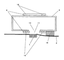
まず、図1は本発明の実施の形態1における空気調和機のフィルタ装置の構成を示した斜視図である。この図において熱交換器を通過する空気の塵埃を除去するエアフィルタは、フィルタ枠1と、フィルタ網2から構成され、そのエアフィルタの表面に沿って移動可能な吸引ノズル3が設けられる(吸引ノズル3の構造詳細については後に記述するため、ここでの詳細記述は割愛する)。吸引ノズル3はフィルタ枠の上下端に設置されたガイドレール4により、エアフィルタと極めて狭い間隙を保って円滑に左右に移動することができる。エアフィルタ上に付着した塵埃はこの吸引ノズル3より吸引される。さらに、吸引ノズル3には吸引ダクト5が連結され、さらに吸引ダクト5は吸引装置6に連結される。吸引ダクト5は吸引ノズル3の移動に差し支えないように折り曲げ可能なダクトで形成される。さらに、吸引装置6には排気ダクト7が連結され、室外へ引き回される。吸引ノズル3により吸引されたエアフィルタの塵埃は吸引ダクト5、吸引装置6、排気ダクト7を経由して室外へ排出される。
First, FIG. 1 is a perspective view showing a configuration of a filter device of an air conditioner according to
次に、図2、図3、を用いて吸引ノズル3の構造詳細を説明する。図2は、上記フィルタ装置の構成における、吸引ノズル3の構造を示した図であり、吸引ノズルを斜め上方向から見た図である。吸引ノズル3は主に、吸引した風の流通路となるノズル8と、ノズル8を囲むように設けられた幅20mmのベルト9から構成される。ノズル8のエアフィルタ側の面には、320mmの長さ(フィルタの縦長さに相当)で、幅は3mmのスリット状のノズル開口部10が設けてある。一方、ベルト9はループ状に形成され、ノズル開口部10を覆うようにノズル8の外周に巻き付けられる。ベルト9には長さ80mm(フィルタの縦長さの1/4)で幅2mmの吸引孔11が設けてあり、吸引孔11の位置はノズル開口部10の真上にくるようにベルト9は取り付けられる。ベルト9の両端には映画フィルムのように等間隔の駆動穴12が設けられており、ノズル8上に固定されたステッピングモータ13に取り付けられた歯車14が、この駆動穴12にかみ合わさることによってベルト9は上下方向のいずれにも自由に駆動できるようになっている。図3は図2におけるノズル8とベルト9を別々にして示した図である。また、図5は吸引ノズル3の断面図である。吸引ノズル3において、ブラシ15をベルト9に沿って横に配置しており、ブラシ15は起毛布の毛足の短いもの(いわゆるエチケットブラシ)などを用いるのが良い。ブラシ15はエアフィルタ上に強く付着してしまって吸引清掃だけでは除去しきれない塵埃も掻き取ることできるので、この効果を利用してより高性能なフィルタ清掃を行うことが可能となる。
Next, the detailed structure of the suction nozzle 3 will be described with reference to FIGS. 2 and 3. FIG. 2 is a view showing the structure of the suction nozzle 3 in the configuration of the filter device, and is a view of the suction nozzle as seen from an obliquely upward direction. The suction nozzle 3 is mainly composed of a
以上のような構成により、吸引装置6によって吸引される風量は吸引孔11に絞られて集中することとなるので、少ない風量でも吸引孔11部分では強い風速を発生させることが可能となる。すなわち、小出力で強い吸引力を発揮することが可能となる。この強い吸引力で吸引されたフィルタ上の塵埃は、吸引孔11からノズル開口部10を経てノズル8内部に入り、さらに吸引ダクト5、吸引装置6、排気ダクト7を経由して室外へ排出される。
With the configuration described above, the air volume sucked by the suction device 6 is concentrated and concentrated in the
本実施の形態においては上記構成の吸引ノズル3にてエアフィルタの全面を吸引清掃を
行うので、その具体的動作について、図1、図4、図6、図7、図8を用いて説明する。図4は図1に記載したエアフィルタの清掃範囲A,B,C,Dに応じた吸引孔の位置を示した図(吸引ノズルを背面から見た図)である。なお、実際の吸引ノズル3は図1に示されるように、エアフィルタに沿って折れ曲がった構造をとるが、図4においては見やすくするため吸引ノズル3を真直に伸ばした状態で記載している。まず、図1におけるエアフィルタのAの範囲を吸引清掃する場合、ベルト9を駆動して吸引孔11を図4のAの位置に固定する。この状態で吸引しながら吸引ノズル3をエアフィルタの右端から左端まで駆動することで図1におけるエアフィルタのAの範囲が吸引清掃できる。次に、図1におけるエアフィルタのBの範囲の吸引清掃に移行するため、ベルト9を駆動して吸引孔11を図4のBの位置に固定する。同様に、この状態で吸引しながら吸引ノズル3をエアフィルタの左端から右端まで駆動することで今度は図1におけるエアフィルタのBの範囲が吸引清掃できる。同様にして図1におけるエアフィルタのC、Dの範囲も吸引清掃できる。図6はこの吸引清掃の順序を矢印にて示した図であるが、左右駆動電気モータ16により横スイープの吸引動作を行うことでエアフィルタ全面を清掃することができる。本実施の形態における風量は、ノズル開口部全域から吸引する場合の必要動力と比較すると風量は1/4であり、必要動力は風量の3乗に比例するので1/64まで低減できる。このように吸引装置6に必要とされる動力は極めて小さいもので済ますことができる。
In the present embodiment, since the entire surface of the air filter is suction-cleaned by the suction nozzle 3 having the above-described configuration, the specific operation will be described with reference to FIGS. 1, 4, 6, 7, and 8. . FIG. 4 is a view showing the positions of the suction holes corresponding to the cleaning ranges A, B, C, and D of the air filter shown in FIG. As shown in FIG. 1, the actual suction nozzle 3 has a structure bent along the air filter. However, in FIG. 4, the suction nozzle 3 is illustrated as being straightened for easy viewing. First, when the area A of the air filter in FIG. 1 is suction-cleaned, the
図7においてブラシ15を向かって左に移動する際、比較的強度の弱いフィルタ網2の部分はブラシ15の押し付け圧力によりたわみやすい。それに対してフィルタ枠1は比較的強度が強いためブラシ15の押し付け圧力によりたわみにくい。それによりフィルタ枠1をブラシ15が通過する際、段差となりブラシ15とフィルタ枠1との間に抵抗が生じる。この抵抗が図6における左右駆動電気モータ16の負荷となり、左右駆動電気モータ16の信頼性の低下を招いてしまう。
In FIG. 7, when moving to the left toward the
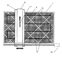
図8においてフィルタ枠1を構成する桟1aは斜め45度の角度をつけて構成されている。これによりブラシ15とフィルタ枠1との接触面積を一定に保つ事ができ、ブラシ15とフィルタ枠1との間に抵抗の変動を少なくできる。従って左右駆動電気モータ16の負荷変動を少なくすることができ、信頼性の向上を図る事ができる。
In FIG. 8, the crosspieces 1a constituting the
(実施の形態2)
本発明の実施の形態2について、図9を用いて説明する。フィルタ枠1の強度を保ったまま縦桟1bの太さを細くし本数を増加させる。これによりブラシ15がフィルタ枠1を乗り上げる際の抵抗を減少させることができ、左右駆動電気モータ16の負荷変動を少なくすることができ、信頼性の向上を図る事ができる。
(Embodiment 2)
(実施の形態3)
本発明の実施の形態3について、図10を用いて説明する。フィルタ枠1の桟の構成を蜂の巣状(ハニカム形状)桟1cとすることによりフィルタ枠の強度を保ったままブラシ15とフィルタ枠1の乗り上げ抵抗を一定に保つことができ、左右駆動電気モータ16の負荷変動を少なくすることができ、左右駆動電気モータ信頼性の向上を図る事ができる。
(Embodiment 3)
A third embodiment of the present invention will be described with reference to FIG. By making the crosspieces of the
(実施の形態4)
本発明の実施の形態4について図11を用いて説明する。フィルタ枠1の桟の断面を四角形の形状に代わり曲面形状とする曲面桟1dとすることによりフィルタ枠1の強度を保ったままブラシ15とフィルタ枠1の乗り上げ抵抗を減少させることができ、左右駆動電気モータ16の負荷変動を少なくすることができ、左右駆動電気モータ信頼性の向上を図る事ができる。
(Embodiment 4)
A fourth embodiment of the present invention will be described with reference to FIG. By setting the cross section of the crosspiece of the
(実施の形態5)
本発明の実施の形態5について説明する。フィルタ枠1は通常樹脂を用いて成形されるが、フィルタ枠1およびフィルタ網2の材質を金属製とすることによりブラシ15がかける圧力によるたわみ量を少なくさせ、ブラシ15とフィルタ枠1の乗り上げ抵抗を減少させることができ、左右駆動電気モータ16の負荷変動を少なくすることができ、左右駆動電気モータ信頼性の向上を図る事ができる。
(Embodiment 5)
Embodiment 5 of the present invention will be described. The
以上のように、本発明にかかる空気調和機のフィルタ装置は、エアフィルターに付着する塵埃を吸引ノズルによる吸引およびブラシによって自動清掃する機能を有する空気調和機において、フィルタ枠の桟を斜めに配置することによりブラシとフィルタ枠の抵抗を減少させることができ、左右駆動電気モータの信頼性を向上することが可能となるので、種々の空気調和機にも適用できる。 As described above, the filter device of the air conditioner according to the present invention is configured such that the filter frame crosspieces are arranged obliquely in the air conditioner having a function of sucking dust adhering to the air filter by the suction nozzle and automatically cleaning with the brush. By doing so, the resistance of the brush and the filter frame can be reduced, and the reliability of the left and right drive electric motor can be improved. Therefore, the present invention can also be applied to various air conditioners.
1 フィルタ枠
1a 桟
1b 縦桟
1c 蜂の巣状桟
2 フィルタ網
3 吸引ノズル
4 ガイドレール
5 吸引ダクト
6 吸引装置
7 排気ダクト
8 ノズル
9 ベルト
10 ノズル開口部
11 吸引孔
12 駆動穴
13 ステッピングモータ
14 歯車
15 ブラシ
16 左右駆動用電気モータ
DESCRIPTION OF
Claims (5)
Priority Applications (1)
| Application Number | Priority Date | Filing Date | Title |
|---|---|---|---|
| JP2004299876A JP2006112699A (en) | 2004-10-14 | 2004-10-14 | Filter device of air conditioner |
Applications Claiming Priority (1)
| Application Number | Priority Date | Filing Date | Title |
|---|---|---|---|
| JP2004299876A JP2006112699A (en) | 2004-10-14 | 2004-10-14 | Filter device of air conditioner |
Related Child Applications (1)
| Application Number | Title | Priority Date | Filing Date |
|---|---|---|---|
| JP2008161337A Division JP2008267803A (en) | 2008-06-20 | 2008-06-20 | Air conditioner |
Publications (1)
| Publication Number | Publication Date |
|---|---|
| JP2006112699A true JP2006112699A (en) | 2006-04-27 |
Family
ID=36381357
Family Applications (1)
| Application Number | Title | Priority Date | Filing Date |
|---|---|---|---|
| JP2004299876A Pending JP2006112699A (en) | 2004-10-14 | 2004-10-14 | Filter device of air conditioner |
Country Status (1)
| Country | Link |
|---|---|
| JP (1) | JP2006112699A (en) |
Cited By (8)
| Publication number | Priority date | Publication date | Assignee | Title |
|---|---|---|---|---|
| WO2008047662A1 (en) | 2006-10-19 | 2008-04-24 | Daikin Industries, Ltd. | Air conditioner with filter cleaning unit |
| JP2008111599A (en) * | 2006-10-31 | 2008-05-15 | Matsushita Electric Ind Co Ltd | Filter device for air conditioner |
| JP2008111580A (en) * | 2006-10-30 | 2008-05-15 | Mitsubishi Electric Corp | Filter cleaning device and air conditioner |
| JP2008190836A (en) * | 2007-02-08 | 2008-08-21 | Matsushita Electric Ind Co Ltd | Air conditioner |
| JP2008194574A (en) * | 2007-02-09 | 2008-08-28 | Matsushita Electric Ind Co Ltd | Air conditioner |
| JP2010019498A (en) * | 2008-07-11 | 2010-01-28 | Hitachi Appliances Inc | Air conditioner |
| CN109798598A (en) * | 2019-02-25 | 2019-05-24 | 安徽宏凤空调滤网有限公司 | A kind of air-conditioning filter net |
| CN110207284A (en) * | 2019-05-05 | 2019-09-06 | 安徽皖华环保设备科技有限公司 | A kind of indoor air purification equipment |
-
2004
- 2004-10-14 JP JP2004299876A patent/JP2006112699A/en active Pending
Cited By (11)
| Publication number | Priority date | Publication date | Assignee | Title |
|---|---|---|---|---|
| WO2008047662A1 (en) | 2006-10-19 | 2008-04-24 | Daikin Industries, Ltd. | Air conditioner with filter cleaning unit |
| JP2008111580A (en) * | 2006-10-30 | 2008-05-15 | Mitsubishi Electric Corp | Filter cleaning device and air conditioner |
| JP4533366B2 (en) * | 2006-10-30 | 2010-09-01 | 三菱電機株式会社 | Filter, filter cleaning device, and air conditioner |
| JP2008111599A (en) * | 2006-10-31 | 2008-05-15 | Matsushita Electric Ind Co Ltd | Filter device for air conditioner |
| JP2008190836A (en) * | 2007-02-08 | 2008-08-21 | Matsushita Electric Ind Co Ltd | Air conditioner |
| JP2008194574A (en) * | 2007-02-09 | 2008-08-28 | Matsushita Electric Ind Co Ltd | Air conditioner |
| JP2010019498A (en) * | 2008-07-11 | 2010-01-28 | Hitachi Appliances Inc | Air conditioner |
| CN109798598A (en) * | 2019-02-25 | 2019-05-24 | 安徽宏凤空调滤网有限公司 | A kind of air-conditioning filter net |
| CN109798598B (en) * | 2019-02-25 | 2020-09-22 | 安徽宏凤空调滤网有限公司 | Air conditioner filter screen |
| CN110207284A (en) * | 2019-05-05 | 2019-09-06 | 安徽皖华环保设备科技有限公司 | A kind of indoor air purification equipment |
| CN110207284B (en) * | 2019-05-05 | 2021-03-26 | 安徽皖华环保设备科技有限公司 | Indoor air purification equipment |
Similar Documents
| Publication | Publication Date | Title |
|---|---|---|
| JP4050774B2 (en) | Air conditioner | |
| JP3918789B2 (en) | Air conditioner | |
| JP2006112699A (en) | Filter device of air conditioner | |
| JP5240020B2 (en) | Air conditioner | |
| JP2008267803A (en) | Air conditioner | |
| JP4533366B2 (en) | Filter, filter cleaning device, and air conditioner | |
| EP2072929A1 (en) | Air conditioner | |
| JP4185542B2 (en) | Filter and air conditioner using the same | |
| JP3918802B2 (en) | Air conditioner | |
| JP2006284044A (en) | Filter device for air conditioner | |
| JP4645059B2 (en) | Filter device and air conditioner | |
| JP4014619B2 (en) | Air conditioner | |
| JP2007107827A (en) | Filter device of air conditioner | |
| JP2008111599A (en) | Filter device for air conditioner | |
| JP2005140405A (en) | Air conditioner | |
| JP4599970B2 (en) | Air conditioner | |
| JP4599982B2 (en) | Air conditioner filter device | |
| JP2007101106A (en) | Filter device for air conditioner | |
| JP4449703B2 (en) | Air conditioner filter device | |
| JP2006322682A (en) | Air conditioner | |
| JP4550743B2 (en) | Filter cleaning device | |
| JP4507758B2 (en) | Air conditioner filter device | |
| JP2010096407A (en) | Air conditioner | |
| JP4449564B2 (en) | Filter device and air conditioner | |
| JP2006284136A (en) | Filter device for air-conditioner |
Legal Events
| Date | Code | Title | Description |
|---|---|---|---|
| A977 | Report on retrieval |
Free format text: JAPANESE INTERMEDIATE CODE: A971007 Effective date: 20080411 |
|
| A131 | Notification of reasons for refusal |
Free format text: JAPANESE INTERMEDIATE CODE: A131 Effective date: 20080422 |
|
| A02 | Decision of refusal |
Free format text: JAPANESE INTERMEDIATE CODE: A02 Effective date: 20080924 |