JP2006106076A - Manufacturing method of thin film semiconductor device, thin film semiconductor device, electrooptical device, and electronic device - Google Patents
Manufacturing method of thin film semiconductor device, thin film semiconductor device, electrooptical device, and electronic device Download PDFInfo
- Publication number
- JP2006106076A JP2006106076A JP2004288677A JP2004288677A JP2006106076A JP 2006106076 A JP2006106076 A JP 2006106076A JP 2004288677 A JP2004288677 A JP 2004288677A JP 2004288677 A JP2004288677 A JP 2004288677A JP 2006106076 A JP2006106076 A JP 2006106076A
- Authority
- JP
- Japan
- Prior art keywords
- film
- electro
- thin film
- semiconductor
- insulating film
- Prior art date
- Legal status (The legal status is an assumption and is not a legal conclusion. Google has not performed a legal analysis and makes no representation as to the accuracy of the status listed.)
- Granted
Links
- 239000004065 semiconductor Substances 0.000 title claims abstract description 102
- 239000010409 thin film Substances 0.000 title claims abstract description 37
- 238000004519 manufacturing process Methods 0.000 title claims abstract description 30
- 239000010408 film Substances 0.000 claims abstract description 305
- 239000000758 substrate Substances 0.000 claims abstract description 99
- 239000012535 impurity Substances 0.000 claims abstract description 49
- 238000005530 etching Methods 0.000 claims abstract description 25
- 239000003990 capacitor Substances 0.000 claims description 49
- 239000010410 layer Substances 0.000 claims description 41
- 238000000034 method Methods 0.000 claims description 34
- 239000004973 liquid crystal related substance Substances 0.000 claims description 30
- 239000000463 material Substances 0.000 claims description 15
- 239000011159 matrix material Substances 0.000 claims description 10
- 238000003860 storage Methods 0.000 abstract description 37
- 230000015572 biosynthetic process Effects 0.000 description 13
- 239000011229 interlayer Substances 0.000 description 12
- 150000002500 ions Chemical class 0.000 description 12
- 230000002093 peripheral effect Effects 0.000 description 11
- VYPSYNLAJGMNEJ-UHFFFAOYSA-N Silicium dioxide Chemical compound O=[Si]=O VYPSYNLAJGMNEJ-UHFFFAOYSA-N 0.000 description 10
- 229910052814 silicon oxide Inorganic materials 0.000 description 10
- -1 phosphorus ions Chemical class 0.000 description 8
- 229910052782 aluminium Inorganic materials 0.000 description 6
- XAGFODPZIPBFFR-UHFFFAOYSA-N aluminium Chemical compound [Al] XAGFODPZIPBFFR-UHFFFAOYSA-N 0.000 description 6
- 229910052698 phosphorus Inorganic materials 0.000 description 6
- 239000011574 phosphorus Substances 0.000 description 6
- 230000001681 protective effect Effects 0.000 description 6
- 239000007789 gas Substances 0.000 description 5
- 239000011347 resin Substances 0.000 description 5
- 229920005989 resin Polymers 0.000 description 5
- ZOKXTWBITQBERF-UHFFFAOYSA-N Molybdenum Chemical compound [Mo] ZOKXTWBITQBERF-UHFFFAOYSA-N 0.000 description 4
- 229910052581 Si3N4 Inorganic materials 0.000 description 4
- 238000010586 diagram Methods 0.000 description 4
- 229910052750 molybdenum Inorganic materials 0.000 description 4
- 239000011733 molybdenum Substances 0.000 description 4
- 238000000206 photolithography Methods 0.000 description 4
- 229920001721 polyimide Polymers 0.000 description 4
- HQVNEWCFYHHQES-UHFFFAOYSA-N silicon nitride Chemical compound N12[Si]34N5[Si]62N3[Si]51N64 HQVNEWCFYHHQES-UHFFFAOYSA-N 0.000 description 4
- 229910052715 tantalum Inorganic materials 0.000 description 4
- GUVRBAGPIYLISA-UHFFFAOYSA-N tantalum atom Chemical compound [Ta] GUVRBAGPIYLISA-UHFFFAOYSA-N 0.000 description 4
- 230000005540 biological transmission Effects 0.000 description 3
- 239000011521 glass Substances 0.000 description 3
- 229910052751 metal Inorganic materials 0.000 description 3
- 239000002184 metal Substances 0.000 description 3
- 230000003287 optical effect Effects 0.000 description 3
- 239000003566 sealing material Substances 0.000 description 3
- MYMOFIZGZYHOMD-UHFFFAOYSA-N Dioxygen Chemical compound O=O MYMOFIZGZYHOMD-UHFFFAOYSA-N 0.000 description 2
- BOTDANWDWHJENH-UHFFFAOYSA-N Tetraethyl orthosilicate Chemical compound CCO[Si](OCC)(OCC)OCC BOTDANWDWHJENH-UHFFFAOYSA-N 0.000 description 2
- 239000000853 adhesive Substances 0.000 description 2
- 230000001070 adhesive effect Effects 0.000 description 2
- 239000000956 alloy Substances 0.000 description 2
- 229910045601 alloy Inorganic materials 0.000 description 2
- 229910021417 amorphous silicon Inorganic materials 0.000 description 2
- 229910052796 boron Inorganic materials 0.000 description 2
- 239000004020 conductor Substances 0.000 description 2
- 229910001882 dioxygen Inorganic materials 0.000 description 2
- 238000009413 insulation Methods 0.000 description 2
- 238000005224 laser annealing Methods 0.000 description 2
- 239000012528 membrane Substances 0.000 description 2
- 150000002739 metals Chemical class 0.000 description 2
- 238000005268 plasma chemical vapour deposition Methods 0.000 description 2
- 238000004544 sputter deposition Methods 0.000 description 2
- 238000004506 ultrasonic cleaning Methods 0.000 description 2
- OYPRJOBELJOOCE-UHFFFAOYSA-N Calcium Chemical compound [Ca] OYPRJOBELJOOCE-UHFFFAOYSA-N 0.000 description 1
- 239000004593 Epoxy Substances 0.000 description 1
- PXGOKWXKJXAPGV-UHFFFAOYSA-N Fluorine Chemical compound FF PXGOKWXKJXAPGV-UHFFFAOYSA-N 0.000 description 1
- WHXSMMKQMYFTQS-UHFFFAOYSA-N Lithium Chemical compound [Li] WHXSMMKQMYFTQS-UHFFFAOYSA-N 0.000 description 1
- BQCADISMDOOEFD-UHFFFAOYSA-N Silver Chemical compound [Ag] BQCADISMDOOEFD-UHFFFAOYSA-N 0.000 description 1
- QVGXLLKOCUKJST-UHFFFAOYSA-N atomic oxygen Chemical compound [O] QVGXLLKOCUKJST-UHFFFAOYSA-N 0.000 description 1
- 239000011324 bead Substances 0.000 description 1
- 229910052791 calcium Inorganic materials 0.000 description 1
- 239000011575 calcium Substances 0.000 description 1
- 230000001413 cellular effect Effects 0.000 description 1
- 230000000295 complement effect Effects 0.000 description 1
- 238000001312 dry etching Methods 0.000 description 1
- 230000009977 dual effect Effects 0.000 description 1
- 238000005401 electroluminescence Methods 0.000 description 1
- 239000000835 fiber Substances 0.000 description 1
- 239000011737 fluorine Substances 0.000 description 1
- 229910052731 fluorine Inorganic materials 0.000 description 1
- 239000003365 glass fiber Substances 0.000 description 1
- AMGQUBHHOARCQH-UHFFFAOYSA-N indium;oxotin Chemical compound [In].[Sn]=O AMGQUBHHOARCQH-UHFFFAOYSA-N 0.000 description 1
- 238000002347 injection Methods 0.000 description 1
- 239000007924 injection Substances 0.000 description 1
- 229910052744 lithium Inorganic materials 0.000 description 1
- 230000014759 maintenance of location Effects 0.000 description 1
- 229910052760 oxygen Inorganic materials 0.000 description 1
- 239000001301 oxygen Substances 0.000 description 1
- 239000002245 particle Substances 0.000 description 1
- 238000000016 photochemical curing Methods 0.000 description 1
- 230000000717 retained effect Effects 0.000 description 1
- 229920001187 thermosetting polymer Polymers 0.000 description 1
Images


Classifications
-
- H—ELECTRICITY
- H01—ELECTRIC ELEMENTS
- H01L—SEMICONDUCTOR DEVICES NOT COVERED BY CLASS H10
- H01L27/00—Devices consisting of a plurality of semiconductor or other solid-state components formed in or on a common substrate
- H01L27/02—Devices consisting of a plurality of semiconductor or other solid-state components formed in or on a common substrate including semiconductor components specially adapted for rectifying, oscillating, amplifying or switching and having at least one potential-jump barrier or surface barrier; including integrated passive circuit elements with at least one potential-jump barrier or surface barrier
- H01L27/12—Devices consisting of a plurality of semiconductor or other solid-state components formed in or on a common substrate including semiconductor components specially adapted for rectifying, oscillating, amplifying or switching and having at least one potential-jump barrier or surface barrier; including integrated passive circuit elements with at least one potential-jump barrier or surface barrier the substrate being other than a semiconductor body, e.g. an insulating body
- H01L27/1214—Devices consisting of a plurality of semiconductor or other solid-state components formed in or on a common substrate including semiconductor components specially adapted for rectifying, oscillating, amplifying or switching and having at least one potential-jump barrier or surface barrier; including integrated passive circuit elements with at least one potential-jump barrier or surface barrier the substrate being other than a semiconductor body, e.g. an insulating body comprising a plurality of TFTs formed on a non-semiconducting substrate, e.g. driving circuits for AMLCDs
- H01L27/1255—Devices consisting of a plurality of semiconductor or other solid-state components formed in or on a common substrate including semiconductor components specially adapted for rectifying, oscillating, amplifying or switching and having at least one potential-jump barrier or surface barrier; including integrated passive circuit elements with at least one potential-jump barrier or surface barrier the substrate being other than a semiconductor body, e.g. an insulating body comprising a plurality of TFTs formed on a non-semiconducting substrate, e.g. driving circuits for AMLCDs integrated with passive devices, e.g. auxiliary capacitors
-
- H—ELECTRICITY
- H01—ELECTRIC ELEMENTS
- H01L—SEMICONDUCTOR DEVICES NOT COVERED BY CLASS H10
- H01L27/00—Devices consisting of a plurality of semiconductor or other solid-state components formed in or on a common substrate
- H01L27/02—Devices consisting of a plurality of semiconductor or other solid-state components formed in or on a common substrate including semiconductor components specially adapted for rectifying, oscillating, amplifying or switching and having at least one potential-jump barrier or surface barrier; including integrated passive circuit elements with at least one potential-jump barrier or surface barrier
- H01L27/12—Devices consisting of a plurality of semiconductor or other solid-state components formed in or on a common substrate including semiconductor components specially adapted for rectifying, oscillating, amplifying or switching and having at least one potential-jump barrier or surface barrier; including integrated passive circuit elements with at least one potential-jump barrier or surface barrier the substrate being other than a semiconductor body, e.g. an insulating body
- H01L27/1214—Devices consisting of a plurality of semiconductor or other solid-state components formed in or on a common substrate including semiconductor components specially adapted for rectifying, oscillating, amplifying or switching and having at least one potential-jump barrier or surface barrier; including integrated passive circuit elements with at least one potential-jump barrier or surface barrier the substrate being other than a semiconductor body, e.g. an insulating body comprising a plurality of TFTs formed on a non-semiconducting substrate, e.g. driving circuits for AMLCDs
-
- H—ELECTRICITY
- H01—ELECTRIC ELEMENTS
- H01L—SEMICONDUCTOR DEVICES NOT COVERED BY CLASS H10
- H01L27/00—Devices consisting of a plurality of semiconductor or other solid-state components formed in or on a common substrate
- H01L27/02—Devices consisting of a plurality of semiconductor or other solid-state components formed in or on a common substrate including semiconductor components specially adapted for rectifying, oscillating, amplifying or switching and having at least one potential-jump barrier or surface barrier; including integrated passive circuit elements with at least one potential-jump barrier or surface barrier
- H01L27/12—Devices consisting of a plurality of semiconductor or other solid-state components formed in or on a common substrate including semiconductor components specially adapted for rectifying, oscillating, amplifying or switching and having at least one potential-jump barrier or surface barrier; including integrated passive circuit elements with at least one potential-jump barrier or surface barrier the substrate being other than a semiconductor body, e.g. an insulating body
- H01L27/13—Devices consisting of a plurality of semiconductor or other solid-state components formed in or on a common substrate including semiconductor components specially adapted for rectifying, oscillating, amplifying or switching and having at least one potential-jump barrier or surface barrier; including integrated passive circuit elements with at least one potential-jump barrier or surface barrier the substrate being other than a semiconductor body, e.g. an insulating body combined with thin-film or thick-film passive components
Abstract
Description
本発明は、薄膜トランジスタ(以下、TFTという)と容量素子が同一基板上に備えた薄膜半導体装置、その製造方法、当該薄膜半導体装置を電気光学装置用基板として用いた電気光学装置、およびこの電気光学装置を備えた電子機器に関するものである。さらに詳しくは、静電容量の高い容量素子の製造技術に関するものである。 The present invention relates to a thin film semiconductor device in which a thin film transistor (hereinafter referred to as TFT) and a capacitive element are provided on the same substrate, a manufacturing method thereof, an electro-optical device using the thin film semiconductor device as a substrate for an electro-optical device, and the electro-optical device The present invention relates to an electronic device including the device. More specifically, the present invention relates to a manufacturing technique of a capacitive element having a high capacitance.
TFTと容量素子を同一基板上に備えた薄膜半導体装置を構成する場合、TFTの半導体膜と同層の半導体膜を導電化して下電極を形成し、ゲート絶縁膜と同層の絶縁膜を用いて誘電体膜を形成し、ゲート電極と同層の導電膜を用いて上電極を形成すれば、少ない工程数でTFTと容量素子とを形成することができる。このような構造は、画素スイッチング用の非線形素子としてTFTを用いた液晶装置(電気光学装置)の素子基板や各種薄膜半導体装置で多用されている。 When configuring a thin film semiconductor device having a TFT and a capacitor on the same substrate, a semiconductor film in the same layer as the TFT semiconductor film is made conductive to form a lower electrode, and an insulating film in the same layer as the gate insulating film is used. If the dielectric film is formed and the upper electrode is formed using the conductive film in the same layer as the gate electrode, the TFT and the capacitor can be formed with a small number of steps. Such a structure is widely used in an element substrate of a liquid crystal device (electro-optical device) using TFTs as nonlinear elements for pixel switching and various thin film semiconductor devices.
しかしながら、容量素子では、誘電体膜の膜厚が薄ければ、大きな静電容量を得ることができる一方、TFTでは、ゲート絶縁膜が薄ければ、耐電圧が低下してしまう。そこで、容量素子の側において、ゲート絶縁膜と同時形成した絶縁膜を薄膜化して誘電体膜を形成した構造が提案されている(例えば、特許文献1参照)。
しかしながら、容量素子の誘電体膜の膜厚とTFTのゲート絶縁膜の膜厚を相違させる場合には、容量素子の誘電体膜をエッチングして薄くするためのマスクを追加しなければならない。そのため、マスク形成工程およびマスク除去工程を各々、1工程ずつ増やす必要があり、生産性が低下するという問題点がある。 However, if the film thickness of the dielectric film of the capacitive element is different from the film thickness of the gate insulating film of the TFT, a mask for etching and thinning the dielectric film of the capacitive element must be added. For this reason, it is necessary to increase the mask forming process and the mask removing process one by one, and there is a problem that productivity is lowered.
以上の問題点に鑑みて、本発明の課題は、製造工程を増やすことなく、容量素子の誘電体膜の膜厚をTFTのゲート絶縁膜の膜厚よりも薄くすることのできる薄膜半導体装置の製造方法、薄膜半導体装置、この薄膜半導体装置を電気光学装置用基板として用いた電気光学装置、およびこの電気光学装置を備えた電子機器を提供することにある。 In view of the above problems, an object of the present invention is to provide a thin film semiconductor device capable of making the thickness of the dielectric film of the capacitor element smaller than the thickness of the gate insulating film of the TFT without increasing the number of manufacturing steps. It is an object of the present invention to provide a manufacturing method, a thin film semiconductor device, an electro optical device using the thin film semiconductor device as a substrate for an electro optical device, and an electronic apparatus including the electro optical device.
上記課題を解決するために、本発明では、第1の半導体膜、ゲート絶縁膜、およびゲート電極が基板側からこの順に積層されたTFTと、前記第1の半導体膜と同層の第2の半導体膜を導電化してなる下電極、前記ゲート絶縁膜と同層の誘電体膜、および前記ゲート電極と同層の上電極が前記基板側からこの順に積層された容量素子とを備えた薄膜半導体装置の製造方法において、前記ゲート絶縁膜および前記誘電体膜を同時形成した以降、前記ゲート電極および前記上電極を形成する前に、前記基板の表面側に形成した前記マスクの第1の開口から前記第2の半導体膜に不純物を導入して前記下電極を形成する下電極形成用不純物導入工程と、前記マスクの前記第1の開口から前記誘電体膜の表面をエッチングする誘電体膜エッチング工程とを行うことを特徴とする。 In order to solve the above problems, in the present invention, a TFT in which a first semiconductor film, a gate insulating film, and a gate electrode are stacked in this order from the substrate side, and a second layer in the same layer as the first semiconductor film are provided. A thin film semiconductor comprising a lower electrode formed by conducting a semiconductor film, a dielectric film in the same layer as the gate insulating film, and a capacitive element in which an upper electrode in the same layer as the gate electrode is stacked in this order from the substrate side In the device manufacturing method, after forming the gate insulating film and the dielectric film at the same time and before forming the gate electrode and the upper electrode, the first opening of the mask formed on the surface side of the substrate is used. Lower electrode forming impurity introduction step for introducing the impurity into the second semiconductor film to form the lower electrode, and dielectric film etching step for etching the surface of the dielectric film from the first opening of the mask And performing.
かかる製造方法で製造した薄膜半導体装置では、前記誘電体膜には、当該誘電体膜の膜厚を前記ゲート絶縁膜の膜厚より薄くする第1の凹部が形成され、前記第2の半導体膜では、前記第1の凹部と平面的に重なる領域に不純物が導入されて前記下電極が形成されていることを特徴とする。 In the thin film semiconductor device manufactured by this manufacturing method, the dielectric film is provided with a first recess that makes the thickness of the dielectric film smaller than the thickness of the gate insulating film, and the second semiconductor film. Then, the lower electrode is formed by introducing impurities into a region overlapping the first recess in a plan view.
本願明細書における同層とは薄膜の一部あるいは全体が基板上の同一の層間に同一形成された構造を意味する。 The same layer in the present specification means a structure in which a part or the whole of the thin film is formed in the same layer on the substrate.
本発明では、TFT側の第1の半導体膜と同層の第2の半導体膜を導電化してなる下電極、TFT側のゲート絶縁膜と同層の誘電体膜、およびTFT側のゲート電極と同層の上電極が基板側からこの順に積層されて容量素子が構成されており、かかる容量素子の下電極を製造するには、ゲート絶縁膜および誘電体膜を同時形成した以降、ゲート電極および上電極を形成する前にマスクの第1の開口から第2の半導体膜に不純物を導入する工程が必要である。本発明では、このマスクを利用して、その第1の開口から誘電体膜の表面をエッチングするため、1枚のマスクで下電極形成用不純物導入工程と誘電体膜エッチング工程と行うことができる。従って、本発明によれば、製造工程を増やすことなく、容量素子の誘電体膜の膜厚をTFTのゲート絶縁膜の膜厚よりも薄くすることができる。 In the present invention, a lower electrode formed by conducting a second semiconductor film in the same layer as the first semiconductor film on the TFT side, a dielectric film in the same layer as the gate insulating film on the TFT side, and a gate electrode on the TFT side The upper electrode of the same layer is laminated in this order from the substrate side to form a capacitor element. To manufacture the lower electrode of the capacitor element, after forming the gate insulating film and the dielectric film simultaneously, Before forming the upper electrode, it is necessary to introduce an impurity into the second semiconductor film from the first opening of the mask. In the present invention, since the surface of the dielectric film is etched from the first opening by using this mask, the lower electrode forming impurity introducing step and the dielectric film etching step can be performed with one mask. . Therefore, according to the present invention, the thickness of the dielectric film of the capacitive element can be made thinner than the thickness of the gate insulating film of the TFT without increasing the number of manufacturing steps.
本発明において、前記マスクには、前記TFTのうち、前記不純物と同一の導電型のTFTの前記第1の半導体膜にソース・ドレイン領域の一部あるいは全部を形成するための第2の開口を形成し、前記下電極形成用不純物導入工程では、前記第1の開口および前記第2の開口から前記第2の半導体膜および前記第1の半導体膜に不純物を導入し、前記誘電体膜エッチング工程では、前記第1の開口および前記第2の開口から前記誘電体膜の表面および前記ゲート絶縁膜の表面をエッチングすることが好ましい。かかる製造方法で製造した薄膜半導体装置では、前記TFTのうち、前記不純物と同一の導電型のTFTでは、前記ゲート絶縁膜に対して、ソース・ドレイン領域の一部あるいは全部と平面的に重なる領域の当該ゲート絶縁膜の膜厚を前記ゲート電極と平面的に重なる領域の前記ゲート絶縁膜の膜厚よりも薄くする第2の凹部が形成されている。 In the present invention, the mask has a second opening for forming part or all of a source / drain region in the first semiconductor film of the TFT having the same conductivity type as the impurity out of the TFT. Forming and introducing the impurity into the second semiconductor film and the first semiconductor film from the first opening and the second opening, and in the dielectric film etching process Then, it is preferable to etch the surface of the dielectric film and the surface of the gate insulating film from the first opening and the second opening. In a thin film semiconductor device manufactured by such a manufacturing method, in the TFT having the same conductivity type as the impurity, in the TFT, a region overlapping in plan or part of the source / drain region with respect to the gate insulating film A second recess is formed to make the thickness of the gate insulating film thinner than the thickness of the gate insulating film in a region overlapping the gate electrode in a plan view.
ここで、前記ソース・ドレイン領域が、前記ゲート電極にセルフアライン的に形成された低濃度ソース・ドレイン領域と、該低濃度ソース・ドレイン領域に隣接する高濃度ソース・ドレイン領域とを備えている場合には、前記第2の開口を、前記高濃度ソース・ドレイン領域を形成すべき領域に形成する。このように構成すると、下電極形成用不純物導入工程で高濃度ソース・ドレイン領域を形成できるので、マスクの枚数が1枚減る。このため、マスク形成工程およびマスク除去工程を各々、1工程ずつ減らすことができるので、生産性が向上する。かかる製造方法で製造した薄膜半導体装置では、前記ソース・ドレイン領域は、前記ゲート電極にセルフアライン的に形成された低濃度ソース・ドレイン領域と、該低濃度ソース・ドレイン領域に隣接する高濃度ソース・ドレイン領域とを備え、前記第2の凹部は、前記高濃度ソース・ドレイン領域と平面的に重なる領域に形成されている。 Here, the source / drain region includes a low concentration source / drain region formed in a self-aligned manner on the gate electrode, and a high concentration source / drain region adjacent to the low concentration source / drain region. In this case, the second opening is formed in a region where the high concentration source / drain region is to be formed. With this configuration, the high-concentration source / drain regions can be formed in the lower electrode forming impurity introduction step, so that the number of masks is reduced by one. For this reason, since the mask formation process and the mask removal process can be reduced by one process, productivity is improved. In the thin film semiconductor device manufactured by such a manufacturing method, the source / drain region includes a low concentration source / drain region formed in a self-aligned manner on the gate electrode and a high concentration source adjacent to the low concentration source / drain region. A drain region, and the second recess is formed in a region overlapping the high-concentration source / drain region in a planar manner.
本発明において、前記誘電体膜エッチング工程は、前記下電極形成用不純物導入工程の後、前記誘電体膜および前記マスクをエッチング除去可能なエッチャントを用いて行うことが好ましい。このように構成すると、誘電体膜エッチング工程でマスクの除去もできるので、マスクの除去工程を省略でき、生産性がさらに向上する。 In the present invention, the dielectric film etching step is preferably performed using an etchant capable of removing the dielectric film and the mask by etching after the lower electrode forming impurity introduction step. With this configuration, the mask can be removed in the dielectric film etching step, so that the mask removal step can be omitted and the productivity is further improved.
本発明に係る薄膜半導体装置は、例えば、電気光学装置において、電気光学物質を保持する電気光学装置用基板として用いられる。ここで、前記電気光学物質は、例えば、前記電気光学装置用基板と、該電気光学装置用基板に対向配置された対向基板との間に保持された液晶であり、前記TFTおよび前記容量素子は、マトリクス状に配置された複数の画素の各々に構成されている。また、前記電気光学物質は、前記電気光学装置用基板上に構成された有機エレクトロルミネッセンス材料であってもよく、この場合も、前記TFTおよび前記容量素子は、マトリクス状に配置された複数の画素の各々に構成されることになる。 The thin film semiconductor device according to the present invention is used, for example, as an electro-optical device substrate for holding an electro-optical material in an electro-optical device. Here, the electro-optical material is, for example, a liquid crystal held between the electro-optical device substrate and a counter substrate disposed opposite to the electro-optical device substrate, and the TFT and the capacitive element are , Each pixel is arranged in a matrix. The electro-optical material may be an organic electroluminescent material formed on the substrate for the electro-optical device. In this case, the TFT and the capacitive element are a plurality of pixels arranged in a matrix. It will be composed of each.
本発明に係る電気光学装置は、携帯型コンピュータや携帯電話機などといった電子機器において表示部などを構成するのに用いられる。 The electro-optical device according to the present invention is used to configure a display unit or the like in an electronic apparatus such as a portable computer or a mobile phone.
図面を参照して、代表的な電気光学装置である液晶装置に本発明を適用した例を説明する。なお、各図においては、各層や各部材を図面上で認識可能な程度の大きさとするため、各層や各部材毎に縮尺を異ならしめてある。 An example in which the present invention is applied to a liquid crystal device which is a typical electro-optical device will be described with reference to the drawings. In each figure, the scales are different for each layer and each member so that each layer and each member can be recognized on the drawing.
[実施の形態1]
(液晶装置の全体構成)
図1(A)、(B)はそれぞれ、液晶装置をその上に形成された各構成要素と共に対向基板の側から見た平面図、および対向基板を含めて示す図1(A)のH−H′断面図である。
[Embodiment 1]
(Overall configuration of liquid crystal device)
FIGS. 1A and 1B are a plan view of the liquid crystal device viewed from the side of the counter substrate together with each component formed thereon, and H- of FIG. 1A including the counter substrate. It is H 'sectional drawing.
図1(A)、(B)において、液晶装置100(電気光学装置)では、TFTアレイ基板10(薄膜半導体装置)と対向基板20とが、対向基板20の縁に沿うように塗布されたシール材107(図1(A)の右下がりの斜線領域)によって貼り合わされている。また、TFTアレイ基板10と対向基板20との間には、電気光学物質としての液晶50が保持されている。TFTアレイ基板10の外周側には、基板辺111の側でシール材107と一部重なるようにデータ線駆動回路101が形成され、基板辺113、114の側には走査線駆動回路104が形成されている。TFTアレイ基板10において対向基板20からの張り出し領域10cには多数の端子102が形成されている。TFTアレイ基板10において基板辺111と対向する基板辺112には、画像表示領域10aの両側に設けられた走査線駆動回路104同士をつなぐための複数の配線105が形成されている。また、対向基板20の4つのコーナー部には、TFTアレイ基板10と対向基板20との間で電気的導通をとるための基板間導通材106が形成され、この基板間導通材106は、エポキシ樹脂系の接着剤成分に銀粉や金メッキファイバーなどの導電粒子が配合されたものである。なお、シール材107は、光硬化樹脂や熱硬化性樹脂などからなる接着剤であり、両基板間の距離を所定値とするためのグラスファイバー、あるいはガラスビーズ等のギャップ材が配合されている。
1A and 1B, in the liquid crystal device 100 (electro-optical device), a seal in which the TFT array substrate 10 (thin film semiconductor device) and the
詳しくは後述するが、TFTアレイ基板10には、画素電極9aがマトリクス状に形成されている。これに対して、対向基板20には、シール材107の内側領域に遮光性材料からなる周辺見切り用の遮光膜108が形成されている。さらに、対向基板20において、TFTアレイ基板10に形成されている画素電極9aの縦横の境界領域と対向する領域には、ブラックマトリクス、あるいはブラックストライプなどと称せられる遮光膜23が形成され、その上層側には、ITO膜からなる対向電極21が形成されている。
As will be described in detail later,
このように構成した液晶装置100については、後述するように、モバイルコンピュータ、携帯電話機、液晶テレビなどといった電子機器のカラー表示装置として用いる場合には、対向基板20において各画素電極9aに対向する領域にRGBのカラーフィルタ(図示せず)などを形成する。
As will be described later, the
(液晶装置100の構成および動作)
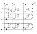
図2は、液晶装置の電気的構成を示すブロック図である。図2に示すように、駆動回路内蔵型のTFTアレイ基板10では、互いに交差する複数のデータ線6aと、複数の走査線3aとが交差する部分に対応して複数の画素100aがマトリクス状に構成されている。複数の画素100aの各々には、画素電極9a、および画素電極9aを制御するための画素スイッチング用のTFT30が形成されており、画素信号を供給するデータ線6aが当該TFT30のソースに電気的に接続されている。データ線6aに書き込む画素信号S1、S2・・・Snは、この順に線順次に供給する。また、TFT30のゲートには走査線3aが電気的に接続されており、所定のタイミングで、走査線3aにパルス的に走査信号G1、G2・・・Gmを、この順に線順次で印加するように構成されている。画素電極9aは、TFT30のドレインに電気的に接続されており、スイッチング素子であるTFT30を一定期間だけそのオン状態とすることにより、データ線6aから供給される画素信号S1、S2・・・Snを各画素に所定のタイミングで書き込む。このようにして画素電極9aを介して液晶に書き込まれた所定レベルの画素信号S1、S2、・・・Snは、図1(B)に示す対向基板20の対向電極21との間で一定期間保持される。
(Configuration and operation of liquid crystal device 100)
FIG. 2 is a block diagram showing an electrical configuration of the liquid crystal device. As shown in FIG. 2, in the
ここで、TFTアレイ基板10には、保持された画素信号がリークするのを防ぐことを目的に、画素電極9aと対向電極21との間に形成される液晶容量と並列に蓄積容量70(容量素子)が付加されている。この蓄積容量70によって、画素電極9aの電圧は、例えば、ソース電圧が印加された時間よりも3桁も長い時間だけ保持される。これにより、電荷の保持特性は改善され、コントラスト比の高い表示を行うことのできる液晶装置100が実現できる。なお、蓄積容量70については、本形態のように、容量線3bとの間に形成する場合の他、前段の走査線3aとの間に形成する場合もある。
Here, the
(TFTアレイ基板の構成)
図3は、TFTアレイ基板において相隣接する画素の平面図である。図4は、図3のA−A′線に相当する位置での断面図である。
(Configuration of TFT array substrate)
FIG. 3 is a plan view of adjacent pixels on the TFT array substrate. FIG. 4 is a cross-sectional view at a position corresponding to the line AA ′ in FIG. 3.
図3において、TFTアレイ基板10上には、複数の透明なITO(Indium Tin Oxide)膜からなる画素電極9aがマトリクス状に形成され、これら画素電極9aに対して画素スイッチング用のTFT30がそれぞれ接続している。また、画素電極9aの縦横の境界に沿って、データ線6a、走査線3a、および容量線3bが形成され、TFT30は、データ線6aおよび走査線3aに対して接続している。すなわち、データ線6aは、コンタクトホールを介してTFT30の高濃度ソース領域1dに電気的に接続し、走査線3aは、その突出部分がTFT30のゲート電極を構成している。蓄積容量70は、画素スイッチング用のTFT30を形成するための半導体膜1aの延設部分1fを導電化したものを下電極1gとし、この下電極1gに重なる容量線3bの矩形部分を上電極3c(上電極)としている。
In FIG. 3,
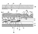
図4に示すように、TFTアレイ基板10では、その基体として透明基板10bが用いられ、この透明基板10bの表面には、厚さが300nm〜500nmのシリコン酸化膜(絶縁膜)からなる下地保護膜11が形成され、この下地保護膜11の表面には、厚さが30nm〜100nmの島状の半導体膜1aが形成されている。半導体膜1aの表面には、厚さが約50〜150nmのシリコン酸化膜などの絶縁膜2からなるゲート絶縁膜2aが形成され、このゲート絶縁膜2aの表面に、厚さが300nm〜800nmの走査線3aが形成されている。半導体膜1aのうち、走査線3aに対してゲート絶縁膜2aを介して対峙する領域がチャネル領域1a′(能動層)になっている。このチャネル領域1a′に対して一方側には、低濃度ソース領域1bおよび高濃度ソース領域1dを備えるソース領域が形成され、他方側には低濃度ドレイン領域1cおよび高濃度ドレイン領域1eを備えるドレイン領域が形成されている。
As shown in FIG. 4, in the
画素スイッチング用のTFT30の表面側には、厚さが300nm〜800nmのシリコン酸化膜からなる層間絶縁膜4が形成され、この層間絶縁膜4の表面には、厚さが100nm〜300nmのシリコン窒化膜からなる層間絶縁膜5が形成されている。層間絶縁膜4の表面には、厚さが300nm〜800nmのデータ線6aが形成され、このデータ線6aは、層間絶縁膜4に形成されたコンタクトホールを介して高濃度ソース領域1dに電気的に接続している。層間絶縁膜4の表面にはデータ線6aと同時形成されたドレイン電極6bが形成され、このドレイン電極6bは、層間絶縁膜4に形成されたコンタクトホールを介して高濃度ドレイン領域1eに電気的に接続している。
An interlayer insulating
層間絶縁膜5の上層には、透光性の感光性樹脂からなる凹凸形成層13aが所定のパターンで形成されている。凹凸形成層13aの表面には、透光性の感光性樹脂からなる上層絶縁膜7aが形成され、この上層絶縁膜7aの表面には、アルミニウム膜などによって、反射モードでの画像表示を可能とする光反射膜8aが形成されている。光反射膜8aの表面には、凹凸形成層13aの凹凸が反映されて凹凸パターン8gが形成され、この凹凸パターン8gは、エッジのない、なだらかな形状になっている。光反射膜8aの上層には画素電極9aが形成されている。画素電極9aは、光反射膜8aの表面に直接、積層されてもよい。また、画素電極9aは、上層絶縁膜7a、凹凸形成層13a、層間絶縁膜5に形成されたコンタクトホールを介してドレイン電極6bに電気的に接続している。画素電極9aの表面側にはポリイミド膜からなる配向膜12が形成されている。この配向膜12は、ポリイミド膜に対してラビング処理が施された膜である。なお、図3には、凹凸形成層13aの平面形状については、六角形で表してあるが、その形状については、円形や八角形など、種々の形状のものを採用することができる。
On the upper layer of the
光反射膜8aには、画素電極9aと平面的に重なる領域の一部に、透過モードでの画像表示を可能とする矩形の光透過窓8dが形成されこの光透過窓8dに相当する部分には、ITOからなる画素電極9aは存在するが、光反射膜8aは存在しない。
In the
高濃度ドレイン領域1eからの延設部分1f(下電極1g)に対しては、ゲート絶縁膜2aと同時形成された絶縁膜(誘電体膜2b)を介して容量線3bの矩形部分が上電極3cとして対向することにより、蓄積容量70が構成されている。
For the
なお、TFT30は、好ましくは上述のようにLDD構造をもつが、低濃度ソース領域1b、および低濃度ドレイン領域1cに相当する領域に不純物イオンの打ち込みを行わないオフセット構造を有していてもよい。また、TFT30は、ゲート電極(走査線3aの一部)をマスクとして高濃度で不純物イオンを打ち込み、自己整合的に高濃度のソースおよびドレイン領域を形成したセルフアライン型のTFTであってもよい。
The
また、本形態では、TFT30のゲート電極(走査線3a)をソース−ドレイン領域の間に1個のみ配置したシングルゲート構造としたが、これらの間に2個以上のゲート電極を配置してもよい。この際、各々のゲート電極には同一の信号が印加されるようにする。このようにデュアルゲート(ダブルゲート)、あるいはトリプルゲート以上でTFT30を構成すれば、チャネルとソース−ドレイン領域の接合部でのリーク電流を防止でき、オフ時の電流を低減することが出来る。これらのゲート電極の少なくとも1個をLDD構造或いはオフセット構造にすれば、さらにオフ電流を低減でき、安定したスイッチング素子を得ることができる。
In this embodiment, a single gate structure is employed in which only one gate electrode (scanning
(蓄積容量70の詳細な構成)
図3および図4に示すように、本形態では、蓄積容量70の誘電体膜2cには、誘電体膜2cの膜厚をゲート絶縁膜2aの膜厚より薄くする凹部2g(第1の凹部)が形成され、半導体膜の延設部分1fでは、凹部2gと平面的に重なる領域に不純物が導入されて下電極1gが形成されている。
(Detailed configuration of storage capacity 70)
As shown in FIGS. 3 and 4, in this embodiment, the
このように構成したTFTアレイ基板10では、TFT30と蓄積容量70とにおいて双方の構成要素を同層としてあるので、製造方法を後述するように、TFT30と蓄積容量70を少ない工程数で形成することができる。ここで、蓄積容量70の誘電体膜2cは、TFT30のゲート絶縁膜2aと同層であるが、誘電体膜2cは、凹部2gの形成により、薄くなっているので、TFT30の耐電圧を低下させることなく、蓄積容量70の静電容量を向上することがきる。
In the
(対向基板20の構成)
対向基板20では、TFTアレイ基板10に形成されている画素電極9aの縦横の境界領域と対向する領域にブラックマトリクス、あるいはブラックストライプなどと称せられる遮光膜23が形成され、その上層側には、ITO膜からなる対向電極21が形成されている。また、対向電極21の上層側には、ポリイミド膜からなる配向膜22が形成され、この配向膜22は、ポリイミド膜に対してラビング処理が施された膜である。
(Configuration of counter substrate 20)
In the
(駆動回路の構成)
再び図1(A)において、本形態の液晶装置100では、TFTアレイ基板10の表面側のうち、画像表示領域10aの周辺領域を利用してデータ線駆動回路101および走査線駆動回路104などの周辺回路が形成されている。データ線駆動回路101および走査線駆動回路104は、基本的には、図5に示すNチャネル型のTFTとPチャネル型のTFTとによって構成されている。
(Configuration of drive circuit)
Referring again to FIG. 1A, in the
図5は、走査線駆動回路104およびデータ線駆動回路101等の周辺回路を構成するTFTの構成を示す断面図である。図5において、周辺回路を構成するTFTは、Pチャネル型のTFT180とNチャネル型のTFT190とからなる相補型TFTとして構成されている。これらの駆動回路用のTFT180、190を構成する半導体膜160は、透明基板10bの下地保護膜11の表面に島状に形成されている。TFT180、190には、高電位線171と低電位線172がコンタクトホール163、164を介して、半導体膜160のソース領域に電気的にそれぞれ接続されている。また、入力配線166は、共通のゲート電極165にそれぞれ接続されており、出力配線167は、コンタクトホール168、169を介して、半導体膜160のドレイン領域に電気的にそれぞれ接続されている。
FIG. 5 is a cross-sectional view showing the configuration of TFTs that constitute peripheral circuits such as the scanning
このような周辺回路領域も、画像表示領域10aと同様なプロセスを経て形成されるため、周辺回路領域にも、層間絶縁膜4、5および絶縁膜2(ゲート絶縁膜)が形成されている。また、駆動回路用のN型のTFT190も、画素スイッチング用のTFT30と同様、LDD構造を有しており、チャネル形成領域191の両側には、高濃度ソース領域192および低濃度ソース領域193からなるソース領域と、高濃度ドレイン領域194および低濃度ドレイン領域195からなるドレイン領域とを備えている。駆動回路用のP型のTFT180も、N型のTFT190と同様、LDD構造としてもよいが、本形態では、セルフアライン構造を有しており、チャネル形成領域181の両側には、高濃度のソース領域182と高濃度のドレイン領域184とを備えている。
Since such a peripheral circuit region is also formed through the same process as the image display region 10a, the
(TFTアレイ基板の製造方法)
図6および図7はいずれも、本形態のTFTアレイ基板10の製造方法を示す工程断面図である。なお、図6および図7はいずれも、図4および図5に対応する断面に相当する。
(TFT array substrate manufacturing method)
6 and 7 are process cross-sectional views showing a method for manufacturing the
まず、図6(A)に示すように、超音波洗浄等により清浄化したガラス製等の透明基板10bを準備した後、その表面に下地保護膜11を形成し、次に、島状の半導体膜1a、160を形成する。かかる半導体膜1a、160を形成するには、例えば、基板温度が150℃〜450℃の温度条件下で、下地保護膜11の表面に、アモルファスのシリコン膜からなる半導体膜をプラズマCVD法により30nm〜100nmの厚さに形成した後、半導体膜に対してレーザ光を照射してレーザアニールを施した後、半導体膜をフォトリソグラフィ技術を用いてパターニングする。
First, as shown in FIG. 6A, after preparing a
次に、図6(B)に示すように、350℃以下の温度条件下で、透明基板10bの全面に厚さが50nm〜150nmのシリコン酸化膜などの絶縁膜2(ゲート絶縁膜2aおよび誘電体膜2c)を形成する。このときの原料ガスは、たとえばTEOSと酸素ガスとの混合ガスを用いることができる。ここで形成する絶縁膜2aは、シリコン酸化膜に代えてシリコン窒化膜であってもよい。
Next, as shown in FIG. 6B, under the temperature condition of 350 ° C. or lower, the insulating film 2 (
次に、図6(C)に示すように、絶縁膜2の表面にレジストマスク401を形成した後、このレジストマスク401の開口401a(第1の開口)を介して半導体膜1aの延設部分1fに、高濃度N型の不純物イオン(リンイオン)を約0.1×10¹⁵/cm2〜約10×1015/cm2のドーズ量で打ち込み、蓄積容量70を構成するための下電極1gを形成する(下電極形成用不純物導入工程)。
Next, as shown in FIG. 6C, a resist
次に、図6(D)に示すように、レジストマスク401の開口401aを介して、誘電体膜2cの表面をエッチングし、誘電体膜2cに凹部2gを形成する(誘電体膜エッチング工程)。しかる後にレジストマスク401を除去する。なお、図6(C)に示す下電極形成用不純物導入工程と、図6(D)に示す誘電体膜エッチング工程とはその順序を入れ替えてもよい。
Next, as shown in FIG. 6D, the surface of the
次に、図7(E)に示すように、スパッタ法などにより、透明基板10bの全面にアルミニウム膜、タンタル膜、モリブデン膜、またはこれらの金属のいずれかを主成分とする合金膜からなる導電膜3を300nm〜800nmの厚さに形成した後、フォトリソグラフィ技術を用いてレジストマスク403を形成し、このレジストマスク403を介して導電膜3をドライエッチングする。その結果、図7(F)に示すように、走査線3a、ゲート電極165、および容量線3b(蓄積容量70の上電極3c)が形成される。このようにして蓄積容量70を形成する。しかる後にレジストマスク403を除去する。
Next, as shown in FIG. 7E, a conductive film made of an aluminum film, a tantalum film, a molybdenum film, or an alloy film containing any one of these metals as a main component is formed on the entire surface of the
次に、図7(G)に示すように、Pチャネル型のTFT180を形成するための半導体膜160をレジストマスク411で覆った状態で、画素スイッチング用のTFT30を構成する半導体膜1aと、駆動回路用のNチャネル型のTFT190を構成する半導体膜160とに対して、走査線3aやゲート電極165をマスクとして、約0.1×10¹³/cm2〜約10×1013/cm2のドーズ量で低濃度N型の不純物イオン(リンイオン)を打ち込んで、走査線3aおよびゲート電極165に対して自己整合的に低濃度ソース領域1b、193、および低濃度ドレイン領域1c、195を形成する。ここで、走査線3aやゲート電極165の真下に位置しているため、不純物イオンが導入されなかった部分は半導体膜1a、160のままのチャネル領域1a′、191となる。しかる後にレジストマスク411を除去する。
Next, as shown in FIG. 7G, in a state where the
次に、図7(H)に示すように、走査線3aおよびゲート電極66より幅が広く、かつ、Pチャネル型のTFT180を形成するための半導体膜160を覆うレジストマスク412を形成し、この状態で、高濃度N型の不純物イオン(リンイオン)を約0.1×10¹⁵/cm2〜約10×1015/cm2のドーズ量で打ち込み、高濃度ソース領域1d、192、およびドレイン領域1e、194を形成する。しかる後にレジストマスク412を除去する。
Next, as shown in FIG. 7H, a resist
次に、図7(I)に示すように、Nチャネル型のTFT30、190を形成するための半導体膜1a、160をレジストマスク413で覆った状態で、駆動回路用のPチャネル型の駆動回路用のTFT180を構成する半導体膜160に対して、ゲート電極165をマスクとして、高濃度P型の不純物イオン(ボロンイオン)を約0.1×10¹⁵/cm2〜約10×1015/cm2のドーズ量で打ち込み、高濃度ソース領域182、およびドレイン領域184を形成する。しかる後にレジストマスク413を除去する。
Next, as shown in FIG. 7I, a P-channel driver circuit for a driver circuit is formed with the
それ以降は、図4および図5に示すように、透明基板10bの表面全体に、シリコン酸化膜などからなる層間絶縁膜4を形成した後、層間絶縁膜4にコンタクトホール163、164、168、169などをそれぞれ形成し、しかる後に、アルミニウム膜、タンタル膜、モリブデン膜などのデータ線6aおよびドレイン電極6bを形成するなど、複数の工程を行って図4および図5に示す構造のTFTアレイ基板10とするが、かかる工程については周知の工程を利用できるので、その説明を省略する。
Thereafter, as shown in FIGS. 4 and 5, after the
以上説明したように、本形態では、TFT30側の半導体膜1a(第1の半導体膜)からの延設部分1f(第2の半導体膜)を導電化してなる下電極1g、TFT30側のゲート絶縁膜2aと同層の誘電体膜2c、およびTFT30側のゲート電極3aと同層の上電極3cによって蓄積容量70を構成するので、蓄積容量70の下電極1gを製造するには、ゲート絶縁膜2aおよび誘電体膜2cを同時形成した以降、ゲート電極3aおよび上電極3cを形成する前に、レジストマスク401の開口401aから半導体膜1aの延設部分1fに不純物を導入する工程が必要である。本形態では、このレジスマスク401をそのまま利用して、その開口401aから誘電体膜2cの表面をエッチングして誘電体膜2cを薄くするため、1枚のマスクで下電極形成用不純物導入工程と誘電体膜エッチング工程と行うことができる。従って、本形態によれば、製造工程を増やすことなく、蓄積容量70の誘電体膜2cの膜厚をTFT30のゲート絶縁膜2aの膜厚よりも薄くすることができる。
As described above, in this embodiment, the
[実施の形態2]
(TFTアレイ基板の構成)
図8は、本発明の実施の形態2に係る電気光学装置のTFTアレイ基板を図3のA−A′線に相当する位置での断面を示す説明図である。図9は、本形態の電気光学装置のTFTアレイ基板において、走査線駆動回路およびデータ線駆動回路等の周辺回路を構成するTFTの構成を示す断面図である。なお、本形態の電気光学装置は、その基本的な構成が実施の形態1と同様であるため、共通する部分には同一の符号を付してそれらの説明を省略する。
[Embodiment 2]
(Configuration of TFT array substrate)
FIG. 8 is an explanatory diagram showing a cross section of the TFT array substrate of the electro-optical device according to the second embodiment of the present invention at a position corresponding to the line AA ′ of FIG. FIG. 9 is a cross-sectional view showing a configuration of TFTs that constitute peripheral circuits such as a scanning line driving circuit and a data line driving circuit in the TFT array substrate of the electro-optical device of this embodiment. Note that the basic configuration of the electro-optical device according to the present embodiment is the same as that of the first embodiment, and therefore, common portions are denoted by the same reference numerals and description thereof is omitted.
図8に示すように、本形態でも、蓄積容量70では、誘電体膜2cには、誘電体膜2cの膜厚をゲート絶縁膜2aの膜厚より薄くする凹部2g(第1の凹部)が形成され、半導体膜の延設部分1fでは、凹部2gと平面的に重なる領域に不純物が導入されて下電極1gが形成されている。ここで、凹部2gは、TFT30の高濃度ドレイン領域1eまで延びており、TFT30の高濃度ドレイン領域1eと下電極1gは完全に繋がった状態にある。
As shown in FIG. 8, also in this embodiment, in the
このように構成したTFTアレイ基板10では、TFT30と蓄積容量70とにおいて双方の構成要素を同層としてあるので、製造方法を後述するように、TFT30と蓄積容量70を少ない工程数で形成することができる。また、蓄積容量70の誘電体膜2cは、TFT30のゲート絶縁膜2aと同層であるが、誘電体膜2cは、凹部2gの形成により、薄くなっているので、TFT30の耐電圧を低下させることなく、蓄積容量70の静電容量を向上することがきる。
In the
ここで、下電極1gに導入された不純物と同一のN型のTFT30では、ゲート絶縁膜2aに対して、ソース・ドレイン領域の一部あるいは全部と平面的に重なる領域のゲート絶縁膜2aの膜厚をゲート電極3aと平面的に重なる領域のゲート絶縁膜2aの膜厚よりも薄くする凹部2h、2i(第2の凹部)が形成されている。本形態において、凹部2h、2iは、ソース・ドレイン領域のうち、高濃度ソース領域1dおよび高濃度ドレイン領域1eと平面的に重なる領域に形成されている。従って、ゲート電極3aと平面的に重なるゲート絶縁膜2aは厚いままであり、低濃度ソース領域1bおよび低濃度ドレイン領域1cと平面的に重なる領域のゲート絶縁膜2aも厚いままである。
Here, in the N-
また、図9に示すように、駆動回路などの周辺回路においても、下電極1gに導入された不純物と同一のN型のTFT190では、ゲート絶縁膜2aに対して、ソース・ドレイン領域の一部あるいは全部と平面的に重なる領域のゲート絶縁膜2aの膜厚をゲート電極165と平面的に重なる領域のゲート絶縁膜2aの膜厚よりも薄くする凹部2k、2j第2の凹部が形成されている。本形態において、凹部2k、2jは、ソース・ドレイン領域のうち、高濃度ソース領域192よび高濃度ドレイン領域194と平面的に重なる領域に形成されている。従って、ゲート電極165と平面的に重なるゲート絶縁膜2aは厚いままであり、低濃度ソース領域193および低濃度ドレイン領域195と平面的に重なる領域のゲート絶縁膜2aも厚いままである。
Further, as shown in FIG. 9, even in a peripheral circuit such as a drive circuit, in the N-
(TFTアレイ基板の製造方法)
図10および図11はいずれも、本形態のTFTアレイ基板10の製造方法を示す工程断面図である。なお、図10および図11はいずれも、図8および図9に対応する断面に相当する。
(TFT array substrate manufacturing method)
10 and 11 are process cross-sectional views showing a method for manufacturing the
まず、図10(A)に示すように、超音波洗浄等により清浄化したガラス製等の透明基板10bを準備した後、その表面に下地保護膜11を形成し、次に、島状の半導体膜1a、160を形成する。かかる半導体膜1a、160を形成するには、例えば、基板温度が150℃〜450℃の温度条件下で、下地保護膜11の表面に、アモルファスのシリコン膜からなる半導体膜をプラズマCVD法により30nm〜100nmの厚さに形成した後、半導体膜に対してレーザ光を照射してレーザアニールを施した後、半導体膜をフォトリソグラフィ技術を用いてパターニングする。
First, as shown in FIG. 10A, after preparing a
次に、図10(B)に示すように、350℃以下の温度条件下で、透明基板10bの全面に厚さが50nm〜150nmのシリコン酸化膜などの絶縁膜2(ゲート絶縁膜2aおよび誘電体膜2c)を形成する。このときの原料ガスは、たとえばTEOSと酸素ガスとの混合ガスを用いることができる。ここで形成する絶縁膜2aは、シリコン酸化膜に代えてシリコン窒化膜であってもよい。
Next, as shown in FIG. 10B, under a temperature condition of 350 ° C. or lower, the insulating film 2 (
次に、図10(C)に示すように、絶縁膜2の表面にレジストマスク402を形成した後、このレジストマスク402の開口402(第1の開口)を介して半導体膜1aの延設部分1fに、高濃度N型の不純物イオン(リンイオン)を約0.1×10¹⁵/cm2〜約10×1015/cm2のドーズ量で打ち込み、蓄積容量70を構成するための下電極1gを形成する(下電極形成用不純物導入工程)。
Next, as shown in FIG. 10C, after a resist
また、下電極形成用不純物導入工程で用いたレジストマスク402には、TFT30、の半導体膜1a、190にソース・ドレイン領域の一部あるいは全部を形成するための開口402b(第2の開口)も形成されている。本形態では、高濃度ソース領域1dおよび高濃度ドレイン領域1eを形成すべき領域に開口402bが形成されている。また、高濃度ソース領域192および高濃度ドレイン領域194を形成すべき領域にも開口402bが形成されている。従って、下電極形成用不純物導入工程では、レジストマスク402の開口402(第1の開口)を介して半導体膜1a、190に高濃度N型の不純物イオン(リンイオン)が打ち込まれる結果、高濃度ソース領域1d、192および高濃度ドレイン領域1e、194が形成される。
The resist
次に、図10(D)に示すように、レジストマスク402の開口402aを介して、誘電体膜2cの表面をエッチングして薄くし、誘電体膜2cに凹部2g(第1の凹部)を形成する(誘電体膜エッチング工程)。
Next, as shown in FIG. 10D, the surface of the
また、誘電体膜エッチング工程では、レジストマスク402の開口402bを介してゲート絶縁膜2aもエッチングされるので、ゲート絶縁膜2aにも凹部2h、2i、2k、2j(第2の凹部)が形成される。但し、凹部2h、2i、2k、2jは、ゲート電極3a、165から外れているので、TFT30、190の耐電圧を低下させることはない。
In the dielectric film etching step, the
しかる後にレジストマスク402を除去する。なお、図10(C)に示す下電極形成用不純物導入工程と、図10(D)に示す誘電体膜エッチング工程とはその順序を入れ替えてもよい。
Thereafter, the resist
次に、図11(E)に示すように、スパッタ法などにより、透明基板10bの全面にアルミニウム膜、タンタル膜、モリブデン膜、またはこれらの金属のいずれかを主成分とする合金膜からなる導電膜3を300nm〜800nmの厚さに形成した後、フォトリソグラフィ技術を用いてレジストマスク403を形成し、このレジストマスク403を介して導電膜3をドライエッチングする。その結果、図11(F)に示すように、走査線3a、ゲート電極165、および容量線3b(蓄積容量70の上電極3c)が形成される。このようにして蓄積容量70を形成する。
Next, as shown in FIG. 11E, a conductive film made of an aluminum film, a tantalum film, a molybdenum film, or an alloy film containing any one of these metals as a main component is formed on the entire surface of the
次に、図11(G)に示すように、Pチャネル型のTFT180を形成するための半導体膜160をレジストマスク411で覆った状態で、画素スイッチング用のTFT30を構成する半導体膜1aと、駆動回路用のNチャネル型のTFT190を構成する半導体膜160とに対して、走査線3aやゲート電極165をマスクとして、約0.1×10¹³/cm2〜約10×1013/cm2のドーズ量で低濃度N型の不純物イオン(リンイオン)を打ち込んで、走査線3aおよびゲート電極165に対して自己整合的に低濃度ソース領域1b、193、および低濃度ドレイン領域1c、195を形成する。ここで、走査線3aやゲート電極165の真下に位置しているため、不純物イオンが導入されなかった部分は半導体膜1a、160のままのチャネル領域1a′、191となる。その結果、TFT30、190が形成される。
Next, as shown in FIG. 11G, the
次に、図11(H)に示すように、Nチャネル型のTFT30、190を形成するための半導体膜1a、160をレジストマスク413で覆った状態で、駆動回路用のPチャネル型の駆動回路用のTFT180を構成する半導体膜160に対して、ゲート電極165をマスクとして、高濃度P型の不純物イオン(ボロンイオン)を約0.1×10¹⁵/cm2〜約10×1015/cm2のドーズ量で打ち込み、高濃度ソース領域182、およびドレイン領域184を形成する。その結果、TFT180が形成される。
Next, as shown in FIG. 11H, in a state where the
それ以降は、図8および図9に示すように、透明基板10bの表面全体に、シリコン酸化膜などからなる層間絶縁膜4を形成した後、層間絶縁膜4にコンタクトホール163、164、168、169などをそれぞれ形成し、しかる後に、アルミニウム膜、タンタル膜、モリブデン膜などのデータ線6aおよびドレイン電極6bを形成するなど、複数の工程を行って図4および図5に示す構造のTFTアレイ基板10とするが、かかる工程については周知の工程を利用できるので、その説明を省略する。
Thereafter, as shown in FIGS. 8 and 9, after the
以上説明したように、本形態では、TFT30側の半導体膜1a(第1の半導体膜)からの延設部分1f(第2の半導体膜)を導電化してなる下電極1g、TFT30側のゲート絶縁膜2aと同層の誘電体膜2c、およびTFT30側のゲート電極3aと同層の上電極3cによって蓄積容量70を構成するので、蓄積容量70の下電極1gを製造するには、ゲート絶縁膜2aおよび誘電体膜2cを同時形成した以降、ゲート電極3aおよび上電極3cを形成する前に、レジストマスク402の開口402aから半導体膜1aの延設部分1fにN型の不純物を導入する工程が必要である。本形態では、このレジスマスク402をそのまま利用して、その開口402aから誘電体膜2cの表面をエッチングするため、1枚のマスクで下電極形成用不純物導入工程と誘電体膜エッチング工程と行うことができる。従って、本形態によれば、製造工程を増やすことなく、蓄積容量70の誘電体膜2cの膜厚をTFT30のゲート絶縁膜2aの膜厚よりも薄くすることができる。
As described above, in this embodiment, the
また、本形態では、下電極形成用不純物導入工程で用いたレジストマスク402に開口402bを形成したため、下電極形成用不純物導入工程でTFT30、190の高濃度ソース領域1d、192および高濃度ドレイン領域1e、194を形成できるので、マスクの枚数をさらに1枚減らすことができる。このため、マスク形成工程およびマスク除去工程を各々、1工程ずつ、さらに減らすことができるので、生産性が向上する。
In this embodiment, since the
[その他の実施の形態]
上記形態1、2では、下電極形成用不純物導入工程で用いたレジストマスク401、402を別工程で除去していたが、下電極形成用不純物導入工程の後、誘電体膜エッチング工程を行う際、誘電体膜2cおよびレジストマスク401、402をエッチング除去可能なエッチャント、例えば、酸素およびフッ素を含んだエッチングガス(エッチャント)を用いてドライエッチングを行えば、誘電体膜エッチング工程でレジストマスク401、402の一部もしくは完全な除去もできるので、レジストマスク401、402の除去工程を簡略する事ができ、生産性がさらに向上する。
[Other embodiments]
In the first and second embodiments, the resist
また、上記形態1、2でにおいて、ゲート絶縁膜2aおよび誘電体膜2cを構成する絶縁膜2が1層の例であったが、シリコン酸化膜とシリコン窒化膜との積層膜などを用いてもよい。この場合、誘電体膜2cの一部の領域において2つの絶縁膜のうちの一方を完全に除去して、膜厚の薄い第1領域201cを形成してもよい。
In the first and second embodiments, the insulating
さらに、薄膜半導体装置としては、液晶装置の電気光学装置用基板の他、以下に説明する有機EL表示装置、さらには電気永動型の表示装置などといった電気光学装置に本発明を適用してもよい。 Further, as a thin film semiconductor device, the present invention can be applied to an electro-optical device such as an organic EL display device described below and an electro-permanent display device, as well as an electro-optical device substrate of a liquid crystal device. Good.
図12に示す有機EL表示装置500pは、有機半導体膜に駆動電流が流れることによって発光するEL素子をTFTで駆動制御する表示装置であり、このタイプの表示装置に用いられる発光素子はいずれも自己発光するため、バックライトを必要とせず、また、視野角依存性が少ないなどの利点がある。ここに示す電気光学装置500pでは、複数の走査線563pと、この走査線563pの延設方向に対して交差する方向に延設された複数のデータ線564と、これらのデータ線564に並列する複数の共通給電線505と、データ線564と走査線563pとの交差点に対応する画素515pとが構成され、画素515pは、画像表示領域100にマトリクス状に配置されている。データ線564に対しては、シフトレジスタ、レベルシフタ、ビデオライン、アナログスイッチを備えるデータ線駆動回路551pが構成されている。走査線563pに対しては、シフトレジスタおよびレベルシフタを備える走査線駆動回路554pが構成されている。また、画素515pの各々には、走査線563pを介して走査信号がゲート電極に供給されるスイッチング用TFT509と、このスイッチング用TFT509を介してデータ線564から供給される画像信号を保持する保持容量533pと、この保持容量533pによって保持された画像信号がゲート電極に供給されるカレントTFT510と、カレントTFT510を介して共通給電線505に電気的に接続したときに共通給電線505から駆動電流が流れ込む発光素子513とが構成されている。発光素子513は、画素電極の上層側には、正孔注入層、有機EL材料層としての有機半導体膜、リチウム含有アルミニウム、カルシウムなどの金属膜からなる対向電極が積層された構成になっており、対向電極は、データ線564などを跨いで複数の画素515pにわたって形成されている。
An organic
このような有機EL表示装置500pも、TFTと容量素子が同一基板上に形成された薄膜半導体装置であるので、本発明を適用してもよい。
Since such an organic
[液晶装置の電子機器への適用]
本発明を適用した液晶装置100などの電気光学装置は、各種の電子機器の表示部として用いることができるが、その一例を図13(A)、(B)を参照して説明する。
[Application of liquid crystal devices to electronic devices]
An electro-optical device such as the
図13(A)は、本発明に係る電子機器の一実施形態であるモバイル型のパーソナルコンピュータを示している。ここに示すパーソナルコンピュータ80は、キーボード81を備えた本体部82と、液晶表示ユニット83とを有する。液晶表示ユニット83は、前述した液晶装置100を含んで構成される。
FIG. 13A shows a mobile personal computer which is an embodiment of an electronic apparatus according to the invention. The personal computer 80 shown here has a
図13(B)は、本発明に係る電子機器の他の実施形態である携帯電話機を示している。ここに示す携帯電話機90は、複数の操作ボタン91と、前述した液晶装置100からなる表示部とを有している。
FIG. 13B shows a mobile phone which is another embodiment of the electronic apparatus according to the invention. A
1a、1g、160 半導体膜、1f 半導体膜の延設部分、1g 蓄積容量の下電極、2a ゲート絶縁膜、2c 蓄積容量の誘電体膜、2g 誘電体膜に形成した凹部(第1の凹部)、2h、2i、2j、2k ゲート絶縁膜に形成した凹部(第2の凹部)、3a 走査線、3b 容量線、3c 蓄積容量の上電極、6a データ線、10 TFTアレイ基板(薄膜半導体装置)、30 画素スイッチング用のTFT、70 蓄積容量(容量素子)、100 液晶装置(電気光学装置)、401、402 レジストマスク、401a、402a、402b レジストマスクの開口 1a, 1g, 160 semiconductor film, 1f extended portion of the semiconductor film, 1g lower electrode of the storage capacitor, 2a gate insulating film, 2c dielectric film of the storage capacitor, 2g recess formed in the dielectric film (first recess) 2h, 2i, 2j, 2k Recessed portion (second recessed portion) formed in the gate insulating film, 3a scanning line, 3b capacitance line, 3c storage capacitor upper electrode, 6a data line, 10 TFT array substrate (thin film semiconductor device) , 30 TFT for pixel switching, 70 Storage capacitor (capacitance element), 100 Liquid crystal device (electro-optical device), 401, 402 Resist mask, 401a, 402a, 402b Opening of resist mask
Claims (12)
前記ゲート絶縁膜および前記誘電体膜を同時形成した以降、前記ゲート電極および前記上電極を形成する前に、
前記基板の表面側に形成したマスクの第1の開口から前記第2の半導体膜に不純物を導入して前記下電極を形成する下電極形成用不純物導入工程と、
前記マスクの前記第1の開口から前記誘電体膜の表面をエッチングする誘電体膜エッチング工程とを行うことを特徴とする薄膜半導体装置の製造方法。 A thin film transistor in which a first semiconductor film, a gate insulating film, and a gate electrode are stacked in this order from the substrate side, a lower electrode formed by conducting a second semiconductor film in the same layer as the first semiconductor film, and the gate In a method of manufacturing a thin film semiconductor device comprising a dielectric film in the same layer as an insulating film, and a capacitor element in which an upper electrode in the same layer as the gate electrode is stacked in this order from the substrate side,
After simultaneously forming the gate insulating film and the dielectric film, before forming the gate electrode and the upper electrode,
A lower electrode forming impurity introducing step of introducing an impurity into the second semiconductor film from a first opening of a mask formed on the surface side of the substrate to form the lower electrode;
A method of manufacturing a thin film semiconductor device, comprising performing a dielectric film etching step of etching a surface of the dielectric film from the first opening of the mask.
前記下電極形成用不純物導入工程では、前記第1の開口および前記第2の開口から前記第2の半導体膜および前記第1の半導体膜に不純物を導入し、
前記誘電体膜エッチング工程では、前記第1の開口および前記第2の開口から前記誘電体膜の表面および前記ゲート絶縁膜の表面をエッチングすることを特徴とする薄膜半導体装置の製造方法。 2. The mask according to claim 1, wherein the mask includes a second opening for forming part or all of a source / drain region in the first semiconductor film of the thin film transistor having the same conductivity type as the impurity. Form the
In the lower electrode forming impurity introduction step, impurities are introduced into the second semiconductor film and the first semiconductor film from the first opening and the second opening,
In the dielectric film etching step, the surface of the dielectric film and the surface of the gate insulating film are etched from the first opening and the second opening.
前記第2の開口は、前記高濃度ソース・ドレイン領域を形成すべき領域に形成されていることを特徴とする薄膜半導体装置の製造方法。 3. The source / drain region according to claim 2, comprising: a low concentration source / drain region formed in a self-aligned manner on the gate electrode; and a high concentration source / drain region adjacent to the low concentration source / drain region. ,
The method of manufacturing a thin film semiconductor device, wherein the second opening is formed in a region where the high concentration source / drain region is to be formed.
前記誘電体膜には、当該誘電体膜の膜厚を前記ゲート絶縁膜の膜厚より薄くする第1の凹部が形成され、
前記第2の半導体膜では、前記第1の凹部と平面的に重なる領域に不純物が導入されて前記下電極が形成されていることを特徴とする薄膜半導体装置。 A thin film transistor in which a first semiconductor film, a gate insulating film, and a gate electrode are stacked in this order from the substrate side, a lower electrode formed by conducting a second semiconductor film in the same layer as the first semiconductor film, and the gate In a thin film semiconductor device comprising a dielectric film in the same layer as an insulating film, and a capacitive element in which an upper electrode in the same layer as the gate electrode is laminated in this order from the substrate side,
The dielectric film is formed with a first recess that makes the dielectric film thinner than the gate insulating film,
In the second semiconductor film, the lower electrode is formed by introducing an impurity into a region overlapping the first recess in a plan view.
前記第2の凹部は、前記高濃度ソース・ドレイン領域と平面的に重なる領域に形成されていることを特徴とする薄膜半導体装置。 8. The source / drain region according to claim 7, comprising a low concentration source / drain region formed in a self-aligned manner on the gate electrode, and a high concentration source / drain region adjacent to the low concentration source / drain region. ,
2. The thin film semiconductor device according to claim 1, wherein the second recess is formed in a region overlapping the high-concentration source / drain region in a planar manner.
前記薄膜トランジスタおよび前記容量素子は、マトリクス状に配置された複数の画素の各々に構成されていることを特徴とする電気光学装置。 The electro-optical material according to claim 9, wherein the electro-optical material is a liquid crystal held between the electro-optical device substrate and a counter substrate disposed to face the electro-optical device substrate.
2. The electro-optical device according to claim 1, wherein the thin film transistor and the capacitor are formed in each of a plurality of pixels arranged in a matrix.
前記薄膜トランジスタおよび前記容量素子は、マトリクス状に配置された複数の画素の各々に構成されていることを特徴とする電気光学装置。 The electro-optical material according to claim 9, wherein the electro-optical material is an organic electroluminescent material configured on the electro-optical device substrate.
2. The electro-optical device according to claim 1, wherein the thin film transistor and the capacitor are formed in each of a plurality of pixels arranged in a matrix.
Priority Applications (5)
| Application Number | Priority Date | Filing Date | Title |
|---|---|---|---|
| JP2004288677A JP4063266B2 (en) | 2004-09-30 | 2004-09-30 | Thin film semiconductor device manufacturing method, thin film semiconductor device, electro-optical device, and electronic apparatus |
| US11/175,267 US7371624B2 (en) | 2004-09-30 | 2005-07-07 | Method of manufacturing thin film semiconductor device, thin film semiconductor device, electro-optical device, and electronic apparatus |
| TW094124147A TWI294688B (en) | 2004-09-30 | 2005-07-15 | Method of manufacturing thin film semiconductor device, thin film semiconductor device, electro-optical device, and electronic apparatus |
| KR1020050066669A KR100671811B1 (en) | 2004-09-30 | 2005-07-22 | Method of manufacturing thin film semiconductor device, thin film semiconductor device, electro-optical device, and electronic apparatus |
| CNB200510089401XA CN100394295C (en) | 2004-09-30 | 2005-08-05 | Method of manufacturing thin film semiconductor device, thin film semiconductor device, electro-optical device, and electronic apparatus |
Applications Claiming Priority (1)
| Application Number | Priority Date | Filing Date | Title |
|---|---|---|---|
| JP2004288677A JP4063266B2 (en) | 2004-09-30 | 2004-09-30 | Thin film semiconductor device manufacturing method, thin film semiconductor device, electro-optical device, and electronic apparatus |
Publications (2)
| Publication Number | Publication Date |
|---|---|
| JP2006106076A true JP2006106076A (en) | 2006-04-20 |
| JP4063266B2 JP4063266B2 (en) | 2008-03-19 |
Family
ID=36145880
Family Applications (1)
| Application Number | Title | Priority Date | Filing Date |
|---|---|---|---|
| JP2004288677A Active JP4063266B2 (en) | 2004-09-30 | 2004-09-30 | Thin film semiconductor device manufacturing method, thin film semiconductor device, electro-optical device, and electronic apparatus |
Country Status (5)
| Country | Link |
|---|---|
| US (1) | US7371624B2 (en) |
| JP (1) | JP4063266B2 (en) |
| KR (1) | KR100671811B1 (en) |
| CN (1) | CN100394295C (en) |
| TW (1) | TWI294688B (en) |
Cited By (5)
| Publication number | Priority date | Publication date | Assignee | Title |
|---|---|---|---|---|
| JP2008286953A (en) * | 2007-05-16 | 2008-11-27 | Sony Corp | Display device, its driving method, and electronic equipment |
| US7619256B2 (en) | 2006-04-26 | 2009-11-17 | Epson Imaging Devices Corporation | Electro-optical device and electronic apparatus |
| JP2011014870A (en) * | 2009-07-03 | 2011-01-20 | Samsung Mobile Display Co Ltd | Organic electroluminescent display and method of fabricating the same |
| CN102738145A (en) * | 2011-03-29 | 2012-10-17 | 索尼公司 | Display device and electronic apparatus |
| JP2013025125A (en) * | 2011-07-22 | 2013-02-04 | Japan Display Central Co Ltd | Display device |
Families Citing this family (8)
| Publication number | Priority date | Publication date | Assignee | Title |
|---|---|---|---|---|
| JP4063266B2 (en) * | 2004-09-30 | 2008-03-19 | セイコーエプソン株式会社 | Thin film semiconductor device manufacturing method, thin film semiconductor device, electro-optical device, and electronic apparatus |
| JP4720547B2 (en) * | 2006-03-07 | 2011-07-13 | 株式会社日立製作所 | Image display device |
| JP4777159B2 (en) * | 2006-06-26 | 2011-09-21 | キヤノン株式会社 | Dual gate type sensor |
| US7952100B2 (en) * | 2006-09-22 | 2011-05-31 | Semiconductor Energy Laboratory Co., Ltd. | Semiconductor device |
| KR100964227B1 (en) * | 2008-05-06 | 2010-06-17 | 삼성모바일디스플레이주식회사 | Thin film transistor array substrate for flat panel display device, organic light emitting display device comprising the same, and manufacturing thereof |
| JP6077280B2 (en) * | 2011-11-29 | 2017-02-08 | 株式会社半導体エネルギー研究所 | Display device and electronic device |
| WO2014046539A1 (en) * | 2012-09-18 | 2014-03-27 | Nederlandse Organisatie Voor Toegepast-Natuurwetenschappelijk Onderzoek Tno | Electro-optical device stack |
| CN106298840B (en) * | 2015-06-09 | 2019-08-02 | 群创光电股份有限公司 | Display device |
Citations (6)
| Publication number | Priority date | Publication date | Assignee | Title |
|---|---|---|---|---|
| JPH06130413A (en) * | 1992-10-14 | 1994-05-13 | Seiko Epson Corp | Manufacture of liquid crystal display device |
| JP2000284722A (en) * | 1999-01-29 | 2000-10-13 | Semiconductor Energy Lab Co Ltd | Semiconductor device and its manufacture |
| JP2000353811A (en) * | 1999-04-07 | 2000-12-19 | Semiconductor Energy Lab Co Ltd | Electro-optic device and manufacture thereof |
| JP2002149087A (en) * | 2000-08-04 | 2002-05-22 | Semiconductor Energy Lab Co Ltd | Display |
| JP2003241687A (en) * | 2002-02-15 | 2003-08-29 | Fujitsu Display Technologies Corp | Thin film transistor apparatus and manufacturing method therefor |
| JP2004206134A (en) * | 1996-10-22 | 2004-07-22 | Seiko Epson Corp | Substrate for liquid crystal panel, liquid crystal panel, and electronic appliance and projection display apparatus using the same |
Family Cites Families (29)
| Publication number | Priority date | Publication date | Assignee | Title |
|---|---|---|---|---|
| US3404735A (en) * | 1966-11-01 | 1968-10-08 | Halliburton Co | Sand control method |
| US3681287A (en) * | 1971-03-03 | 1972-08-01 | Quaker Oats Co | Siliceous materials bound with resin containing organosilane coupling agent |
| US5522460A (en) * | 1995-01-30 | 1996-06-04 | Mobil Oil Corporation | Water compatible chemical in situ and sand consolidation with furan resin |
| JP3520396B2 (en) * | 1997-07-02 | 2004-04-19 | セイコーエプソン株式会社 | Active matrix substrate and display device |
| US6177484B1 (en) * | 1997-11-03 | 2001-01-23 | Texaco Inc. | Combination catalyst/coupling agent for furan resin |
| EP1020920B1 (en) * | 1999-01-11 | 2010-06-02 | Sel Semiconductor Energy Laboratory Co., Ltd. | Semiconductor device having a driver TFT and a pixel TFT on a common substrate |
| US6593592B1 (en) * | 1999-01-29 | 2003-07-15 | Semiconductor Energy Laboratory Co., Ltd. | Semiconductor device having thin film transistors |
| US7122835B1 (en) | 1999-04-07 | 2006-10-17 | Semiconductor Energy Laboratory Co., Ltd. | Electrooptical device and a method of manufacturing the same |
| US6524876B1 (en) * | 1999-04-08 | 2003-02-25 | Samsung Electronics Co., Ltd. | Thin film transistor array panels for a liquid crystal display and a method for manufacturing the same |
| TW473783B (en) * | 1999-08-13 | 2002-01-21 | Semiconductor Energy Lab | Laser apparatus, laser annealing method, and manufacturing method of a semiconductor device |
| TW478014B (en) * | 1999-08-31 | 2002-03-01 | Semiconductor Energy Lab | Semiconductor device and method of manufacturing thereof |
| CN1217417C (en) * | 1999-12-10 | 2005-08-31 | 株式会社半导体能源研究所 | Semiconductor device and its mfg. method |
| JP2001168343A (en) * | 1999-12-13 | 2001-06-22 | Mitsubishi Electric Corp | Semiconductor device, liquid crystal display device, manufacturing method of the semiconductor device and manufacturing method of the liquid crystal display device |
| JP4118484B2 (en) * | 2000-03-06 | 2008-07-16 | 株式会社半導体エネルギー研究所 | Method for manufacturing semiconductor device |
| KR100646792B1 (en) * | 2000-07-27 | 2006-11-17 | 삼성전자주식회사 | Thin film transistor array panel and method manufacturing the same |
| US6542205B2 (en) | 2000-08-04 | 2003-04-01 | Semiconductor Energy Laboratory Co., Ltd. | Display device |
| KR100699987B1 (en) * | 2001-08-06 | 2007-03-26 | 삼성에스디아이 주식회사 | Flat Panel Display device having high capacitance and Method for Fabricating the same |
| JP2003163221A (en) * | 2001-11-28 | 2003-06-06 | Semiconductor Energy Lab Co Ltd | Manufacturing method for semiconductor device |
| JP2003197631A (en) * | 2001-12-25 | 2003-07-11 | Seiko Epson Corp | Thin film semiconductor device, its manufacturing method, electro-optical device and electronic unit |
| JP2003303770A (en) * | 2002-04-11 | 2003-10-24 | Semiconductor Energy Lab Co Ltd | Semiconductor device and manufacturing method thereof |
| JP3788387B2 (en) * | 2002-05-10 | 2006-06-21 | セイコーエプソン株式会社 | Electro-optical device and method of manufacturing electro-optical device |
| US6705400B1 (en) * | 2002-08-28 | 2004-03-16 | Halliburton Energy Services, Inc. | Methods and compositions for forming subterranean fractures containing resilient proppant packs |
| JP3656640B2 (en) * | 2002-08-28 | 2005-06-08 | セイコーエプソン株式会社 | Method for manufacturing resin insulating layer, substrate for electro-optical device, method for manufacturing electro-optical device, and electro-optical device |
| TW586144B (en) * | 2002-11-15 | 2004-05-01 | Toppoly Optoelectronics Corp | Method of forming a liquid crystal display |
| TW588463B (en) * | 2003-04-04 | 2004-05-21 | Au Optronics Corp | A method for forming a low temperature polysilicon complementary metal oxide semiconductor thin film transistor |
| JP4305192B2 (en) * | 2003-04-25 | 2009-07-29 | セイコーエプソン株式会社 | Thin film semiconductor device manufacturing method, electro-optical device manufacturing method |
| JP4321486B2 (en) * | 2004-07-12 | 2009-08-26 | セイコーエプソン株式会社 | Semiconductor device and manufacturing method of semiconductor device |
| JP2006098641A (en) * | 2004-09-29 | 2006-04-13 | Seiko Epson Corp | Thin-film semiconductor device, electro-optical device, and electronic equipment |
| JP4063266B2 (en) * | 2004-09-30 | 2008-03-19 | セイコーエプソン株式会社 | Thin film semiconductor device manufacturing method, thin film semiconductor device, electro-optical device, and electronic apparatus |
-
2004
- 2004-09-30 JP JP2004288677A patent/JP4063266B2/en active Active
-
2005
- 2005-07-07 US US11/175,267 patent/US7371624B2/en active Active
- 2005-07-15 TW TW094124147A patent/TWI294688B/en active
- 2005-07-22 KR KR1020050066669A patent/KR100671811B1/en active IP Right Grant
- 2005-08-05 CN CNB200510089401XA patent/CN100394295C/en active Active
Patent Citations (6)
| Publication number | Priority date | Publication date | Assignee | Title |
|---|---|---|---|---|
| JPH06130413A (en) * | 1992-10-14 | 1994-05-13 | Seiko Epson Corp | Manufacture of liquid crystal display device |
| JP2004206134A (en) * | 1996-10-22 | 2004-07-22 | Seiko Epson Corp | Substrate for liquid crystal panel, liquid crystal panel, and electronic appliance and projection display apparatus using the same |
| JP2000284722A (en) * | 1999-01-29 | 2000-10-13 | Semiconductor Energy Lab Co Ltd | Semiconductor device and its manufacture |
| JP2000353811A (en) * | 1999-04-07 | 2000-12-19 | Semiconductor Energy Lab Co Ltd | Electro-optic device and manufacture thereof |
| JP2002149087A (en) * | 2000-08-04 | 2002-05-22 | Semiconductor Energy Lab Co Ltd | Display |
| JP2003241687A (en) * | 2002-02-15 | 2003-08-29 | Fujitsu Display Technologies Corp | Thin film transistor apparatus and manufacturing method therefor |
Cited By (10)
| Publication number | Priority date | Publication date | Assignee | Title |
|---|---|---|---|---|
| US7619256B2 (en) | 2006-04-26 | 2009-11-17 | Epson Imaging Devices Corporation | Electro-optical device and electronic apparatus |
| JP2008286953A (en) * | 2007-05-16 | 2008-11-27 | Sony Corp | Display device, its driving method, and electronic equipment |
| US8400442B2 (en) | 2007-05-16 | 2013-03-19 | Sony Corporation | Display, method for driving display, electronic apparatus |
| JP2011014870A (en) * | 2009-07-03 | 2011-01-20 | Samsung Mobile Display Co Ltd | Organic electroluminescent display and method of fabricating the same |
| US8415659B2 (en) | 2009-07-03 | 2013-04-09 | Samsung Display Co., Ltd. | Organic light emitting diode display device and method of fabricating the same |
| CN102738145A (en) * | 2011-03-29 | 2012-10-17 | 索尼公司 | Display device and electronic apparatus |
| JP2012208151A (en) * | 2011-03-29 | 2012-10-25 | Sony Corp | Display device and electronic appliance |
| US9368525B2 (en) | 2011-03-29 | 2016-06-14 | Joled Inc. | Display device and electronic apparatus |
| JP2013025125A (en) * | 2011-07-22 | 2013-02-04 | Japan Display Central Co Ltd | Display device |
| US9295177B2 (en) | 2011-07-22 | 2016-03-22 | Japan Display Inc. | Display device |
Also Published As
| Publication number | Publication date |
|---|---|
| TWI294688B (en) | 2008-03-11 |
| CN1755469A (en) | 2006-04-05 |
| KR20060046582A (en) | 2006-05-17 |
| CN100394295C (en) | 2008-06-11 |
| TW200614515A (en) | 2006-05-01 |
| JP4063266B2 (en) | 2008-03-19 |
| US20060079035A1 (en) | 2006-04-13 |
| KR100671811B1 (en) | 2007-01-19 |
| US7371624B2 (en) | 2008-05-13 |
Similar Documents
| Publication | Publication Date | Title |
|---|---|---|
| KR100671811B1 (en) | Method of manufacturing thin film semiconductor device, thin film semiconductor device, electro-optical device, and electronic apparatus | |
| US10254876B2 (en) | Array substrate, fabricating method thereof and display device | |
| KR100837469B1 (en) | Method of manufacturing thin film transistor device | |
| KR100514509B1 (en) | Semiconductor device, electrooptic device and electronic apparatus | |
| US10439010B2 (en) | Display device | |
| KR100714819B1 (en) | Thin-film semiconductor device, electro-optical device, and electronic apparatus | |
| JP2006250985A (en) | Electrooptical apparatus and electronic device | |
| JP2004165621A (en) | Semiconductor device, electro-optical device, electronic apparatus, and method for manufacturing semiconductor device | |
| JP2003271070A (en) | Electro-optical device and electronic apparatus | |
| KR100603098B1 (en) | Semiconductor device, electro-optical device and electronic apparatus | |
| JP2008177457A (en) | Method of manufacturing semiconductor device, method of manufacturing electro-optic device, and half-tone mask | |
| WO2020021939A1 (en) | Semiconductor device and method for producing semiconductor device | |
| CN113467145B (en) | Array substrate, manufacturing method and display panel | |
| JP2003243658A (en) | Semiconductor device, electrooptic device, electronic equipment, method for manufacturing semiconductor device, and method for manufacturing electrooptic device | |
| KR101343435B1 (en) | Method of making a array substrate and array substrate made by the method | |
| JP2006253173A (en) | Electrooptical device and manufacturing method thereof, and electronic equipment | |
| JP3460650B2 (en) | Electro-optical device | |
| JP2008103381A (en) | Manufacturing method of semiconductor device, manufacturing method of electrooptical device, semiconductor device, and electrooptical device | |
| CN113589612B (en) | Array substrate, manufacturing method and display panel | |
| JP2006126867A (en) | Active matrix substrate, and electrical optical apparatus, and electronic equipment | |
| JP2005266814A (en) | Electro-optical device and electronic equipment | |
| JP2010226004A (en) | Method of manufacturing semiconductor device, semiconductor device, electro-optical device, and electronic apparatus | |
| JP2004165622A (en) | Semiconductor device, electro-optical device, electronic apparatus, and mehtod for manufacturing semiconductor device | |
| CN116224666A (en) | Array substrate, preparation method thereof, display panel and display device | |
| JP2021043275A (en) | Electro-optical device and electronic apparatus |
Legal Events
| Date | Code | Title | Description |
|---|---|---|---|
| RD04 | Notification of resignation of power of attorney |
Free format text: JAPANESE INTERMEDIATE CODE: A7424 Effective date: 20070403 |
|
| A977 | Report on retrieval |
Free format text: JAPANESE INTERMEDIATE CODE: A971007 Effective date: 20070914 |
|
| A131 | Notification of reasons for refusal |
Free format text: JAPANESE INTERMEDIATE CODE: A131 Effective date: 20070925 |
|
| A521 | Request for written amendment filed |
Free format text: JAPANESE INTERMEDIATE CODE: A523 Effective date: 20071115 |
|
| TRDD | Decision of grant or rejection written | ||
| A01 | Written decision to grant a patent or to grant a registration (utility model) |
Free format text: JAPANESE INTERMEDIATE CODE: A01 Effective date: 20071211 |
|
| A61 | First payment of annual fees (during grant procedure) |
Free format text: JAPANESE INTERMEDIATE CODE: A61 Effective date: 20071224 |
|
| R150 | Certificate of patent or registration of utility model |
Free format text: JAPANESE INTERMEDIATE CODE: R150 Ref document number: 4063266 Country of ref document: JP Free format text: JAPANESE INTERMEDIATE CODE: R150 |
|
| FPAY | Renewal fee payment (event date is renewal date of database) |
Free format text: PAYMENT UNTIL: 20110111 Year of fee payment: 3 |
|
| FPAY | Renewal fee payment (event date is renewal date of database) |
Free format text: PAYMENT UNTIL: 20110111 Year of fee payment: 3 |
|
| FPAY | Renewal fee payment (event date is renewal date of database) |
Free format text: PAYMENT UNTIL: 20120111 Year of fee payment: 4 |
|
| FPAY | Renewal fee payment (event date is renewal date of database) |
Free format text: PAYMENT UNTIL: 20120111 Year of fee payment: 4 |
|
| FPAY | Renewal fee payment (event date is renewal date of database) |
Free format text: PAYMENT UNTIL: 20130111 Year of fee payment: 5 |
|
| FPAY | Renewal fee payment (event date is renewal date of database) |
Free format text: PAYMENT UNTIL: 20130111 Year of fee payment: 5 |
|
| FPAY | Renewal fee payment (event date is renewal date of database) |
Free format text: PAYMENT UNTIL: 20140111 Year of fee payment: 6 |
|
| S531 | Written request for registration of change of domicile |
Free format text: JAPANESE INTERMEDIATE CODE: R313531 |
|
| R350 | Written notification of registration of transfer |
Free format text: JAPANESE INTERMEDIATE CODE: R350 |
|
| S111 | Request for change of ownership or part of ownership |
Free format text: JAPANESE INTERMEDIATE CODE: R313113 |
|
| R350 | Written notification of registration of transfer |
Free format text: JAPANESE INTERMEDIATE CODE: R350 |
|
| R250 | Receipt of annual fees |
Free format text: JAPANESE INTERMEDIATE CODE: R250 |
|
| R250 | Receipt of annual fees |
Free format text: JAPANESE INTERMEDIATE CODE: R250 |
|
| R250 | Receipt of annual fees |
Free format text: JAPANESE INTERMEDIATE CODE: R250 |
|
| R250 | Receipt of annual fees |
Free format text: JAPANESE INTERMEDIATE CODE: R250 |
|
| R250 | Receipt of annual fees |
Free format text: JAPANESE INTERMEDIATE CODE: R250 |
|
| R250 | Receipt of annual fees |
Free format text: JAPANESE INTERMEDIATE CODE: R250 |
|
| R250 | Receipt of annual fees |
Free format text: JAPANESE INTERMEDIATE CODE: R250 |
|
| R250 | Receipt of annual fees |
Free format text: JAPANESE INTERMEDIATE CODE: R250 |