JP2006105208A - Double row automatic aligning roller bearing and wind power generator main shaft support device - Google Patents
Double row automatic aligning roller bearing and wind power generator main shaft support device Download PDFInfo
- Publication number
- JP2006105208A JP2006105208A JP2004290240A JP2004290240A JP2006105208A JP 2006105208 A JP2006105208 A JP 2006105208A JP 2004290240 A JP2004290240 A JP 2004290240A JP 2004290240 A JP2004290240 A JP 2004290240A JP 2006105208 A JP2006105208 A JP 2006105208A
- Authority
- JP
- Japan
- Prior art keywords
- roller
- spherical
- row
- double
- contact
- Prior art date
- Legal status (The legal status is an assumption and is not a legal conclusion. Google has not performed a legal analysis and makes no representation as to the accuracy of the status listed.)
- Withdrawn
Links
Images


Classifications
-
- F—MECHANICAL ENGINEERING; LIGHTING; HEATING; WEAPONS; BLASTING
- F03—MACHINES OR ENGINES FOR LIQUIDS; WIND, SPRING, OR WEIGHT MOTORS; PRODUCING MECHANICAL POWER OR A REACTIVE PROPULSIVE THRUST, NOT OTHERWISE PROVIDED FOR
- F03D—WIND MOTORS
- F03D80/00—Details, components or accessories not provided for in groups F03D1/00 - F03D17/00
- F03D80/70—Bearing or lubricating arrangements
-
- Y—GENERAL TAGGING OF NEW TECHNOLOGICAL DEVELOPMENTS; GENERAL TAGGING OF CROSS-SECTIONAL TECHNOLOGIES SPANNING OVER SEVERAL SECTIONS OF THE IPC; TECHNICAL SUBJECTS COVERED BY FORMER USPC CROSS-REFERENCE ART COLLECTIONS [XRACs] AND DIGESTS
- Y02—TECHNOLOGIES OR APPLICATIONS FOR MITIGATION OR ADAPTATION AGAINST CLIMATE CHANGE
- Y02E—REDUCTION OF GREENHOUSE GAS [GHG] EMISSIONS, RELATED TO ENERGY GENERATION, TRANSMISSION OR DISTRIBUTION
- Y02E10/00—Energy generation through renewable energy sources
- Y02E10/70—Wind energy
- Y02E10/72—Wind turbines with rotation axis in wind direction
Abstract
Description
この発明は、複列自動調心ころ軸受に関し、特に左右の列の球面ころに不均等な荷重が作用する複列自動調心ころ軸受およびそのような軸受を備えた風力発電機の主軸支持構造に関するものである。 The present invention relates to a double-row spherical roller bearing, and more particularly to a double-row spherical roller bearing in which an uneven load is applied to the left and right rows of spherical rollers, and a main shaft support structure of a wind power generator having such a bearing. It is about.
近年、クリーンで無尽蔵なエネルギを利用できる風力発電が注目されている。大型の風力発電設備では、風車を備えた発電機本体が地上から数十mの高さに設置されているので、風車のブレードの主軸を支持する軸受の保守には大変な労力と危険が伴う。そのため、風力発電機の主軸を支持する軸受には、高い信頼性と耐久寿命が要求される。 In recent years, wind power generation that can use clean and inexhaustible energy has attracted attention. In a large-scale wind power generation facility, the generator body equipped with a windmill is installed at a height of several tens of meters from the ground, so maintenance of the bearing that supports the main shaft of the windmill blade involves great effort and danger. . For this reason, a bearing that supports the main shaft of the wind power generator is required to have high reliability and durability.
風力発電機の主軸を回転自在に支持するのに好適な自動調心ころ軸受は、例えば特開2004−11737号公報(特許文献1)に開示されている。この公報に開示されているように、大型の風力発電機における主軸用軸受には、図1に示すような大型の複列自動調心ころ軸受1が用いられることが多い。 A self-aligning roller bearing suitable for rotatably supporting a main shaft of a wind power generator is disclosed in, for example, Japanese Patent Application Laid-Open No. 2004-11737 (Patent Document 1). As disclosed in this publication, a large double row self-aligning roller bearing 1 as shown in FIG. 1 is often used for a main shaft bearing in a large wind power generator.
風力発電機の風車の主軸2は、ブレード3が設けられた先端側を片持ち支持するようにハウジング4に取り付けられるので、その片持ち支持用の軸受として、通常、主軸2の撓みに対応可能な大型の自動調心ころ軸受1が使用される。ブレード3が風力を受けると、主軸2がブレード3とともに回転する。この主軸2の回転は、増速機(図示せず)で増速されて発電機に伝達され、発電する。
Since the
自動調心ころ軸受1は、内輪5と、外輪6と、複列の球面ころ7,8とを備える。風を受けて発電しているとき、ブレード3を支える主軸2には、ブレード3にかかる風力による軸方向荷重(軸受スラスト荷重)と、ブレード軸の自重による径方向荷重(軸受ラジアル荷重)が負荷される。複列自動調心ころ軸受1は、ラジアル荷重とスラスト荷重とを同時に受けることができ、かつ調心性をもつため、ハウジング4の精度誤差や、取り付け誤差による主軸2の傾きを吸収でき、かつ運転中の主軸2の撓みを吸収できる。
The self-aligning roller bearing 1 includes an
図1に示した内輪5は、左右の列の球面ころ7,8の端面7a,8aに当接する中鍔9を有している。通常、球面ころ7,8のスキューを防止するために、球面ころ7,8の端面を凸状の球面形状とした場合、中鍔9の両側面を球面ころの凸状球面形状に適合する凹状湾曲面とすることによって両者の接触面積を増大している。
上記の風力発電機の主軸支持用の複列自動調心ころ軸受1では、風車の回転中はラジアル荷重に対してスラスト荷重が大きくなる。この場合、複列の球面ころ7,8のうち、ブレード3から遠い方の列の球面ころ8が、ラジアル荷重とスラスト荷重とを同時に受けることになる。ブレード3に近い方の列の球面ころ7については、スラスト荷重があまりかからず、もっぱらラジアル荷重を受けることになる。
In the double-row self-aligning roller bearing 1 for supporting the main shaft of the wind power generator described above, the thrust load becomes larger than the radial load during the rotation of the wind turbine. In this case, of the double-row
一方、無風状態においては、主軸支持用軸受1にかかる荷重はもっぱらラジアル荷重となる。そのため、ブレード3に近い方の列の球面ころ7については、風車の回転中よりも、風車が回転しない無風状態のときの方が大きなラジアル荷重を受けることになる。
On the other hand, in a windless state, the load applied to the spindle support bearing 1 is exclusively a radial load. Therefore, the
上記のように、風力発電機の主軸支持用複列自動調心ころ軸受1の場合、ブレード3から遠い方の列の球面ころ8の負荷が大きくなるので、ブレード3に近い方の列の球面ころ7に比べて転がり疲労寿命が短くなる。特に、内輪5の中鍔9の側面と球面ころ8の端面とは凸状球面形状と凹状湾曲面とを接触させているので、接触面圧が大きくなり、摩擦抵抗が発生し接触部の回転トルクが大きくなる。さらに、接触位置が中鍔側面の上側になるため、接触だ円が切れて上端部にエッジ応力が発生し、この部分における早期摩耗や、剥離等の問題が生じる可能性が高くなる。
As described above, in the case of the double row self-aligning roller bearing 1 for supporting the main shaft of the wind power generator, the load on the spherical roller 8 in the row farther from the blade 3 is increased, so that the spherical surface in the row closer to the blade 3 is used. Compared with the
一方、ブレード3に近い方の列の球面ころ7では軽負荷となり、球面ころ7と内外輪5,6の軌道面5a,6aとの間で滑りを生じ、表面損傷や摩耗の問題を引き起こす。大きな荷重に対応するために軸受サイズを大きくすることが考えられるが、軽負荷側では余裕が大きくなりすぎ、不経済である。
On the other hand, the
この発明の目的は、特に高負荷となる球面ころの寿命を延ばすことのできる複列自動調心ころ軸受を提供することである。 An object of the present invention is to provide a double row self-aligning roller bearing capable of extending the life of a spherical roller that is particularly subjected to a high load.
この発明の他の目的は、負荷に応じた適正なころの支持が各列で行なえて、実質寿命を延長することができ、また材料に無駄のない経済的な複列自動調心ころ軸受およびこの軸受を用いた風力発電機の主軸支持構造を提供することである。 Another object of the present invention is to provide an economical double-row self-aligning roller bearing that can support the appropriate rollers according to the load in each row, extend the actual life, and has no waste of materials. A main shaft support structure for a wind power generator using this bearing is provided.
この発明に従った複列自動調心ころ軸受は、内輪と外輪との間に複列に球面ころを配置したものであって、次のことを特徴とする。すなわち、内輪は複列の球面ころの端面に当接する中鍔を有する。中鍔に当接する各球面ころの端面は凸状の球面形状を有しており、中鍔は、複列の球面ころの端面に当接する両側面のうち、少なくとも一方の側面が平坦な面を有している。 The double-row self-aligning roller bearing according to the present invention has spherical rollers arranged in a double row between an inner ring and an outer ring, and is characterized by the following. That is, the inner ring has a center flange that abuts against the end faces of the double-row spherical rollers. The end surface of each spherical roller in contact with the center flange has a convex spherical shape, and at least one of the side surfaces in contact with the end surface of the double row spherical roller has a flat surface. Have.
上記の構成によれば、中鍔の平坦な側面と球面ころとは点接触となるので、接触面積が小さくなるため摩擦抵抗が減少し、低トルクとなる。従って、使用時に高負荷となる球面ころの寿命を延ばすことができる。 According to the above configuration, since the flat side surface of the center and the spherical roller are in point contact, the contact area is reduced, so that the frictional resistance is reduced and the torque is reduced. Therefore, it is possible to extend the life of the spherical roller that is highly loaded during use.
一つの実施形態では、中鍔は、その一方側面が、球面ころの凸状球面形状に適合する凹状湾曲面を有し、他方側面が平坦な面を有している。この実施形態によれば、中鍔の凹状湾曲面に当接する一方列の球面ころに対しては接触面積を大きくし、中鍔上端部でころと接するため、幅広くころを拘束することができることにより、スキューを効果的に抑制し、中鍔の平坦な側面に当接する他方列の球面ころに対しては点接触にして摩擦抵抗を低下させる。 In one embodiment, the intermediate flange has a concave curved surface that matches the convex spherical shape of the spherical roller on one side surface, and a flat surface on the other side surface. According to this embodiment, the contact area is increased for one row of spherical rollers in contact with the concave curved surface of the center collar, and the rollers are constrained widely because they contact the roller at the upper end of the center collar. The skew is effectively suppressed, and the frictional resistance is reduced by making point contact with the spherical roller in the other row contacting the flat side surface of the center.
上記の実施形態において、好ましくは、中鍔の凹状湾曲面に当接する一方の球面ころは、中鍔の平坦な面に当接する他方の球面ころよりも、小さなころ長さを有している。このように左右の列の球面ころのころ長さを異ならせるようにすれば、それぞれの球面ころの負荷容量が異なったものとなる。従って、負荷容量が大きくなる列にころ長さが大きな球面ころを用い、軽負荷側の列にころ長さの小さな球面ころを用いれば、負荷に応じた適正な支持が各列で行なえる。ころ長さを小さくすればころのスキューが生じ易くなるが、ころ長さの小さな球面ころと中鍔の側面とを大きな接触幅で当接させることによりスキューを効果的に抑制できる。 In the above-described embodiment, preferably, one spherical roller that contacts the concave curved surface of the center has a smaller roller length than the other spherical roller that contacts the flat surface of the center. In this way, if the roller lengths of the left and right rows of spherical rollers are made different, the load capacities of the respective spherical rollers will be different. Therefore, if a spherical roller having a large roller length is used for a row having a large load capacity and a spherical roller having a small roller length is used for a row on the light load side, proper support corresponding to the load can be performed in each row. If the roller length is reduced, the roller skew is likely to occur. However, the skew can be effectively suppressed by bringing the spherical roller having a small roller length into contact with the side surface of the center with a large contact width.
球面ころとしては、ころの最大径の位置がころ長さの中央に位置する対称ころでもよいし、ころの最大径の位置がころ長さの中央から外れている非対称ころでもよい。ころの最大径の位置がころ長さの中央よりも中鍔側にずれている非対称ころであれば、使用時にころを中鍔側に押圧する力の成分が生じるので、ころのスキューを効果的に抑制できる。 The spherical roller may be a symmetric roller in which the position of the maximum diameter of the roller is located at the center of the roller length, or an asymmetric roller in which the position of the maximum diameter of the roller is deviated from the center of the roller length. If the position of the maximum roller diameter is an asymmetrical roller that is shifted to the center side from the center of the roller length, a component of the force that presses the roller to the center side during use will be generated, so the roller skew is effective. Can be suppressed.
好ましくは、平坦な面を有する中鍔の側面の高さは、この側面と球面ころの端面との接触面に生ずる接触だ円の該高さ方向における直径よりも大きくされている。このような高さ寸法を有する中鍔であれば、使用時の荷重に十分耐えることができるようなる。 Preferably, the height of the side surface of the center flange having a flat surface is larger than the diameter in the height direction of the contact ellipse formed on the contact surface between the side surface and the end surface of the spherical roller. If it is a middle rod having such a height dimension, it can sufficiently withstand the load during use.
上記の特徴を有する複列自動調心ころ軸受は、例えば、左右の列の球面ころに不均等な荷重が作用する用途に使用される。 The double-row self-aligning roller bearing having the above-described features is used, for example, in applications in which uneven loads act on the left and right rows of spherical rollers.
この発明に従った風力発電機の主軸支持構造は、風力を受けるブレードと、その一端がブレードに固定され、ブレードとともに回転する主軸と、固定部材に組込まれ、主軸を回転自在に支持する複列自動調心ころ軸受とを備える。複列自動調心ころ軸受は、内輪と、外輪と、複列の球面ころとを備える。内輪は、複列の球面ころの端面に当接する中鍔を有する。中鍔に当接する各球面ころの端面は凸状の球面形状を有している。中鍔は、その一方側面が、球面ころの凸状球面形状に適合する凹状湾曲面を有し、他方側面が平坦な面を有している。 A main shaft support structure of a wind power generator according to the present invention includes a blade that receives wind power, a main shaft that is fixed to the blade and rotating together with the blade, and a double row that is incorporated in a fixed member and rotatably supports the main shaft. Spherical roller bearings are provided. The double row spherical roller bearing includes an inner ring, an outer ring, and a double row spherical roller. The inner ring has a center flange that abuts against the end faces of the double-row spherical rollers. The end face of each spherical roller in contact with the center has a convex spherical shape. One side surface of the intermediate collar has a concave curved surface that conforms to the convex spherical shape of the spherical roller, and the other side surface has a flat surface.
上記構成の風力発電機の主軸支持構造では、高負荷側の列の球面ころと中鍔とがより低いトルクで接触し、低負荷側の列の球面ころと中鍔とがより大きな接触面積で接触することになるので、各列に対して負荷に応じた適正な支持を行なうことができる。 In the main shaft support structure of the wind power generator configured as described above, the spherical roller and the center of the high load side contact with lower torque, and the spherical roller and the center of the lower load side have a larger contact area. Since they come into contact with each other, it is possible to properly support each row according to the load.
以上のように、この発明に従った複列自動調心ころ軸受によれば、中鍔の平坦な側面と球面ころとを点接触となるように構成しているので、両者の接触面圧が低下し低トルクとなる。また、平坦な側面の場合、角度により接触点の位置をコントロールし易いというメリットがある。中鍔への負荷が大きくても接触だ円を中鍔側面から外れないようにすることができるため、エッジ応力の発生を防ぐことができる。こうして、使用時に高負荷となる球面ころの寿命を延ばすことができる。 As described above, according to the double-row self-aligning roller bearing according to the present invention, the flat side surface of the center and the spherical roller are configured to be in point contact with each other. Lowers and lowers torque. Further, in the case of a flat side surface, there is an advantage that the position of the contact point can be easily controlled by the angle. Since it is possible to prevent the contact ellipse from coming off from the side surface of the middle collar even when the load on the middle collar is large, the generation of edge stress can be prevented. In this way, the life of the spherical roller that becomes a high load during use can be extended.
この発明によれば、負荷に応じた適正な支持が各列で行なえて、実質寿命を延長することができる。このような複列自動調心ころ軸受を風力発電機の主軸支持構造に適用することにより、主軸に作用する特性に応じた適正な支持を行なえるので、信頼性が高く、長寿命の主軸支持構造が得られる。 According to the present invention, proper support according to the load can be provided in each row, and the substantial life can be extended. By applying such a double-row spherical roller bearing to the main shaft support structure of a wind power generator, it is possible to provide proper support according to the characteristics acting on the main shaft, so the main shaft support has high reliability and long life. A structure is obtained.
図2および図3を参照して、この発明の一実施形態に係る複列自動調心ころ軸受を説明する。 With reference to FIG. 2 and FIG. 3, the double row self-aligning roller bearing which concerns on one Embodiment of this invention is demonstrated.
複列自動調心ころ軸受10は、内輪20と、外輪30と、両軌道輪の間に複列に配置した球面ころ11,12と、これらの球面ころ11,12を保持する保持器13とを備える。保持器13は、各列毎に別個に設けられたものである。外輪30の軌道面30aは球面状に形成されており、各列の球面ころ11,12の外周面は、外輪30の軌道面30aに沿う球面形状を有している。
The double-row self-aligning
外輪30は、その外径面における中間位置に油溝31を有し、さらに油溝31から内径面にまで貫通する油孔32を有している。油孔32は、円周方向の1箇所または複数箇所に設けられている。
The
図示した実施形態における内輪20は、幅方向の両端に外鍔22,23を有し、また中間に中鍔21を有している。内輪20は、各列の球面ころ11,12の外周面に沿う断面形状の複列の軌道面20a,20bを有している。
The
左右の列の球面ころ11,12のころ長さに注目すると、図中右側列の球面ころ11の長さL1は、左側列の球面ころ12の長さL2よりも大きくされている。また、図示した実施形態では、左右の列の軸受部分10a,10bは、互いに接触角θ1,θ2が異なるものとされる。この場合、ころ長さの大きな球面ころ11の列に対応する軸受部分10aの接触角θ1の方が、ころ長さの小さな球面ころ12の列の軸受部分10bの接触角θ2よりも大きく設定されている。
When attention is paid to the roller lengths of the left and right rows of
両列の球面ころ11,12の外径は、例えば最大径が同じとされる。変更例として、両列の球面ころ11,12の外径を互いに異ならせてもよい。例えば、長さの大きな球面ころ11の方が、長さの小さな球面ころ12よりも大きな外径を有するようにしてもよい。各列の球面ころ11,12の形状に関しては、ころの最大径の位置がころ長さの中央に位置する対称ころであってもよいし、ころの最大径の位置がころ長さの中央から中鍔21側にずれている非対称ころであってもよい。
The outer diameters of the
図3は、内輪20の中鍔21と、左右の列の球面ころ11,12とが当接している状態を拡大して示している。図示するように、中鍔21に当接する球面ころ11,12の端面11a,12aは凸状の球面形状を有している。
FIG. 3 shows an enlarged view of a state in which the
中鍔21は、左右の列の球面ころ11,12に当接する両側面21a,21bのうち、少なくとも一方の側面が平坦な面を有している。図示した実施形態では、中鍔21は、その一方側面21bが一方の球面ころ12の凸状球面形状に適合する凹状湾曲面を有し、他方の球面ころ11に当接する他方側面21aが平坦な面を有している。
The
上記構成の複列自動調心ころ軸受10は、左右の列に非対称の負荷が作用する用途、例えば一方の列にスラスト荷重とラジアル荷重とを受け、他方の列にはもっぱらラジアル荷重のみを受けるような用途に用いられる。この場合、スラスト荷重およびラジアル荷重を受ける高負荷列側にころ長さの大きな球面ころ11を用い、もっぱらラジアル荷重のみを受ける軽負荷側列にころ長さの小さな球面ころ12を用いる。
The double-row self-aligning
上記のように、高負荷側列にころ長さの大きな球面ころ11を配置し、軽負荷側列にころ長さの小さな球面ころ12を配置することにより、各列の負荷状況に応じた適正な支持を行なうことができる。すなわち、高負荷側列では負荷能力が増大しているので、転がり疲労寿命が向上する。また、軽負荷側列ではころ長さの小さな球面ころ12と軌道面30a,20bとの接触応力が大きくなり、かつころの自重が小さくなるので滑りが軽減される。
As described above, the
さらに、ころ長さを小さくした球面ころ12はスキューを生じ易くなるが、この球面ころ12に対しては、凸状球面形状の端面12aと凹状湾曲面の側面21bとの接触により中鍔21との接触面積を大きくしているので、スキューを効果的に抑制できる。一方、高負荷側となる他方の球面ころ11に対しては、凸状球面形状の端面11aと平坦な側面21aとの接触により両者を点接触となるようにしているので、接触面圧を小さくし接触部でのトルクを低下させることができる。
Further, the
図4は、球面ころ11の端面11aと中鍔21の平坦な側面21aとが当接している状態を模式的に示している。球面ころ11の端面11aと中鍔21の側面21aとが荷重を受けて接触すると、その接触面は弾性変形し、接点の周りにだ円形の接触面、すなわち接触だ円14が生じる。好ましくは、中鍔21の側面21aの上端部におけるエッジロードを低く保つために、中鍔21の側面21aの高さ寸法Hは、接触だ円14の該高さ方向における直径Aよりも大きくする。
FIG. 4 schematically shows a state in which the
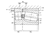
図5は、この発明の他の実施形態に係る自動調心ころ軸受を示している。なお、図2に示した実施形態と同一の参照番号は、同一または相当の要素を示すものであるので、詳しい説明を省略する。図5に示す実施形態では、外輪30を、軸方向に並ぶ2個の分割外輪30A,30Bで構成している。両分割外輪30A,30Bは、自然状態、つまり両分割外輪の軌道面が同じ球面状に位置する状態で、互いの間に隙間dが生じるように設けられている。
FIG. 5 shows a self-aligning roller bearing according to another embodiment of the present invention. Note that the same reference numerals as those in the embodiment shown in FIG. 2 indicate the same or corresponding elements, and detailed description thereof will be omitted. In the embodiment shown in FIG. 5, the
図5に示すように、好ましくは、予圧付与手段41によって、両側の分割外輪30A,30Bの隙間dが狭まるように予圧が付与される。予圧付与手段41として、例えばばね部材や、締め付けねじ等を用いることができる。ばね部材を用いる場合、例えば、円周方向の複数箇所において外輪30Bの端面に接するように圧縮ばねを配置する。予圧付与手段41は、好ましくは、ころ長さの小さい球面ころ12側から予圧を与える。
As shown in FIG. 5, the preload is preferably applied by the
上記のように、外輪30を分割構造にすると、非対称形状の外輪30を容易に製造することができる。また、外輪30に予圧を与えることで、ころ長さの小さな球面ころ12の滑りを積極的に抑制することができる。なお、外輪を分割構造にすることに加えて、内輪20も軸方向に並んだ2個の分割内輪で構成するようにしてもよい。このようにすれば、左右非対称の内輪20の製造が容易になる。
As described above, when the
図6および図7は、図2〜図5に示したような本発明の実施形態に係る複列自動調心ころ軸受が適用された風力発電機の主軸支持構造の一例を示している。主軸支持構造の主要部品を支持するナセル52のケーシング53は、高い位置で、旋回座軸受51を介して支持台50上に水平旋回自在に設置されている。一端にブレード57を保持する主軸56は、ナセル52のケーシング53内で、軸受ハウジング54に組込まれた主軸支持軸受55を介して回転自在に支持されている。主軸56の他端は増速機58に接続され、この増速機58の出力軸が発電機59のロータ軸に結合されている。ナセル52は、旋回用モータ60により、減速機61を介して任意の角度に旋回させられる。
6 and 7 show an example of a main shaft support structure of a wind power generator to which a double row self-aligning roller bearing according to an embodiment of the present invention as shown in FIGS. 2 to 5 is applied. The
図示した実施形態では、主軸支持軸受55は2個並べて設置されているが、1個であってもよい。この主軸支持軸受55として、本発明の実施形態に係る複列自動調心ころ軸受が用いられる。この場合、ブレード57から遠い方の列の球面ころに大きな負荷がかかるので、ころ幅寸法の大きな球面ころを用いる。ブレード57に近い方の列の球面ころには主としてラジアル荷重のみが加わるので、ころ長さの小さな球面ころを用いる。各球面ころの端面は、凸状の球面形状を有している。
In the illustrated embodiment, two main
主軸支持軸受55の内輪は、複列の球面ころの端面に当接する中鍔を有している。中鍔は、ブレード57側に向く一方側面が、球面ころの凸状球面形状に適合する凹状湾曲面を有し、反対側の他方側面が平坦な面を有している。
The inner ring of the main shaft support bearing 55 has a center flange that abuts against the end faces of the double row spherical rollers. The intermediate flange has a concave curved surface that matches the convex spherical shape of the spherical roller on one side surface facing the
以上、図面を参照してこの発明の実施形態を説明したが、この発明は、図示した実施形態のものに限定されない。図示した実施形態に対して、この発明と同一の範囲内において、あるいは均等の範囲内において、種々の修正や変更を加えることが可能である。 As mentioned above, although embodiment of this invention was described with reference to drawings, this invention is not limited to the thing of embodiment shown in figure. Various modifications and changes can be made to the illustrated embodiment within the same range or equivalent range as the present invention.
この発明は、特に左右の列の球面ころに不均等な荷重が作用する複列自動調心ころ軸受およびそのような軸受を備えた風力発電機の主軸支持構造に有利に利用され得る。 The present invention can be advantageously used particularly for a double-row self-aligning roller bearing in which an uneven load acts on the left and right rows of spherical rollers and a main shaft support structure of a wind power generator equipped with such a bearing.
10 複列自動調心ころ軸受、11,12 球面ころ、11a,12a 端面、13 保持器、14 接触だ円、20 内輪、20a,20b 軌道面、21 中鍔、21a,21b 側面、22,23 外鍔、30 外輪、30a 軌道面、31 油溝、32 油孔、40 軸受ハウジング、41 予圧付与手段、50 支持台、51 旋回座軸受、52 ナセル、53 ケーシング、54 軸受ハウジング、55 主軸支持軸受、56 主軸、57 ブレード、58 増速機、59 発電機、60 旋回用モータ、61 減速機。
10 Double Row Spherical Roller Bearing, 11, 12 Spherical Roller, 11a, 12a End Surface, 13 Cage, 14 Contact Ellipse, 20 Inner Ring, 20a, 20b Raceway Surface, 21 Middle, 21a, 21b Side Surface, 22, 23 Outer bush, 30 Outer ring, 30a Raceway surface, 31 Oil groove, 32 Oil hole, 40 Bearing housing, 41 Preload applying means, 50 Support base, 51 Swivel seat bearing, 52 Nacelle, 53 Casing, 54 Bearing housing, 55 Main shaft support bearing 56 spindles, 57 blades, 58 speed increasers, 59 generators, 60 turning motors, 61 speed reducers.
Claims (7)
前記内輪は前記複列の球面ころの端面に当接する中鍔を有し、
前記中鍔に当接する各球面ころの端面は凸状の球面形状を有しており、
前記中鍔は、前記複列の球面ころの端面に当接する両側面のうち、少なくとも一方の側面が平坦な面を有していることを特徴とする、複列自動調心ころ軸受。 In double row spherical roller bearings in which spherical rollers are arranged in double rows between the inner ring and outer ring,
The inner ring has a center abutting against an end surface of the double row spherical roller
The end surface of each spherical roller in contact with the center flange has a convex spherical shape,
The double-row self-aligning roller bearing, wherein at least one side surface of the middle flange has a flat surface among both side surfaces in contact with an end surface of the double-row spherical roller.
その一端が前記ブレードに固定され、ブレードとともに回転する主軸と、
固定部材に組込まれ、前記主軸を回転自在に支持する複列自動調心ころ軸受とを備えた風力発電機の主軸支持構造において、
前記複列自動調心ころ軸受は、内輪と、外輪と、複列の球面ころとを備え、
前記内輪は、前記複列の球面ころの端面に当接する中鍔を有し、
前記中鍔に当接する各球面ころの端面は凸状の球面形状を有しており、
前記中鍔は、その一方側面が、前記球面ころの凸状球面形状に適合する凹状湾曲面を有し、他方側面が平坦な面を有していることを特徴とする、風力発電機の主軸支持構造。 A blade that receives wind,
One end of which is fixed to the blade and rotates with the blade;
In the main shaft support structure of a wind power generator, which is incorporated in a fixed member and includes a double-row self-aligning roller bearing that rotatably supports the main shaft,
The double-row spherical roller bearing includes an inner ring, an outer ring, and a double-row spherical roller,
The inner ring has a center flange that abuts against an end face of the double row spherical roller;
The end surface of each spherical roller in contact with the center flange has a convex spherical shape,
The main shaft of the wind power generator, characterized in that one side surface of the intermediate flange has a concave curved surface that conforms to the convex spherical shape of the spherical roller, and the other side surface has a flat surface. Support structure.
Priority Applications (3)
| Application Number | Priority Date | Filing Date | Title |
|---|---|---|---|
| JP2004290240A JP2006105208A (en) | 2004-10-01 | 2004-10-01 | Double row automatic aligning roller bearing and wind power generator main shaft support device |
| PCT/JP2005/017277 WO2006033320A1 (en) | 2004-09-21 | 2005-09-20 | Double-row self-aligning roller bearing and main shaft support structure for wind-turbine generator |
| US11/663,162 US7922396B2 (en) | 2004-09-21 | 2005-09-20 | Double row self-aligning roller bearing and main shaft support structure of wind power generator |
Applications Claiming Priority (1)
| Application Number | Priority Date | Filing Date | Title |
|---|---|---|---|
| JP2004290240A JP2006105208A (en) | 2004-10-01 | 2004-10-01 | Double row automatic aligning roller bearing and wind power generator main shaft support device |
Publications (1)
| Publication Number | Publication Date |
|---|---|
| JP2006105208A true JP2006105208A (en) | 2006-04-20 |
Family
ID=36375198
Family Applications (1)
| Application Number | Title | Priority Date | Filing Date |
|---|---|---|---|
| JP2004290240A Withdrawn JP2006105208A (en) | 2004-09-21 | 2004-10-01 | Double row automatic aligning roller bearing and wind power generator main shaft support device |
Country Status (1)
| Country | Link |
|---|---|
| JP (1) | JP2006105208A (en) |
Cited By (1)
| Publication number | Priority date | Publication date | Assignee | Title |
|---|---|---|---|---|
| WO2017047506A1 (en) * | 2015-09-17 | 2017-03-23 | Ntn株式会社 | Double-row self-aligning roller bearing |
-
2004
- 2004-10-01 JP JP2004290240A patent/JP2006105208A/en not_active Withdrawn
Cited By (1)
| Publication number | Priority date | Publication date | Assignee | Title |
|---|---|---|---|---|
| WO2017047506A1 (en) * | 2015-09-17 | 2017-03-23 | Ntn株式会社 | Double-row self-aligning roller bearing |
Similar Documents
| Publication | Publication Date | Title |
|---|---|---|
| US7922396B2 (en) | Double row self-aligning roller bearing and main shaft support structure of wind power generator | |
| US10788018B2 (en) | Wind turbine rotor shaft arrangement | |
| JP5412516B2 (en) | Wind power generator | |
| US10385822B2 (en) | Wind turbine rotor shaft arrangement | |
| WO2005050038A1 (en) | Double-row self-aligning roller bearing and device for supporting wind turbine generator main shaft | |
| ES2906786T3 (en) | Composite main bearing arrangement for a wind turbine | |
| JP4522266B2 (en) | Double row roller bearing | |
| JP4699827B2 (en) | Main shaft support structure for tapered roller bearing and wind power generator | |
| WO2017047506A1 (en) | Double-row self-aligning roller bearing | |
| CN113294443A (en) | Bearing device and wind power generation equipment | |
| JP5354849B2 (en) | Wind generator main shaft support structure | |
| WO2018194025A1 (en) | Slewing bearing and processing method thereof | |
| JP2006349032A (en) | Double-row tapered roller bearing and spindle supporting structure of aerogenerator | |
| JP2006177446A (en) | Tapered roller bearing with aligning ring | |
| JP2006105208A (en) | Double row automatic aligning roller bearing and wind power generator main shaft support device | |
| JP2006090346A (en) | Double row automatic aligning roller bearing and main shaft supporting structure of wind power generator | |
| JP4616691B2 (en) | Tapered roller bearing, pin type cage for tapered roller bearing and main shaft support structure of wind power generator | |
| JP2006177447A (en) | Double-row rolling bearing | |
| JP2006090345A (en) | Double row automatic aligning roller bearing and main shaft supporting structure of wind power generator | |
| JP4163596B2 (en) | Double row spherical roller bearing and wind power generator spindle support device | |
| JP2017057951A (en) | Double row self-aligning roller bearing | |
| JP2007132418A (en) | Spindle supporting structure for wind power generator | |
| JP2005164047A (en) | Double row self-aligning roller bearings | |
| JP2006177445A (en) | Double-row automatic aligned roller bearing | |
| JP2005009669A (en) | Self-alignment roller bearing |
Legal Events
| Date | Code | Title | Description |
|---|---|---|---|
| A621 | Written request for application examination |
Free format text: JAPANESE INTERMEDIATE CODE: A621 Effective date: 20070926 |
|
| A761 | Written withdrawal of application |
Free format text: JAPANESE INTERMEDIATE CODE: A761 Effective date: 20080609 |