JP2006105183A - Method of manufacturing hydrodynamic pressure bearing, spindle motor and recording disk driving device - Google Patents
Method of manufacturing hydrodynamic pressure bearing, spindle motor and recording disk driving device Download PDFInfo
- Publication number
- JP2006105183A JP2006105183A JP2004289561A JP2004289561A JP2006105183A JP 2006105183 A JP2006105183 A JP 2006105183A JP 2004289561 A JP2004289561 A JP 2004289561A JP 2004289561 A JP2004289561 A JP 2004289561A JP 2006105183 A JP2006105183 A JP 2006105183A
- Authority
- JP
- Japan
- Prior art keywords
- peripheral surface
- sleeve
- bearing
- dynamic pressure
- bearing housing
- Prior art date
- Legal status (The legal status is an assumption and is not a legal conclusion. Google has not performed a legal analysis and makes no representation as to the accuracy of the status listed.)
- Withdrawn
Links
Images


Abstract
Description
本発明は、軸受、特に、流体動圧軸受に関する。また別の本発明は、流体動圧軸受を用いたスピンドルモータ、記録ディスク駆動装置および流体動圧軸受の製造方法に関する。 The present invention relates to a bearing, and more particularly to a fluid dynamic pressure bearing. Further, the present invention relates to a spindle motor using a fluid dynamic pressure bearing, a recording disk drive device, and a method of manufacturing a fluid dynamic pressure bearing.
従来、ハードディスクなどに用いられる小型の駆動装置には、高速化及び低振動化を目的として流体動圧軸受が採用されている。流体動圧軸受は、軸と軸受部材との間に軸受流体を充填し、軸と軸受部材とが相対回転する際に発生する動圧により軸を軸受部材と非接触状態で支持するものである。このような流体動圧軸受は、軸を非接触状態で支持しているため、従来のボールベアリングなどと比べて低振動、低騒音となり、回転精度が向上し回転の高速化が可能となる。
このような流体動圧軸受は、機器を構成する部材への取り付けのためユニット化されている。例えば、スリーブが軸受ハウジングと呼ばれる筒状またはカップ状の部材に内嵌され、軸受ハウジングを介して、機器を構成する部材へと取り付けられるといった構造が知られている(例えば、特許文献1参照。)。さらに詳しくは、この流体動圧軸受は、外周面に動圧発生用溝が形成された円柱状のシャフトと、シャフトの外周面と径方向微少間隙を介して対向する内周面を有する円筒状のスリーブと、スリーブの外周面と当接する内周面を有しスリーブを内嵌して固定する軸受ハウジングとを備えている。この流体動圧軸受では、シャフトとスリーブおよび軸受ハウジングとが相対回転することにより、シャフトの外周面とスリーブの内周面との径方向微少間隙に動圧が発生し、ラジアル軸受を構成する。
2. Description of the Related Art Conventionally, fluid dynamic pressure bearings have been employed in small drive devices used for hard disks and the like for the purpose of speeding up and reducing vibration. A fluid dynamic pressure bearing is one in which a bearing fluid is filled between a shaft and a bearing member, and the shaft is supported in a non-contact state with the bearing member by dynamic pressure generated when the shaft and the bearing member rotate relative to each other. . Since such a fluid dynamic pressure bearing supports the shaft in a non-contact state, the vibration and noise are reduced as compared with a conventional ball bearing and the like, the rotation accuracy is improved, and the rotation speed can be increased.
Such a fluid dynamic pressure bearing is unitized for attachment to a member constituting the device. For example, a structure is known in which a sleeve is fitted into a cylindrical or cup-shaped member called a bearing housing, and is attached to a member constituting a device via the bearing housing (see, for example, Patent Document 1). ). More specifically, this fluid dynamic pressure bearing is a cylindrical shaft having a cylindrical shaft having a dynamic pressure generating groove formed on the outer peripheral surface, and an inner peripheral surface facing the outer peripheral surface of the shaft with a small radial gap. And a bearing housing having an inner peripheral surface that comes into contact with the outer peripheral surface of the sleeve and in which the sleeve is fitted and fixed. In this fluid dynamic pressure bearing, when the shaft, the sleeve, and the bearing housing rotate relative to each other, a dynamic pressure is generated in a small radial gap between the outer peripheral surface of the shaft and the inner peripheral surface of the sleeve, thereby constituting a radial bearing.
また、カップ状の軸受ハウジングを備える流体動圧軸受として、軸受ハウジングの軸方向端面をスラスト軸受面の一方の面とする構造が知られている。すなわち、この構造では、円筒状の外周面を有するシャフトと、シャフトの外周面と径方向微少間隙を介して対向する内周面を有する円筒状のスリーブと、スリーブの環状の外周面をその内周面に対向させて内嵌するカップ状の軸受ハウジングとを備えている。さらに、この構造では、シャフトの外周面とスリーブの内周面とその間の径方向微少間隙に保持される動圧発生流体とによりラジアル軸受が構成され、軸受ハウジングの軸方向端面とシャフトに固定されたシャフト基部の軸方向に向く平坦面とその間の軸方向微少間隙に保持される動圧発生流体とによりスラスト軸受が構成される。
このような構成の流体動圧軸受では、高い回転精度を得るために、ラジアル軸受とスラスト軸受との直角精度を高めることが求められている。
In the fluid dynamic bearing having such a configuration, in order to obtain high rotational accuracy, it is required to improve the right-angle accuracy between the radial bearing and the thrust bearing.
上記の要求に対応するためには、スリーブと軸受ハウジングとの部品精度を向上させることが考えられる。すなわち、スリーブの外周面の加工精度と軸受ハウジングの内周面および軸方向端面の加工精度とを向上させることが考えられる。しかし、低コスト化の要求があるため、このような部品精度を向上させる加工を採用することは難しい。
そこで、本発明では、より簡易かつ低コストに、ラジアル軸受とスラスト軸受との直角精度を高めた流体動圧軸受を提供することを課題とする。さらに、別の本発明では、流体動圧軸受を用いたスピンドルモータ、記録ディスク駆動装置および流体動圧軸受の製造方法を提供することを課題とする。
In order to meet the above requirements, it is conceivable to improve the component accuracy of the sleeve and the bearing housing. That is, it is conceivable to improve the processing accuracy of the outer peripheral surface of the sleeve and the processing accuracy of the inner peripheral surface and the axial end surface of the bearing housing. However, since there is a demand for cost reduction, it is difficult to employ such processing that improves the accuracy of parts.
Therefore, an object of the present invention is to provide a fluid dynamic pressure bearing with improved accuracy in the right angle between the radial bearing and the thrust bearing at a simpler and lower cost. Another object of the present invention is to provide a spindle motor using a fluid dynamic pressure bearing, a recording disk drive device, and a method of manufacturing a fluid dynamic pressure bearing.
請求項1に記載の流体動圧軸受は、シャフト基部と、シャフトと、スリーブと、軸受ハウジングとを備えている。シャフトは、シャフト基部の一端側に立設され、円筒状の外周面を有する。スリーブは、シャフトの外周面と径方向微少間隙を介して対向する内周面を有する。軸受ハウジングは、スリーブを内嵌する。軸受ハウジングの軸方向他端には軸方向端面が形成される。軸方向端面は、シャフト基部の軸方向一端側に形成された平坦面と軸方向微少間隙を介して対向する。シャフトの外周面と、スリーブの内周面と、その間の径方向微少間隙に保持される動圧発生流体とによってラジアル軸受が構成されている。シャフト基部の平坦面と、軸受ハウジングの軸方向端面と、その間の軸方向微少間隙に保持される動圧発生流体とによってスラスト軸受が構成されている。スリーブの外周面あるいは軸受ハウジングの内周面のいずれか一方には、他方に向けて突出するとともに、その突出量が軸方向両側に向けて滑らかに減少する突出部が形成されている。
ここで、軸受ハウジングとは、例えば、流体動圧軸受を備える機器の回転部材あるいは静止部材に対して、スリーブを取り付けるための部材である。また、スリーブの外周面あるいは軸受ハウジングの内周面のいずれか一方には、他方に向けて突出する突出部が形成されている。これにより、スリーブの外周面は、例えば、略俵状に形成され、軸受ハウジングの内周面は、例えば、略鼓状に形成される。
A fluid dynamic pressure bearing according to a first aspect includes a shaft base, a shaft, a sleeve, and a bearing housing. The shaft is erected on one end side of the shaft base and has a cylindrical outer peripheral surface. The sleeve has an inner peripheral surface that opposes the outer peripheral surface of the shaft with a small radial gap. The bearing housing has a sleeve fitted therein. An axial end surface is formed at the other axial end of the bearing housing. The axial end surface is opposed to a flat surface formed on one axial end side of the shaft base through an axial minute gap. A radial bearing is constituted by the outer peripheral surface of the shaft, the inner peripheral surface of the sleeve, and the dynamic pressure generating fluid held in the minute radial gap therebetween. A thrust bearing is constituted by the flat surface of the shaft base, the axial end surface of the bearing housing, and the dynamic pressure generating fluid held in the minute axial gap therebetween. Either one of the outer peripheral surface of the sleeve or the inner peripheral surface of the bearing housing is formed with a protruding portion that protrudes toward the other and whose protruding amount smoothly decreases toward both axial sides.
Here, the bearing housing is, for example, a member for attaching a sleeve to a rotating member or a stationary member of a device including a fluid dynamic pressure bearing. In addition, a protruding portion that protrudes toward the other is formed on either the outer peripheral surface of the sleeve or the inner peripheral surface of the bearing housing. Thereby, the outer peripheral surface of the sleeve is formed in a substantially bowl shape, for example, and the inner peripheral surface of the bearing housing is formed in a substantially drum shape, for example.
本発明の流体動圧軸受では、スリーブの外周面と軸受ハウジングの内周面とは突出部においてお互いに接している。突出部は、スリーブの外周面あるいは軸受ハウジングの内周面のいずれか一方に形成され、他方に向けて突出するとともに、その突出量が軸方向両側に向けて滑らかに減少する。このため、突出部を当接させた状態でスリーブと軸受ハウジングとを揺動させ、ラジアル軸受を構成するスリーブの内周面とスラスト軸受を構成する軸受ハウジングの軸方向端面との直角精度を調整することが可能となる。すなわち、スリーブの外周面と軸受ハウジングの内周面との加工精度を高めることなく、ラジアル軸受とスラスト軸受との直角精度を高めた流体動圧軸受を提供することが可能となる。
請求項2に記載の流体動圧軸受は、請求項1に記載の流体動圧軸受であって、突出部は、スリーブの外周面あるいは軸受ハウジングの内周面のいずれか一方において、周方向に連続して形成されている。
本発明の流体動圧軸受では、スリーブの外周面の軸方向1箇所において、外径の大きい部分が形成される、あるいは軸受ハウジングの内周面の軸方向1箇所において、内径の小さい部分が形成される。
請求項3に記載の流体動圧軸受は、請求項1または2に記載の流体動圧軸受であって、軸受ハウジングは、プレス加工により形成されている。
In the fluid dynamic pressure bearing of the present invention, the outer peripheral surface of the sleeve and the inner peripheral surface of the bearing housing are in contact with each other at the protruding portion. The protrusion is formed on either the outer peripheral surface of the sleeve or the inner peripheral surface of the bearing housing, protrudes toward the other, and the amount of protrusion smoothly decreases toward both axial sides. For this reason, the sleeve and the bearing housing are swung with the protrusions in contact with each other, and the right angle accuracy between the inner peripheral surface of the sleeve constituting the radial bearing and the axial end surface of the bearing housing constituting the thrust bearing is adjusted. It becomes possible to do. That is, it is possible to provide a fluid dynamic pressure bearing in which the accuracy of the right angle between the radial bearing and the thrust bearing is improved without increasing the processing accuracy of the outer peripheral surface of the sleeve and the inner peripheral surface of the bearing housing.
A fluid dynamic pressure bearing according to a second aspect is the fluid dynamic pressure bearing according to the first aspect, wherein the projecting portion extends in the circumferential direction on either the outer peripheral surface of the sleeve or the inner peripheral surface of the bearing housing. It is formed continuously.
In the fluid dynamic pressure bearing of the present invention, a portion having a large outer diameter is formed at one axial position on the outer peripheral surface of the sleeve, or a portion having a small inner diameter is formed at one axial position on the inner peripheral surface of the bearing housing. Is done.
A fluid dynamic pressure bearing according to a third aspect is the fluid dynamic pressure bearing according to the first or second aspect, wherein the bearing housing is formed by pressing.
プレス加工の特徴として、低コストであるが加工精度を向上させることが難しい点が上げられる。このため、従来の流体動圧軸受では、軸受ハウジングにプレス加工を用いつつ、スリーブの内周面と軸受ハウジングの軸方向端面とに高い直角精度を得ることは難しい。
本発明の流体動圧軸受では、プレス加工の精度に依存せずスリーブの内周面と軸受ハウジングの軸方向端面とに高い直角精度を得ることが可能となる。このため、より低コストにラジアル軸受とスラスト軸受との直角精度を高めた流体動圧軸受を提供することが可能となる。
請求項4に記載の流体動圧軸受は、請求項1または2に記載の流体動圧軸受であって、軸受ハウジングは、樹脂により形成されている。
樹脂により形成される部材の加工精度は、金型の精度に影響されやすく、高い加工精度を得ることが難しい。
本発明の流体動圧軸受では、樹脂により形成された軸受ハウジングの加工精度に依存せずスリーブの内周面と軸受ハウジングの軸方向端面とに高い直角精度を得ることが可能となる。このため、より低コストにラジアル軸受とスラスト軸受との直角精度を高めた流体動圧軸受を提供することが可能となる。
A feature of press working is that it is difficult to improve machining accuracy at a low cost. For this reason, in the conventional fluid dynamic pressure bearing, it is difficult to obtain a high right-angle accuracy between the inner peripheral surface of the sleeve and the end surface in the axial direction of the bearing housing while using press working for the bearing housing.
In the fluid dynamic pressure bearing of the present invention, high perpendicular accuracy can be obtained between the inner peripheral surface of the sleeve and the axial end surface of the bearing housing without depending on the accuracy of the press working. For this reason, it is possible to provide a fluid dynamic pressure bearing with higher accuracy in the right angle between the radial bearing and the thrust bearing at a lower cost.
A fluid dynamic pressure bearing according to a fourth aspect is the fluid dynamic pressure bearing according to the first or second aspect, wherein the bearing housing is formed of a resin.
The processing accuracy of the member formed of resin is easily affected by the accuracy of the mold, and it is difficult to obtain high processing accuracy.
In the fluid dynamic pressure bearing of the present invention, high perpendicular accuracy can be obtained between the inner peripheral surface of the sleeve and the axial end surface of the bearing housing without depending on the processing accuracy of the bearing housing formed of resin. For this reason, it is possible to provide a fluid dynamic pressure bearing with higher accuracy in the right angle between the radial bearing and the thrust bearing at a lower cost.
請求項5に記載の流体動圧軸受は、請求項1〜4のいずれかに記載の流体動圧軸受であって、スリーブは、焼結金属により形成されている。
スリーブを金属粉末を焼結して形成すると、多孔質であり潤滑油をスリーブ内に保持することができるため、軸受部材に適している。一方、寸法の管理が困難であるために、サイジングと呼ばれる寸法合わせの工程が必要である。
本発明の流体動圧軸受では、例えば、スリーブの外周面に突出部が形成される場合であっても、上記サイジングの工程において突出部の加工を行うことが可能である。このため、作業性の低下やコストの上昇などを伴わずに突出部の加工を行うことが可能となる。
請求項6に記載の流体動圧軸受は、請求項1〜5のいずれかに記載の流体動圧軸受であって、スリーブと軸受ハウジングとは、スリーブの外周面と軸受ハウジングの内周面とにより形成される径方向間隙に接着剤が充填されることにより、固定されている。
スリーブの外周面と軸受ハウジングの内周面とにより形成される径方向間隙は、突出部から軸方向両端に向かって拡がるように形成されている。
本発明の流体動圧軸受では、軸方向両端に向かって拡がる径方向間隙に接着剤が充填されるため、径方向間隙では、充分な量の接着剤を保持することが可能となる。これにより、スリーブと軸受ハウジングとの接着による締結強度を高めることが可能となる。
A fluid dynamic pressure bearing according to a fifth aspect is the fluid dynamic pressure bearing according to any one of the first to fourth aspects, wherein the sleeve is formed of a sintered metal.
When the sleeve is formed by sintering metal powder, the sleeve is porous and lubricating oil can be held in the sleeve, which is suitable for a bearing member. On the other hand, since it is difficult to manage dimensions, a dimension matching process called sizing is required.
In the fluid dynamic pressure bearing of the present invention, for example, even when a protrusion is formed on the outer peripheral surface of the sleeve, it is possible to process the protrusion in the sizing step. For this reason, it becomes possible to process a protrusion part, without the fall of workability | operativity, a raise of cost, etc.
A fluid dynamic pressure bearing according to a sixth aspect is the fluid dynamic pressure bearing according to any one of the first to fifth aspects, wherein the sleeve and the bearing housing include an outer peripheral surface of the sleeve and an inner peripheral surface of the bearing housing. It is fixed by filling the radial gap formed by the adhesive with an adhesive.
A radial gap formed by the outer peripheral surface of the sleeve and the inner peripheral surface of the bearing housing is formed so as to expand from the protruding portion toward both axial ends.
In the fluid dynamic pressure bearing of the present invention, since the adhesive is filled in the radial gap that expands toward both ends in the axial direction, a sufficient amount of adhesive can be held in the radial gap. This makes it possible to increase the fastening strength due to the adhesion between the sleeve and the bearing housing.
請求項7に記載の流体動圧軸受は、請求項1〜6のいずれかに記載の流体動圧軸受であって、シャフト基部の平坦面は、シャフトに直交する。
ここで、シャフト基部とは、例えば、流体動圧軸受を搭載するスピンドルモータの回転部材を構成するロータハブなどである。
本発明の流体動圧軸受では、シャフトの外周面とスリーブの内周面との間にラジアル軸受が形成され、軸受ハウジングの軸方向端面とシャフト基部の平坦面との間にスラスト軸受が形成される。ラジアル軸受を構成するスリーブの内周面とスラスト軸受を構成する軸受ハウジングの軸方向端面との直角精度は、突出部の作用により調整可能である。すなわち、ラジアル軸受とスラスト軸受との直角精度が調整可能となる。
請求項8に記載のスピンドルモータは、請求項1〜7のいずれかに記載の流体動圧軸受と、シャフトあるいはスリーブのいずれかと一体的に回転するロータマグネットと、ロータマグネットに対向して配置されるステータとを備えている。
本発明のスピンドルモータでは、請求項1〜7のいずれかに記載の流体動圧軸受と同様の効果を得ることが可能となり、より簡易かつ低コストに、ラジアル軸受とスラスト軸受との直角精度を高めた流体動圧軸受を備えるスピンドルモータを提供することが可能となる。
A fluid dynamic pressure bearing according to a seventh aspect is the fluid dynamic pressure bearing according to any one of the first to sixth aspects, wherein the flat surface of the shaft base is orthogonal to the shaft.
Here, the shaft base is, for example, a rotor hub that constitutes a rotating member of a spindle motor on which a fluid dynamic pressure bearing is mounted.
In the fluid dynamic pressure bearing of the present invention, a radial bearing is formed between the outer peripheral surface of the shaft and the inner peripheral surface of the sleeve, and a thrust bearing is formed between the axial end surface of the bearing housing and the flat surface of the shaft base. The The right angle accuracy between the inner peripheral surface of the sleeve constituting the radial bearing and the axial end surface of the bearing housing constituting the thrust bearing can be adjusted by the action of the protruding portion. That is, the right angle accuracy between the radial bearing and the thrust bearing can be adjusted.
A spindle motor according to an eighth aspect is disposed to face the rotor magnet, the fluid dynamic pressure bearing according to any one of the first to seventh aspects, a rotor magnet that rotates integrally with either the shaft or the sleeve, and the rotor magnet. And a stator.
In the spindle motor of the present invention, it is possible to obtain the same effect as that of the fluid dynamic pressure bearing according to any one of claims 1 to 7, and the right angle accuracy between the radial bearing and the thrust bearing can be achieved more simply and at low cost. It is possible to provide a spindle motor including an enhanced fluid dynamic pressure bearing.
請求項9に記載の記録ディスク装置は、ハウジングと、ハウジングに固定されるスピンドルモータであって、情報を記録できるディスク状記録媒体を回転させる請求項7に記載のスピンドルモータと、記録媒体の所要の位置に情報を書き込むまたは読み出すための情報アクセス手段とを備えている。
本発明の記録ディスク装置では、請求項8に記載のスピンドルモータと同様の効果を得ることが可能となり、より簡易かつ低コストに、ラジアル軸受とスラスト軸受との直角精度を高めた流体動圧軸受を備える記録ディスク装置を提供することが可能となる。
請求項10に記載の流体動圧軸受の製造方法は、円筒状の外周面を有するシャフトと、シャフトの外周面と径方向微少間隙を介して対向する内周面を有するスリーブと、スリーブを内嵌する軸受ハウジングとを備える流体動圧軸受の製造方法であって、嵌合工程と、接着剤塗布工程と、直角精度調整工程とを備えている。嵌合工程は、スリーブの外周面あるいは軸受ハウジングの内周面のいずれか一方に形成され、他方に向けて突出するとともに、その突出量が軸方向両側に向けて滑らかに減少する突出部を、他方と接触させて嵌合する。接着剤塗布工程は、スリーブの外周面と軸受ハウジングの内周面との少なくとも一方に接着剤を塗布する。直角精度調整工程は、スリーブの内周面と軸受ハウジングの軸方向端面との直角精度を調整する。
The recording disk device according to claim 9 is a housing and a spindle motor fixed to the housing, and rotates a disk-shaped recording medium on which information can be recorded. And an information access means for writing or reading information at the position.
In the recording disk device of the present invention, it is possible to obtain the same effect as that of the spindle motor according to claim 8, and a fluid dynamic pressure bearing in which the right angle accuracy between the radial bearing and the thrust bearing is improved more easily and at a lower cost. It is possible to provide a recording disk device comprising
The method of manufacturing a fluid dynamic pressure bearing according to
本発明の製造方法により、流体動圧軸受を構成する部材の加工精度の向上によってではなく構造的な改善によってスリーブの内周面と軸受ハウジングの軸方向端面との直角精度を調整することが可能となる。このため、より簡易かつ低コストに、ラジアル軸受とスラスト軸受との直角精度を高めた流体動圧軸受を製造することが可能となる。
請求項11に記載の流体動圧軸受の製造方法は、請求項10に記載の流体動圧軸受の製造方法であって、直角精度調整工程は、スリーブの内周面と軸受ハウジングの軸方向端面との直角精度を治具を用いて調整する工程と、接着剤を硬化させスリーブと軸受ハウジングとを固定する工程とを含む。
本発明の製造方法により、部材の加工精度の向上によってではなく治具の精度を高めることによって、流体動圧軸受の直角精度を高めることができる。このため、より簡易かつ低コストに、ラジアル軸受とスラスト軸受との直角精度を高めた流体動圧軸受を製造することが可能となる。さらに、治具によって直角精度の調整を行うため、製造された流体動圧軸受における直角精度のばらつきを抑えることが可能となる。
With the manufacturing method of the present invention, it is possible to adjust the right angle accuracy between the inner peripheral surface of the sleeve and the axial end surface of the bearing housing not by improving the processing accuracy of the members constituting the fluid dynamic pressure bearing but by improving the structure. It becomes. For this reason, it becomes possible to manufacture a fluid dynamic pressure bearing with improved right-angle accuracy between the radial bearing and the thrust bearing at a simpler and lower cost.
The fluid dynamic pressure bearing manufacturing method according to
With the manufacturing method of the present invention, it is possible to increase the right angle accuracy of the fluid dynamic pressure bearing by increasing the accuracy of the jig, not by improving the processing accuracy of the member. For this reason, it becomes possible to manufacture a fluid dynamic pressure bearing with improved right-angle accuracy between the radial bearing and the thrust bearing at a simpler and lower cost. Furthermore, since the right angle accuracy is adjusted by the jig, it is possible to suppress the variation in the right angle accuracy in the manufactured fluid dynamic pressure bearing.
本発明により、より簡易かつ低コストに、ラジアル軸受とスラスト軸受との直角精度を高めた流体動圧軸受を提供することが可能となる。さらに、別の本発明では、流体動圧軸受を用いたスピンドルモータ、記録ディスク駆動装置および流体動圧軸受の製造方法を提供することが可能となる。 According to the present invention, it is possible to provide a fluid dynamic pressure bearing in which the accuracy of the right angle between the radial bearing and the thrust bearing is improved more simply and at low cost. Furthermore, according to another aspect of the present invention, it is possible to provide a spindle motor using a fluid dynamic pressure bearing, a recording disk drive device, and a method of manufacturing a fluid dynamic pressure bearing.
[1]流体動圧軸受の構成
〈1〉全体構成
図1を用いて、本発明の実施形態としての流体動圧軸受10について説明する。なお、図面を用いた説明では、便宜上図面の上下方向を軸線上下方向とするが、これは、実際の取り付け状態を限定するものではない。
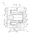
図1に示す流体動圧軸受10は、機器のハウジング11に設けられたハブ12に固定される軸受ハウジング17と、軸受ハウジング17に内嵌されるスリーブ16と、スリーブ16に対して回転自在に支持されるシャフト13とから主に構成されている。ここで、機器とは、例えば、ハードディスクなどの記録ディスクを駆動させるためのスピンドルモータを備えるハードディスク装置などである。
シャフト13は、下部13aに対して小径の上部13bを有するほぼ円柱状の部材である。シャフト13は、スピンドルモータのロータハブ14の回転中心に設けられた中心孔14aにおいて軸方向下向きに立設されている。より詳しくは、後述するロータハブ14の平坦面14bとシャフト13の軸とが直交するように立設されている。
スリーブ16は、シャフト13の円筒状の下部外周面13cと対向する内周面16aを備えるほぼ円筒状の部材である。スリーブ16は、環状の内周面16aをシャフト13の下部外周面13cと径方向微少間隙18を介して対向させることにより、シャフト13を回転可能に支持している。さらに、スリーブ16は、軸受ハウジング17の内部に嵌め合わされるとともに接着されており、円筒状の外周面16bと軸受ハウジング17の内周面17aとが当接した状態で固定されている。このとき、スリーブ16と軸受ハウジング17とは、環状の軸方向上端面16cの軸線方向位置と軸受ハウジング17の環状面21c(後述)の軸線方向位置とをほぼ一致させて固定されている。
[1] Configuration of Fluid Dynamic Pressure Bearing <1> Overall Configuration A fluid dynamic pressure bearing 10 as an embodiment of the present invention will be described with reference to FIG. In the description using the drawings, the vertical direction of the drawing is defined as the vertical direction of the axis for convenience, but this does not limit the actual mounting state.
A fluid dynamic pressure bearing 10 shown in FIG. 1 has a bearing
The
The
軸受ハウジング17は、カップ形状の部材であり、内周面17aを有する側部19と、側部19の下端から径方向に連続する円盤状の底部20とから構成されている。
側部19の下部外周面19aは、軸方向に延びる筒状に形成されており、ハウジング11のハブ12に固定されている。
側部19の上部には、下部外周面19aよりも大径の上部外周面21aを有する縁部21が形成されている。上部外周面21aは、軸線方向上側に向けて径が大きくなる傾斜面により形成されており、その下端においてもなお下部外周面19aよりも大径である。これにより、縁部21の下端には、上部外周面21aの下端縁から下部外周面19aの上端縁まで、径方向に向けて延びる環状の下端面21bが形成されている。
また、縁部21の軸線方向上側を向く環状面21cは、ロータハブ14の環状の平坦面14bと軸方向微少間隙26を介して対向する。ここで、平坦面14bとは、ロータハブ14の中心孔14aの下縁から環状突起部23までにわたって径方向に拡がる環状面である。またここで、環状突起部23とは、ロータハブ14において、中心孔14aと同心に形成された軸線方向下側に向かう環状の突起部である。
この環状突起部23の下部に形成される段部23bには、リング状の抜け止め25が取り付けられている。リング状の抜け止め25は、環状の軸線方向上端面の内周側を軸受ハウジング17の下端面21bと対向させており、ロータハブ14およびシャフト13の軸線方向上側への移動を制限する。
The bearing
A lower outer
An
Further, the
A ring-shaped retaining
軸受ハウジング17の内周面17aには、スリーブ16に向けて突出するとともに、その突出量が軸方向両側に向けて滑らかに減少する突出部15が形成されている。すなわち、内周面17aは、軸線を含む断面が径方向内方に向けて凸となる凸曲面から構成されている。さらに言い換えれば、内周面17aは、上端部および下端部の径が中央部の径よりも大きく、それらの径が軸方向に連続的に変化する略鼓状に形成されている。
内周面17aは、最小の径を有する中央部の径がスリーブ16の外周面16bの径とほぼ同じになるように形成されている。これにより、軸受ハウジング17をスリーブ16に嵌め合わせた場合にそれぞれの軸線をほぼ一致させることができる(同軸度を得ることができる。)。
内周面17aの上端部および下端部は、スリーブ16の外周面16bとの間に間隙を有しているが、この間隙には、接着剤24が充填されている。この接着剤24により、スリーブ16と軸受ハウジング17とは固定されている。
〈2〉動圧発生機構
流体動圧軸受10は、動圧発生部として、ラジアル軸受部35と、スラスト軸受部36とを有している。各軸受部において対向する面により形成される間隙とスリーブ16の外周面16bの数箇所においてスリーブ16の軸方向上下を連通するように形成される連通孔27とには、潤滑油38が満たされている(空気によって遮断された部分を有していない。)。潤滑油38は、環状突起部23の内周面23aと軸受ハウジング17の上部外周面21aとの間に形成される表面張力シール部39のみにて、界面を形成して外気に通じている。これにより、流体動圧軸受10では、いわゆるフルフィル構造が実現されている。
On the inner
The inner
The upper end portion and the lower end portion of the inner
<2> Dynamic Pressure Generating Mechanism The fluid dynamic pressure bearing 10 includes a
なお、本実施形態では、フルフィル構造が実現されているとしたが、軸受ハウジング17の下端が開口し、上下に界面を作るような構造であっても本発明を適用可能である。さらに、潤滑油38が軸受部分(ラジアル軸受部35およびスラスト軸受部36)にのみ保持される構造の動圧軸受(パーシャルフィル構造)についても、本発明を適用可能である。
以下、各軸受部の構造を説明する。なお、図1では、後述する各動圧発生用溝を断面上に記入しているが、実際には各部材の表面に形成されている。
(1)ラジアル軸受部
ラジアル軸受部35は、スリーブ16の内周面16aと、内周面16aに対向するシャフト13の下部外周面13cと、その間の潤滑油38とにより構成されている。
スリーブ16の内周面16aには、シャフト13の回転に伴い潤滑油38中に動圧を発生するためのヘリングボーン状のラジアル動圧発生用溝41が軸方向2箇所に形成されている。ここで、ラジアル動圧発生用溝41は、回転方向に並んだ複数の溝であり、各溝は回転方向に対して相反する方向に傾斜する一対のスパイラル溝を連結してなる略「く」の字状の溝である。
In this embodiment, the full-fill structure is realized. However, the present invention can be applied even to a structure in which the lower end of the bearing
Hereinafter, the structure of each bearing part will be described. In FIG. 1, each dynamic pressure generating groove, which will be described later, is shown on the cross section, but it is actually formed on the surface of each member.
(1) Radial bearing part The
On the inner
ラジアル軸受部35では、ラジアル動圧発生用溝41は、バランス形状に形成されており、ラジアル軸受部35における流体動圧は、回転方向に対して相反する方向に傾斜する一対のスパイラル溝の連結部において極大となっている。
なお、軸受内の負圧の発生を防止するために、軸方向2箇所に形成されたラジアル動圧発生用溝41のうち軸方向上側のラジアル動圧発生用溝41は、軸方向下側に向けて潤滑油38を流動させる形状のヘリングボーンであってもよい。
なお、ラジアル動圧発生用溝41は、シャフト13の下部外周面13cに形成されていてもよい。
(2)スラスト軸受部
スラスト軸受部36は、軸受ハウジング17の環状面21cおよびスリーブ16の軸方向上端面16cと、ロータハブ14の平坦面14bと、その間の潤滑油38とにより構成されている。
軸受ハウジング17の上部外周面21aには、ロータハブ14の回転に伴い潤滑油38中に動圧を発生するためのスパイラル状のスラスト動圧発生用溝43が形成されており、回転時にロータハブ14を軸線方向上方に支持する。
In the
In order to prevent the generation of negative pressure in the bearing, the radial dynamic
The radial dynamic
(2) Thrust bearing portion The
A spiral thrust dynamic
また、スパイラル状のスラスト動圧発生用溝43は、スラスト軸受部36の潤滑油38を半径方向内側に流動させるように形成されている。これにより、軸受内の負圧の発生が防止される。
なお、スラスト動圧発生用溝43は、潤滑油38を半径方向内側に流動させるように形成されるアンバランスのヘリングボーン形状であってもよい。
なお、スラスト動圧発生用溝43は、平坦面14bに形成されていてもよい。
(3)表面張力シール部
表面張力シール部39は、スラスト軸受部36からの潤滑油38の漏れを防止するための構造であり、環状突起部23の内周面23aと軸受ハウジング17の上部外周面21aとの間に形成される。表面張力シール部39では、流体動圧軸受10に保持された潤滑油38の表面張力と外気の空気圧等とが釣り合うことにより、潤滑油38が流体動圧軸受10の外部に移動するのが抑制される。また、潤滑油38と外気との接触を最小に抑えることができ、潤滑油38の蒸発を抑えることが可能となる。
[2]製造方法
図1をさらに参照して、流体動圧軸受10の製造方法について説明する。
The spiral thrust dynamic
The thrust dynamic
The thrust dynamic
(3) Surface tension seal portion The surface
[2] Manufacturing Method With reference to FIG. 1 further, a manufacturing method of the fluid
第1の工程では、流体動圧軸受10を構成する各部材が形成される。
スリーブ16は、金属粉末を焼結成形することにより形成された焼結含油多孔質体である。スリーブ16の内周面16aには、ラジアル動圧発生用溝41がプレス成形される。シャフト13には、ステンレス鋼を表面処理した金属の切削品が用いられる。なお、シャフト13およびスリーブ16は、セラミックにより形成されていてもよい。
軸受ハウジング17の概形は、金属板材をプレス成形することによりすることにより形成される。また同時に、軸受ハウジング17の環状面21cには、スラスト動圧発生用溝43がプレス成形される。なお、軸受ハウジング17は、金属を切削することにより、あるいは樹脂を射出成形することにより形成されてもよい。
第2の工程では、スリーブ16と軸受ハウジング17とが組み付けられる。この際、スリーブ16の外周面16bと軸受ハウジング17の内周面17aの突出部15とが当接した状態で嵌め合わされる。
第3の工程では、スリーブ16の外周面16bと軸受ハウジング17の内周面17aとに挟まれる間隙に接着剤が充填される。
第4の工程では、接着剤硬化前にスリーブ16の内周面16aと軸受ハウジング17の環状面21cとの直角度が治具を用いて調整される。軸受ハウジング17の内周面17aは、軸方向の中央部を径方向内側に突出させるように形成されており、スリーブ16に対して軸受ハウジング17を揺動させることが可能である。これにより、スリーブ16の内周面16aと軸受ハウジング17の環状面21cとの直角度を調整することが可能となる。
In the first step, each member constituting the fluid dynamic pressure bearing 10 is formed.
The
The general shape of the bearing
In the second step, the
In the third step, an adhesive is filled in the gap between the outer
In the fourth step, the perpendicularity between the inner
第5の工程では、流体動圧軸受10を構成する各部材が組み付けられる。まず、ロータハブ14の中心孔14aにシャフト13の上部13bが固定される。さらに、第2〜第4の工程により組み付けられたスリーブ16と軸受ハウジング17とが、スリーブ16の内周面16aをシャフト13の下部外周面13cに対向させて取り付けられる。またさらに、リング状の抜け止め25が段部23bに取り付けられる。この際、径方向微少間隙18、軸方向微少間隙26および表面張力シール部39には潤滑油38が注入されている。
なお、第2〜第4の工程の順序は、上記した順序に限定されるものではない。例えば、スリーブ16の外周面16bと軸受ハウジング17の内周面17aとに接着剤を塗布した後(第3の工程)、スリーブ16と軸受ハウジング17とを組み付けてもよい(第2の工程)。また、第4の工程は、接着剤硬化前に行われればよく、角度調整後(第4の工程)にスリーブ16の外周面16bと軸受ハウジング17の内周面17aとの間隙に接着剤が充填されてもよい。
[3]スピンドルモータ及びハードディスク装置
〈1〉スピンドルモータの構成
図2を用いて、流体動圧軸受10を備えるスピンドルモータ52の縦断面概略図を示す。
In the fifth step, each member constituting the fluid dynamic pressure bearing 10 is assembled. First, the
Note that the order of the second to fourth steps is not limited to the order described above. For example, after the adhesive is applied to the outer
[3] Spindle Motor and Hard Disk Device <1> Configuration of Spindle Motor FIG. 2 is a schematic vertical sectional view of a
スピンドルモータ52は、流体動圧軸受10と、ロータハブ14を介してシャフト13に固定されて一体的に回転するロータマグネット62と、ロータマグネット62に対向して配置されるステータ63とから主に構成されている。
流体動圧軸受10の構成は、図1を用いて説明したため、ここでは説明を省略する。流体動圧軸受10は、ハウジング11のハブ12に形成された孔12aに軸受ハウジング17の下部外周面19aを固定して取り付けられている。
ロータハブ14は、シャフト13の上部13bを固定し、外周部に記録ディスクが載置されるカップ状の部材である。ロータハブ14は、その中心部にシャフト13の上部13bの径とほぼ同じ径の中心孔14aを有している。中心孔14aにシャフト13の上部13bを嵌め合わすことにより、シャフト13は、ロータハブ14に固定される。
ロータハブ14は、中心孔14aから径方向外方に向けて延びる環状部66と、環状部66の外周縁より軸方向下側に延びる内周面67aを有する外周側部67とから主に構成されている。環状部66の径方向中間部には、中心孔14aと同心に形成された軸線方向下側に向かう環状の突起部である環状突起部23が形成されている。内周面67aには、ロータマグネット62が接着手段により固定されている。外周側部67の外周面には、記録ディスクが嵌合される。
The
Since the configuration of the fluid dynamic pressure bearing 10 has been described with reference to FIG. 1, description thereof is omitted here. The fluid dynamic pressure bearing 10 is attached with a lower outer
The
The
ハウジング11のハブ12の径方向外方には、孔12aと同心に形成された軸線方向上側に向かう環状の突起部である環状突起部30が形成されている。環状突起部30の外周部にはステータ63が固定されている。ステータ63は、ステータコアとそれに巻装されたコイルとから構成されている。さらに、ハウジング11には、ロータマグネット62に対応する径方向位置にスラストヨーク64が固定されている。
〈2〉スピンドルモータの動作
ステータ63に通電されると、ステータ63とロータマグネット62との電磁相互作用が発生する。これにより、ロータマグネット62、ロータハブ14およびシャフト13(以上、回転部材)が一体として、スリーブ16、軸受ハウジング17、ハウジング11およびステータ63(以上、静止部材)に対して回転駆動される。このとき、スラスト軸受部36において、環状面21cおよび軸方向上端面16cと、平坦面14bとの間隙内の潤滑油38は、スラスト動圧発生用溝43の作用によってスラスト荷重支持圧を発生する。またラジアル軸受部35において、内周面16aと、下部外周面13cとの間隙内の潤滑油38は、ラジアル動圧発生用溝41の作用によってラジアル荷重支持圧を発生する。
ここで、ロータマグネット62の磁気的中心とステータ63の磁気的中心とを軸線方向に相異するよう配設すること、およびハウジング11に取り付けられたスラストヨーク64とロータマグネット62との磁気吸引力により、ロータハブ14およびシャフト13を下方に支持する付勢力を付与することが可能となる。この付勢力とスラスト軸受部36のスラスト荷重支持圧とがバランスして釣り合っている。
An
<2> Operation of Spindle Motor When the
Here, the magnetic center of the
〈3〉ハードディスク装置
図3を用いて、スピンドルモータ52を備えるハードディスク装置50の縦断面概略図を示す。
ハードディスク装置50は、記録ディスクを回転させるための小型・薄型化されたハードディスク装置である。
ハードディスク装置50は、各部がハウジング11に内包されており、主に、スピンドルモータ52、記録ディスク53、磁気ヘッド移動機構57を備える。ハウジング11の内部は、塵埃が極度に少ない良好な環境を形成している。
記録ディスク53は、磁気により情報を記録する円盤状の部材である。
磁気ヘッド移動機構57は、記録ディスク53に対して情報の読み書きを行うための機構であり、磁気ヘッド56、アーム55、アクチュエータ部54を有する。
磁気ヘッド56は、アーム55の一端に設けられることにより記録ディスク53の近傍に配され、記録ディスク53の読み書きを行う。アーム55は、磁気ヘッド56を支持する部材である。アクチュエータ部54は、アーム55の他端を支持してアーム55の移動を行う。アクチュエータ部54により、アーム55が首振り移動を行い、磁気ヘッド56を記録ディスク53の所要の位置に移動させることができる。
<3> Hard Disk Device A schematic longitudinal sectional view of a
The
Each part of the
The
The magnetic
The
ハードディスク装置50は、スピンドルモータ52が回転することにより記録ディスク53が回転する。アクチュエータ部54を駆動させてアーム55の首振りを行い、磁気ヘッド56を記録ディスク53の所要の位置に移動させる。これにより、記録ディスク53の読み書きを行う。
[4]効果
〈1〉
本発明の流体動圧軸受10では、スリーブ16の外周面16bと軸受ハウジング17の内周面17aとは突出部15においてお互いに接している。突出部15は、軸受ハウジング17の内周面17aに形成され、スリーブ16の外周面16bに向けて突出するとともに、その突出量が軸方向両側に向けて滑らかに減少する。このため、突出部15を当接させた状態でスリーブ16と軸受ハウジング17とを揺動させ、ラジアル軸受部35を構成するスリーブ16の内周面16aとスラスト軸受部36を構成する軸受ハウジング17の環状面21cとの直角精度を調整することが可能となる。すなわち、スリーブ16の外周面16bと軸受ハウジング17の内周面17aとの加工精度を高めることなく、ラジアル軸受部35とスラスト軸受部36との直角精度を高めた流体動圧軸受10を提供することが可能となる。
In the
[4] Effect <1>
In the fluid dynamic pressure bearing 10 of the present invention, the outer
また、内周面17aの加工精度を高める必要が無いため、軸受ハウジング17の成形にプレス加工などの低コストな加工を用いることが可能であり、流体動圧軸受のコスト削減も実現できる。
〈2〉
本発明の流体動圧軸受10では、スリーブ16と軸受ハウジング17とを接着剤により固定している。ここで、スリーブ16と軸受ハウジング17とは、それぞれの対向する面が当接する「クリアランスの狭い部分」を有するため同軸度精度を得ることが可能となる。また、軸線方向両端においてそれぞれの対向する面により挟まれる「クリアランスの広い部分」を有し、この部分に接着剤が充填されるため、十分な接着強度を得ることが可能となる。
〈3〉
本発明の流体動圧軸受10では、軸受ハウジング17の概形をプレス成形する際に同時にスラスト動圧発生用溝43をプレス成形することが可能である。すなわち、本発明の軸受ハウジング17を製造する際に、従来の軸受ハウジングを製造する場合に比して特別な工程を必要としない。このため、従来と同様のコストでより回転精度の高い流体動圧軸受を得ることが可能となる。
Further, since there is no need to increase the processing accuracy of the inner
<2>
In the fluid
<3>
In the fluid dynamic pressure bearing 10 of the present invention, the thrust dynamic
また、金属のプレス成形や樹脂の射出成形などを用いて軸受ハウジング17を製造するため、流体動圧軸受10のコストを低く抑えつつ生産性を高く維持することが可能となる。
〈4〉
背景技術に記載した特許文献1に示される流体動圧軸受では、スリーブと軸受ハウジングとが当接する部分が軸方向に向けて延びる円筒状に形成される。この従来技術では、スリーブと軸受ハウジングとの軸線の調整は困難である。
一方、本発明の流体動圧軸受10では、スリーブ16と軸受ハウジング17とが接触する部分が小さく、スリーブ16と軸受ハウジング17と相対的な揺動運動が可能となり、それぞれの軸線が一致するよう調整可能となる。
また、特許文献1に示される流体動圧軸受では、スリーブが軸受ハウジングに圧入固定されている。圧入固定の場合には、スリーブの変形が起こりやすく、スリーブと軸受ハウジングとの位置調整が困難となる。また、軸受の回転精度の向上のためには、それぞれの部材の加工精度(直角度・真円度・同軸度・面精度など)を向上させる必要がある。
一方、本発明の流体動圧軸受10では、スリーブ16と軸受ハウジング17との位置調整が可能であり、低コストの加工を用いても軸受の回転精度を維持することが可能となる。
Further, since the bearing
<4>
In the fluid dynamic pressure bearing shown in Patent Document 1 described in the background art, a portion where the sleeve and the bearing housing abut is formed in a cylindrical shape extending in the axial direction. In this prior art, it is difficult to adjust the axis of the sleeve and the bearing housing.
On the other hand, in the fluid dynamic pressure bearing 10 of the present invention, the portion where the
Moreover, in the fluid dynamic pressure bearing shown in Patent Document 1, the sleeve is press-fitted and fixed to the bearing housing. In the case of press fitting, the sleeve is likely to be deformed, and it is difficult to adjust the position of the sleeve and the bearing housing. Further, in order to improve the rotation accuracy of the bearing, it is necessary to improve the processing accuracy (perpendicularity, roundness, coaxiality, surface accuracy, etc.) of each member.
On the other hand, in the fluid dynamic pressure bearing 10 of the present invention, the position of the
〈5〉
本発明のスピンドルモータ52、ハードディスク装置50は、流体動圧軸受10を備えるため、上記記載の流体動圧軸受10の効果と同様の効果を得ることが可能となる。例えば、高い回転精度の実現とコスト削減とを両立させたスピンドルモータおよびハードディスク装置を得ることが可能となる。
[5]変形例
本発明はかかる実施形態に限定されるものではなく、本発明の範囲を逸脱することなく種々の変形あるいは修正が可能である。
〈1〉
上記実施形態では、軸受ハウジング17の内周面17aは、径方向内方に突出する突出部15を有すると説明した。
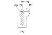
ここで、突出部15は、スリーブ側にあっても構わない。これについて、図4を用いて説明を加える。
図4は、変形例としてのスリーブ76と軸受ハウジング77との縦断面概略図である。図中、一点鎖線は流体動圧軸受の軸線を示している。
<5>
Since the
[5] Modifications The present invention is not limited to such embodiments, and various modifications or corrections can be made without departing from the scope of the present invention.
<1>
In the above embodiment, the inner
Here, the
FIG. 4 is a schematic longitudinal sectional view of a
スリーブ76は、環状の内周面76aをシャフト13(図1参照)の下部外周面13cに対向させて配置される中空状の部材である。スリーブ76の外周面76bは、軸線を含む断面が径方向外方に向けて凸となる凸曲面から構成されている。言い換えれば、スリーブ76の外周面76bは、上端部および下端部の径が中央部の径よりも小さく、それらの径が軸方向に連続的に変化する略俵状に形成されている。さらに言えば、外周面76bは、軸線上に中心を有する球面の一部であることがより好ましい。
軸受ハウジング77は、図1に示した軸受ハウジング17と外形がほぼ同様の部材である。軸受ハウジング77は、軸受ハウジング17と内周面77aの形状において相違している。軸受ハウジング17の内周面17aは、径方向内方に向けて凸となる凸曲面により構成されていたが、軸受ハウジング77の内周面77aは、軸線方向に延びる円筒状に形成されている。
スリーブ76の内周面76aと、シャフト13の下部外周面13cと、その間の径方向微少間隙に保持される潤滑油とによりラジアル軸受が構成される。軸受ハウジング77の軸方向上端に形成される環状面77bと、ロータハブ14の平坦面14b(図1参照)と、その間の軸方向微少間隙に保持される潤滑油とによりスラスト軸受が構成される。
The
The bearing
A radial bearing is configured by the inner
このような構成により、スリーブ76と軸受ハウジング77とは、スリーブ76の外周面76bと軸受ハウジング77の内周面77aとを当接させた状態で揺動運動することが可能となる。このため、ラジアル軸受を構成する内周面76aとスラスト軸受を構成する環状面77bとの直角精度を調整することができる。
また、この場合、スリーブ76を焼結する際、並びに内周面76aに動圧発生用溝をプレス成形する際に、外周面76bを略俵状に形成することが可能である。このため、従来のスリーブを製造する場合に比して特別な工程を必要としない。
なお、スリーブと軸受ハウジングとの変形例は、これに限定されない。例えば、スリーブと軸受ハウジングとの両方の対向面を相手方に向けて凸にするような構成も考えられる。あるいは、一方の対向面を他方の対向面に向けて凸形状に形成にするとともに、他方には、形成された凸形状に対応する凹形状を形成するとしてもよい。
また、上記実施形態では、軸受ハウジング17の内周面17aにおいて、周方向に連続して形成されていると説明したが、周方向に複数箇所(例えば、3箇所)に形成されていてもよい。
〈2〉
上記実施形態では、シャフト13がスピンドルモータの回転部材となる構成について説明した。
With such a configuration, the
In this case, when the
In addition, the modification of a sleeve and a bearing housing is not limited to this. For example, the structure which makes the opposing surface of both a sleeve and a bearing housing convex toward the other party is also considered. Alternatively, one opposing surface may be formed in a convex shape toward the other opposing surface, and a concave shape corresponding to the formed convex shape may be formed on the other.
In the above embodiment, the inner
<2>
In the above embodiment, the configuration in which the
ここで、シャフト13がスピンドルモータの静止部材となる場合にも本発明を適宜修正して適用することが可能である。
〈3〉
上記実施形態および変形例では、軸受ハウジング17(図1参照)あるいはスリーブ76(図4参照)は、軸線方向中間部において径方向内方あるいは外方に向けて突出する突出部を有すると説明した。
ここで、この突出部の軸線方向位置は、ラジアル軸受の軸支に寄与しない位置であってもよいし、ラジアル軸受の軸支に寄与する位置であってもよい。
例えば、図1において、軸受ハウジング17とスリーブ16とが当接する部分の軸線方向位置は、ラジアル動圧発生用溝41の軸線方向位置と同じであってもよいし、ラジアル動圧発生用溝41の軸線方向位置と異なっていてもよい。
〈4〉
上記実施形態では、軸受ハウジング17は、一体として形成されるカップ状部材である、と説明した。
ここで、軸受ハウジング17では、底部20が別体として形成されていてよい。この場合、軸受ハウジング17は、略円筒状の側部19の軸方向下端にカバー部材(カウンタプレート)としての底部20を固定した構造となる。
Here, even when the
<3>
In the embodiment and the modification described above, the bearing housing 17 (see FIG. 1) or the sleeve 76 (see FIG. 4) has been described as having a protruding portion that protrudes radially inward or outward at the axially intermediate portion. .
Here, the position of the protruding portion in the axial direction may be a position that does not contribute to the shaft support of the radial bearing, or may be a position that contributes to the shaft support of the radial bearing.
For example, in FIG. 1, the axial position of the portion where the bearing
<4>
In the said embodiment, the bearing
Here, in the bearing
〈5〉
また、上記実施形態で説明した発明は、例えば、特開2004−19755号公報に示された構造の流体動圧軸受に対して適用可能である。
すなわち、図1に示す流体動圧軸受10において、シャフト13の軸方向下端に径方向外方に延びるスラストフランジが形成される。スラストフランジは、シャフト13の軸方向下端から径方向外方に延びるとともに、スリーブ16の軸方向下端面と底部20の軸方向上側面との軸方向隙間に配置される。これにより、スラストフランジの軸方向下端面と底部20の軸方向上側面とが対向してスラスト軸受が形成される。
このような構造の流体動圧軸受は、上記実施形態に記載の流体動圧軸受10とラジアル軸受の構造において同様であるが、スラスト軸受の構造において相違している。しかし、このような構造の流体動圧軸受に対しても本発明を適用することにより、スラスト軸受を構成する底部20を有する軸受ハウジング17と、ラジアル軸受を構成するスリーブ16との直角精度を向上させることが可能となる。
また、上記実施形態で説明した発明は、例えば、特開2003−262217号公報に示された構造の流体動圧軸受に対して適用可能である。
<5>
Further, the invention described in the above embodiment can be applied to a fluid dynamic bearing having a structure disclosed in, for example, Japanese Patent Application Laid-Open No. 2004-19755.
That is, in the fluid dynamic pressure bearing 10 shown in FIG. 1, a thrust flange extending radially outward is formed at the axial lower end of the
The fluid dynamic pressure bearing having such a structure is similar in the structure of the fluid dynamic pressure bearing 10 and the radial bearing described in the above embodiment, but is different in the structure of the thrust bearing. However, by applying the present invention to the fluid dynamic bearing having such a structure, the right angle accuracy between the bearing
The invention described in the above embodiment is applicable to a fluid dynamic bearing having a structure disclosed in, for example, Japanese Patent Application Laid-Open No. 2003-262217.
すなわち、図1に示す流体動圧軸受10において、シャフト13の軸方向下端に径方向外方に延びるスラストフランジが形成される。スラストフランジは、シャフト13の軸方向下端から径方向外方に延びるとともに、スリーブ16の軸方向下端面と底部20の軸方向上側面との軸方向隙間に配置される。これにより、スラスト軸受部36に加えて、スリーブ16の軸方向下端面とスラストフランジの軸方向上端面とが対向してスラスト軸受が形成される。
このような構造の流体動圧軸受は、上記実施形態に記載の流体動圧軸受10とラジアル軸受の構造において同様であるが、スラスト軸受の構造において相違している。しかし、このような構造の流体動圧軸受に対しても本発明を適用することにより、スラスト軸受を構成する軸受ハウジング17と、ラジアル軸受を構成するスリーブ16との直角精度を向上させることが可能となる。
That is, in the fluid dynamic pressure bearing 10 shown in FIG. 1, a thrust flange extending radially outward is formed at the axial lower end of the
The fluid dynamic pressure bearing having such a structure is similar in the structure of the fluid dynamic pressure bearing 10 and the radial bearing described in the above embodiment, but is different in the structure of the thrust bearing. However, by applying the present invention to the fluid dynamic bearing having such a structure, it is possible to improve the right angle accuracy between the bearing
本発明は、より簡易かつ低コストに、ラジアル軸受とスラスト軸受との直角精度を高めた流体動圧軸受、その流体動圧軸受を備えるスピンドルモータ、記録ディスク駆動装置などとして有用である。 INDUSTRIAL APPLICABILITY The present invention is useful as a fluid dynamic pressure bearing in which the right angle accuracy between a radial bearing and a thrust bearing is improved, a spindle motor equipped with the fluid dynamic pressure bearing, a recording disk drive device, and the like in a simpler and lower cost manner.
10 流体動圧軸受 11 ハウジング
12 ハブ 13 シャフト
14 ロータハブ 15 突出部
16 スリーブ 17 軸受ハウジング
18 径方向微少間隙 19 側部
20 底部 21 縁部
23 環状突起部 24 接着剤
25 リング状の抜け止め 26 軸方向微少間隙
27 連通孔 30 環状突起部
35 ラジアル軸受部 36 スラスト軸受部
38 潤滑油 39 表面張力シール部
41 ラジアル動圧発生用溝 43 スラスト動圧発生用溝
50 ハードディスク装置 52 スピンドルモータ
53 記録ディスク 54 アクチュエータ部
55 アーム 56 磁気ヘッド
57 磁気ヘッド移動機構 62 ロータマグネット
63 ステータ 64 スラストヨーク
66 環状部 67 外周側部
DESCRIPTION OF
Claims (11)
前記シャフト基部の一端側に立設され、円筒状の外周面を有するシャフトと、
前記シャフトの前記外周面と径方向微少間隙を介して対向する内周面を有するスリーブと、
前記スリーブを内嵌する軸受ハウジングとを備え、
前記軸受ハウジングの軸方向他端には軸方向端面が形成され、
前記軸方向端面は、前記シャフト基部の軸方向一端側に形成された平坦面と軸方向微少間隙を介して対向し、
前記シャフトの前記外周面と、前記スリーブの前記内周面と、その間の前記径方向微少間隙に保持される動圧発生流体とによってラジアル軸受が構成され、
前記シャフト基部の前記平坦面と、前記軸受ハウジングの前記軸方向端面と、その間の前記軸方向微少間隙に保持される動圧発生流体とによってスラスト軸受が構成され、
前記スリーブの外周面あるいは前記軸受ハウジングの内周面のいずれか一方には、他方に向けて突出するとともに、その突出量が軸方向両側に向けて滑らかに減少する突出部が形成されている、
流体動圧軸受。 A shaft base;
A shaft erected on one end side of the shaft base and having a cylindrical outer peripheral surface;
A sleeve having an inner peripheral surface facing the outer peripheral surface of the shaft with a small radial gap;
A bearing housing in which the sleeve is fitted,
An axial end face is formed at the other axial end of the bearing housing,
The axial end surface is opposed to a flat surface formed on one axial end side of the shaft base through an axial small gap,
A radial bearing is configured by the outer peripheral surface of the shaft, the inner peripheral surface of the sleeve, and a dynamic pressure generating fluid held in the minute radial gap therebetween,
A thrust bearing is constituted by the flat surface of the shaft base, the axial end surface of the bearing housing, and a dynamic pressure generating fluid held in the minute axial gap therebetween,
Either one of the outer peripheral surface of the sleeve or the inner peripheral surface of the bearing housing is formed with a protruding portion that protrudes toward the other and whose protruding amount smoothly decreases toward both axial sides.
Fluid dynamic pressure bearing.
請求項1に記載の流体動圧軸受。 The protrusion is formed continuously in the circumferential direction on either the outer peripheral surface of the sleeve or the inner peripheral surface of the bearing housing.
The fluid dynamic pressure bearing according to claim 1.
請求項1または2に記載の流体動圧軸受。 The bearing housing is formed by pressing.
The fluid dynamic pressure bearing according to claim 1.
請求項1または2に記載の流体動圧軸受。 The bearing housing is made of resin.
The fluid dynamic pressure bearing according to claim 1.
請求項1〜4のいずれかに記載の流体動圧軸受。 The sleeve is made of sintered metal,
The fluid dynamic pressure bearing according to claim 1.
請求項1〜5のいずれかに記載の流体動圧軸受。 The sleeve and the bearing housing are fixed by filling a radial gap formed by the outer peripheral surface of the sleeve and the inner peripheral surface of the bearing housing with an adhesive,
The fluid dynamic pressure bearing according to claim 1.
請求項1〜6のいずれかに記載の流体動圧軸受。 The flat surface of the shaft base is orthogonal to the shaft;
The fluid dynamic pressure bearing according to claim 1.
前記シャフトあるいは前記スリーブのいずれかと一体的に回転するロータマグネットと、
前記ロータマグネットに対向して配置されるステータと、
を備えるスピンドルモータ。 A fluid dynamic pressure bearing according to any one of claims 1 to 7,
A rotor magnet that rotates integrally with either the shaft or the sleeve;
A stator disposed opposite to the rotor magnet;
Spindle motor with
前記ハウジングに固定されるスピンドルモータであって、情報を記録できるディスク状記録媒体を回転させる請求項7に記載のスピンドルモータと、
前記記録媒体の所要の位置に情報を書き込むまたは読み出すための情報アクセス手段と、
を備える記録ディスク駆動装置。 A housing;
The spindle motor according to claim 7, wherein the spindle motor is fixed to the housing and rotates a disk-shaped recording medium capable of recording information.
Information access means for writing or reading information to a required position of the recording medium;
A recording disk drive comprising:
前記スリーブの外周面あるいは前記軸受ハウジングの内周面のいずれか一方に形成され、他方に向けて突出するとともに、その突出量が軸方向両側に向けて滑らかに減少する突出部を、他方と接触させて嵌合する嵌合工程と、
前記スリーブの外周面と前記軸受ハウジングの内周面との少なくとも一方に接着剤を塗布する接着剤塗布工程と、
前記スリーブの前記内周面と前記軸受ハウジングの軸方向端面との直角精度を調整する直角精度調整工程と、
を備える流体動圧軸受の製造方法。 A fluid dynamic pressure bearing comprising: a shaft having a cylindrical outer peripheral surface; a sleeve having an inner peripheral surface facing the outer peripheral surface of the shaft with a small radial gap; and a bearing housing in which the sleeve is fitted. A manufacturing method comprising:
A protruding portion formed on either the outer peripheral surface of the sleeve or the inner peripheral surface of the bearing housing and protruding toward the other and whose protruding amount decreases smoothly toward both axial sides contacts the other. A mating process for mating, and
An adhesive application step of applying an adhesive to at least one of the outer peripheral surface of the sleeve and the inner peripheral surface of the bearing housing;
A right angle accuracy adjusting step for adjusting a right angle accuracy between the inner peripheral surface of the sleeve and an axial end surface of the bearing housing;
A method of manufacturing a fluid dynamic pressure bearing.
請求項10に記載の流体動圧軸受の製造方法。 The right angle accuracy adjusting step includes a step of adjusting a right angle accuracy between the inner peripheral surface of the sleeve and the axial end surface of the bearing housing by using a jig, curing the adhesive, and the sleeve and the bearing housing. And fixing the
A method for manufacturing a fluid dynamic pressure bearing according to claim 10.
Priority Applications (1)
| Application Number | Priority Date | Filing Date | Title |
|---|---|---|---|
| JP2004289561A JP2006105183A (en) | 2004-10-01 | 2004-10-01 | Method of manufacturing hydrodynamic pressure bearing, spindle motor and recording disk driving device |
Applications Claiming Priority (1)
| Application Number | Priority Date | Filing Date | Title |
|---|---|---|---|
| JP2004289561A JP2006105183A (en) | 2004-10-01 | 2004-10-01 | Method of manufacturing hydrodynamic pressure bearing, spindle motor and recording disk driving device |
Publications (2)
| Publication Number | Publication Date |
|---|---|
| JP2006105183A true JP2006105183A (en) | 2006-04-20 |
| JP2006105183A5 JP2006105183A5 (en) | 2007-10-25 |
Family
ID=36375176
Family Applications (1)
| Application Number | Title | Priority Date | Filing Date |
|---|---|---|---|
| JP2004289561A Withdrawn JP2006105183A (en) | 2004-10-01 | 2004-10-01 | Method of manufacturing hydrodynamic pressure bearing, spindle motor and recording disk driving device |
Country Status (1)
| Country | Link |
|---|---|
| JP (1) | JP2006105183A (en) |
Cited By (2)
| Publication number | Priority date | Publication date | Assignee | Title |
|---|---|---|---|---|
| JP2008025739A (en) * | 2006-07-21 | 2008-02-07 | Ntn Corp | Manufacturing method of dynamic pressure bearing device |
| JP2009281464A (en) * | 2008-05-21 | 2009-12-03 | Ntn Corp | Fluid bearing device |
-
2004
- 2004-10-01 JP JP2004289561A patent/JP2006105183A/en not_active Withdrawn
Cited By (3)
| Publication number | Priority date | Publication date | Assignee | Title |
|---|---|---|---|---|
| JP2008025739A (en) * | 2006-07-21 | 2008-02-07 | Ntn Corp | Manufacturing method of dynamic pressure bearing device |
| JP4732262B2 (en) * | 2006-07-21 | 2011-07-27 | Ntn株式会社 | Method for manufacturing hydrodynamic bearing device |
| JP2009281464A (en) * | 2008-05-21 | 2009-12-03 | Ntn Corp | Fluid bearing device |
Similar Documents
| Publication | Publication Date | Title |
|---|---|---|
| KR101098791B1 (en) | Dynamic pressure bearing device and motor using the same | |
| JP2005045924A (en) | Spindle motor, method of manufacturing rotor applied to the spindle motor, and hard disc drive equipped with the spindle motor | |
| US20090160277A1 (en) | Fluid Dynamic Pressure Bearing | |
| JP2006038211A (en) | Fluid dynamic pressure bearing, spindle motor having this fluid dynamic pressure bearing and recording disk driving device having this spindle motor | |
| JP2010138992A (en) | Bearing device, spindle motor, and disk drive unit | |
| JP2006153269A (en) | Kinetic pressure bearing unit | |
| JP2007263228A (en) | Dynamic pressure bearing device | |
| US7663280B2 (en) | Spindle motor and disk drive device using the same | |
| JP2009008200A (en) | Fluid bearing device and spindle motor | |
| JP3774080B2 (en) | Hydrodynamic bearing unit | |
| JP2007107622A (en) | Dynamic pressure bearing device and spindle motor using it | |
| KR100377000B1 (en) | Spindle motor | |
| JP2006300245A (en) | Dynamic fluid bearing device | |
| WO2015087809A1 (en) | Fluid dynamic bearing device and motor provided therewith | |
| JP4754794B2 (en) | Fluid bearing unit, spindle motor having the fluid bearing unit, and recording disk drive | |
| JP2006105183A (en) | Method of manufacturing hydrodynamic pressure bearing, spindle motor and recording disk driving device | |
| JP4619691B2 (en) | Hydrodynamic bearing device and motor using the same | |
| JP4080229B2 (en) | Hydrodynamic bearing, spindle motor, and recording disk drive | |
| JP2006325329A (en) | Spindle motor and recording disk driving device using same | |
| JP4661014B2 (en) | DYNAMIC PRESSURE BEARING DEVICE AND SPINDLE MOTOR HAVING THE DYNAMIC PRESSURE BEARING DEVICE | |
| JP2004316680A (en) | Spindle motor and recording disk driving mechanism with the same | |
| JP2005291428A (en) | Fluid dynamic pressure bearing, spindle motor and recording disk driving device | |
| JP2002266878A (en) | Dynamic pressure bearing device and its manufacturing method | |
| JP2005337341A (en) | Dynamic pressure bearing device and motor using the same | |
| JP2006353082A (en) | Spindle motor and disk driver using same |
Legal Events
| Date | Code | Title | Description |
|---|---|---|---|
| A521 | Written amendment |
Free format text: JAPANESE INTERMEDIATE CODE: A523 Effective date: 20070910 |
|
| A621 | Written request for application examination |
Effective date: 20070910 Free format text: JAPANESE INTERMEDIATE CODE: A621 |
|
| A761 | Written withdrawal of application |
Free format text: JAPANESE INTERMEDIATE CODE: A761 Effective date: 20090114 |