JP2006103541A - Controller for vehicle drive unit - Google Patents

Controller for vehicle drive unit Download PDF

Info

Publication number
JP2006103541A
JP2006103541A JP2004293795A JP2004293795A JP2006103541A JP 2006103541 A JP2006103541 A JP 2006103541A JP 2004293795 A JP2004293795 A JP 2004293795A JP 2004293795 A JP2004293795 A JP 2004293795A JP 2006103541 A JP2006103541 A JP 2006103541A
Authority
JP
Japan
Prior art keywords
state
engine
switching
transmission
speed
Prior art date
Legal status (The legal status is an assumption and is not a legal conclusion. Google has not performed a legal analysis and makes no representation as to the accuracy of the status listed.)
Pending
Application number
JP2004293795A
Other languages
Japanese (ja)
Other versions
JP2006103541A5 (en
Inventor
Atsushi Tabata
淳 田端
Yutaka Taga
豊 多賀
Current Assignee (The listed assignees may be inaccurate. Google has not performed a legal analysis and makes no representation or warranty as to the accuracy of the list.)
Toyota Motor Corp
Original Assignee
Toyota Motor Corp
Priority date (The priority date is an assumption and is not a legal conclusion. Google has not performed a legal analysis and makes no representation as to the accuracy of the date listed.)
Filing date
Publication date
Application filed by Toyota Motor Corp filed Critical Toyota Motor Corp
Priority to JP2004293795A priority Critical patent/JP2006103541A/en
Publication of JP2006103541A publication Critical patent/JP2006103541A/en
Publication of JP2006103541A5 publication Critical patent/JP2006103541A5/ja
Pending legal-status Critical Current

Links

Images

Classifications

    • YGENERAL TAGGING OF NEW TECHNOLOGICAL DEVELOPMENTS; GENERAL TAGGING OF CROSS-SECTIONAL TECHNOLOGIES SPANNING OVER SEVERAL SECTIONS OF THE IPC; TECHNICAL SUBJECTS COVERED BY FORMER USPC CROSS-REFERENCE ART COLLECTIONS [XRACs] AND DIGESTS
    • Y02TECHNOLOGIES OR APPLICATIONS FOR MITIGATION OR ADAPTATION AGAINST CLIMATE CHANGE
    • Y02TCLIMATE CHANGE MITIGATION TECHNOLOGIES RELATED TO TRANSPORTATION
    • Y02T10/00Road transport of goods or passengers
    • Y02T10/60Other road transportation technologies with climate change mitigation effect
    • Y02T10/62Hybrid vehicles
    • YGENERAL TAGGING OF NEW TECHNOLOGICAL DEVELOPMENTS; GENERAL TAGGING OF CROSS-SECTIONAL TECHNOLOGIES SPANNING OVER SEVERAL SECTIONS OF THE IPC; TECHNICAL SUBJECTS COVERED BY FORMER USPC CROSS-REFERENCE ART COLLECTIONS [XRACs] AND DIGESTS
    • Y02TECHNOLOGIES OR APPLICATIONS FOR MITIGATION OR ADAPTATION AGAINST CLIMATE CHANGE
    • Y02TCLIMATE CHANGE MITIGATION TECHNOLOGIES RELATED TO TRANSPORTATION
    • Y02T10/00Road transport of goods or passengers
    • Y02T10/60Other road transportation technologies with climate change mitigation effect
    • Y02T10/72Electric energy management in electromobility

Abstract

<P>PROBLEM TO BE SOLVED: To provide a controller for improving the durability of an engagement device installed for switching a power transmission path from an engine to a driving wheel to a power transmission interrupting state and a power transmission enabled state in a vehicle drive unit equipped with a differential mechanism whose differential action is operable and a transmission. <P>SOLUTION: When a shift lever 48 is switched to a non-driving position, rotation control is performed by an engine rotation control means 84 so that an engine rotating speed N<SB>E</SB>can be prevented from being a predetermined engine rotating speed N<SB>E</SB>' or more. When the shift lever 48 is switched from a non-driving position to a driving position, a first clutch C1 and/or a second clutch C2 is engaged in a state that the engine torque T<SB>E</SB>is suppressed according to the switching so that the durability of the first clutch C1 and/or the second clutch C2 can be improved. <P>COPYRIGHT: (C)2006,JPO&NCIPI

Description

本発明は、車両用駆動装置の制御装置に係り、差動作用が作動可能な差動機構とその差動機構から駆動輪への動力伝達経路の一部を構成する変速機とを備える車両用駆動装置において、特に、エンジンから駆動輪への動力伝達経路を動力伝達遮断状態と動力伝達可能状態とに切り換えるための係合装置の耐久性を向上する技術に関するものである。   The present invention relates to a control device for a vehicle drive device, and includes a differential mechanism that can operate a differential action and a transmission that forms part of a power transmission path from the differential mechanism to a drive wheel. In particular, the present invention relates to a technique for improving the durability of an engagement device for switching a power transmission path from an engine to a drive wheel between a power transmission cutoff state and a power transmission enable state.

機械的に力の合成、分配を行うことのできる差動機構とその差動機構に連結された電動機とを備えた車両用駆動装置が知られている。例えば、特許文献1に記載されたハイブリッド車両用駆動装置がそれである。このようなハイブリッド車両用駆動装置では差動機構に遊星歯車装置が用いられ、電動機による反力トルクに応じてエンジンから駆動輪への動力伝達が行われる所謂電気式トルコンが構成されている。また、特許文献1の車両用駆動装置は、遊星歯車装置と駆動輪との間の動力伝達経路に有段式自動変速機が備えられ、その有段式自動変速機内のクラッチの解放と係合とが制御されてエンジンと駆動輪との間の動力伝達経路が動力伝達遮断状態と動力伝達可能状態とに切り換えられる。さらに、特許文献1の車両には、この動力伝達遮断状態と動力伝達可能状態との切換えのために、動力伝達経路を動力伝達遮断状態とする非駆動ポジションと動力伝達経路を動力伝達可能状態とする駆動ポジションとが手動操作により切り換え可能なシフト切換装置が備えられている。   2. Description of the Related Art A vehicle drive device is known that includes a differential mechanism capable of mechanically combining and distributing forces and an electric motor connected to the differential mechanism. For example, this is a hybrid vehicle drive device described in Patent Document 1. In such a hybrid vehicle drive device, a planetary gear device is used for the differential mechanism, and a so-called electric torque converter is configured in which power is transmitted from the engine to the drive wheels in accordance with the reaction torque generated by the electric motor. The vehicle drive device of Patent Document 1 includes a stepped automatic transmission in a power transmission path between the planetary gear device and the drive wheels, and releases and engages a clutch in the stepped automatic transmission. And the power transmission path between the engine and the drive wheels is switched between a power transmission cutoff state and a power transmission enable state. Further, in the vehicle of Patent Document 1, in order to switch between the power transmission cutoff state and the power transmission possible state, the non-driving position where the power transmission path is in the power transmission cutoff state and the power transmission path are in the power transmission possible state. There is provided a shift switching device capable of switching between the driving position to be manually operated.

特開平9−308010号公報JP 9-308010 A 特開平1−113531号公報Japanese Patent Laid-Open No. 1-113531 実開平1−76336号公報Japanese Utility Model Publication No. 1-76336

そして、上記シフト切換装置が非駆動ポジションから駆動ポジションへマニュアルシフトされたときには、エンジン作動時であればそのエンジンの出力トルク(以下、エンジントルクという)が有段式自動変速機を介して駆動輪に伝達される。   When the shift switching device is manually shifted from the non-driving position to the driving position, the engine output torque (hereinafter referred to as engine torque) is driven through the stepped automatic transmission during engine operation. Is transmitted to.

しかしながら、この非駆動ポジションから駆動ポジションへのマニュアルシフトの際に、伝達されるエンジントルクが大きい程動力伝達経路を動力伝達遮断状態と動力伝達可能状態とに切り換えるための係合装置の耐久性が低下する可能性があった。   However, in the manual shift from the non-drive position to the drive position, the durability of the engagement device for switching the power transmission path between the power transmission cut-off state and the power transmission possible state increases as the transmitted engine torque increases. There was a possibility of decline.

本発明は、以上の事情を背景として為されたものであり、その目的とするところは、差動作用が作動可能な差動機構とその差動機構から駆動輪への動力伝達経路の一部を構成する変速機とを備える車両用駆動装置において、エンジンから駆動輪への動力伝達経路を動力伝達遮断状態と動力伝達可能状態とに切り換えるために備えられた係合装置の耐久性が向上する制御装置を提供することにある。   The present invention has been made against the background of the above circumstances, and its purpose is to provide a differential mechanism capable of operating a differential action and a part of a power transmission path from the differential mechanism to a drive wheel. In the vehicle drive device including the transmission that constitutes the transmission, the durability of the engagement device provided for switching the power transmission path from the engine to the driving wheel between the power transmission cut-off state and the power transmission-capable state is improved. It is to provide a control device.

すなわち、請求項1にかかる発明の要旨とするところは、(a) エンジンの出力を第1電動機および伝達部材へ分配する差動機構とその伝達部材から駆動輪への動力伝達経路に設けられた第2電動機とを有する差動部と、前記動力伝達経路の一部を構成し変速機として機能する変速部とを備えた車両用駆動装置の制御装置であって、(b) 前記エンジンから前記駆動輪への動力伝達経路を、動力伝達可能状態と動力伝達遮断状態とに選択的に切り換える係合装置と、(c) その係合装置による前記動力伝達可能状態への切換えを選択するための駆動ポジションとその係合装置による前記動力伝達遮断状態への切換えを選択するための非駆動ポジションとに切り換える切換装置と、(d) その切換装置が前記非駆動ポジションへ切り換えられているときには、前記エンジンの回転速度が所定エンジン回転速度以上とならないように回転制御するエンジン回転制御手段とを、含むことにある。   That is, the gist of the invention according to claim 1 is that: (a) a differential mechanism that distributes engine output to the first electric motor and the transmission member, and a power transmission path from the transmission member to the drive wheels; A control device for a vehicle drive device, comprising: a differential portion having a second electric motor; and a transmission portion that constitutes a part of the power transmission path and functions as a transmission, and (b) from the engine An engagement device that selectively switches a power transmission path to the drive wheel between a power transmission enable state and a power transmission cut-off state; and (c) for selecting switching to the power transmission enable state by the engagement device. A switching device that switches between a driving position and a non-driving position for selecting switching to the power transmission cutoff state by the engagement device; and (d) when the switching device is switched to the non-driving position. And engine rotation control means for controlling the rotation so that the rotation speed of the engine does not exceed a predetermined engine rotation speed.

このようにすれば、差動作用が作動可能な差動機構を有する差動部と変速部とを備える駆動装置において、動力伝達経路を動力伝達可能状態と動力伝達遮断状態とに選択的に切り換える係合装置による動力伝達可能状態への切換えを選択するための駆動ポジションとその係合装置による動力伝達遮断状態への切換えを選択するための非駆動ポジションとに切り換える切換装置が非駆動ポジションへ切り換えられているときには、エンジン回転制御手段によりエンジン回転速度が所定エンジン回転速度以上とならないように回転制御されるので、上記切換装置が非駆動ポジションから駆動ポジションへ切り換えられたときに、その切換えに伴って駆動輪へ伝達されるエンジントルクすなわちその切換えに伴って係合される上記係合装置が伝達すべきエンジントルクが抑制される。よって、エンジントルクが抑制された状態で上記係合装置が係合されてその係合装置の耐久性が向上する。   According to this configuration, in the drive device including the differential unit having the differential mechanism capable of operating the differential action and the transmission unit, the power transmission path is selectively switched between the power transmission enable state and the power transmission cutoff state. A switching device that switches between a driving position for selecting switching to a power transmission enabled state by the engagement device and a non-driving position for selecting switching to a power transmission cutoff state by the engagement device switches to a non-driving position. When the switching device is switched from the non-drive position to the drive position, the engine rotation control means controls the rotation so that the engine rotation speed does not exceed the predetermined engine rotation speed. The engine torque transmitted to the drive wheels, that is, the engagement device engaged with the switching is transmitted. Can engine torque is suppressed. Therefore, the engagement device is engaged with the engine torque being suppressed, and the durability of the engagement device is improved.

また、請求項2にかかる発明では、前記エンジン回転制御手段は、エンジンの出力を制御することにより前記エンジンの回転速度が所定エンジン回転速度以上とならないように回転制御するものであり、前記切換装置が前記非駆動ポジションへ切り換えられているときには、前記第1電動機および前記第2電動機を無負荷状態とする電動機制御手段を更に含むものである。このようにすれば、エンジン回転速度が所定エンジン回転速度以上とならないようにする回転制御が、エンジン回転制御手段によりエンジンの出力を制御することにより実行されるので、前記第1電動機および/または前記第2電動機を作動させてエンジン回転速度を回転制御する必要性が低くなることから電動機制御手段により前記第1電動機および前記第2電動機が無負荷状態とされてそれら電動機を制御する為の電気的エネルギー損失が抑制され得る。よって、燃費が向上する。また、電動機制御手段により前記第1電動機および前記第2電動機が無負荷状態とされると、差動部がエンジントルクの伝達が不能な状態すなわち差動部が動力伝達経路が遮断された電気的に中立状態(ニュートラル)とされるので、切換装置が非駆動ポジションから駆動ポジションへ切り換えられたときにはエンジントルクが伝達されてない状態で前記係合装置が係合されてその係合装置の耐久性が一層向上する。   In the invention according to claim 2, the engine rotation control means controls the rotation of the engine so that the rotation speed of the engine does not exceed a predetermined engine rotation speed by controlling the output of the engine. When the motor is switched to the non-driving position, it further includes motor control means for putting the first motor and the second motor into a no-load state. In this case, the rotation control for preventing the engine rotation speed from exceeding the predetermined engine rotation speed is executed by controlling the output of the engine by the engine rotation control means. Therefore, the first electric motor and / or the Since the necessity of operating the second electric motor to control the rotation speed of the engine is reduced, the electric motor for controlling the electric motor when the first electric motor and the second electric motor are brought into a no-load state by the electric motor control means. Energy loss can be suppressed. Therefore, fuel consumption is improved. In addition, when the first motor and the second motor are brought into a no-load state by the motor control means, the differential unit is in a state where the engine torque cannot be transmitted, that is, the differential unit is electrically disconnected from the power transmission path. Therefore, when the switching device is switched from the non-driving position to the driving position, the engagement device is engaged without the engine torque being transmitted, and the durability of the engagement device is determined. Is further improved.

また、請求項3にかかる発明の要旨とするところは、(a) エンジンの出力を第1電動機および伝達部材へ分配する差動機構とその伝達部材から駆動輪への動力伝達経路に設けられた第2電動機とを有する差動部と、前記動力伝達経路の一部を構成し変速機として機能する変速部とを備えた車両用駆動装置の制御装置であって、(b) 前記エンジンから前記駆動輪への動力伝達経路を、動力伝達可能状態と動力伝達遮断状態とに選択的に切り換える係合装置と、(c) その係合装置による前記動力伝達可能状態への切換えを選択するための駆動ポジションとその係合装置による前記動力伝達遮断状態への切換えを選択するための非駆動ポジションとに切り換える切換装置と、(d) その切換装置が前記非駆動ポジションへ切り換えられているときには、前記第1電動機および前記第2電動機を無負荷状態とする電動機制御手段とを、含むことにある。   According to a third aspect of the present invention, there is provided (a) a differential mechanism that distributes engine output to the first electric motor and the transmission member, and a power transmission path from the transmission member to the drive wheels. A control device for a vehicle drive device, comprising: a differential portion having a second electric motor; and a transmission portion that constitutes a part of the power transmission path and functions as a transmission, and (b) from the engine An engagement device that selectively switches a power transmission path to the drive wheel between a power transmission enable state and a power transmission cut-off state; and (c) for selecting switching to the power transmission enable state by the engagement device. A switching device that switches between a driving position and a non-driving position for selecting switching to the power transmission cut-off state by the engagement device; and (d) when the switching device is switched to the non-driving position, And a motor control means for bringing the first motor and the second motor into a no-load state.

このようにすれば、差動作用が作動可能な差動機構を有する差動部と変速部とを備える駆動装置において、動力伝達経路を動力伝達可能状態と動力伝達遮断状態とに選択的に切り換える係合装置による動力伝達可能状態への切換えを選択するための駆動ポジションとその係合装置による動力伝達遮断状態への切換えを選択するための非駆動ポジションとに切り換える切換装置が非駆動ポジションへ切り換えられているときには、電動機制御手段により前記第1電動機および前記第2電動機が無負荷状態とされるので、差動部が電気的に中立状態(ニュートラル)とされて上記切換装置が非駆動ポジションから駆動ポジションへ切り換えられたときに、その切換えに伴って駆動輪へエンジントルクが伝達されないすなわちその切換えに伴って係合される上記係合装置にエンジントルクが伝達されない。よって、エンジントルクが伝達されてない状態で前記係合装置が係合されてその係合装置の耐久性が向上する。また、電動機制御手段により前記第1電動機および前記第2電動機が無負荷状態とされてそれら電動機を制御する為の電気的エネルギー損失が抑制されるので、燃費が向上する。   According to this configuration, in the drive device including the differential unit having the differential mechanism capable of operating the differential action and the transmission unit, the power transmission path is selectively switched between the power transmission enable state and the power transmission cutoff state. A switching device that switches between a driving position for selecting switching to a power transmission enabled state by the engagement device and a non-driving position for selecting switching to a power transmission cutoff state by the engagement device switches to a non-driving position. Since the first motor and the second motor are brought into a no-load state by the motor control means, the differential unit is electrically neutralized (neutral) and the switching device is moved from the non-driving position. When switching to the drive position, engine torque is not transmitted to the drive wheels along with the switching, i.e. Engine torque to the engagement device is not transmitted to be. Therefore, the engagement device is engaged in a state where the engine torque is not transmitted, and the durability of the engagement device is improved. In addition, since the first motor and the second motor are brought into a no-load state by the motor control means, and electrical energy loss for controlling these motors is suppressed, fuel efficiency is improved.

また、請求項4にかかる発明では、前記変速部は有段式自動変速機であるとともに、前記係合装置はその有段式自動変速機の変速段を成立させるために用いられるものであり、前記切換装置が前記非駆動ポジションへ切り換えられているときには、その係合装置によりその有段式自動変速機が動力伝達遮断状態とされるものである。このようにすれば、切換装置の非駆動ポジション時に動力伝達経路を簡単に動力伝達遮断状態とすることができる。   In the invention according to claim 4, the transmission unit is a stepped automatic transmission, and the engagement device is used to establish a shift stage of the stepped automatic transmission, When the switching device is switched to the non-driving position, the stepped automatic transmission is brought into a power transmission cut-off state by the engaging device. If it does in this way, a power transmission path can be easily made into a power transmission interruption state at the time of a non-driving position of a switching device.

また、請求項5にかかる発明では、前記差動機構は、その差動機構を差動状態とロック状態とに選択的に切り換えるための差動状態切換装置を備え、前記切換装置が前記非駆動ポジションへ切り換えられているときには、前記差動状態切換装置により前記差動機構が差動状態とされるものである。このようにすれば、差動機構が差動状態と非差動状態とに切り換え可能に構成される。また、前記差動機構が差動状態においては、差動機構のロック状態と異なり差動機構の各回転要素の自由度が確保されるので、例えば前記電動機制御手段により前記第1電動機および前記第2電動機が無負荷状態とされて差動部が電気的に中立状態(ニュートラル)とされ得る。また、前記変速部が有段式自動変速機である場合には、差動機構の差動状態において前記差動部と前記変速部とで無段変速機が構成され、差動機構のロック状態において前記差動部と前記変速部とで有段変速機が構成される。   In the invention according to claim 5, the differential mechanism includes a differential state switching device for selectively switching the differential mechanism between a differential state and a locked state, and the switching device is not driven. When the position is switched to the position, the differential mechanism is brought into a differential state by the differential state switching device. In this way, the differential mechanism can be switched between a differential state and a non-differential state. In addition, when the differential mechanism is in the differential state, the degree of freedom of each rotating element of the differential mechanism is ensured unlike the locked state of the differential mechanism, so that, for example, the first motor and the first motor are controlled by the motor control means. The two motors can be in a no-load state, and the differential unit can be in an electrically neutral state (neutral). Further, when the transmission unit is a stepped automatic transmission, the differential unit and the transmission unit form a continuously variable transmission in the differential state of the differential mechanism, and the differential mechanism is locked. In FIG. 4, the differential unit and the transmission unit constitute a stepped transmission.

ここで、好適には、前記差動機構は、前記エンジンに連結された第1要素と前記第1電動機に連結された第2要素と前記伝達部材に連結された第3要素とを有するものであり、前記差動状態切換装置は、前記差動状態とするためにその第1要素乃至第3要素を相互に相対回転可能とし、前記ロック状態とするためにその第1要素乃至第3要素を共に一体回転させるか或いはその第2要素を非回転状態とするものである。このようにすれば、差動機構が差動状態とロック状態とに切り換えられるように構成される。   Preferably, the differential mechanism includes a first element coupled to the engine, a second element coupled to the first electric motor, and a third element coupled to the transmission member. And the differential state switching device is configured such that the first to third elements can be rotated relative to each other in order to set the differential state, and the first to third elements are set to be in the locked state. Both are integrally rotated, or the second element is in a non-rotating state. In this way, the differential mechanism is configured to be switched between the differential state and the lock state.

また、好適には、前記差動状態切換装置は、前記第1要素乃至第3要素を共に一体回転させるために前記第1要素乃至第3要素のうちの少なくとも2つを相互に連結するクラッチおよび/または前記第2要素を非回転状態とするために前記第2要素を非回転部材に連結するブレーキを備えたものである。このようにすれば、差動機構が差動状態とロック状態とに簡単に切り換えられるように構成される。   Preferably, the differential state switching device includes a clutch that connects at least two of the first to third elements with each other in order to rotate the first to third elements together. In order to put the second element in a non-rotating state, a brake for connecting the second element to a non-rotating member is provided. In this way, the differential mechanism can be easily switched between the differential state and the locked state.

また、好適には、前記差動機構は、前記クラッチおよび前記ブレーキの解放により前記第1回転要素乃至第3回転要素を相互に相対回転可能な差動状態とされて電気的な差動装置とされ、前記クラッチの係合により変速比が1である変速機とされるか、或いは前記ブレーキの係合により変速比が1より小さい増速変速機とされるものである。このようにすれば、差動機構が差動状態とロック状態とに切り換えられるように構成されるとともに、単段または複数段の定変速比を有する変速機としても構成され得る。   Preferably, the differential mechanism is configured to be in a differential state in which the first to third rotating elements can be rotated relative to each other by releasing the clutch and the brake. Then, the transmission is a transmission having a gear ratio of 1 by the engagement of the clutch, or the speed increasing transmission having a transmission ratio of less than 1 by the engagement of the brake. In this way, the differential mechanism can be configured to be switched between the differential state and the locked state, and can also be configured as a transmission having a single-stage or multiple-stage constant gear ratio.

また、好適には、前記差動機構動は遊星歯車装置であり、前記第1要素はその遊星歯車装置のキャリヤであり、前記第2要素はその遊星歯車装置のサンギヤであり、前記第3要素はその遊星歯車装置のリングギヤである。このようにすれば、前記差動機構の軸方向寸法が小さくなる。また、差動機構が1つの遊星歯車装置によって簡単に構成され得る。   Preferably, the differential mechanism movement is a planetary gear device, the first element is a carrier of the planetary gear device, the second element is a sun gear of the planetary gear device, and the third element. Is the ring gear of the planetary gear unit. In this way, the axial dimension of the differential mechanism is reduced. Further, the differential mechanism can be easily constituted by one planetary gear device.

また、好適には、前記遊星歯車装置はシングルピニオン型遊星歯車装置である。このようにすれば、前記差動機構の軸方向寸法が小さくなる。また、差動機構が1つのシングルピニオン型遊星歯車装置によって簡単に構成される。   Preferably, the planetary gear device is a single pinion type planetary gear device. In this way, the axial dimension of the differential mechanism is reduced. Further, the differential mechanism is simply constituted by one single pinion type planetary gear device.

また、好適には、前記変速部の変速比と前記差動部の変速比とに基づいて前記車両用駆動装置の総合変速比が形成されるものである。このようにすれば、変速部の変速比を利用することによって駆動力が幅広く得られるようになる。   Preferably, the overall speed ratio of the vehicle drive device is formed based on the speed ratio of the speed change portion and the speed change ratio of the differential portion. In this way, a wide driving force can be obtained by utilizing the gear ratio of the transmission unit.

以下、本発明の実施例を図面を参照しつつ詳細に説明する。   Hereinafter, embodiments of the present invention will be described in detail with reference to the drawings.

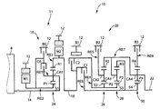
図1は、本発明の一実施例である制御装置が適用されるハイブリッド車両の駆動装置の一部を構成する変速機構10を説明する骨子図である。図1において、変速機構10は車体に取り付けられる非回転部材としてのトランスミッションケース12(以下、ケース12という)内において共通の軸心上に配設された入力回転部材としての入力軸14と、この入力軸14に直接に或いは図示しない脈動吸収ダンパー(振動減衰装置)を介して直接に連結された差動部11と、その差動部11と駆動輪38との間の動力伝達経路で伝達部材(伝動軸)18を介して直列に連結されている有段式の変速機として機能する変速部としての自動変速部20と、この自動変速部20に連結されている出力回転部材としての出力軸22とを直列に備えている。この変速機構10は、車両において縦置きされるFR(フロントエンジン・リヤドライブ)型車両に好適に用いられるものであり、入力軸14に直接に或いは図示しない脈動吸収ダンパーを介して直接的に連結された走行用の駆動力源として例えばガソリンエンジンやディーゼルエンジン等の内燃機関であるエンジン8と一対の駆動輪38(図5参照)との間に設けられて、エンジン8からの動力を動力伝達経路の一部を構成する差動歯車装置(終減速機)36および一対の車軸等を順次介して左右の駆動輪38へ伝達する。   FIG. 1 is a skeleton diagram illustrating a speed change mechanism 10 that constitutes a part of a drive device of a hybrid vehicle to which a control device according to an embodiment of the present invention is applied. In FIG. 1, a transmission mechanism 10 includes an input shaft 14 as an input rotation member disposed on a common axis in a transmission case 12 (hereinafter referred to as case 12) as a non-rotation member attached to a vehicle body, A differential member 11 directly connected to the input shaft 14 or directly via a pulsation absorbing damper (vibration damping device) (not shown), and a transmission member in a power transmission path between the differential unit 11 and the drive wheel 38 An automatic transmission unit 20 as a transmission unit that functions as a stepped transmission connected in series via a (transmission shaft) 18, and an output shaft as an output rotation member connected to the automatic transmission unit 20 22 in series. The speed change mechanism 10 is preferably used in an FR (front engine / rear drive) type vehicle vertically installed in a vehicle, and is directly connected to the input shaft 14 or directly via a pulsation absorbing damper (not shown). As a driving power source for traveling, for example, an engine 8 which is an internal combustion engine such as a gasoline engine or a diesel engine is provided between a pair of driving wheels 38 (see FIG. 5), and power from the engine 8 is transmitted. The differential gear device (final reduction gear) 36 and a pair of axles that constitute a part of the path are sequentially transmitted to the left and right drive wheels 38.

上述のように、本実施例の変速機構10においてはエンジン8と差動部11とは直結されている。この直結にはトルクコンバータやフルードカップリング等の流体式伝動装置を介することなく連結されているということであり、例えば上記脈動吸収ダンパーなどを介する連結はこの直結に含まれる。なお、変速機構10はその軸心に対して対称的に構成されているため、図1の骨子図においてはその下側が省略されている。以下の各実施例についても同様である。   As described above, in the transmission mechanism 10 of the present embodiment, the engine 8 and the differential unit 11 are directly connected. This direct connection means that the connection is made without using a hydraulic power transmission device such as a torque converter or a fluid coupling. For example, the connection via the pulsation absorbing damper is included in this direct connection. Since the speed change mechanism 10 is configured symmetrically with respect to its axis, the lower side is omitted in the skeleton diagram of FIG. The same applies to each of the following embodiments.

差動部11は、第1電動機M1と、入力軸14に入力されたエンジン8の出力を機械的に分配する機械的機構であってエンジン8の出力を第1電動機M1および伝達部材18に分配する差動機構としての動力分配機構16と、伝達部材18と一体的に回転するように設けられている第2電動機M2とを備えている。なお、この第2電動機M2は伝達部材18から駆動輪38までの間の動力伝達経路を構成するいずれの部分に設けられてもよい。本実施例の第1電動機M1および第2電動機M2は発電機能をも有する所謂モータジェネレータであるが、第1電動機M1は反力を発生させるためのジェネレータ(発電)機能を少なくとも備え、第2電動機M2は走行用の駆動力源として駆動力を出力するためのモータ(電動機)機能を少なくとも備える。   The differential unit 11 is a mechanical mechanism that mechanically distributes the output of the engine 8 input to the first electric motor M1 and the input shaft 14, and distributes the output of the engine 8 to the first electric motor M1 and the transmission member 18. A power distribution mechanism 16 serving as a differential mechanism, and a second electric motor M2 provided to rotate integrally with the transmission member 18. The second electric motor M2 may be provided in any part constituting the power transmission path from the transmission member 18 to the drive wheel 38. The first motor M1 and the second motor M2 of the present embodiment are so-called motor generators that also have a power generation function, but the first motor M1 has at least a generator (power generation) function for generating a reaction force, and the second motor M2 has at least a motor (electric motor) function for outputting driving force as a driving force source for traveling.

動力分配機構16は、例えば「0.418」程度の所定のギヤ比ρ1を有するシングルピニオン型の第1遊星歯車装置24と、切換クラッチC0および切換ブレーキB0とを主体的に備えている。この第1遊星歯車装置24は、第1サンギヤS1、第1遊星歯車P1、その第1遊星歯車P1を自転および公転可能に支持する第1キャリヤCA1、第1遊星歯車P1を介して第1サンギヤS1と噛み合う第1リングギヤR1を回転要素(要素)として備えている。第1サンギヤS1の歯数をZS1、第1リングギヤR1の歯数をZR1とすると、上記ギヤ比ρ1はZS1/ZR1である。   The power distribution mechanism 16 mainly includes, for example, a single pinion type first planetary gear unit 24 having a predetermined gear ratio ρ1 of about “0.418”, a switching clutch C0, and a switching brake B0. The first planetary gear unit 24 includes a first sun gear S1, a first planetary gear P1, a first carrier CA1 that supports the first planetary gear P1 so as to rotate and revolve, and a first sun gear via the first planetary gear P1. A first ring gear R1 meshing with S1 is provided as a rotating element (element). When the number of teeth of the first sun gear S1 is ZS1 and the number of teeth of the first ring gear R1 is ZR1, the gear ratio ρ1 is ZS1 / ZR1.

この動力分配機構16においては、第1キャリヤCA1は入力軸14すなわちエンジン8に連結され、第1サンギヤS1は第1電動機M1に連結され、第1リングギヤR1は伝達部材18に連結されている。また、切換ブレーキB0は第1サンギヤS1とケース12との間に設けられ、切換クラッチC0は第1サンギヤS1と第1キャリヤCA1との間に設けられている。それら切換クラッチC0および切換ブレーキB0が解放されると、動力分配機構16は第1遊星歯車装置24の3要素である第1サンギヤS1、第1キャリヤCA1、第1リングギヤR1がそれぞれ相互に相対回転可能とされて差動作用が作動可能なすなわち差動作用が働く差動状態とされることから、エンジン8の出力が第1電動機M1と伝達部材18とに分配されるとともに、分配されたエンジン8の出力の一部で第1電動機M1から発生させられた電気エネルギで蓄電されたり第2電動機M2が回転駆動されるので、差動部11(動力分配機構16)は電気的な差動装置として機能させられて例えば差動部11は所謂無段変速状態(電気的CVT状態)とされて、エンジン8の所定回転に拘わらず伝達部材18の回転が連続的に変化させられる。すなわち、動力分配機構16が差動状態とされると差動部11も差動状態とされ、差動部11はその変速比γ0(入力軸14の回転速度/伝達部材18の回転速度)が最小値γ0min から最大値γ0max まで連続的に変化させられる電気的な無段変速機として機能する無段変速状態とされる。   In the power distribution mechanism 16, the first carrier CA1 is connected to the input shaft 14, that is, the engine 8, the first sun gear S1 is connected to the first electric motor M1, and the first ring gear R1 is connected to the transmission member 18. Further, the switching brake B0 is provided between the first sun gear S1 and the case 12, and the switching clutch C0 is provided between the first sun gear S1 and the first carrier CA1. When the switching clutch C0 and the switching brake B0 are released, the power distribution mechanism 16 causes the first sun gear S1, the first carrier CA1, and the first ring gear R1, which are the three elements of the first planetary gear device 24, to rotate relative to each other. Since the differential action is enabled, that is, the differential action is activated, the output of the engine 8 is distributed to the first electric motor M1 and the transmission member 18, and the distributed engine 8 is stored with electric energy generated from the first electric motor M1, and the second electric motor M2 is rotationally driven. Therefore, the differential unit 11 (power distribution mechanism 16) is an electric differential device. For example, the differential unit 11 is set to a so-called continuously variable transmission state (electric CVT state), and the rotation of the transmission member 18 is continuously changed regardless of the predetermined rotation of the engine 8. It is. That is, when the power distribution mechanism 16 is in the differential state, the differential unit 11 is also in the differential state, and the differential unit 11 has a gear ratio γ0 (rotational speed of the input shaft 14 / rotational speed of the transmission member 18). A continuously variable transmission state that functions as an electrical continuously variable transmission that is continuously changed from the minimum value γ0min to the maximum value γ0max is obtained.

この状態で、上記切換クラッチC0或いは切換ブレーキB0が係合させられると動力分配機構16は前記差動作用をしないすなわち差動作用が不能な非差動状態とされる。具体的には、上記切換クラッチC0が係合させられて第1サンギヤS1と第1キャリヤCA1とが一体的に係合させられると、動力分配機構16は第1遊星歯車装置24の3要素である第1サンギヤS1、第1キャリヤCA1、第1リングギヤR1が共に回転すなわち一体回転させられるロック状態とされて前記差動作用が不能な非差動状態とされることから、差動部11も非差動状態とされる。また、エンジン8の回転と伝達部材18の回転速度とが一致する状態となるので、差動部11(動力分配機構16)は変速比γ0が「1」に固定された変速機として機能する定変速状態すなわち有段変速状態とされる。次いで、上記切換クラッチC0に替えて切換ブレーキB0が係合させられて第1サンギヤS1がケース12に連結させられると、動力分配機構16は第1サンギヤS1が非回転状態とさせられるロック状態とされて前記差動作用が不能な非差動状態とされることから、差動部11も非差動状態とされる。また、第1リングギヤR1は第1キャリヤCA1よりも増速回転されるので、動力分配機構16は増速機構として機能するものであり、差動部11(動力分配機構16)は変速比γ0が「1」より小さい値例えば0.7程度に固定された増速変速機として機能する定変速状態すなわち有段変速状態とされる。このように、本実施例では、上記切換クラッチC0および切換ブレーキB0は、差動部11(動力分配機構16)を差動状態と非差動状態とに、すなわち差動部11(動力分配機構16)を電気的な差動装置例えば変速比が連続的変化可能な無段変速機として作動する電気的な無段変速作動可能な無段変速状態(差動状態)と、無段変速機として作動させず無段変速作動を非作動として変速比変化を一定にロックするロック状態すなわち1または2種類以上の変速比の単段または複数段の変速機として作動する電気的な無段変速作動しないすなわち電気的な無段変速作動不能な定変速状態(非差動状態)、換言すれば変速比が一定の1段または複数段の変速機として作動する定変速状態とに選択的に切換える差動状態切換装置として機能している。   In this state, when the switching clutch C0 or the switching brake B0 is engaged, the power distribution mechanism 16 does not perform the differential action, that is, enters a non-differential state where the differential action is impossible. Specifically, when the switching clutch C0 is engaged and the first sun gear S1 and the first carrier CA1 are integrally engaged, the power distribution mechanism 16 includes three elements of the first planetary gear device 24. Since the certain first sun gear S1, the first carrier CA1, and the first ring gear R1 are all in a locked state where they are rotated, that is, are integrally rotated, the differential action is impossible. Non-differential state. Further, since the rotation of the engine 8 and the rotation speed of the transmission member 18 coincide with each other, the differential unit 11 (power distribution mechanism 16) is a constant functioning as a transmission in which the speed ratio γ0 is fixed to “1”. A shift state, that is, a stepped shift state is set. Next, when the switching brake B0 is engaged instead of the switching clutch C0 and the first sun gear S1 is connected to the case 12, the power distribution mechanism 16 is in a locked state in which the first sun gear S1 is brought into a non-rotating state. As a result, the differential section 11 is also brought into a non-differential state because the differential action is impossible. Since the first ring gear R1 is rotated at a higher speed than the first carrier CA1, the power distribution mechanism 16 functions as a speed increase mechanism, and the differential unit 11 (power distribution mechanism 16) has a gear ratio γ0. A constant shift state that functions as a speed increasing transmission fixed at a value smaller than “1”, for example, about 0.7, that is, a stepped shift state is set. Thus, in this embodiment, the switching clutch C0 and the switching brake B0 change the differential unit 11 (power distribution mechanism 16) between the differential state and the non-differential state, that is, the differential unit 11 (power distribution mechanism). 16) as an electric differential device, for example, a continuously variable transmission state (differential state) capable of operating an electric continuously variable transmission that operates as a continuously variable transmission whose gear ratio can be continuously changed, and a continuously variable transmission Locked state in which the gear ratio change is locked to a constant state without continuously operating the continuously variable transmission operation, that is, the electric continuously variable transmission operating as a single-stage or multiple-stage transmission with one or more speed ratios. That is, a differential gear that selectively switches to a constant gear shift state (non-differential state) incapable of electrical stepless speed change operation, in other words, a constant gear shift state that operates as a single gear or a plurality of gears with a constant gear ratio. Functions as a state switching device That.

自動変速部20は、シングルピニオン型の第2遊星歯車装置26、シングルピニオン型の第3遊星歯車装置28、およびシングルピニオン型の第4遊星歯車装置30を備えている。第2遊星歯車装置26は、第2サンギヤS2、第2遊星歯車P2、その第2遊星歯車P2を自転および公転可能に支持する第2キャリヤCA2、第2遊星歯車P2を介して第2サンギヤS2と噛み合う第2リングギヤR2を備えており、例えば「0.562」程度の所定のギヤ比ρ2を有している。第3遊星歯車装置28は、第3サンギヤS3、第3遊星歯車P3、その第3遊星歯車P3を自転および公転可能に支持する第3キャリヤCA3、第3遊星歯車P3を介して第3サンギヤS3と噛み合う第3リングギヤR3を備えており、例えば「0.425」程度の所定のギヤ比ρ3を有している。第4遊星歯車装置30は、第4サンギヤS4、第4遊星歯車P4、その第4遊星歯車P4を自転および公転可能に支持する第4キャリヤCA4、第4遊星歯車P4を介して第4サンギヤS4と噛み合う第4リングギヤR4を備えており、例えば「0.421」程度の所定のギヤ比ρ4を有している。第2サンギヤS2の歯数をZS2、第2リングギヤR2の歯数をZR2、第3サンギヤS3の歯数をZS3、第3リングギヤR3の歯数をZR3、第4サンギヤS4の歯数をZS4、第4リングギヤR4の歯数をZR4とすると、上記ギヤ比ρ2はZS2/ZR2、上記ギヤ比ρ3はZS3/ZR3、上記ギヤ比ρ4はZS4/ZR4である。   The automatic transmission unit 20 includes a single pinion type second planetary gear device 26, a single pinion type third planetary gear device 28, and a single pinion type fourth planetary gear device 30. The second planetary gear unit 26 includes a second sun gear S2 via a second sun gear S2, a second planetary gear P2, a second carrier CA2 that supports the second planetary gear P2 so as to rotate and revolve, and a second planetary gear P2. The second ring gear R2 that meshes with the second gear R2 and has a predetermined gear ratio ρ2 of about “0.562”, for example. The third planetary gear device 28 includes a third sun gear S3 via a third sun gear S3, a third planetary gear P3, a third carrier CA3 that supports the third planetary gear P3 so as to rotate and revolve, and a third planetary gear P3. A third ring gear R3 that meshes with the gear, and has a predetermined gear ratio ρ3 of, for example, about “0.425”. The fourth planetary gear unit 30 includes a fourth sun gear S4, a fourth planetary gear P4, a fourth carrier gear CA4 that supports the fourth planetary gear P4 so as to rotate and revolve, and a fourth sun gear S4 via the fourth planetary gear P4. And has a predetermined gear ratio ρ4 of about “0.421”, for example. The number of teeth of the second sun gear S2 is ZS2, the number of teeth of the second ring gear R2 is ZR2, the number of teeth of the third sun gear S3 is ZS3, the number of teeth of the third ring gear R3 is ZR3, the number of teeth of the fourth sun gear S4 is ZS4, When the number of teeth of the fourth ring gear R4 is ZR4, the gear ratio ρ2 is ZS2 / ZR2, the gear ratio ρ3 is ZS3 / ZR3, and the gear ratio ρ4 is ZS4 / ZR4.

自動変速部20では、第2サンギヤS2と第3サンギヤS3とが一体的に連結されて第2クラッチC2を介して伝達部材18に選択的に連結されるとともに第1ブレーキB1を介してケース12に選択的に連結され、第2キャリヤCA2は第2ブレーキB2を介してケース12に選択的に連結され、第4リングギヤR4は第3ブレーキB3を介してケース12に選択的に連結され、第2リングギヤR2と第3キャリヤCA3と第4キャリヤCA4とが一体的に連結されて出力軸22に連結され、第3リングギヤR3と第4サンギヤS4とが一体的に連結されて第1クラッチC1を介して伝達部材18に選択的に連結されている。このように、自動変速部20と伝達部材18とは自動変速部20の変速段を成立させるために用いられる第1クラッチC1または第2クラッチC2を介して選択的に連結されている。言い換えれば、第1クラッチC1および第2クラッチC2は、伝達部材18と自動変速部20との間すなわち差動部11(伝達部材18)と駆動輪38との間の動力伝達経路を、その動力伝達経路の動力伝達を可能とする動力伝達可能状態と、その動力伝達経路の動力伝達を遮断する動力伝達遮断状態とに選択的に切り換える係合装置として機能している。つまり、第1クラッチC1および第2クラッチC2の少なくとの一方が係合されることで上記動力伝達経路が動力伝達可能状態とされ、或いは第1クラッチC1および第2クラッチC2が解放されることで上記動力伝達経路が動力伝達遮断状態とされる。   In the automatic transmission unit 20, the second sun gear S2 and the third sun gear S3 are integrally connected and selectively connected to the transmission member 18 via the second clutch C2, and the case 12 via the first brake B1. The second carrier CA2 is selectively connected to the case 12 via the second brake B2, the fourth ring gear R4 is selectively connected to the case 12 via the third brake B3, The two ring gear R2, the third carrier CA3, and the fourth carrier CA4 are integrally connected to the output shaft 22, and the third ring gear R3 and the fourth sun gear S4 are integrally connected to connect the first clutch C1. And selectively connected to the transmission member 18. Thus, the automatic transmission unit 20 and the transmission member 18 are selectively connected via the first clutch C1 or the second clutch C2 used to establish the gear position of the automatic transmission unit 20. In other words, the first clutch C1 and the second clutch C2 have a power transmission path between the transmission member 18 and the automatic transmission unit 20, that is, between the differential unit 11 (transmission member 18) and the drive wheel 38, with its power. It functions as an engagement device that selectively switches between a power transmission enabling state that enables power transmission on the transmission path and a power transmission cutoff state that interrupts power transmission on the power transmission path. That is, when at least one of the first clutch C1 and the second clutch C2 is engaged, the power transmission path is in a state where power can be transmitted, or the first clutch C1 and the second clutch C2 are released. Thus, the power transmission path is brought into a power transmission cutoff state.

前記切換クラッチC0、第1クラッチC1、第2クラッチC2、切換ブレーキB0、第1ブレーキB1、第2ブレーキB2、および第3ブレーキB3は従来の車両用有段式自動変速機においてよく用いられている油圧式摩擦係合装置であって、互いに重ねられた複数枚の摩擦板が油圧アクチュエータにより押圧される湿式多板型や、回転するドラムの外周面に巻き付けられた1本または2本のバンドの一端が油圧アクチュエータによって引き締められるバンドブレーキなどにより構成され、それが介装されている両側の部材を選択的に連結するためのものである。   The switching clutch C0, first clutch C1, second clutch C2, switching brake B0, first brake B1, second brake B2, and third brake B3 are often used in conventional stepped automatic transmissions for vehicles. 1 or 2 bands wound around the outer peripheral surface of a rotating drum, or a wet multi-plate type in which a plurality of friction plates stacked on each other are pressed by a hydraulic actuator One end of each is constituted by a band brake or the like that is tightened by a hydraulic actuator, and is for selectively connecting the members on both sides of the band brake.

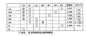
以上のように構成された変速機構10では、例えば、図2の係合作動表に示されるように、前記切換クラッチC0、第1クラッチC1、第2クラッチC2、切換ブレーキB0、第1ブレーキB1、第2ブレーキB2、および第3ブレーキB3が選択的に係合作動させられることにより、第1速ギヤ段(第1変速段)乃至第5速ギヤ段(第5変速段)のいずれか或いは後進ギヤ段(後進変速段)或いはニュートラルが選択的に成立させられ、略等比的に変化する変速比γ(=入力軸回転速度NIN/出力軸回転速度NOUT)が各ギヤ段毎に得られるようになっている。特に、本実施例では動力分配機構16に切換クラッチC0および切換ブレーキB0が備えられており、切換クラッチC0および切換ブレーキB0の何れかが係合作動させられることによって、差動部11は前述した無段変速機として作動する無段変速状態に加え、変速比が一定の変速機として作動する定変速状態を構成することが可能とされている。したがって、変速機構10では、切換クラッチC0および切換ブレーキB0の何れかを係合作動させることで定変速状態とされた差動部11と自動変速部20とで有段変速機として作動する有段変速状態が構成され、切換クラッチC0および切換ブレーキB0の何れも係合作動させないことで無段変速状態とされた差動部11と自動変速部20とで電気的な無段変速機として作動する無段変速状態が構成される。言い換えれば、変速機構10は、切換クラッチC0および切換ブレーキB0の何れかを係合作動させることで有段変速状態に切り換えられ、切換クラッチC0および切換ブレーキB0の何れも係合作動させないことで無段変速状態に切り換えられる。また、差動部11も有段変速状態と無段変速状態とに切り換え可能な変速機であると言える。 In the speed change mechanism 10 configured as described above, for example, as shown in the engagement operation table of FIG. 2, the switching clutch C0, the first clutch C1, the second clutch C2, the switching brake B0, and the first brake B1. When the second brake B2 and the third brake B3 are selectively engaged, any one of the first gear (first gear) to the fifth gear (fifth gear) or A reverse gear stage (reverse gear stage) or neutral is selectively established, and a gear ratio γ (= input shaft rotational speed N IN / output shaft rotational speed N OUT ) that changes substantially in an equal ratio is determined for each gear stage. It has come to be obtained. In particular, in this embodiment, the power distribution mechanism 16 is provided with a switching clutch C0 and a switching brake B0, and the differential unit 11 is configured as described above when either the switching clutch C0 or the switching brake B0 is engaged. In addition to the continuously variable transmission state that operates as a continuously variable transmission, it is possible to configure a constant transmission state that operates as a transmission having a constant gear ratio. Therefore, in the speed change mechanism 10, the stepped portion that operates as a stepped transmission is constituted by the differential portion 11 and the automatic speed change portion 20 that are brought into a constant speed change state by engaging and operating either the switching clutch C0 or the switching brake B0. A speed change state is configured, and the differential part 11 and the automatic speed change part 20 which are brought into a continuously variable transmission state by operating neither the switching clutch C0 nor the switching brake B0 operate as an electric continuously variable transmission. A continuously variable transmission state is configured. In other words, the speed change mechanism 10 is switched to the stepped speed change state by engaging either the switching clutch C0 or the switching brake B0, and is not operated by engaging any of the switching clutch C0 or the switching brake B0. It is switched to the step shifting state. Further, it can be said that the differential unit 11 is also a transmission that can be switched between a stepped transmission state and a continuously variable transmission state.

例えば、変速機構10が有段変速機として機能する場合には、図2に示すように、切換クラッチC0、第1クラッチC1および第3ブレーキB3の係合により、変速比γ1が最大値例えば「3.357」程度である第1速ギヤ段が成立させられ、切換クラッチC0、第1クラッチC1および第2ブレーキB2の係合により、変速比γ2が第1速ギヤ段よりも小さい値例えば「2.180」程度である第2速ギヤ段が成立させられ、切換クラッチC0、第1クラッチC1および第1ブレーキB1の係合により、変速比γ3が第2速ギヤ段よりも小さい値例えば「1.424」程度である第3速ギヤ段が成立させられ、切換クラッチC0、第1クラッチC1および第2クラッチC2の係合により、変速比γ4が第3速ギヤ段よりも小さい値例えば「1.000」程度である第4速ギヤ段が成立させられ、第1クラッチC1、第2クラッチC2、および切換ブレーキB0の係合により、変速比γ5が第4速ギヤ段よりも小さい値例えば「0.705」程度である第5速ギヤ段が成立させられる。また、第2クラッチC2および第3ブレーキB3の係合により、変速比γRが第1速ギヤ段と第2速ギヤ段との間の値例えば「3.209」程度である後進ギヤ段が成立させられる。なお、ニュートラル「N」状態とする場合には、例えば切換クラッチC0のみが係合される。   For example, when the speed change mechanism 10 functions as a stepped transmission, as shown in FIG. 2, the gear ratio γ1 is set to a maximum value, for example, “3” due to the engagement of the switching clutch C0, the first clutch C1, and the third brake B3. The first speed gear stage of about 3.357 "is established, and the gear ratio γ2 is smaller than the first speed gear stage by engagement of the switching clutch C0, the first clutch C1, and the second brake B2, for example,“ The second speed gear stage which is about 2.180 "is established, and the gear ratio γ3 is smaller than the second speed gear stage by engagement of the switching clutch C0, the first clutch C1 and the first brake B1, for example," The third speed gear stage which is about 1.424 "is established, and the gear ratio γ4 is smaller than the third speed gear stage by engagement of the switching clutch C0, the first clutch C1 and the second clutch C2, for example," The fourth speed gear stage that is about .000 "is established, and the engagement of the first clutch C1, the second clutch C2, and the switching brake B0 causes the gear ratio γ5 to be smaller than the fourth speed gear stage, for example," The fifth gear stage which is about 0.705 "is established. Further, by the engagement of the second clutch C2 and the third brake B3, the reverse gear stage in which the speed ratio γR is a value between the first speed gear stage and the second speed gear stage, for example, about “3.209” is established. Be made. When the neutral “N” state is set, for example, only the switching clutch C0 is engaged.

しかし、変速機構10が無段変速機として機能する場合には、図2に示される係合表の切換クラッチC0および切換ブレーキB0が共に解放される。これにより、差動部11が無段変速機として機能し、それに直列の自動変速部20が有段変速機として機能することにより、自動変速部20の第1速、第2速、第3速、第4速の各ギヤ段に対しその自動変速部20に入力される回転速度すなわち伝達部材18の回転速度が無段的に変化させられて各ギヤ段は無段的な変速比幅が得られる。したがって、その各ギヤ段の間が無段的に連続変化可能な変速比となって変速機構10全体としてのトータル変速比(総合変速比)γTが無段階に得られるようになる。   However, when the transmission mechanism 10 functions as a continuously variable transmission, both the switching clutch C0 and the switching brake B0 in the engagement table shown in FIG. 2 are released. Accordingly, the differential unit 11 functions as a continuously variable transmission, and the automatic transmission unit 20 in series with the differential unit 11 functions as a stepped transmission, whereby the first speed, the second speed, and the third speed of the automatic transmission unit 20 are achieved. The rotational speed input to the automatic transmission unit 20, that is, the rotational speed of the transmission member 18 is changed steplessly for each gear stage of the fourth speed, and each gear stage has a stepless speed ratio width. It is done. Therefore, the gear ratio between the gear stages can be continuously changed continuously, and the total speed ratio (total speed ratio) γT of the speed change mechanism 10 as a whole can be obtained steplessly.

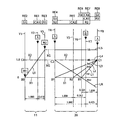
図3は、無段変速部或いは第1変速部として機能する差動部11と有段変速部或いは第2変速部として機能する自動変速部20とから構成される変速機構10において、ギヤ段毎に連結状態が異なる各回転要素の回転速度の相対関係を直線上で表すことができる共線図を示している。この図3の共線図は、各遊星歯車装置24、26、28、30のギヤ比ρの関係を示す横軸と、相対的回転速度を示す縦軸とから成る二次元座標であり、3本の横線のうちの下側の横線X1が回転速度零を示し、上側の横線X2が回転速度「1.0」すなわち入力軸14に連結されたエンジン8の回転速度Nを示し、横線XGが伝達部材18の回転速度を示している。 FIG. 3 is a diagram illustrating a transmission mechanism 10 including a differential unit 11 that functions as a continuously variable transmission unit or a first transmission unit and an automatic transmission unit 20 that functions as a stepped transmission unit or a second transmission unit. The collinear chart which can represent on a straight line the relative relationship of the rotational speed of each rotation element from which a connection state differs is shown. The collinear diagram of FIG. 3 is a two-dimensional coordinate composed of a horizontal axis indicating the relationship of the gear ratio ρ of each planetary gear unit 24, 26, 28, 30 and a vertical axis indicating the relative rotational speed. shows the lower horizontal line X1 rotational speed zero of the horizontal lines, the upper horizontal line X2 the rotational speed of "1.0", that represents the rotational speed N E of the engine 8 connected to the input shaft 14, horizontal line XG Indicates the rotational speed of the transmission member 18.

また、差動部11を構成する動力分配機構16の3つの要素に対応する3本の縦線Y1、Y2、Y3は、左側から順に第2回転要素(第2要素)RE2に対応する第1サンギヤS1、第1回転要素(第1要素)RE1に対応する第1キャリヤCA1、第3回転要素(第3要素)RE3に対応する第1リングギヤR1の相対回転速度を示すものであり、それらの間隔は第1遊星歯車装置24のギヤ比ρ1に応じて定められている。さらに、自動変速部20の5本の縦線Y4、Y5、Y6、Y7、Y8は、左から順に、第4回転要素(第4要素)RE4に対応し且つ相互に連結された第2サンギヤS2および第3サンギヤS3を、第5回転要素(第5要素)RE5に対応する第2キャリヤCA2を、第6回転要素(第6要素)RE6に対応する第4リングギヤR4を、第7回転要素(第7要素)RE7に対応し且つ相互に連結された第2リングギヤR2、第3キャリヤCA3、第4キャリヤCA4を、第8回転要素(第8要素)RE8に対応し且つ相互に連結された第3リングギヤR3、第4サンギヤS4をそれぞれ表し、それらの間隔は第2、第3、第4遊星歯車装置26、28、30のギヤ比ρ2、ρ3、ρ4に応じてそれぞれ定められている。共線図の縦軸間の関係においてサンギヤとキャリヤとの間が「1」に対応する間隔とされるとキャリヤとリングギヤとの間が遊星歯車装置のギヤ比ρに対応する間隔とされる。すなわち、差動部11では縦線Y1とY2との縦線間が「1」に対応する間隔に設定され、縦線Y2とY3との間隔はギヤ比ρ1に対応する間隔に設定される。また、自動変速部20では各第2、第3、第4遊星歯車装置26、28、30毎にそのサンギヤとキャリヤとの間が「1」に対応する間隔に設定され、キャリヤとリングギヤとの間がρに対応する間隔に設定される。   In addition, three vertical lines Y1, Y2, and Y3 corresponding to the three elements of the power distribution mechanism 16 constituting the differential unit 11 are the first corresponding to the second rotation element (second element) RE2 from the left side. The relative rotation speed of the first ring gear R1 corresponding to the sun gear S1, the first rotation element (first element) RE1 corresponding to the first carrier CA1, and the third rotation element (third element) RE3 is shown. The interval is determined according to the gear ratio ρ1 of the first planetary gear device 24. Further, the five vertical lines Y4, Y5, Y6, Y7, Y8 of the automatic transmission unit 20 correspond to the fourth rotation element (fourth element) RE4 and are connected to each other in order from the left. And the third sun gear S3, the second carrier CA2 corresponding to the fifth rotating element (fifth element) RE5, the fourth ring gear R4 corresponding to the sixth rotating element (sixth element) RE6, and the seventh rotating element ( Seventh element) The second ring gear R2, the third carrier CA3, and the fourth carrier CA4 corresponding to RE7 and connected to each other are connected to the eighth rotation element (eighth element) RE8 and connected to each other. The three-ring gear R3 and the fourth sun gear S4 are respectively represented, and the distance between them is determined according to the gear ratios ρ2, ρ3, and ρ4 of the second, third, and fourth planetary gear devices 26, 28, and 30, respectively. In the relationship between the vertical axes of the nomogram, when the distance between the sun gear and the carrier is set to an interval corresponding to “1”, the interval between the carrier and the ring gear is set to an interval corresponding to the gear ratio ρ of the planetary gear device. That is, in the differential unit 11, the interval between the vertical lines Y1 and Y2 is set to an interval corresponding to “1”, and the interval between the vertical lines Y2 and Y3 is set to an interval corresponding to the gear ratio ρ1. Further, in the automatic transmission unit 20, the interval between the sun gear and the carrier is set to an interval corresponding to "1" for each of the second, third, and fourth planetary gear devices 26, 28, and 30, so that the carrier and the ring gear The interval is set to an interval corresponding to ρ.

上記図3の共線図を用いて表現すれば、本実施例の変速機構10は、動力分配機構16(差動部11)において、第1遊星歯車装置24の第1回転要素RE1(第1キャリヤCA1)が入力軸14すなわちエンジン8に連結されるとともに切換クラッチC0を介して第2回転要素(第1サンギヤS1)RE2と選択的に連結され、第2回転要素RE2が第1電動機M1に連結されるとともに切換ブレーキB0を介してケース12に選択的に連結され、第3回転要素(第1リングギヤR1)RE3が伝達部材18および第2電動機M2に連結されて、入力軸14の回転を伝達部材18を介して自動変速部(有段変速部)20へ伝達する(入力させる)ように構成されている。このとき、Y2とX2の交点を通る斜めの直線L0により第1サンギヤS1の回転速度と第1リングギヤR1の回転速度との関係が示される。   If expressed using the collinear diagram of FIG. 3 described above, the speed change mechanism 10 of the present embodiment is configured such that the first rotating element RE1 (the first rotating element RE1) of the first planetary gear device 24 in the power distribution mechanism 16 (the differential unit 11). The carrier CA1) is connected to the input shaft 14, that is, the engine 8, and is selectively connected to the second rotating element (first sun gear S1) RE2 via the switching clutch C0, and the second rotating element RE2 is connected to the first electric motor M1. The third rotary element (first ring gear R1) RE3 is connected to the transmission member 18 and the second electric motor M2 to selectively rotate the input shaft 14 through the switching brake B0. It is configured to transmit (input) to an automatic transmission unit (stepped transmission unit) 20 via a transmission member 18. At this time, the relationship between the rotational speed of the first sun gear S1 and the rotational speed of the first ring gear R1 is indicated by an oblique straight line L0 passing through the intersection of Y2 and X2.

例えば、上記切換クラッチC0および切換ブレーキB0の解放により無段変速状態(差動状態)に切換えられたときは、第1電動機M1の発電による反力を制御することによって直線L0と縦線Y1との交点で示される第1サンギヤS1の回転が上昇或いは下降させられると、直線L0と縦線Y3との交点で示される第1リングギヤR1の回転速度が下降或いは上昇させられる。また、切換クラッチC0の係合により第1サンギヤS1と第1キャリヤCA1とが連結されると、動力分配機構16は上記3回転要素が一体回転する非差動状態とされるので、直線L0は横線X2と一致させられ、エンジン回転速度Nと同じ回転で伝達部材18が回転させられる。或いは、切換ブレーキB0の係合によって第1サンギヤS1の回転が停止させられると動力分配機構16は増速機構として機能する非差動状態とされるので、直線L0は図3に示す状態となり、その直線L0と縦線Y3との交点で示される第1リングギヤR1すなわち伝達部材18の回転速度は、エンジン回転速度Nよりも増速された回転で自動変速部20へ入力される。 For example, when switching to the continuously variable transmission state (differential state) by releasing the switching clutch C0 and the switching brake B0, the reaction force generated by the first motor M1 is controlled to control the straight line L0 and the vertical line Y1. When the rotation of the first sun gear S1 indicated by the intersection point is raised or lowered, the rotational speed of the first ring gear R1 indicated by the intersection point between the straight line L0 and the vertical line Y3 is lowered or raised. Further, when the first sun gear S1 and the first carrier CA1 are connected by the engagement of the switching clutch C0, the power distribution mechanism 16 is brought into a non-differential state in which the three rotating elements rotate integrally, so that the straight line L0 is It is aligned with the horizontal line X2, whereby the power transmitting member 18 is rotated at the same rotation to the engine speed N E. Alternatively, when the rotation of the first sun gear S1 is stopped by the engagement of the switching brake B0, the power distribution mechanism 16 is in a non-differential state that functions as a speed increasing mechanism, so the straight line L0 is in the state shown in FIG. rotational speed of the first ring gear R1, i.e., the power transmitting member 18 represented by a point of intersection between the straight line L0 and the vertical line Y3 is input to the automatic shifting portion 20 at a rotation speed higher than the engine speed N E.

また、自動変速部20において第4回転要素RE4は第2クラッチC2を介して伝達部材18に選択的に連結されるとともに第1ブレーキB1を介してケース12に選択的に連結され、第5回転要素RE5は第2ブレーキB2を介してケース12に選択的に連結され、第6回転要素RE6は第3ブレーキB3を介してケース12に選択的に連結され、第7回転要素RE7は出力軸22に連結され、第8回転要素RE8は第1クラッチC1を介して伝達部材18に選択的に連結されている。   Further, in the automatic transmission unit 20, the fourth rotation element RE4 is selectively connected to the transmission member 18 via the second clutch C2, and is also selectively connected to the case 12 via the first brake B1, for the fifth rotation. The element RE5 is selectively connected to the case 12 via the second brake B2, the sixth rotating element RE6 is selectively connected to the case 12 via the third brake B3, and the seventh rotating element RE7 is connected to the output shaft 22. The eighth rotary element RE8 is selectively connected to the transmission member 18 via the first clutch C1.

自動変速部20では、図3に示すように、第1クラッチC1と第3ブレーキB3とが係合させられることにより、第8回転要素RE8の回転速度を示す縦線Y8と横線X2との交点と第6回転要素RE6の回転速度を示す縦線Y6と横線X1との交点とを通る斜めの直線L1と、出力軸22と連結された第7回転要素RE7の回転速度を示す縦線Y7との交点で第1速の出力軸22の回転速度が示される。同様に、第1クラッチC1と第2ブレーキB2とが係合させられることにより決まる斜めの直線L2と出力軸22と連結された第7回転要素RE7の回転速度を示す縦線Y7との交点で第2速の出力軸22の回転速度が示され、第1クラッチC1と第1ブレーキB1とが係合させられることにより決まる斜めの直線L3と出力軸22と連結された第7回転要素RE7の回転速度を示す縦線Y7との交点で第3速の出力軸22の回転速度が示され、第1クラッチC1と第2クラッチC2とが係合させられることにより決まる水平な直線L4と出力軸22と連結された第7回転要素RE7の回転速度を示す縦線Y7との交点で第4速の出力軸22の回転速度が示される。上記第1速乃至第4速では、切換クラッチC0が係合させられている結果、エンジン回転速度Nと同じ回転速度で第8回転要素RE8に差動部11すなわち動力分配機構16からの動力が入力される。しかし、切換クラッチC0に替えて切換ブレーキB0が係合させられると、差動部11からの動力がエンジン回転速度Nよりも高い回転速度で入力されることから、第1クラッチC1、第2クラッチC2、および切換ブレーキB0が係合させられることにより決まる水平な直線L5と出力軸22と連結された第7回転要素RE7の回転速度を示す縦線Y7との交点で第5速の出力軸22の回転速度が示される。 In the automatic transmission unit 20, as shown in FIG. 3, when the first clutch C1 and the third brake B3 are engaged, the intersection of the vertical line Y8 indicating the rotational speed of the eighth rotation element RE8 and the horizontal line X2 And an oblique straight line L1 passing through the intersection of the vertical line Y6 indicating the rotational speed of the sixth rotational element RE6 and the horizontal line X1, and a vertical line Y7 indicating the rotational speed of the seventh rotational element RE7 connected to the output shaft 22. The rotational speed of the output shaft 22 of the first speed is shown at the intersection point. Similarly, at an intersection of an oblique straight line L2 determined by engaging the first clutch C1 and the second brake B2 and a vertical line Y7 indicating the rotational speed of the seventh rotating element RE7 connected to the output shaft 22. The rotational speed of the output shaft 22 at the second speed is shown, and an oblique straight line L3 determined by engaging the first clutch C1 and the first brake B1 and the seventh rotational element RE7 connected to the output shaft 22 The rotation speed of the output shaft 22 of the third speed is indicated by the intersection with the vertical line Y7 indicating the rotation speed, and the horizontal straight line L4 and the output shaft determined by engaging the first clutch C1 and the second clutch C2. The rotation speed of the output shaft 22 of the fourth speed is indicated by the intersection with the vertical line Y7 indicating the rotation speed of the seventh rotation element RE7 connected to the motor 22. Power from the aforementioned first speed through the fourth speed, as a result of the switching clutch C0 is engaged, the eighth rotary element RE8 differential portion 11 or power distributing mechanism 16 in the same rotational speed as the engine speed N E Is entered. However, when the switching brake B0 in place of the switching clutch C0 is engaged, the drive force received from the differential portion 11 is input at a higher speed than the engine rotational speed N E, first clutch C1, second The output shaft of the fifth speed at the intersection of the horizontal straight line L5 determined by engaging the clutch C2 and the switching brake B0 and the vertical line Y7 indicating the rotational speed of the seventh rotation element RE7 connected to the output shaft 22 A rotational speed of 22 is indicated.

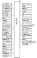
図4は、本実施例の変速機構10を制御するための電子制御装置40に入力される信号及びその電子制御装置40から出力される信号を例示している。この電子制御装置40は、CPU、ROM、RAM、及び入出力インターフェースなどから成る所謂マイクロコンピュータを含んで構成されており、RAMの一時記憶機能を利用しつつROMに予め記憶されたプログラムに従って信号処理を行うことによりエンジン8、第1、第2電動機M1、M2に関するハイブリッド駆動制御、自動変速部20の変速制御等の駆動制御を実行するものである。   FIG. 4 illustrates a signal input to the electronic control device 40 for controlling the speed change mechanism 10 of the present embodiment and a signal output from the electronic control device 40. The electronic control unit 40 includes a so-called microcomputer including a CPU, a ROM, a RAM, an input / output interface, and the like, and performs signal processing according to a program stored in advance in the ROM while using a temporary storage function of the RAM. By performing the above, drive control such as hybrid drive control relating to the engine 8, the first and second electric motors M1 and M2, and the shift control of the automatic transmission 20 is executed.

電子制御装置40には、図4に示す各センサやスイッチから、エンジン水温TEMPを示す信号、シフトポジションPSHを表す信号、エンジン8の回転速度であるエンジン回転速度Nを表す信号、ギヤ比列設定値を示す信号、M(モータ走行)モードを指令する信号、エアコンの作動を示すエアコン信号、出力軸22の回転速度NOUTに対応する車速Vを表す信号、自動変速部20の作動油温を示す油温信号、サイドブレーキ操作を示す信号、フットブレーキ操作を示す信号、触媒温度を示す触媒温度信号、アクセルペダル操作量Accを示すアクセル開度信号、カム角信号、スノーモード設定を示すスノーモード設定信号、車両の前後加速度を示す加速度信号、オートクルーズ走行を示すオートクルーズ信号、車両の重量を示す車重信号、各駆動輪の車輪速を示す車輪速信号、変速機構10を有段変速機として機能させるために差動部11(動力分配機構16)を有段変速状態(ロック状態)に切り換えるための有段スイッチ操作の有無を示す信号、変速機構10を無段変速機として機能させるために差動部11(動力分配機構16)を無段変速状態(差動状態)に切り換えるための無段スイッチ操作の有無を示す信号、第1電動機M1の回転速度NM1(以下、第1電動機回転速度NM1という)を表す信号、第2電動機M2の回転速度NM2(以下、第2電動機回転速度NM2という)を表す信号などが、それぞれ供給される。 The electronic control unit 40, from the sensors and switches shown in FIG. 4, a signal representative of the signal indicative of the engine coolant temperature TEMP W, the signal representing the shift position P SH, the engine rotational speed N E is the rotational speed of the engine 8, the gear A signal indicating a ratio set value, a signal for instructing an M (motor running) mode, an air conditioner signal indicating the operation of an air conditioner, a signal indicating a vehicle speed V corresponding to the rotational speed N OUT of the output shaft 22, and an operation of the automatic transmission unit 20 Oil temperature signal indicating oil temperature, signal indicating side brake operation, signal indicating foot brake operation, catalyst temperature signal indicating catalyst temperature, accelerator opening signal indicating accelerator pedal operation amount Acc, cam angle signal, snow mode setting Snow mode setting signal indicating, acceleration signal indicating vehicle longitudinal acceleration, auto cruise signal indicating auto cruise driving, vehicle indicating vehicle weight Signal, wheel speed signal indicating the wheel speed of each drive wheel, and for switching the differential unit 11 (power distribution mechanism 16) to a stepped shift state (lock state) in order to cause the transmission mechanism 10 to function as a stepped transmission. A signal indicating whether or not a stepped switch is operated, a continuously variable switch for switching the differential unit 11 (power distribution mechanism 16) to a continuously variable transmission state (differential state) in order to cause the transmission mechanism 10 to function as a continuously variable transmission. A signal indicating the presence / absence of an operation, a signal indicating the rotation speed N M1 of the first motor M1 (hereinafter referred to as the first motor rotation speed N M1 ), a rotation speed N M2 of the second motor M2 (hereinafter referred to as the second motor rotation speed N) M2 ) and the like are supplied respectively.

また、上記電子制御装置40からは、エンジン出力を制御するエンジン出力制御装置43(図5参照)への制御信号例えばエンジン8の吸気管95に備えられた電子スロットル弁96の開度を操作するスロットルアクチュエータ97への駆動信号や燃料噴射装置98による上記吸気管95或いはエンジン8の筒内への燃料供給量を制御する燃料供給量信号や点火装置99によるエンジン8の点火時期を指令する点火信号、過給圧を調整するための過給圧調整信号、電動エアコンを作動させるための電動エアコン駆動信号、電動機M1およびM2の作動を指令する指令信号、シフトインジケータを作動させるためのシフトポジション(操作位置)表示信号、ギヤ比を表示させるためのギヤ比表示信号、スノーモードであることを表示させるためのスノーモード表示信号、制動時の車輪のスリップを防止するABSアクチュエータを作動させるためのABS作動信号、Mモードが選択されていることを表示させるMモード表示信号、差動部11や自動変速部20の油圧式摩擦係合装置の油圧アクチュエータを制御するために油圧制御回路42に含まれる電磁弁を作動させるバルブ指令信号、上記油圧制御回路42(図5参照)の油圧源である電動油圧ポンプを作動させるための駆動指令信号、電動ヒータを駆動するための信号、クルーズコントロール制御用コンピュータへの信号等が、それぞれ出力される。   Further, the electronic control device 40 operates a control signal to the engine output control device 43 (see FIG. 5) for controlling the engine output, for example, the opening degree of the electronic throttle valve 96 provided in the intake pipe 95 of the engine 8. A drive signal to the throttle actuator 97, a fuel supply amount signal for controlling the fuel supply amount to the intake pipe 95 or the cylinder of the engine 8 by the fuel injection device 98, and an ignition signal for instructing the ignition timing of the engine 8 by the ignition device 99 , A supercharging pressure adjustment signal for adjusting the supercharging pressure, an electric air conditioner drive signal for operating the electric air conditioner, a command signal for instructing the operation of the electric motors M1 and M2, and a shift position (operation for operating the shift indicator) Position) Display signal, Gear ratio display signal for displaying gear ratio, To display that it is in snow mode Snow mode display signal, ABS operation signal for operating an ABS actuator that prevents slipping of the wheel during braking, M mode display signal for indicating that the M mode is selected, the differential unit 11 and the automatic transmission unit 20 A valve command signal for operating a solenoid valve included in the hydraulic control circuit 42 to control the hydraulic actuator of the hydraulic friction engagement device, and an electric hydraulic pump as a hydraulic source of the hydraulic control circuit 42 (see FIG. 5). A drive command signal for operating, a signal for driving the electric heater, a signal to the cruise control control computer, and the like are output.

図5は、電子制御装置40による制御機能の要部を説明する機能ブロック線図である。図5において、有段変速制御手段54は、例えば記憶手段56に予め記憶された図6の実線および一点鎖線に示す変速線図(変速マップ)から車速Vおよび自動変速部20の要求出力トルクTOUTで示される車両状態に基づいて変速機構10の変速を実行すべきか否かを判断してすなわち変速機構10の変速すべき変速段を判断して自動変速部20の自動変速制御を実行する。例えば、有段変速制御手段54は、図2に示す係合表に従って変速段が達成されるように切換クラッチC0および切換ブレーキB0を除いた油圧式摩擦係合装置を係合および/または解放させる指令を油圧制御回路42へ出力する。 FIG. 5 is a functional block diagram for explaining a main part of the control function by the electronic control unit 40. In FIG. 5, the stepped speed change control means 54 is, for example, a vehicle speed V and a required output torque T of the automatic speed changer 20 from a speed change diagram (speed change map) indicated by a solid line and a dashed line in FIG. Based on the vehicle state indicated by OUT , it is determined whether or not the speed change of the speed change mechanism 10 should be executed, that is, the speed change stage of the speed change mechanism 10 is determined, and the automatic speed change control of the automatic speed change unit 20 is executed. For example, the stepped shift control means 54 engages and / or releases the hydraulic friction engagement device excluding the switching clutch C0 and the switching brake B0 so that the shift stage is achieved according to the engagement table shown in FIG. The command is output to the hydraulic control circuit 42.

ハイブリッド制御手段52は、変速機構10の前記無段変速状態すなわち差動部11の差動状態においてエンジン8を効率のよい作動域で作動させる一方で、エンジン8と第2電動機M2との駆動力の配分や第1電動機M1の発電による反力を最適になるように変化させて差動部11の電気的な無段変速機としての変速比γ0を制御する。例えば、そのときの走行車速において、運転者の出力要求量としてのアクセルペダル操作量Accや車速Vから車両の目標(要求)出力を算出し、車両の目標出力と充電要求値から必要なトータル目標出力を算出し、そのトータル目標出力が得られるように伝達損失、補機負荷、第2電動機M2のアシストトルク等を考慮して目標エンジン出力を算出し、その目標エンジン出力が得られるエンジン回転速度NとエンジントルクTとなるようにエンジン8を制御するとともに第1電動機M1の発電量を制御する。言い換えれば、ハイブリッド制御手段52は同じ車速および同じ自動変速部20のギヤ比すなわち伝達部材18の回転速度が同じであっても、第1電動機M1の発電量を制御することでエンジン回転速度Nを制御することが可能である。 The hybrid control means 52 operates the engine 8 in an efficient operating range in the continuously variable transmission state of the transmission mechanism 10, that is, the differential state of the differential unit 11, while driving force between the engine 8 and the second electric motor M2. The transmission ratio γ0 of the differential unit 11 as an electric continuously variable transmission is controlled by changing the distribution of the power and the reaction force generated by the first electric motor M1 so as to be optimized. For example, at the current traveling vehicle speed, the vehicle target (request) output is calculated from the accelerator pedal operation amount Acc as the driver's required output amount and the vehicle speed V, and the required total target is calculated from the vehicle target output and the charge request value. The engine speed is calculated by calculating the target engine output in consideration of transmission loss, auxiliary load, assist torque of the second electric motor M2, etc. so as to obtain the total target output. The engine 8 is controlled so that N E and the engine torque T E are obtained, and the power generation amount of the first electric motor M1 is controlled. In other words, the hybrid control means 52 be a rotational speed of the gear ratio, i.e., the power transmitting member 18 of the same vehicle speed and the same automatic shifting portion 20 are the same, the engine rotational speed N E by controlling the amount of power generated by the first electric motor M1 Can be controlled.

ハイブリッド制御手段52は、その制御を動力性能や燃費向上などのために自動変速部20の変速段を考慮して実行する。このようなハイブリッド制御では、エンジン8を効率のよい作動域で作動させるために定まるエンジン回転速度Nと車速Vおよび自動変速部20の変速段で定まる伝達部材18の回転速度とを整合させるために、差動部11が電気的な無段変速機として機能させられる。すなわち、ハイブリッド制御手段52は例えばエンジン回転速度Nとエンジン8の出力トルク(エンジントルク)Tとをパラメータとする二次元座標内において無段変速走行の時に運転性と燃費性とを両立するように予め実験的に定められたエンジン8の最適燃費率曲線(燃費マップ、関係)を予め記憶しており、その最適燃費率曲線に沿ってエンジン8が作動させられるように、例えば目標出力(トータル目標出力、要求駆動力)を充足するために必要なエンジン出力を発生するためのエンジントルクTとエンジン回転速度Nとなるように変速機構10のトータル変速比γTの目標値を定め、その目標値が得られるように差動部11の変速比γ0を制御し、トータル変速比γTをその変速可能な変化範囲内例えば13〜0.5の範囲内で制御する。 The hybrid control means 52 executes the control in consideration of the gear position of the automatic transmission unit 20 for improving power performance and fuel consumption. In such a hybrid control for matching the rotational speed of the power transmitting member 18 determined by the gear position of the engine rotational speed N E and the vehicle speed V and the automatic transmission portion 20 determined to operate the engine 8 in an operating region at efficient Further, the differential unit 11 is caused to function as an electric continuously variable transmission. That is, the hybrid control means 52 to achieve both the drivability and the fuel consumption when the continuously-variable shifting control in a two-dimensional coordinate system defined by control parameters and output torque (engine torque) T E of example the engine rotational speed N E and the engine 8 Thus, an optimum fuel consumption rate curve (fuel consumption map, relationship) of the engine 8 determined experimentally in advance is stored in advance and, for example, a target output ( total target output, determines the target value of the overall speed ratio γT of the transmission mechanism 10 such that the engine torque T E and the engine rotational speed N E for generating the engine output necessary to meet the required driving force), The speed ratio γ0 of the differential unit 11 is controlled so that the target value is obtained, and the total speed ratio γT is set within a changeable range of the speed change, for example, 13 to 0.5. Control within the enclosure.

このとき、ハイブリッド制御手段52は、第1電動機M1により発電された電気エネルギをインバータ58を通して蓄電装置60や第2電動機M2へ供給するので、エンジン8の動力の主要部は機械的に伝達部材18へ伝達されるが、エンジン8の動力の一部は第1電動機M1の発電のために消費されてそこで電気エネルギに変換され、インバータ58を通して電気エネルギが第2電動機M2へ供給され、その第2電動機M2が駆動されて第2電動機M2から伝達部材18へ伝達される。この電気エネルギの発生から第2電動機M2で消費されるまでに関連する機器により、エンジン8の動力の一部を電気エネルギに変換し、その電気エネルギを機械的エネルギに変換するまでの電気パスが構成される。   At this time, the hybrid control means 52 supplies the electric energy generated by the first electric motor M1 to the power storage device 60 and the second electric motor M2 through the inverter 58, so that the main part of the power of the engine 8 is mechanically transmitted to the transmission member 18. However, part of the motive power of the engine 8 is consumed for power generation of the first electric motor M1 and converted there to electric energy, and electric energy is supplied to the second electric motor M2 through the inverter 58, and the second The electric motor M2 is driven and transmitted from the second electric motor M2 to the transmission member 18. An electric path from conversion of a part of the power of the engine 8 into electric energy and conversion of the electric energy into mechanical energy by a device related from the generation of the electric energy to consumption by the second electric motor M2 Composed.

また、ハイブリッド制御手段52は、エンジン8の作動停止状態であっても差動部11の電気的CVT機能(差動作用)によって電動機のみ例えば第2電動機M2のみを走行用の駆動力源として車両を発進および走行させる所謂モータ発進およびモータ走行させることができる。上記モータ発進時およびモータ走行時には、ハイブリッド制御手段52は、作動していないエンジン8の引き摺りを抑制して燃費を向上させるために、第1電動機回転速度NM1を負の回転速度で制御例えば空転させて差動部11の差動作用によりエンジン回転速度Nが零乃至略零に維持される。ハイブリッド制御手段52によるモータ発進およびモータ走行は、一般的にエンジン効率が高トルク域に比較して悪いとされる比較的低出力トルクTOUT時すなわち低エンジントルクT時、或いは車速Vの比較的低車速時すなわち低負荷域で実行される。 Further, even when the engine 8 is in an operation stop state, the hybrid control means 52 uses the electric CVT function (differential action) of the differential portion 11 as a driving power source for traveling, using only the electric motor, for example, only the second electric motor M2. So-called motor starting and motor driving can be performed. When the motor is started and the motor is running, the hybrid control means 52 controls the first motor rotation speed N M1 at a negative rotation speed in order to suppress dragging of the engine 8 that is not operating and improve fuel efficiency, for example, idling. engine rotational speed N E is maintained at zero or substantially zero by the differential action of the differential portion 11 by. The motor start and the motor running by the hybrid control means 52 are generally compared at the time of a relatively low output torque T OUT , that is, at a low engine torque T E , or at a vehicle speed V, where the engine efficiency is poor compared to the high torque range. It is executed at low vehicle speed, that is, in a low load range.

また、ハイブリッド制御手段52は、車両の停止状態又は低車速状態に拘わらず、差動部11の電気的CVT機能によってエンジン8の作動状態を維持させられる。例えば、車両停止時に蓄電装置60の充電容量SOCが低下して第1電動機M1による発電が必要となった場合には、エンジン8の動力により第1電動機M1が発電させられてその第1電動機M1の回転速度が引き上げられ、車速Vで一意的に決められる第2電動機回転速度NM2が車両停止状態により零(略零)となっても動力分配機構16の差動作用によってエンジン回転速度Nが自律回転可能な回転速度以上に維持される。 Further, the hybrid control means 52 can maintain the operating state of the engine 8 by the electric CVT function of the differential section 11 regardless of whether the vehicle is stopped or at a low vehicle speed. For example, when the charging capacity SOC of the power storage device 60 is reduced when the vehicle is stopped and the first motor M1 needs to generate power, the first motor M1 is generated by the power of the engine 8, and the first motor M1 is generated. Even if the second motor rotation speed N M2 uniquely determined by the vehicle speed V becomes zero (substantially zero) due to the vehicle stop state, the engine rotation speed N E is caused by the differential action of the power distribution mechanism 16. Is maintained at a speed higher than the autonomous rotation speed.

また、ハイブリッド制御手段52は、車両の停止中又は走行中に拘わらず、差動部11の電気的CVT機能によって第1電動機回転速度NM1および/または第2電動機回転速度NM2を制御してエンジン回転速度Nを任意の回転速度に維持させられる。例えば、図3の共線図からもわかるようにハイブリッド制御手段52はエンジン回転速度Nを引き上げる場合には、車速Vに拘束される第2電動機回転速度NM2を略一定に維持しつつ第1電動機回転速度NM1の引き上げを実行する。 Further, the hybrid control means 52 controls the first motor rotation speed N M1 and / or the second motor rotation speed N M2 by the electric CVT function of the differential section 11 regardless of whether the vehicle is stopped or traveling. the engine rotational speed N E is caused to maintain the arbitrary rotation speed. For example, if the hybrid control means 52 as can be seen from the diagram of FIG. 3 to raise the engine rotational speed N E, while maintaining the second-motor rotation speed N M2, bound with the vehicle speed V substantially constant first 1 Increase the motor rotation speed NM1 .

また、ハイブリッド制御手段52は、蓄電装置60からインバータ58を介して供給される第1電動機M1および第2電動機M2への駆動電流を遮断して第1電動機M1および第2電動機M2を無負荷状態とする。第1電動機M1および第2電動機M2は無負荷状態とされると自由回転することすなわち空転することが許容され、差動部11はトルクの伝達が不能な状態すなわち差動部11内の動力伝達経路が遮断された状態と同等の状態とされる。すなわち、ハイブリッド制御手段52は、第1電動機M1および第2電動機M2を無負荷状態とすることにより差動部11をその動力伝達経路が電気的に遮断される中立状態(ニュートラル状態)とする。   Moreover, the hybrid control means 52 interrupts the drive current to the 1st electric motor M1 and the 2nd electric motor M2 which are supplied via the inverter 58 from the electrical storage apparatus 60, and makes the 1st electric motor M1 and the 2nd electric motor M2 into a no-load state And The first electric motor M1 and the second electric motor M2 are allowed to freely rotate, that is, idle, when in a no-load state, and the differential unit 11 is in a state where torque cannot be transmitted, that is, power transmission in the differential unit 11 The state is equivalent to the state where the route is blocked. That is, the hybrid control means 52 sets the differential unit 11 to a neutral state (neutral state) in which the power transmission path is electrically cut off by setting the first electric motor M1 and the second electric motor M2 to a no-load state.

増速側ギヤ段判定手段62は、変速機構10を有段変速状態とする際に切換クラッチC0および切換ブレーキB0のいずれを係合させるかを判定するために、例えば車両状態に基づいて記憶手段56に予め記憶された前記図6に示す変速線図に従って変速機構10の変速されるべき変速段が増速側ギヤ段例えば第5速ギヤ段であるか否かを判定する。   The speed-increasing gear stage determining means 62 stores, for example, a storage means based on the vehicle state in order to determine which of the switching clutch C0 and the switching brake B0 is engaged when the transmission mechanism 10 is in the stepped speed change state. In accordance with the shift diagram shown in FIG. 6 stored in advance in FIG. 56, it is determined whether or not the gear position to be shifted of the transmission mechanism 10 is the speed increasing side gear stage, for example, the fifth speed gear stage.

切換制御手段50は、例えば記憶手段56に予め記憶された前記図6の破線および二点鎖線に示す切換線図(切換マップ、関係)から車速Vおよび要求出力トルクTOUTで示される車両状態に基づいて変速機構10の変速状態を切り換えるべきか否かを判断してすなわち変速機構10を無段変速状態とする無段制御領域内であるか或いは変速機構10を有段変速状態とする有段制御領域内であるかを判定することにより変速機構10の切り換えるべき変速状態を判断して、変速機構10を前記無段変速状態と前記有段変速状態とのいずれかに選択的に切り換える。 The switching control means 50 changes to the vehicle state indicated by the vehicle speed V and the required output torque T OUT from the switching diagram (switching map, relationship) indicated by the broken line and the two-dot chain line in FIG. On the basis of this, it is determined whether or not the speed change state of the speed change mechanism 10 should be switched, that is, the speed change mechanism 10 is in a stepless control region where the speed change mechanism 10 is set to a stepless speed change state, or By determining whether it is within the control region, the shift state of the transmission mechanism 10 to be switched is determined, and the transmission mechanism 10 is selectively switched between the continuously variable transmission state and the stepped transmission state.

具体的には、切換制御手段50は有段変速制御領域内であると判定した場合は、ハイブリッド制御手段52に対してハイブリッド制御或いは無段変速制御を不許可すなわち禁止とする信号を出力するとともに、有段変速制御手段54に対しては、予め設定された有段変速時の変速制御を許可する。このときの有段変速制御手段54は、記憶手段56に予め記憶された例えば図6に示す変速線図に従って自動変速部20の自動変速制御を実行する。例えば記憶手段56に予め記憶された図2は、このときの変速制御において選択される油圧式摩擦係合装置すなわちC0、C1、C2、B0、B1、B2、B3の作動の組み合わせを示している。すなわち、変速機構10全体すなわち差動部11および自動変速部20が所謂有段式自動変速機として機能し、図2に示す係合表に従って変速段が達成される。   Specifically, when it is determined that the switching control means 50 is within the stepped shift control region, the hybrid control means 52 outputs a signal that disables or prohibits the hybrid control or continuously variable shift control. The step-variable shift control means 54 is permitted to perform shift control at the time of a step-variable shift set in advance. At this time, the stepped shift control means 54 executes automatic shift control of the automatic transmission unit 20 in accordance with, for example, the shift diagram shown in FIG. For example, FIG. 2 stored in advance in the storage means 56 shows a combination of operations of the hydraulic friction engagement devices selected in the speed change control, that is, C0, C1, C2, B0, B1, B2, and B3. . That is, the transmission mechanism 10 as a whole, that is, the differential unit 11 and the automatic transmission unit 20 function as a so-called stepped automatic transmission, and the gear stage is achieved according to the engagement table shown in FIG.

例えば、増速側ギヤ段判定手段62により第5速ギヤ段が判定される場合には、変速機構10全体として変速比が1.0より小さな増速側ギヤ段所謂オーバードライブギヤ段が得られるために切換制御手段50は差動部11が固定の変速比γ0例えば変速比γ0が0.7の副変速機として機能させられるように切換クラッチC0を解放させ且つ切換ブレーキB0を係合させる指令を油圧制御回路42へ出力する。また、増速側ギヤ段判定手段62により第5速ギヤ段でないと判定される場合には、変速機構10全体として変速比が1.0以上の減速側ギヤ段が得られるために切換制御手段50は差動部11が固定の変速比γ0例えば変速比γ0が1の副変速機として機能させられるように切換クラッチC0を係合させ且つ切換ブレーキB0を解放させる指令を油圧制御回路42へ出力する。このように、切換制御手段50によって変速機構10が有段変速状態に切り換えられるとともに、その有段変速状態における2種類の変速段のいずれかとなるように選択的に切り換えられて、差動部11が副変速機として機能させられ、それに直列の自動変速部20が有段変速機として機能することにより、変速機構10全体が所謂有段式自動変速機として機能させられる。   For example, when the fifth gear is determined by the acceleration-side gear determination means 62, the so-called overdrive gear that has a gear ratio smaller than 1.0 is obtained for the entire transmission mechanism 10. Therefore, the switching control means 50 instructs the differential unit 11 to release the switching clutch C0 and engage the switching brake B0 so that the differential unit 11 can function as a sub-transmission with a fixed gear ratio γ0, for example, a gear ratio γ0 of 0.7. Is output to the hydraulic control circuit 42. Further, when it is determined by the acceleration side gear stage determination means 62 that the gear ratio is not the fifth speed gear stage, the speed change gear 10 as a whole can obtain a reduction side gear stage having a gear ratio of 1.0 or more, so that the switching control means. 50 indicates a command to the hydraulic control circuit 42 to engage the switching clutch C0 and release the switching brake B0 so that the differential unit 11 can function as a sub-transmission with a fixed gear ratio γ0, for example, a gear ratio γ0 of 1. To do. In this manner, the transmission mechanism 10 is switched to the stepped speed change state by the switching control means 50 and is selectively switched to be one of the two types of speed steps in the stepped speed change state. Is made to function as a sub-transmission, and the automatic transmission unit 20 in series functions as a stepped transmission, whereby the entire transmission mechanism 10 is made to function as a so-called stepped automatic transmission.

しかし、切換制御手段50は、変速機構10を無段変速状態に切り換える無段変速制御領域内であると判定した場合は、変速機構10全体として無段変速状態が得られるために差動部11を無段変速状態として無段変速可能とするように切換クラッチC0および切換ブレーキB0を解放させる指令を油圧制御回路42へ出力する。同時に、ハイブリッド制御手段52に対してハイブリッド制御を許可する信号を出力するとともに、有段変速制御手段54には、予め設定された無段変速時の変速段に固定する信号を出力するか、或いは記憶手段56に予め記憶された例えば図6に示す変速線図に従って自動変速部20を自動変速することを許可する信号を出力する。この場合、有段変速制御手段54により、図2の係合表内において切換クラッチC0および切換ブレーキB0の係合を除いた作動により自動変速が行われる。このように、切換制御手段50により無段変速状態に切り換えられた差動部11が無段変速機として機能し、それに直列の自動変速部20が有段変速機として機能することにより、適切な大きさの駆動力が得られると同時に、自動変速部20の第1速、第2速、第3速、第4速の各ギヤ段に対しその自動変速部20に入力される回転速度すなわち伝達部材18の回転速度が無段的に変化させられて各ギヤ段は無段的な変速比幅が得られる。したがって、その各ギヤ段の間が無段的に連続変化可能な変速比となって変速機構10全体として無段変速状態となりトータル変速比γTが無段階に得られるようになる。   However, if the switching control means 50 determines that it is within the continuously variable transmission control region for switching the transmission mechanism 10 to the continuously variable transmission state, the transmission mechanism 10 as a whole can obtain the continuously variable transmission state, so that the differential section 11. Is output to the hydraulic control circuit 42 so as to release the switching clutch C0 and the switching brake B0 so that the continuously variable transmission can be performed. At the same time, a signal for permitting hybrid control is output to the hybrid control means 52, and a signal for fixing to a preset gear position at the time of continuously variable transmission is output to the stepped shift control means 54, or For example, a signal for permitting automatic shifting of the automatic transmission unit 20 is output in accordance with the shift diagram shown in FIG. In this case, the stepped shift control means 54 performs an automatic shift by an operation excluding the engagement of the switching clutch C0 and the switching brake B0 in the engagement table of FIG. Thus, the differential unit 11 switched to the continuously variable transmission state by the switching control means 50 functions as a continuously variable transmission, and the automatic transmission unit 20 in series with the differential unit 11 functions as a stepped transmission. At the same time that a large driving force is obtained, the rotational speed input to the automatic transmission unit 20 for each of the first speed, the second speed, the third speed, and the fourth speed of the automatic transmission unit 20, that is, transmission The rotational speed of the member 18 is changed steplessly, and each gear stage can obtain a stepless speed ratio width. Therefore, the gear ratio between the gear stages can be continuously changed continuously and the transmission mechanism 10 as a whole is in a continuously variable transmission state, and the total gear ratio γT can be obtained continuously.

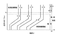
ここで前記図6について詳述すると、図6は自動変速部20の変速判断の基となる記憶手段56に予め記憶された変速線図(変速マップ、関係)であり、車速Vと駆動力関連値である要求出力トルクTOUTとをパラメータとする二次元座標で構成された変速線図の一例である。図6の実線はアップシフト線であり一点鎖線はダウンシフト線である。また、図6の破線は切換制御手段50による有段制御領域と無段制御領域との判定のための判定車速V1および判定出力トルクT1を示している。つまり、図6の破線はハイブリッド車両の高速走行を判定するための予め設定された高速走行判定値である判定車速V1の連なりである高車速判定線と、ハイブリッド車両の駆動力に関連する駆動力関連値例えば自動変速部20の出力トルクTOUTが高出力となる高出力走行を判定するための予め設定された高出力走行判定値である判定出力トルクT1の連なりである高出力走行判定線とを示している。さらに、図6の破線に対して二点鎖線に示すように有段制御領域と無段制御領域との判定にヒステリシスが設けられている。つまり、この図6は判定車速V1および判定出力トルクT1を含む、車速Vと出力トルクTOUTとをパラメータとして切換制御手段50により有段制御領域と無段制御領域とのいずれであるかを領域判定するための予め記憶された切換線図(切換マップ、関係)である。なお、この切換線図を含めて変速マップとして記憶手段56に予め記憶されてもよい。また、この切換線図は判定車速V1および判定出力トルクT1の少なくとも1つを含むものであってもよいし、車速Vおよび出力トルクTOUTの何れかをパラメータとする予め記憶された切換線であってもよい。 6 will be described in detail. FIG. 6 is a shift diagram (shift map, relationship) stored in advance in the storage means 56 that is a basis for shift determination of the automatic transmission unit 20, and relates to the vehicle speed V and the driving force. FIG. 5 is an example of a shift diagram composed of two-dimensional coordinates using a required output torque T OUT as a parameter. The solid line in FIG. 6 is an upshift line, and the alternate long and short dash line is a downshift line. 6 indicates the determination vehicle speed V1 and the determination output torque T1 for determining the stepped control region and the stepless control region by the switching control means 50. That is, the broken line in FIG. 6 indicates a high vehicle speed determination line that is a series of determination vehicle speeds V1 that are preset high-speed traveling determination values for determining high-speed traveling of the hybrid vehicle, and a driving force related to the driving force of the hybrid vehicle. For example, a high output travel determination line that is a series of determination output torque T1 that is a preset high output travel determination value for determining high output travel in which the output torque T OUT of the automatic transmission unit 20 is high output. Is shown. Further, as indicated by a two-dot chain line with respect to the broken line in FIG. 6, hysteresis is provided for the determination of the stepped control region and the stepless control region. In other words, the area or FIG. 6 includes a vehicle-speed limit V1 and the upper output torque T1, which one of the step-variable control region and the continuously variable control region by switching control means 50 and an output torque T OUT with the vehicle speed V as a parameter It is the switching diagram (switching map, relationship) memorize | stored beforehand for determination. In addition, you may memorize | store in the memory | storage means 56 previously as a shift map including this switching diagram. Further, this switching diagram may include at least one of the determination vehicle speed V1 and the determination output torque T1, or is a switching line stored in advance using either the vehicle speed V or the output torque T OUT as a parameter. There may be.

上記変速線図や切換線図等は、マップとしてではなく実際の車速Vと判定車速V1とを比較する判定式、出力トルクTOUTと判定出力トルクT1とを比較する判定式等として記憶されてもよい。この場合には、切換制御手段50は、車両状態例えば実際の車速が判定車速V1を越えたときに変速機構10を有段変速状態とする。また、切換制御手段50は、車両状態例えば自動変速部20の出力トルクTOUTが判定出力トルクT1を越えたときに変速機構10を有段変速状態とする。また、差動部11を電気的な無段変速機として作動させるための電動機等の電気系の制御機器の故障や機能低下時、例えば第1電動機M1における電気エネルギの発生からその電気エネルギが機械的エネルギに変換されるまでの電気パスに関連する機器の機能低下すなわち第1電動機M1、第2電動機M2、インバータ58、蓄電装置60、それらを接続する伝送路などの故障(フェイル)や、故障とか低温による機能低下が発生した場合には、無段制御領域であっても車両走行を確保するために切換制御手段50は変速機構10を優先的に有段変速状態としてもよい。 The shift diagram, the switching diagram, and the like are stored not as a map but as a judgment formula for comparing the actual vehicle speed V and the judgment vehicle speed V1, a judgment formula for comparing the output torque T OUT and the judgment output torque T1, and the like. Also good. In this case, the switching control means 50 sets the speed change mechanism 10 to the stepped speed change state when the vehicle state, for example, the actual vehicle speed exceeds the determination vehicle speed V1. Further, the switching control means 50 places the transmission mechanism 10 in the stepped transmission state when the vehicle state, for example, the output torque T OUT of the automatic transmission unit 20 exceeds the determination output torque T1. In addition, when the control unit of an electric system such as an electric motor for operating the differential unit 11 as an electric continuously variable transmission is malfunctioning or deteriorated, for example, the electric energy is generated from the generation of electric energy in the first electric motor M1. Degradation of equipment related to the electrical path until it is converted into dynamic energy, that is, failure (failure) of the first electric motor M1, the second electric motor M2, the inverter 58, the power storage device 60, the transmission line connecting them, etc. In the event of a functional degradation due to low temperatures, the switching control means 50 may preferentially place the speed change mechanism 10 in the stepped speed change state in order to ensure vehicle travel even in the continuously variable control region.

上記駆動力関連値とは、車両の駆動力に1対1に対応するパラメータであって、駆動輪38での駆動トルク或いは駆動力のみならず、例えば自動変速部20の出力トルクTOUT、エンジントルクT、車両加速度や、例えばアクセル開度或いはスロットル開度(或いは吸入空気量、空燃比、燃料噴射量)とエンジン回転速度Nとに基づいて算出されるエンジントルクTなどの実際値や、運転者のアクセルペダル操作量或いはスロットル開度等に基づいて算出される要求(目標)エンジントルクT、自動変速部20の要求(目標)出力トルクTOUT、要求駆動力等の推定値であってもよい。また、上記駆動トルクは出力トルクTOUT等からデフ比、駆動輪38の半径等を考慮して算出されてもよいし、例えばトルクセンサ等によって直接検出されてもよい。上記他の各トルク等も同様である。 The driving force-related value is a parameter corresponding to the driving force of the vehicle on a one-to-one basis, and includes not only the driving torque or driving force at the driving wheels 38 but also, for example, the output torque T OUT of the automatic transmission unit 20, the engine torque T E, and the vehicle acceleration, for example, the accelerator opening or a throttle opening (or the intake air amount, air-fuel ratio, fuel injection amount) the actual value of such engine torque T E that is calculated on the basis of the on and the engine rotational speed N E And estimated values such as required (target) engine torque T E calculated based on the driver's accelerator pedal operation amount or throttle opening, required (target) output torque T OUT of the automatic transmission unit 20, required driving force, etc. It may be. The driving torque may be calculated from the output torque T OUT or the like in consideration of the differential ratio, the radius of the driving wheel 38, or may be directly detected by, for example, a torque sensor or the like. The same applies to the other torques described above.

また、例えば判定車速V1は、高速走行において変速機構10が無段変速状態とされるとかえって燃費が悪化するのを抑制するように、その高速走行において変速機構10が有段変速状態とされるように設定されている。また、判定トルクT1は、車両の高出力走行において第1電動機M1の反力トルクをエンジンの高出力域まで対応させないで第1電動機M1を小型化するために、例えば第1電動機M1からの電気エネルギの最大出力を小さくして配設可能とされた第1電動機M1の特性に応じて設定されることになる。   Further, for example, the determination vehicle speed V1 is set so that the speed change mechanism 10 is set to the stepped speed change state at the high speed so that the fuel consumption is prevented from deteriorating if the speed change mechanism 10 is set to the stepless speed change state at the time of high speed drive. Is set to The determination torque T1 is, for example, an electric power from the first electric motor M1 in order to reduce the size of the first electric motor M1 without causing the reaction torque of the first electric motor M1 to correspond to the high output range of the engine in the high output traveling of the vehicle. It is set according to the characteristics of the first electric motor M1 that can be disposed with the maximum energy output reduced.

図7は、エンジン回転速度NとエンジントルクTとをパラメータとして切換制御手段50により有段制御領域と無段制御領域とのいずれであるかを領域判定するための境界線としてのエンジン出力線を有し、記憶手段56に予め記憶された切換線図(切換マップ、関係)である。切換制御手段50は、図6の切換線図に替えてこの図7の切換線図からエンジン回転速度NとエンジントルクTとに基づいて、それらのエンジン回転速度NとエンジントルクTとで表される車両状態が無段制御領域内であるか或いは有段制御領域内であるかを判定してもよい。また、この図7は図6の破線を作るための概念図でもある。言い換えれば、図6の破線は図7の関係図(マップ)に基づいて車速Vと出力トルクTOUTとをパラメータとする二次元座標上に置き直された切換線でもある。 7, the engine output as a boundary for the area determining which of the step-variable control region and the continuously variable control region by switching control means 50 and the engine rotational speed N E and engine torque T E as a parameter 3 is a switching diagram (switching map, relationship) that has lines and is stored in advance in the storage means 56. FIG. Switching control means 50, based on the switching diagram of FIG. 7 with the engine rotational speed N E and engine torque T E in place of the switching diagram of Figure 6, those of the engine speed N E and engine torque T E It may be determined whether the vehicle state represented by is in the stepless control region or in the stepped control region. FIG. 7 is also a conceptual diagram for making a broken line in FIG. In other words, the broken line in FIG. 6 is also a switching line relocated on the two-dimensional coordinates using the vehicle speed V and the output torque T OUT as parameters based on the relationship diagram (map) in FIG.

図6の関係に示されるように、出力トルクTOUTが予め設定された判定出力トルクT1以上の高トルク領域、或いは車速Vが予め設定された判定車速V1以上の高車速領域が、有段制御領域として設定されているので有段変速走行がエンジン8の比較的高トルクとなる高駆動トルク時、或いは車速の比較的高車速時において実行され、無段変速走行がエンジン8の比較的低トルクとなる低駆動トルク時、或いは車速の比較的低車速時すなわちエンジン8の常用出力域において実行されるようになっている。同様に、図7の関係に示されるように、エンジントルクTが予め設定された所定値TE1以上の高トルク領域、エンジン回転速度Nが予め設定された所定値NE1以上の高回転領域、或いはそれらエンジントルクTおよびエンジン回転速度Nから算出されるエンジン出力が所定以上の高出力領域が、有段制御領域として設定されているので、有段変速走行がエンジン8の比較的高トルク、比較的高回転速度、或いは比較的高出力時において実行され、無段変速走行がエンジン8の比較的低トルク、比較的低回転速度、或いは比較的低出力時すなわちエンジン8の常用出力域において実行されるようになっている。図7における有段制御領域と無段制御領域との間の境界線は、高車速判定値の連なりである高車速判定線および高出力走行判定値の連なりである高出力走行判定線に対応している。 As shown in the relationship of FIG. 6, stepped control is performed in a high torque region where the output torque T OUT is equal to or higher than the predetermined determination output torque T1, or a high vehicle speed region where the vehicle speed V is equal to or higher than the predetermined determination vehicle speed V1. Since it is set as a region, the stepped variable speed travel is executed at the time of a high driving torque at which the engine 8 has a relatively high torque or at a relatively high vehicle speed, and the continuously variable speed travel is performed at a relatively low torque of the engine 8. The engine 8 is executed at a low driving torque or at a relatively low vehicle speed, that is, in a normal output range of the engine 8. Similarly, as indicated by the relationship shown in FIG. 7, the engine torque T E is a predetermined value TE1 more high torque region, the engine speed N E preset predetermined value NE1 or a high-speed drive region in which, or high output region where the engine output is higher than the predetermined calculated from engine torque T E and the engine speed N E, because it is set as a step-variable control region, relatively high torque of the step-variable shifting running the engine 8 This is executed at a relatively high rotational speed or at a relatively high output, and continuously variable speed travel is performed at a relatively low torque, a relatively low rotational speed, or a relatively low output of the engine 8, that is, in a normal output range of the engine 8. It is supposed to be executed. The boundary line between the stepped control region and the stepless control region in FIG. 7 corresponds to a high vehicle speed determination line that is a sequence of high vehicle speed determination values and a high output travel determination line that is a sequence of high output travel determination values. ing.

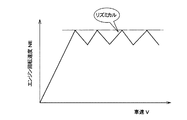
これによって、例えば、車両の低中速走行および低中出力走行では、変速機構10が無段変速状態とされて車両の燃費性能が確保されるが、実際の車速Vが前記判定車速V1を越えるような高速走行では変速機構10が有段の変速機として作動する有段変速状態とされ専ら機械的な動力伝達経路でエンジン8の出力が駆動輪38へ伝達されて電気的な無段変速機として作動させる場合に発生する動力と電気エネルギとの間の変換損失が抑制されて燃費が向上させられる。また、出力トルクTOUTなどの前記駆動力関連値が判定トルクT1を越えるような高出力走行では変速機構10が有段の変速機として作動する有段変速状態とされ専ら機械的な動力伝達経路でエンジン8の出力が駆動輪38へ伝達されて電気的な無段変速機として作動させる領域が車両の低中速走行および低中出力走行となって、第1電動機M1が発生すべき電気的エネルギ換言すれば第1電動機M1が伝える電気的エネルギの最大値を小さくできて第1電動機M1或いはそれを含む車両の駆動装置が一層小型化される。また、他の考え方として、この高出力走行においては燃費に対する要求より運転者の駆動力に対する要求が重視されるので、無段変速状態より有段変速状態(定変速状態)に切り換えられるのである。これによって、ユーザは、例えば図8に示すような有段自動変速走行におけるアップシフトに伴うエンジン回転速度Nの変化すなわち変速に伴うリズミカルなエンジン回転速度Nの変化が楽しめる。 As a result, for example, in low-medium speed traveling and low-medium power traveling of the vehicle, the speed change mechanism 10 is set to a continuously variable transmission state to ensure fuel efficiency of the vehicle, but the actual vehicle speed V exceeds the determination vehicle speed V1. In such high speed running, the transmission mechanism 10 is in a stepped transmission state in which it operates as a stepped transmission, and the output of the engine 8 is transmitted to the drive wheels 38 exclusively through a mechanical power transmission path, so that the electric continuously variable transmission. As a result, the conversion loss between the power and the electric energy generated when the power is operated is suppressed, and the fuel efficiency is improved. Further, in high-power running such that the driving force-related value such as the output torque T OUT exceeds the determination torque T1, the transmission mechanism 10 is in a stepped transmission state in which it operates as a stepped transmission, and is exclusively a mechanical power transmission path. Thus, the region in which the output of the engine 8 is transmitted to the drive wheels 38 to operate as an electric continuously variable transmission is the low / medium speed travel and the low / medium power travel of the vehicle. In other words, the maximum value of the electric energy transmitted by the first electric motor M1 can be reduced, and the first electric motor M1 or a vehicle drive device including the first electric motor M1 can be further downsized. As another concept, in this high-power running, the demand for the driver's driving force is more important than the demand for fuel consumption, so that the stepless speed change state is switched to the stepped speed change state (constant speed change state). Thus, the user, for example, changes i.e. changes in the rhythmic engine rotational speed N E due to the shift of the engine speed N E with the stepped up-shift of the automatic shifting control, as shown in FIG. 8 can enjoy.

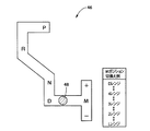
図9は図5に示した複数種類のシフトポジションを手動操作により切り換える切換装置46の一例を示す図である。切換装置46は、例えば運転席の横に配設され、複数種類のシフトポジションを選択するために操作されるシフトレバー48を備えている。そのシフトレバー48は、例えば図2の係合作動表に示されるように第1クラッチC1および第2クラッチC2のいずれの係合装置も係合されないような変速機構10内つまり自動変速部20内の動力伝達経路が遮断されたニュートラル状態すなわち中立状態とし且つ自動変速部20の出力軸22をロックするための駐車ポジション「P(パーキング)」、後進走行のための後進走行ポジション「R(リバース)」、変速機構10内の動力伝達経路が遮断された中立状態とする中立ポジション「N(ニュートラル)」、前進自動変速走行ポジション「D(ドライブ)」、または前進手動変速走行ポジション「M(マニュアル)」へ手動操作されるように設けられている。   FIG. 9 is a diagram showing an example of the switching device 46 for switching a plurality of types of shift positions shown in FIG. 5 by manual operation. The switching device 46 includes, for example, a shift lever 48 that is disposed beside the driver's seat and is operated to select a plurality of types of shift positions. For example, as shown in the engagement operation table of FIG. 2, the shift lever 48 is provided in the transmission mechanism 10, that is, in the automatic transmission unit 20 so that neither of the engagement devices of the first clutch C <b> 1 and the second clutch C <b> 2 is engaged. A neutral position where the power transmission path of the vehicle is cut off, that is, a neutral state and a parking position “P (parking)” for locking the output shaft 22 of the automatic transmission unit 20, a reverse traveling position “R (reverse) for reverse traveling ”, Neutral position“ N (neutral) ”in which the power transmission path in transmission mechanism 10 is interrupted, neutral forward position“ N (neutral) ”, forward automatic shift travel position“ D (drive) ”, or forward manual shift travel position“ M (manual) ” ”To be manually operated.

例えば、上記シフトレバー48の各シフトポジションへの手動操作に連動してそのシフトレバー48に機械的に連結された油圧制御回路42内のマニュアル弁が切り換えられて、図2の係合作動表に示す後進ギヤ段「R」、ニュートラル「N」、前進ギヤ段「D」等が成立するように油圧制御回路42が機械的に切り換えられる。また、「D」または「M」ポジションにおける図2の係合作動表に示す1st乃至5thの各変速段は、油圧制御回路42内の電磁弁が電気的に切り換えられることにより成立させられる。   For example, the manual valve in the hydraulic control circuit 42 mechanically connected to the shift lever 48 is switched in conjunction with the manual operation of the shift lever 48 to each shift position, and the engagement operation table of FIG. The hydraulic control circuit 42 is mechanically switched so that the reverse gear stage “R”, the neutral “N”, the forward gear stage “D”, and the like are established. Further, the first to fifth shift stages shown in the engagement operation table of FIG. 2 at the “D” or “M” position are established by electrically switching the electromagnetic valve in the hydraulic control circuit 42.

上記「P」乃至「M」ポジションに示す各シフトポジションは、「P」ポジションおよび「N」ポジションの各非走行ポジションは例えば図2の係合作動表に示されるように第1クラッチC1および第2クラッチC2のいずれもが解放されるような自動変速部20内の動力伝達経路が遮断された車両を駆動不能とする第1クラッチC1および第2クラッチC2による動力伝達経路の動力伝達遮断状態へ切換えを選択するための非駆動ポジションである。また、「R」ポジション、「D」ポジションおよび「M」ポジションの各走行ポジションは例えば図2の係合作動表に示されるように第1クラッチC1および第2クラッチC2の少なくとも一方が係合されるような自動変速部20内の動力伝達経路が連結された車両を駆動可能とする第1クラッチC1および/または第2クラッチC2による動力伝達経路の動力伝達可能状態へ切換えを選択するための駆動ポジションでもある。   The shift positions indicated by the “P” to “M” positions are the non-travel positions of the “P” position and the “N” position, for example, as shown in the engagement operation table of FIG. The power transmission path of the first clutch C1 and the second clutch C2, which disables driving of the vehicle in which the power transmission path in the automatic transmission unit 20 is disengaged so that both of the two clutches C2 are released, is switched to the power transmission cutoff state. This is a non-driving position for selecting switching. Further, at each of the traveling positions of the “R” position, the “D” position, and the “M” position, for example, as shown in the engagement operation table of FIG. 2, at least one of the first clutch C1 and the second clutch C2 is engaged. Driving for selecting switching of the power transmission path to the power transmission enabled state by the first clutch C1 and / or the second clutch C2 that enables driving of the vehicle to which the power transmission path in the automatic transmission unit 20 is connected. It is also a position.

具体的には、シフトレバー48が「P」ポジション或いは「N」ポジションから「R」ポジションへ手動操作されることで、第2クラッチC2が係合されて自動変速部20内の動力伝達経路が動力伝達遮断状態から動力伝達可能状態とされ、シフトレバー48が「N」ポジションから「D」ポジションへ手動操作されることで、少なくとも第1クラッチC1が係合されて自動変速部20内の動力伝達経路が動力伝達遮断状態から動力伝達可能状態とされる。また、「D」ポジションは最高速走行ポジションでもあり、「M」ポジションにおける例えば「4」レンジ乃至「L」レンジはエンジンブレーキ効果が得られるエンジンブレーキレンジでもある。   Specifically, when the shift lever 48 is manually operated from the “P” position or the “N” position to the “R” position, the second clutch C2 is engaged and the power transmission path in the automatic transmission unit 20 is changed. When the power transmission is cut off from the power transmission cut-off state and the shift lever 48 is manually operated from the “N” position to the “D” position, at least the first clutch C1 is engaged and the power in the automatic transmission unit 20 is increased. The transmission path is changed from a power transmission cutoff state to a power transmission enabled state. Further, the “D” position is also the fastest running position, and the “M” position, for example, the “4” range to the “L” range is also an engine brake range in which an engine brake effect can be obtained.

上記「M」ポジションは、例えば車両の前後方向において上記「D」ポジションと同じ位置において車両の幅方向に隣接して設けられており、シフトレバー48が「M」ポジションへ操作されることにより、「D」レンジ乃至「L」レンジの何れかがシフトレバー48の操作に応じて選択される。具体的には、この「M」ポジションには、車両の前後方向にアップシフト位置「+」、およびダウンシフト位置「−」が設けられており、シフトレバー48がそれ等のアップシフト位置「+」またはダウンシフト位置「−」へ操作されると、「D」レンジ乃至「L」レンジの何れかが選択される。例えば、「M」ポジションにおいて選択される「D」レンジ乃至「L」レンジの5つの変速レンジは、変速機構10の自動変速制御が可能なトータル変速比γTの変化範囲における高速側(変速比が最小側)のトータル変速比γTが異なる複数種類の変速レンジであり、また自動変速部20の変速が可能な最高速側変速段が異なるように変速段(ギヤ段)の変速範囲を制限するものである。また、シフトレバー48はスプリング等の付勢手段により上記アップシフト位置「+」およびダウンシフト位置「−」から、「M」ポジションへ自動的に戻されるようになっている。また、切換装置46にはシフトレバー48の各シフトポジションを検出するためのシフトポジションセンサ49が備えられており、そのシフトレバー48のシフトポジションPSHを表す信号や「M」ポジションにおける操作回数等を電子制御装置40へ出力する。 The “M” position is provided adjacent to the width direction of the vehicle at the same position as the “D” position, for example, in the longitudinal direction of the vehicle, and when the shift lever 48 is operated to the “M” position, Any of the “D” range to the “L” range is selected in accordance with the operation of the shift lever 48. Specifically, the “M” position is provided with an upshift position “+” and a downshift position “−” in the front-rear direction of the vehicle, and the shift lever 48 is provided with the upshift position “+”. ”Or the downshift position“ − ”, one of the“ D ”range to the“ L ”range is selected. For example, the five shift ranges from the “D” range to the “L” range selected at the “M” position are the high speed side (the shift ratio is less than the total shift ratio γT in which the automatic shift control of the transmission mechanism 10 is possible). The minimum speed range is a plurality of speed ranges with different total gear ratios γT, and the speed range of the gear speed (gear speed) is limited so that the maximum speed gear speed at which the automatic transmission 20 can change the speed is different It is. The shift lever 48 is automatically returned from the upshift position “+” and the downshift position “−” to the “M” position by a biasing means such as a spring. Further, the switching device 46 is provided with a shift position sensor 49 for detecting each shift position of the shift lever 48, a signal indicating the shift position P SH of the shift lever 48, the number of operations at the “M” position, and the like. Is output to the electronic control unit 40.

例えば、「D」ポジションがシフトレバー48の操作により選択された場合には、図6に示す予め記憶された変速マップや切換マップに基づいて切換制御手段50により変速機構10の変速状態の自動切換制御が実行され、ハイブリッド制御手段52により差動部11の無段変速制御が実行され、有段変速制御手段54により自動変速部20の自動変速制御が実行される。例えば、変速機構10が有段変速状態に切り換えられる有段変速走行時には変速機構10が例えば図2に示すような第1速ギヤ段乃至第5速ギヤ段の範囲で自動変速制御され、或いは変速機構10が無段変速状態に切り換えられる無段変速走行時には変速機構10が差動部11の無段的な変速比幅と自動変速部20の第1速ギヤ段乃至第4速ギヤ段の範囲で自動変速制御される各ギヤ段とで得られる変速機構10の変速可能なトータル変速比γTの変化範囲内で自動変速制御される。この「D」ポジションは変速機構10の自動変速制御が実行される制御様式である自動変速走行モード(自動モード)を選択するシフトポジションでもある。   For example, when the “D” position is selected by operating the shift lever 48, the shift control means 50 automatically switches the shift state of the transmission mechanism 10 based on the shift map and the switch map stored in advance as shown in FIG. The control is executed, the continuously variable transmission control of the differential unit 11 is executed by the hybrid control unit 52, and the automatic transmission control of the automatic transmission unit 20 is executed by the stepped transmission control unit 54. For example, when the speed change mechanism 10 is switched to the stepped speed change state, the speed change mechanism 10 is automatically controlled in the range of the first to fifth speed gears as shown in FIG. During continuously variable speed travel where the mechanism 10 is switched to the continuously variable speed state, the speed change mechanism 10 has a continuously variable gear ratio range of the differential unit 11 and a range from the first speed gear stage to the fourth speed gear stage of the automatic transmission unit 20. Thus, the automatic transmission control is performed within the change range of the total speed ratio γT that can be changed by the transmission mechanism 10 obtained by the respective gear stages that are automatically controlled by the transmission. This “D” position is also a shift position for selecting an automatic shift traveling mode (automatic mode) which is a control mode in which automatic shift control of the transmission mechanism 10 is executed.

或いは、「M」ポジションがシフトレバー48の操作により選択された場合には、変速レンジの最高速側変速段或いは変速比を越えないように、切換制御手段50、ハイブリッド制御手段52、および有段変速制御手段54により変速機構10の各変速レンジで変速可能なトータル変速比γTの範囲で自動変速制御される。例えば、変速機構10が有段変速状態に切り換えられる有段変速走行時には変速機構10が各変速レンジで変速機構10が変速可能なトータル変速比γTの範囲で自動変速制御され、或いは変速機構10が無段変速状態に切り換えられる無段変速走行時には変速機構10が差動部11の無段的な変速比幅と各変速レンジに応じた自動変速部20の変速可能な変速段の範囲で自動変速制御される各ギヤ段とで得られる変速機構10の各変速レンジで変速可能なトータル変速比γTの範囲で自動変速制御される。この「M」ポジションは変速機構10の手動変速制御が実行される制御様式である手動変速走行モード(手動モード)を選択するシフトポジションでもある。   Alternatively, when the “M” position is selected by operating the shift lever 48, the switching control means 50, the hybrid control means 52, and the stepped gear are set so as not to exceed the highest speed side shift speed or gear ratio of the shift range. The shift control means 54 performs automatic shift control within the range of the total gear ratio γT that can be shifted in each shift range of the transmission mechanism 10. For example, when the transmission mechanism 10 is switched to the stepped transmission state, the transmission mechanism 10 is automatically controlled to shift within the range of the total transmission ratio γT at which the transmission mechanism 10 can shift in each shift range, or the transmission mechanism 10 During continuously variable speed driving that is switched to a continuously variable speed state, the speed change mechanism 10 automatically shifts within the range of the continuously variable speed ratio range of the differential unit 11 and the shift speed range of the automatic transmission unit 20 according to each shift range. Automatic shift control is performed within the range of the total gear ratio γT that can be shifted in each shift range of the transmission mechanism 10 obtained by each gear stage to be controlled. This “M” position is also a shift position for selecting a manual shift traveling mode (manual mode) which is a control mode in which manual shift control of the transmission mechanism 10 is executed.

図5に戻り、シフトポジション判定手段80は、シフトポジションセンサ49からのシフトレバー48のシフトポジションPSHを表す信号に基づいて現在シフトレバー48がいずれのポジションとなっているか、或いはシフトレバー48がいずれのポジションへ操作されたかを判定する。例えば、シフトポジション判定手段80は、上記シフトポジションPSHを表す信号に基づいてシフトレバー48のシフトポジションが「N」ポジション或いは「P」ポジションであるか否かを判定する。また、例えば、シフトポジション判定手段80は、上記シフトポジションPSHを表す信号に基づいてシフトレバー48のシフトポジションが「N」ポジション或いは「P」ポジションから「R」ポジション或いは「D」ポジションへ操作されたか否かを判定する。 Returning to FIG. 5, the shift position determination means 80 determines which position the shift lever 48 is currently in based on the signal representing the shift position P SH of the shift lever 48 from the shift position sensor 49, or whether the shift lever 48 is It is determined to which position it was operated. For example, the shift position determining means 80 determines whether the shift position of the shift lever 48 based on a signal representing the shift position P SH is the "N" position or the "P" position. Further, for example, the shift position determination means 80 operates the shift position of the shift lever 48 from the “N” position or “P” position to the “R” position or “D” position based on the signal indicating the shift position P SH. It is determined whether or not it has been done.

ところで、シフトレバー48のシフトポジションが「N」ポジション或いは「P」ポジションから「R」ポジション或いは「D」ポジションへ操作されたことすなわち非駆動ポジションから駆動ポジションへ手動操作(マニュアルシフト)されたことに伴い第1クラッチC1および第2クラッチC2の少なくとも一方の係合装置が係合されると、エンジン作動時であればそのエンジントルクTが自動変速部20を介して駆動輪38へ伝達される。この時、シフトレバー48が非駆動ポジションから駆動ポジションへ手動操作された際に、駆動輪38へ伝達されるエンジントルクTが大きい程すなわち第1クラッチC1および/または第2クラッチC2が伝達すべきエンジントルクTが大きい程第1クラッチC1および/または第2クラッチC2の耐久性が低下する可能性があった。 By the way, the shift position of the shift lever 48 has been operated from the “N” position or “P” position to the “R” position or “D” position, that is, manually operated (manual shift) from the non-drive position to the drive position. Accordingly, when at least one of the engagement devices of the first clutch C1 and the second clutch C2 is engaged, the engine torque TE is transmitted to the drive wheel 38 via the automatic transmission unit 20 when the engine is operating. The At this time, when the shift lever 48 is manually operated from the non-driving position to the driving position, the larger the engine torque T E that is transmitted to the drive wheels 38 that is the first clutch C1 and / or the second clutch C2 to transfer the larger the engine torque T E durability of the first clutch C1 and / or the second clutch C2 is may decrease to.

そこで、シフトレバー48の非駆動ポジションから駆動ポジションへの手動操作に伴う第1クラッチC1および/または第2クラッチC2の耐久性低下を抑制する制御作動について以下に説明する。尚、非駆動ポジションへ切り換えられている際のエンジン作動としては、エンジン水温が定常走行時に比較して低いためにエンジンを作動させて暖気する必要がある場合、蓄電装置60の充電容量SOCが低下して第1電動機M1による発電が必要となった場合、エアコン等の補機のための駆動電流の不足やそれら補機をエンジン8により駆動する必要が生じた場合、或いは車両がエンジン8を駆動力源として走行するエンジン走行中であった場合等が想定される。   Therefore, a control operation for suppressing a decrease in durability of the first clutch C1 and / or the second clutch C2 due to a manual operation of the shift lever 48 from the non-drive position to the drive position will be described below. Note that the engine operation at the time of switching to the non-driving position is that the engine water temperature is lower than that during steady running, so that it is necessary to warm up the engine by operating the engine. When power generation by the first electric motor M1 becomes necessary, when there is a shortage of driving current for auxiliary equipment such as an air conditioner or when it is necessary to drive these auxiliary equipment by the engine 8, or the vehicle drives the engine 8 It is assumed that the engine is traveling as a power source.

アクセル踏込判定手段82は、前記シフトポジション判定手段80によりシフトレバー48のシフトポジションが「N」ポジション或いは「P」ポジションであると判定される場合に、アクセルペダル45が踏込操作されているか否かを、例えば実際のアクセルペダル操作量Accが所定アクセルペダル操作量Acc’を超えているか否かにより判定する。上記所定アクセルペダル操作量Acc’は、シフトレバー48の「N」ポジション或いは「P」ポジションにおいてユーザによりアクセルペダル45が踏込操作されていると判定されるアクセルペダル操作量として予め定められて記憶されている値である。   The accelerator depression determination means 82 determines whether or not the accelerator pedal 45 is depressed when the shift position determination means 80 determines that the shift position of the shift lever 48 is the “N” position or the “P” position. Is determined, for example, based on whether the actual accelerator pedal operation amount Acc exceeds a predetermined accelerator pedal operation amount Acc ′. The predetermined accelerator pedal operation amount Acc ′ is determined and stored in advance as an accelerator pedal operation amount that is determined by the user to depress the accelerator pedal 45 at the “N” position or the “P” position of the shift lever 48. It is a value.

エンジン回転制御手段84は、シフトレバー48が非駆動ポジションへ切り換えられているときすなわち前記シフトポジション判定手段80によりシフトレバー48のシフトポジションが「N」ポジション或いは「P」ポジションであると判定されるときであって、アクセル踏込判定手段82によりアクセルペダル45が踏込操作されていると判定されるときには、シフトレバー48が非駆動ポジションから駆動ポジションへ手動操作された際の第1クラッチC1および/または第2クラッチC2の耐久性低下を抑制するために、アクセルペダル45の踏込操作に拘わらずエンジン回転速度Nが所定エンジン回転速度N’以上とならないように回転制御する。 The engine rotation control means 84 determines that the shift position of the shift lever 48 is the “N” position or the “P” position when the shift lever 48 is switched to the non-driving position, that is, the shift position determination means 80. When it is determined by the accelerator depression determination means 82 that the accelerator pedal 45 is depressed, the first clutch C1 and / or the shift lever 48 is manually operated from the non-driving position to the driving position. in order to suppress the deterioration in durability of the second clutch C2, the engine rotational speed N E regardless depressing operation of the accelerator pedal 45 rotates controlled so as not to be a predetermined engine speed N E 'or.

例えば、上記エンジン回転制御手段84は、アクセルペダル45の踏込操作に拘わらずエンジン出力を制御することによりエンジン回転速度Nが所定エンジン回転速度N’以上とならないように回転制御する。具体的には、エンジン回転制御手段84は、電子スロットル弁96の開度を絞ったり、燃料噴射装置98による燃料供給量を減少させたり、点火装置99によるエンジン8の点火時期を遅角させる指令を単独で或いは組み合わせてエンジン出力制御装置43に出力してエンジン回転速度Nが所定エンジン回転速度N’以上とならないように回転制御する。 For example, the engine control unit 84 controls the rotation so that the engine rotational speed N E is not a predetermined engine rotational speed N E 'or by controlling the engine output irrespective of the depression operation of the accelerator pedal 45. Specifically, the engine rotation control means 84 commands to reduce the opening of the electronic throttle valve 96, reduce the amount of fuel supplied by the fuel injection device 98, or retard the ignition timing of the engine 8 by the ignition device 99. alone or in combination engine output control device 43 outputs to the engine rotational speed N E is rotated controlled so as not to be a predetermined engine speed N E 'or.

上記所定エンジン回転速度N’は、シフトレバー48が非駆動ポジションから駆動ポジションへ手動操作に伴う第1クラッチC1および/または第2クラッチC2の耐久性低下を抑制するように、シフトレバー48の「N」ポジション或いは「P」ポジションにおけるアクセルペダル45の踏込操作によるエンジン回転速度Nの吹き上がり(所謂エンジン8のレーシング)を制限する為のエンジン回転速度として予め実験的に求められて記憶されている値であって例えば2000rpm程度に設定されている。 The predetermined engine rotational speed N E ′ is such that the shift lever 48 is controlled so as to suppress a decrease in durability of the first clutch C1 and / or the second clutch C2 due to manual operation from the non-drive position to the drive position. in advance experimentally sought stored as an engine rotational speed for limiting the racing (racing so-called engine 8) of the engine speed N E by depressing the accelerator pedal 45 in the "N" position or the "P" position For example, about 2000 rpm.

電動機制御手段86は、シフトレバー48が非駆動ポジションへ切り換えられているときすなわち前記シフトポジション判定手段80によりシフトレバー48のシフトポジションが「N」ポジション或いは「P」ポジションであると判定されるときであって、前記アクセル踏込判定手段82によりアクセルペダル45が踏込操作されていないと判定されるときには、或いは前記エンジン回転制御手段84によりエンジン回転速度Nが所定エンジン回転速度N’以上とならないように回転制御されるときには、ハイブリッド制御手段52にエンジン回転速度Nの回転制御を実施させない。ハイブリッド制御手段により第1電動機M1および/または第2電動機M2を用いてエンジン回転速度Nが所定エンジン回転速度N’以上とならないように回転制御する必要がないからである。例えば、電動機制御手段86は、第1電動機M1および第2電動機M2を無負荷状態としてエンジン回転速度Nの回転制御を実施しないように前記ハイブリッド制御手段52に指令を出力する。前記ハイブリッド制御手段52は、この電動機制御手段の上記指令に従って第1電動機M1および第2電動機M2への駆動電流を遮断して第1電動機M1および第2電動機M2を無負荷状態とする。 When the shift lever 48 is switched to the non-drive position, that is, when the shift position determination unit 80 determines that the shift position of the shift lever 48 is the “N” position or the “P” position. a is, the when the accelerator pedal 45 by an accelerator depression judging means 82 is determined not to be depressing the or the engine control unit 84 by the engine rotational speed N E is not a predetermined engine rotational speed N E 'or when the rotation control in this way, not carrying out the rotation control of the engine rotational speed N E to the hybrid control means 52. This is because the first electric motor M1 and / or the engine rotational speed N E using the second electric motor M2 is no need to rotate control so as not to be a predetermined engine speed N E 'or by the hybrid control means. For example, motor control unit 86 outputs a command to the hybrid control means 52 as the rotation control is not performed in the engine rotational speed N E of the first and second electric motors M1 and M2 as a no-load state. The hybrid control means 52 cuts off the drive current to the first motor M1 and the second motor M2 in accordance with the command from the motor control means, thereby putting the first motor M1 and the second motor M2 into a no-load state.

このように、第1電動機M1および第2電動機M2が無負荷状態とされるとそれら電動機を制御する為の電気的エネルギー損失が抑制されたり或いはエンジン8に対する負荷が低減されて燃費が向上する。また、第1電動機M1および第2電動機M2が無負荷状態とされて差動部11が電気的に中立状態(ニュートラル)とされると、シフトレバー48が非駆動ポジションから駆動ポジションへ切り換えられたときにはエンジントルクTが伝達されない状態すなわち差動部11から出力されるトルクが略零とされる状態で第1クラッチC1および/または第2クラッチC2が係合されるので、第1クラッチC1および/または第2クラッチC2の耐久性が一層向上する。 As described above, when the first electric motor M1 and the second electric motor M2 are brought into the no-load state, the electric energy loss for controlling the electric motors is suppressed or the load on the engine 8 is reduced to improve the fuel efficiency. Further, when the first electric motor M1 and the second electric motor M2 are in a no-load state and the differential unit 11 is in an electrically neutral state (neutral), the shift lever 48 is switched from the non-driving position to the driving position. sometimes because the first clutch C1 and / or the second clutch C2 in the state in which torque is substantially zero engine torque T E is output from the state, that the differential portion 11 is not transmitted is engaged, the first clutch C1 and / Or durability of the second clutch C2 is further improved.

伝達部材回転制御手段88は、シフトレバー48が非駆動ポジションから駆動ポジションへ切り換えられたときすなわち前記シフトポジション判定手段80によりシフトレバー48のシフトポジションが「N」ポジション或いは「P」ポジションから「R」ポジション或いは「D」ポジションへ操作されたと判定されたときには、第1クラッチC1および/または第2クラッチC2の係合に際して第1クラッチC1および第2クラッチC2の相対回転速度が抑制された状態で係合されるように、第1電動機M1および/または第2電動機M2を用いて伝達部材18の回転速度を回転制御する。   When the shift lever 48 is switched from the non-drive position to the drive position, that is, the shift position determination means 80 changes the shift position of the shift lever 48 from the “N” position or “P” position to “R”. When the first or second clutch C1 and / or the second clutch C2 is engaged, the relative rotational speeds of the first and second clutches C1 and C2 are suppressed. The rotation speed of the transmission member 18 is controlled to rotate using the first electric motor M1 and / or the second electric motor M2.

具体的には、上記伝達部材回転制御手段88は、第1クラッチC1および第2クラッチC2の相対回転速度が抑制された状態で係合されるように、車速Vとギヤ比とから一意的に決められる第1クラッチC1および/または第2クラッチC2の係合状態での自動変速部20の入力回転速度NIN(=出力軸回転速度NOUT×ギヤ比γ)すなわち伝達部材18の目標回転速度N18’を算出する。例えば、車両停止状態となる車速Vが零の場合には伝達部材18の目標回転速度N18’は零とされ、車両の前進走行中にシフトレバー48が「N」ポジションへ操作された場合には伝達部材18の目標回転速度は車速Vと前進走行用変速段のギヤ比例えば第1速ギヤ比とから算出される。 Specifically, the transmission member rotation control means 88 is uniquely determined from the vehicle speed V and the gear ratio so as to be engaged with the relative rotational speeds of the first clutch C1 and the second clutch C2 being suppressed. The input rotational speed N IN (= output shaft rotational speed N OUT × gear ratio γ) of the automatic transmission 20 with the determined first clutch C1 and / or second clutch C2 engaged, that is, the target rotational speed of the transmission member 18 N 18 ′ is calculated. For example, when the vehicle speed V at which the vehicle is stopped is zero, the target rotational speed N 18 ′ of the transmission member 18 is zero, and the shift lever 48 is operated to the “N” position while the vehicle is traveling forward. The target rotational speed of the transmission member 18 is calculated from the vehicle speed V and the gear ratio of the forward travel gear, for example, the first gear ratio.

そして、上記伝達部材回転制御手段88は、差動部11の電気的な無段変速により第1電動機M1および/または第2電動機M2を用いて第2電動機回転速度NM2を、上記伝達部材18の目標回転速度N18’に向かって同期制御するようにハイブリッド制御手段52に指令を出力する。これにより、シフトレバー48が非駆動ポジションから駆動ポジションへ切り換えられたときには第1クラッチC1および第2クラッチC2の相対回転速度が抑制された状態で第1クラッチC1および/または第2クラッチC2が係合されるので、第1クラッチC1および/または第2クラッチC2の耐久性が一層向上する。或いはまた、それに加えてその切換えに伴うシフトショックが一層抑制される。また、第1クラッチC1および第2クラッチC2の相対回転速度が抑制された状態での係合作動期間では、有段変速制御手段54は油圧制御回路42に第1クラッチC1および/または第2クラッチC2の油圧を漸増させるのではなくファーストアプライさせても、耐久性の低下が抑制される。或いはまた、それに加えてシフトショックが抑制される。 Then, the transmitting member rotation control means 88, the second electric motor rotation speed N M2 to the electrically controlled continuously variable transmission using the first electric motor M1 and / or the second electric motor M2 of the differential portion 11, the transmission member 18 A command is output to the hybrid control means 52 so as to perform the synchronous control toward the target rotational speed N 18 ′. Thus, when the shift lever 48 is switched from the non-drive position to the drive position, the first clutch C1 and / or the second clutch C2 are engaged with the relative rotational speeds of the first clutch C1 and the second clutch C2 being suppressed. As a result, the durability of the first clutch C1 and / or the second clutch C2 is further improved. Alternatively, in addition to that, the shift shock accompanying the switching is further suppressed. Further, in the engagement operation period in a state where the relative rotational speeds of the first clutch C1 and the second clutch C2 are suppressed, the stepped speed change control means 54 sends the first clutch C1 and / or the second clutch to the hydraulic control circuit 42. Even if the hydraulic pressure of C2 is first increased instead of gradually increasing, the decrease in durability is suppressed. Alternatively, shift shock is suppressed in addition thereto.

ここで、差動部11は無段変速状態と有段変速状態(定変速状態)とに選択的に切換え可能であって、差動部11の有段変速状態においては、第1電動機回転速度NM1、第2電動機回転速度NM2、およびエンジン回転速度Nが互いに拘束されて自由度が確保されない。例えば、差動部11の有段変速状態においては、電動機制御手段86により第1電動機M1および第2電動機M2が無負荷状態とされてもエンジントルクTが伝達部材18に伝達される状態とされて差動部11が電気的に中立状態とされない。 Here, the differential unit 11 can be selectively switched between a continuously variable transmission state and a stepped transmission state (constant transmission state), and in the stepped transmission state of the differential unit 11, the first motor rotation speed. N M1 , second motor rotation speed N M2 , and engine rotation speed NE are mutually restrained, and the degree of freedom is not ensured. For example, in the stepped speed change state of the differential unit 11, the engine torque TE is transmitted to the transmission member 18 even when the first motor M <b> 1 and the second motor M <b> 2 are unloaded by the motor control unit 86. Thus, the differential unit 11 is not electrically neutralized.

そこで、前記切換制御手段50は、前述の機能に加えて、シフトレバー48が非駆動ポジションへ切り換えられているときすなわち前記シフトポジション判定手段80によりシフトレバー48のシフトポジションが「N」ポジション或いは「P」ポジションであると判定されるときには、例えば電動機制御手段86により差動部11が電気的に中立状態とされたり、或いは伝達部材回転制御手段88により第1電動機M1および/または第2電動機M2を用いて第2電動機回転速度NM2が回転制御されるように、切換クラッチC0および切換ブレーキB0を解放させる指令を油圧制御回路42へ出力して差動部11を無段変速状態すなわち動力分配機構16を差動状態とする。 Therefore, in addition to the above-described function, the switching control means 50 is configured such that when the shift lever 48 is switched to the non-driving position, that is, the shift position of the shift lever 48 is set to the “N” position or “ When it is determined that the position is the “P” position, for example, the differential control unit 11 is electrically neutralized by the motor control unit 86 or the first motor M1 and / or the second motor M2 is transmitted by the transmission member rotation control unit 88. Is used to output the command for releasing the switching clutch C0 and the switching brake B0 to the hydraulic control circuit 42 so that the rotation speed of the second motor rotation speed NM2 is controlled. The mechanism 16 is set to a differential state.

図10は、電子制御装置40の制御作動の要部すなわちシフトレバー48が非駆動ポジションにあるときにエンジン8が作動している場合においてシフトレバー48が非駆動ポジションから駆動ポジションへ操作された際の第1クラッチC1および/または第2クラッチC2の耐久性の低下を抑制するための差動部11の制御作動を説明するフローチャートであり、例えば数msec乃至数十msec程度の極めて短いサイクルタイムで繰り返し実行される。また、図11は、図10のフローチャートに示す制御作動を説明するタイムチャートであり、シフトレバー48が「N」ポジションから「D」ポジションへ操作される際すなわちN→Dシフトの際の制御作動を示している。   FIG. 10 shows the main part of the control operation of the electronic control unit 40, that is, when the shift lever 48 is operated from the non-drive position to the drive position when the engine 8 is operating when the shift lever 48 is in the non-drive position. 6 is a flowchart for explaining a control operation of the differential section 11 for suppressing a decrease in the durability of the first clutch C1 and / or the second clutch C2, for example, with an extremely short cycle time of about several milliseconds to several tens of milliseconds. Repeatedly executed. FIG. 11 is a time chart for explaining the control operation shown in the flowchart of FIG. 10. The control operation when the shift lever 48 is operated from the “N” position to the “D” position, that is, when the N → D shift is performed. Is shown.

先ず、前記シフトポジション判定手段80に対応するステップ(以下、ステップを省略する)S1において、シフトポジションセンサ49からのシフトレバー48のシフトポジションPSHを表す信号に基づいてシフトレバー48のシフトポジションが非駆動ポジションである「N」ポジション或いは「P」ポジションであるか否かが判定される。このS1の判断が否定される場合はS8において、現在実行されている制御装置40の各種制御手段による制御作動が実行されるか或いはそのまま本ルーチンが終了させられる。図11のt時点以前は、シフトレバー48のシフトポジションが「N」ポジションとされてこのS1の判断が肯定される場合を示している。 First, in step (hereinafter, step is omitted) S1 corresponding to the shift position determining means 80, the shift position of the shift lever 48 is determined based on a signal indicating the shift position P SH of the shift lever 48 from the shift position sensor 49. It is determined whether the “N” position or the “P” position is a non-driving position. If the determination in S1 is negative, in S8, the control operation by the various control means of the control device 40 currently being executed is executed, or this routine is ended as it is. T 2 time earlier 11, the shift position of the shift lever 48 is a "N" position determination in S1 is shown a case where the result is affirmative.

上記S1の判断が肯定される場合は前記アクセル踏込判定手段82に対応するS2において、アクセルペダル45が踏込操作されているか否かが、例えば実際のアクセルペダル操作量Accが所定アクセルペダル操作量Acc’を超えているか否かにより判定される。尚、上記S1の判断が肯定されてこのS2が実行される前には図示はしていないが前記切換制御手段50に対応するステップにおいて、切換クラッチC0および切換ブレーキB0を解放させる指令が油圧制御回路42へ出力されて動力分配機構16が差動状態とされる。   If the determination in S1 is affirmative, in S2 corresponding to the accelerator depression determination means 82, whether or not the accelerator pedal 45 is depressed is determined, for example, the actual accelerator pedal operation amount Acc is equal to the predetermined accelerator pedal operation amount Acc. Judged by whether or not 'is exceeded. Although not shown before the determination of S1 is affirmed and S2 is executed, in a step corresponding to the switching control means 50, a command for releasing the switching clutch C0 and the switching brake B0 is issued by the hydraulic control. The power is distributed to the circuit 42 and the power distribution mechanism 16 is brought into a differential state.

上記S2の判断が肯定される場合は前記エンジン回転制御手段84に対応するS3において、アクセルペダル45の踏込操作によるエンジン8のレーシングを制限する為に、アクセルペダル45の踏込操作に拘わらずエンジン出力を制御することによりエンジン回転速度Nが所定エンジン回転速度N’以上例えば2000rpm程度以上とならないように回転制御される。図11のt時点乃至t時点のエンジン回転速度Nは、このS3が実行されて所定エンジン回転速度N’以上とならないように制限されていることを示している。 If the determination in S2 is affirmative, in S3 corresponding to the engine rotation control means 84, the engine output is controlled regardless of the depression operation of the accelerator pedal 45 in order to limit the racing of the engine 8 by the depression operation of the accelerator pedal 45. engine rotational speed N E is controlled to rotate so as not to be a predetermined engine speed N E 'or example 2000rpm about more by controlling. Time point t 1 to t 2 when the engine rotational speed N E of FIG. 11 shows that it is limited so as not to be a predetermined engine speed N E 'over the S3 is being executed.

前記S2の判断が否定される場合、或いは上記S3に続いて前記電動機制御手段86に対応するS4において、前記ハイブリッド制御手段52に第1電動機M1および/または第2電動機M2を用いたエンジン回転速度Nの回転制御すなわちエンジン回転速度Nを所定エンジン回転速度N’以上とならないようにする回転制御を実施させない。図11のt時点乃至t時点の第1電動機回転速度NM1および第2電動機回転速度NM2は、このS4にて差動部11が中立状態とされて回転制御されていない状態すなわち空転状態(図11では成行き状態)を示している。続いて、前記シフトポジション判定手段80に対応するS5において、シフトポジションセンサ49からのシフトレバー48のシフトポジションPSHを表す信号に基づいてシフトレバー48のシフトポジションが「N」ポジション或いは「P」ポジションから「R」ポジション或いは「D」ポジションへ操作されたか否かが判定される。このS5の判断が否定される場合は前記S2に戻り、このS5の判断が肯定されるまでS2乃至S4が切り返し実行される。図11のt時点は、シフトレバー48が「N」ポジションから「D」ポジションへ操作されてこのS5の判断が肯定される場合を示している。 If the determination in S2 is negative, or in S4 corresponding to the electric motor control means 86 following S3, the engine speed using the first electric motor M1 and / or the second electric motor M2 as the hybrid control means 52 N not the rotation control or the engine rotational speed N E of the E by implementing the rotation control to avoid the predetermined engine rotational speed N E 'or. The first motor rotation speed N M1 and the second motor rotation speed N M2 from the time point t 1 to the time point t 2 in FIG. 11 are the states in which the differential unit 11 is in the neutral state and the rotation control is not performed in this S4, The state (the state of success in FIG. 11) is shown. Subsequently, in S5 corresponding to the shift position determination means 80, the shift position of the shift lever 48 is determined to be “N” position or “P” based on the signal representing the shift position P SH of the shift lever 48 from the shift position sensor 49. It is determined whether or not an operation has been performed from the position to the “R” position or the “D” position. If the determination in S5 is negative, the process returns to S2, and S2 to S4 are repeatedly executed until the determination in S5 is affirmed. T 2 time points 11, the shift lever 48 is operated from the "N" position to the "D" position determination in S5 is shows the case the result is affirmative.

上記S5の判断が肯定される場合は前記伝達部材回転制御手段88に対応するS6において、車速Vとギヤ比とから一意的に決められる第1クラッチC1および/または第2クラッチC2の係合状態での伝達部材18の目標回転速度N18’(=出力軸回転速度NOUT×ギヤ比γ)が算出される。そして、第1電動機M1および/または第2電動機M2を用いて第2電動機回転速度NM2が上記伝達部材18の目標回転速度N18’に向かって同期制御するようにハイブリッド制御手段52に指令が出力される。続いて、前記有段変速制御手段54に対応するS7において、油圧制御回路42に第1クラッチC1および/または第2クラッチC2の油圧をファーストアプライさせる指令が出力される。図11のt時点乃至t時点は、第2電動機回転速度NM2の同期制御後に第1クラッチC1の油圧がファーストアプライ制御されることを示している。 If the determination in S5 is affirmative, in S6 corresponding to the transmission member rotation control means 88, the engagement state of the first clutch C1 and / or the second clutch C2 uniquely determined from the vehicle speed V and the gear ratio. The target rotational speed N 18 ′ (= output shaft rotational speed N OUT × gear ratio γ) of the transmission member 18 is calculated. Then, a command is given to the hybrid control means 52 so that the second motor rotation speed N M2 is synchronously controlled toward the target rotation speed N 18 ′ of the transmission member 18 using the first motor M1 and / or the second motor M2. Is output. Subsequently, in S7 corresponding to the stepped shift control means 54, a command for first applying the hydraulic pressure of the first clutch C1 and / or the second clutch C2 is output to the hydraulic control circuit 42. T 3 time to t 4 time points 11, hydraulic pressure of the first clutch C1 indicates that it is fast apply control after the synchronous control of the second electric motor rotation speed N M2.

上述のように、本実施例によれば、差動作用が作動可能な動力分配機構16を有する差動部11と自動変速部20とを備える変速機構10において、動力伝達経路を動力伝達可能状態と動力伝達遮断状態とに選択的に切り換える第1クラッチC1および第2クラッチC2の少なくとも一方の係合装置による動力伝達可能状態への切換えを選択するための駆動ポジション(「D」、「R」ポジション)とその係合装置による動力伝達遮断状態への切換えを選択するための非駆動ポジション(「P」、「N」ポジション)とに手動操作により切り換えるシフトレバー48が非駆動ポジションへ切り換えられているときには、エンジン回転制御手段84によりエンジン回転速度Nが所定エンジン回転速度N’以上とならないように回転制御されるので、シフトレバー48が非駆動ポジションから駆動ポジションへ切り換えられたときに、その切換えに伴って駆動輪38へ伝達されるエンジントルクTすなわちその切換えに伴って係合される第1クラッチC1および/または第2クラッチC2が伝達すべきエンジントルクTが抑制される。よって、エンジントルクTが抑制された状態で第1クラッチC1および/または第2クラッチC2が係合されてその第1クラッチC1および/または第2クラッチC2の耐久性が向上する。或いはまた、それに加えてその切換えに伴うシフトショックが抑制される。 As described above, according to the present embodiment, in the speed change mechanism 10 including the differential portion 11 having the power distribution mechanism 16 capable of operating a differential action and the automatic speed change portion 20, the power transmission path is in a state where power can be transmitted. Driving position (“D”, “R”) for selecting switching to the power transmission enabled state by the engagement device of at least one of the first clutch C1 and the second clutch C2 that selectively switches between the power transmission cutoff state and the power transmission cutoff state Position) and a shift lever 48 that is manually switched to a non-driving position ("P", "N" position) for selecting switching to a power transmission cutoff state by the engaging device is switched to the non-driving position. when you are, the engine rotational speed N E is rotated controlled so as not to be a predetermined engine speed N E 'or by the engine rotation control means 84 Runode, when the shift lever 48 is switched from the non-driving position to the driving position, the first clutch C1 engaged with the engine torque T E i.e. the switching is transmitted to the drive wheels 38 with its switching and / or the engine torque T E second clutch C2 is to be transmitted can be suppressed. Therefore, the first clutch C1 and / or the second clutch C2 are engaged in a state where the engine torque TE is suppressed, and the durability of the first clutch C1 and / or the second clutch C2 is improved. Alternatively, in addition to that, the shift shock accompanying the switching is suppressed.

また、本実施例によれば、シフトレバー48が非駆動ポジションへ切り換えられているときには、エンジン回転制御手段84によるエンジン回転速度Nが所定エンジン回転速度N’以上とならないようにする回転制御がエンジン8の出力を制御することにより実行されて、第1電動機M1および/または第2電動機M2を作動させることによりエンジン回転速度Nを回転制御する必要性が低くなることから、電動機制御手段86により第1電動機M1および第2電動機M2が無負荷状態とされてそれら電動機を制御する為の電気的エネルギー損失が抑制され得る。よって、燃費が向上する。また、電動機制御手段86により第1電動機M1および第2電動機M2が無負荷状態とされると、差動部11がエンジントルクTの伝達が不能な状態すなわち差動部11が動力伝達経路が遮断された電気的に中立状態(ニュートラル)とされるので、シフトレバー48が非駆動ポジションから駆動ポジションへ切り換えられたときにはエンジントルクTが伝達されない状態で第1クラッチC1および/または第2クラッチC2が係合されてその第1クラッチC1および/または第2クラッチC2の耐久性が一層向上する。或いはまた、それに加えてその切換えに伴うシフトショックが一層抑制される。 Further, according to this embodiment, when the shift lever 48 is switched to the non-drive position, the rotation control the engine speed N E by the engine rotation control means 84 are prevented from becoming a predetermined engine rotational speed N E 'or There is performed by controlling the output of the engine 8, since the need for the rotation control of the engine rotational speed N E is lowered by actuating the first electric motor M1 and / or the second electric motor M2, so the motor control unit The first electric motor M1 and the second electric motor M2 are brought into a no-load state by 86, and electrical energy loss for controlling these electric motors can be suppressed. Therefore, fuel efficiency is improved. Further, when the first and second electric motors M1 and M2 by the motor control unit 86 is a no-load state, the differential portion 11 is an engine torque T transmitted is a condition not the differential portion 11 of the E is the power transmission path because are blocked electrically neutral state (neutral), first clutch C1 and / or the second clutch with the engine torque T E is not transmitted when the shift lever 48 is switched from the non-driving position to the driving position C2 is engaged, and the durability of the first clutch C1 and / or the second clutch C2 is further improved. Alternatively, in addition to that, the shift shock accompanying the switching is further suppressed.

また、本実施例によれば、第1クラッチC1および第2クラッチC2は自動変速部20の変速段を成立させるために用いられるものであり、シフトレバー48が非駆動ポジションへ切り換えられているときには、第1クラッチC1および第2クラッチC2が解放されることにより自動変速部20が動力伝達遮断状態とされるので、シフトレバー48の非駆動ポジション時に動力伝達経路を簡単に動力伝達遮断状態とすることができる。   Further, according to the present embodiment, the first clutch C1 and the second clutch C2 are used to establish the gear position of the automatic transmission unit 20, and when the shift lever 48 is switched to the non-drive position. When the first clutch C1 and the second clutch C2 are disengaged, the automatic transmission unit 20 is brought into the power transmission cut-off state, so that the power transmission path is simply put into the power transmission cut-off state when the shift lever 48 is not driven. be able to.

また、本実施例によれば、切換クラッチC0および切換ブレーキB0を備えることで差動部11を電気的な無段変速機として作動可能とする差動状態とそれを作動させない非差動状態とに選択的に切り換えられるように構成された動力分配機構16を備える変速機構10において、シフトレバー48が非駆動ポジションへ切り換えられているときには、切換制御手段50により動力分配機構16が差動状態とされるので、動力分配機構16のロック状態と異なり動力分配機構16の各回転要素の自由度が確保されて、例えば電動機制御手段86により第1電動機M1および第2電動機M2が無負荷状態とされて差動部11が電気的に中立状態(ニュートラル)とされ得る。   Further, according to the present embodiment, a differential state in which the differential portion 11 can be operated as an electric continuously variable transmission by including the switching clutch C0 and the switching brake B0, and a non-differential state in which the differential portion 11 is not operated. When the shift lever 48 is switched to the non-driving position in the transmission mechanism 10 including the power distribution mechanism 16 that is configured to be selectively switched, the switching control means 50 causes the power distribution mechanism 16 to be in a differential state. Therefore, unlike the locked state of the power distribution mechanism 16, the degree of freedom of each rotating element of the power distribution mechanism 16 is ensured, and the first motor M1 and the second motor M2 are brought into a no-load state by the motor control means 86, for example. Thus, the differential section 11 can be electrically neutral (neutral).

次に、本発明の他の実施例を説明する。なお、以下の説明において前述の実施例と共通する部分には同一の符号を付して説明を省略する。   Next, another embodiment of the present invention will be described. In the following description, parts common to those in the above-described embodiment are denoted by the same reference numerals and description thereof is omitted.

前記電動機制御手段86は、前述の実施例に替えて、シフトレバー48が非駆動ポジションへ切り換えられているときすなわち前記シフトポジション判定手段80によりシフトレバー48のシフトポジションが「N」ポジション或いは「P」ポジションであると判定されるときであって、アクセル踏込判定手段82によりアクセルペダル45が踏込操作されていると判定されるときには、シフトレバー48が非駆動ポジションから駆動ポジションへ手動操作された際の第1クラッチC1および/または第2クラッチC2の耐久性低下を抑制するために、第1電動機M1および第2電動機M2を無負荷状態として第1電動機M1および第2電動機M2によるエンジン回転速度Nの回転制御を実施しないように前記ハイブリッド制御手段52に指令を出力する。前記ハイブリッド制御手段52は、この電動機制御手段の上記指令に従って第1電動機M1および第2電動機M2への駆動電流を遮断して第1電動機M1および第2電動機M2を無負荷状態とする。 In place of the above-described embodiment, the motor control means 86 changes the shift position of the shift lever 48 to the “N” position or “P” when the shift lever 48 is switched to the non-drive position, that is, the shift position determination means 80. When the shift lever 48 is manually operated from the non-drive position to the drive position when the accelerator pedal 45 is determined to be depressed by the accelerator depression determination means 82. In order to suppress a decrease in durability of the first clutch C1 and / or the second clutch C2, the first motor M1 and the second motor M2 are placed in a no-load state, and the engine speed N by the first motor M1 and the second motor M2 The hybrid control means 52 is arranged so as not to perform the rotation control of E. Outputs a command. The hybrid control means 52 cuts off the drive current to the first motor M1 and the second motor M2 in accordance with the command from the motor control means, thereby putting the first motor M1 and the second motor M2 into a no-load state.

このように、第1電動機M1および第2電動機M2が無負荷状態とされるとそれら電動機を制御する為の電気的エネルギー損失が抑制さたり或いはエンジン8に対する負荷が低減されて燃費が向上する。また、第1電動機M1および第2電動機M2が無負荷状態とされて差動部11が電気的に中立状態とされると、シフトレバー48が非駆動ポジションから駆動ポジションへ切り換えられたときにはエンジントルクTが伝達されない状態すなわち差動部11から出力されるトルクが略零とされる状態で第1クラッチC1および/または第2クラッチC2が係合されるので、例えばエンジン回転速度Nがアクセルペダル45の踏込みにより前記所定エンジン回転速度N’を超えたとしても、第1クラッチC1および/または第2クラッチC2の耐久性の低下が抑制される。或いはまた、それに加えてシフトショックが抑制される。 As described above, when the first electric motor M1 and the second electric motor M2 are in the no-load state, the electric energy loss for controlling the electric motors is suppressed, or the load on the engine 8 is reduced to improve the fuel consumption. Further, when the first motor M1 and the second motor M2 are in a no-load state and the differential unit 11 is in an electrically neutral state, when the shift lever 48 is switched from the non-drive position to the drive position, the engine torque since the first clutch C1 and / or the second clutch C2 in the state where the torque T E is output from the state, that the differential portion 11 is not transmitted is substantially zero is engaged, for example, the engine speed N E accelerator Even if the predetermined engine rotational speed N E ′ is exceeded by the depression of the pedal 45, a decrease in durability of the first clutch C1 and / or the second clutch C2 is suppressed. Alternatively, shift shock is suppressed in addition thereto.

また、前記図10に示すフローチャートのステップS3において、前述の実施例に替えて、前記電動機制御手段86が対応し、第1電動機M1および第2電動機M2を無負荷状態として第1電動機M1および第2電動機M2によるエンジン回転速度Nの回転制御を実施しないように前記ハイブリッド制御手段52に指令が出力される。 Further, in step S3 of the flowchart shown in FIG. 10, instead of the above-described embodiment, the electric motor control means 86 corresponds, and the first electric motor M1 and the first electric motor M1 and the second electric motor M2 are set in a no-load state. command to the hybrid control means 52 so as not to implement the rotation control of the engine speed N E by second electric motor M2 is output.

上述のように、本実施例によれば、差動作用が作動可能な動力分配機構16を有する差動部11と自動変速部20とを備える変速機構10において、動力伝達経路を動力伝達可能状態と動力伝達遮断状態とに選択的に切り換える第1クラッチC1および第2クラッチC2の少なくとも一方の係合装置による動力伝達可能状態への切換えを選択するための駆動ポジション(「D」、「R」ポジション)とその係合装置による動力伝達遮断状態への切換えを選択するための非駆動ポジション(「P」、「N」ポジション)とに手動操作により切り換えるシフトレバー48が非駆動ポジションへ切り換えられているときには、電動機制御手段86により第1電動機M1および第2電動機M2が無負荷状態とされるので、差動部11が電気的に中立状態(ニュートラル)とされてシフトレバー48が非駆動ポジションから駆動ポジションへ切り換えられたときに、その切換えに伴って駆動輪38へエンジントルクTが伝達されないすなわちその切換えに伴って係合される第1クラッチC1および/または第2クラッチC2にエンジントルクTが伝達されない。よって、エンジントルクTが伝達されてない状態で第1クラッチC1および/または第2クラッチC2が係合されてその第1クラッチC1および/または第2クラッチC2の耐久性が向上する。或いはまた、それに加えてその切換えに伴うシフトショックが抑制される。また、電動機制御手段86により第1電動機M1および第2電動機M2が無負荷状態とされてそれら電動機を制御する為の電気的エネルギー損失が抑制されるので、燃費が向上する。 As described above, according to the present embodiment, in the speed change mechanism 10 including the differential portion 11 having the power distribution mechanism 16 capable of operating a differential action and the automatic speed change portion 20, the power transmission path is in a state where power can be transmitted. Driving position (“D”, “R”) for selecting switching to the power transmission enabled state by the engagement device of at least one of the first clutch C1 and the second clutch C2 that selectively switches between the power transmission cutoff state and the power transmission cutoff state Position) and a shift lever 48 that is manually switched to a non-driving position ("P", "N" position) for selecting switching to a power transmission cutoff state by the engaging device is switched to the non-driving position. The first motor M1 and the second motor M2 are unloaded by the motor control means 86, so that the differential section 11 is electrically neutral. The shift lever 48 is the (neutral) is when switched from the non-driving position to the driving position, to the drive wheels 38 with its switching engine torque T E is engaged with the other words that switching is not transmitted The engine torque TE is not transmitted to the first clutch C1 and / or the second clutch C2. Therefore, the first clutch C1 and / or the second clutch C2 is engaged in a state where the engine torque TE is not transmitted, and the durability of the first clutch C1 and / or the second clutch C2 is improved. Alternatively, in addition to that, the shift shock accompanying the switching is suppressed. In addition, since the first motor M1 and the second motor M2 are brought into the no-load state by the motor control means 86, and the electric energy loss for controlling these motors is suppressed, the fuel efficiency is improved.

図12は本発明の他の実施例における変速機構70の構成を説明する骨子図、図13はその変速機構70の変速段と油圧式摩擦係合装置の係合の組み合わせとの関係を示す係合表、図14はその変速機構70の変速作動を説明する共線図である。   FIG. 12 is a skeleton diagram illustrating the configuration of the speed change mechanism 70 according to another embodiment of the present invention, and FIG. 13 is a view showing the relationship between the gear position of the speed change mechanism 70 and the engagement combination of the hydraulic friction engagement device. FIG. 14 is a collinear diagram illustrating the speed change operation of the speed change mechanism 70.

変速機構70は、前述の実施例と同様に第1電動機M1、動力分配機構16、および第2電動機M2を備えている差動部11と、その差動部11と出力軸22との間で伝達部材18を介して直列に連結されている前進3段の自動変速部72とを備えている。動力分配機構16は、例えば「0.418」程度の所定のギヤ比ρ1を有するシングルピニオン型の第1遊星歯車装置24と切換クラッチC0および切換ブレーキB0とを有している。自動変速部72は、例えば「0.532」程度の所定のギヤ比ρ2を有するシングルピニオン型の第2遊星歯車装置26と例えば「0.418」程度の所定のギヤ比ρ3を有するシングルピニオン型の第3遊星歯車装置28とを備えている。第2遊星歯車装置26の第2サンギヤS2と第3遊星歯車装置28の第3サンギヤS3とが一体的に連結されて第2クラッチC2を介して伝達部材18に選択的に連結されるとともに第1ブレーキB1を介してケース12に選択的に連結され、第2遊星歯車装置26の第2キャリヤCA2と第3遊星歯車装置28の第3リングギヤR3とが一体的に連結されて出力軸22に連結され、第2リングギヤR2は第1クラッチC1を介して伝達部材18に選択的に連結され、第3キャリヤCA3は第2ブレーキB2を介してケース12に選択的に連結されている。   As in the above-described embodiment, the speed change mechanism 70 includes a differential unit 11 including the first electric motor M1, the power distribution mechanism 16, and the second electric motor M2, and between the differential unit 11 and the output shaft 22. And a forward three-stage automatic transmission unit 72 connected in series via the transmission member 18. The power distribution mechanism 16 includes, for example, a single pinion type first planetary gear unit 24 having a predetermined gear ratio ρ1 of about “0.418”, a switching clutch C0, and a switching brake B0. The automatic transmission unit 72 includes a single pinion type second planetary gear unit 26 having a predetermined gear ratio ρ2 of about “0.532”, for example, and a single pinion type having a predetermined gear ratio ρ3 of about “0.418”, for example. The third planetary gear device 28 is provided. The second sun gear S2 of the second planetary gear unit 26 and the third sun gear S3 of the third planetary gear unit 28 are integrally connected and selectively connected to the transmission member 18 via the second clutch C2. The second carrier CA2 of the second planetary gear device 26 and the third ring gear R3 of the third planetary gear device 28 are integrally connected to the output shaft 22 by being selectively connected to the case 12 via one brake B1. The second ring gear R2 is selectively connected to the transmission member 18 via the first clutch C1, and the third carrier CA3 is selectively connected to the case 12 via the second brake B2.

以上のように構成された変速機構70では、例えば、図13の係合作動表に示されるように、前記切換クラッチC0、第1クラッチC1、第2クラッチC2、切換ブレーキB0、第1ブレーキB1、および第2ブレーキB2が選択的に係合作動させられることにより、第1速ギヤ段(第1変速段)乃至第4速ギヤ段(第4変速段)のいずれか或いは後進ギヤ段(後進変速段)或いはニュートラルが選択的に成立させられ、略等比的に変化する変速比γ(=入力軸回転速度NIN/出力軸回転速度NOUT)が各ギヤ段毎に得られるようになっている。特に、本実施例では動力分配機構16に切換クラッチC0および切換ブレーキB0が備えられており、切換クラッチC0および切換ブレーキB0の何れかが係合作動させられることによって、差動部11は前述した無段変速機として作動する無段変速状態に加え、変速比が一定の変速機として作動する定変速状態を構成することが可能とされている。したがって、変速機構70では、切換クラッチC0および切換ブレーキB0の何れかを係合作動させることで定変速状態とされた差動部11と自動変速部72とで有段変速機として作動する有段変速状態が構成され、切換クラッチC0および切換ブレーキB0の何れも係合作動させないことで無段変速状態とされた差動部11と自動変速部72とで電気的な無段変速機として作動する無段変速状態が構成される。言い換えれば、変速機構70は、切換クラッチC0および切換ブレーキB0の何れかを係合作動させることで有段変速状態に切り換えられ、切換クラッチC0および切換ブレーキB0の何れも係合作動させないことで無段変速状態に切り換えられる。 In the speed change mechanism 70 configured as described above, for example, as shown in the engagement operation table of FIG. 13, the switching clutch C0, the first clutch C1, the second clutch C2, the switching brake B0, and the first brake B1. , And the second brake B2 is selectively engaged and operated, so that one of the first gear (first gear) to the fourth gear (fourth gear) or the reverse gear (reverse) Gear ratio) or neutral is selectively established, and a gear ratio γ (= input shaft rotational speed N IN / output shaft rotational speed N OUT ) that changes substantially in an equal ratio can be obtained for each gear stage. ing. In particular, in this embodiment, the power distribution mechanism 16 is provided with a switching clutch C0 and a switching brake B0, and the differential unit 11 is configured as described above when either the switching clutch C0 or the switching brake B0 is engaged. In addition to the continuously variable transmission state that operates as a continuously variable transmission, it is possible to configure a constant transmission state that operates as a transmission having a constant gear ratio. Therefore, in the speed change mechanism 70, the differential portion 11 and the automatic speed change portion 72 which are brought into the constant speed change state by engaging and operating either the switching clutch C0 or the switching brake B0 operate as a stepped transmission. A speed change state is configured, and the differential part 11 and the automatic speed change part 72 which are brought into a continuously variable transmission state by operating neither the switching clutch C0 nor the switching brake B0 operate as an electric continuously variable transmission. A continuously variable transmission state is configured. In other words, the speed change mechanism 70 is switched to the stepped speed change state by engaging one of the switching clutch C0 and the switching brake B0, and is not operated by engaging neither the switching clutch C0 nor the switching brake B0. It is switched to the step shifting state.

例えば、変速機構70が有段変速機として機能する場合には、図13に示すように、切換クラッチC0、第1クラッチC1および第2ブレーキB2の係合により、変速比γ1が最大値例えば「2.804」程度である第1速ギヤ段が成立させられ、切換クラッチC0、第1クラッチC1および第1ブレーキB1の係合により、変速比γ2が第1速ギヤ段よりも小さい値例えば「1.531」程度である第2速ギヤ段が成立させられ、切換クラッチC0、第1クラッチC1および第2クラッチC2の係合により、変速比γ3が第2速ギヤ段よりも小さい値例えば「1.000」程度である第3速ギヤ段が成立させられ、第1クラッチC1、第2クラッチC2、および切換ブレーキB0の係合により、変速比γ4が第3速ギヤ段よりも小さい値例えば「0.705」程度である第4速ギヤ段が成立させられる。また、第2クラッチC2および第2ブレーキB2の係合により、変速比γRが第1速ギヤ段と第2速ギヤ段との間の値例えば「2.393」程度である後進ギヤ段が成立させられる。なお、ニュートラル「N」状態とする場合には、例えば切換クラッチC0のみが係合される。   For example, when the speed change mechanism 70 functions as a stepped transmission, as shown in FIG. 13, the gear ratio γ1 is set to the maximum value, for example, “by the engagement of the switching clutch C0, the first clutch C1, and the second brake B2. A first gear that is approximately 2.804 "is established, and the gear ratio γ2 is smaller than that of the first gear by engaging the switching clutch C0, the first clutch C1, and the first brake B1, for example,“ The second speed gear stage of about 1.531 "is established, and the gear ratio γ3 is smaller than the second speed gear stage by engagement of the switching clutch C0, the first clutch C1, and the second clutch C2, for example," For example, a third speed gear stage of about 1.000 "is established, and the gear ratio γ4 is smaller than that of the third speed gear stage due to engagement of the first clutch C1, the second clutch C2, and the switching brake B0. Fourth gear is approximately "0.705", is established. Further, by the engagement of the second clutch C2 and the second brake B2, a reverse gear stage in which the speed ratio γR is a value between the first speed gear stage and the second speed gear stage, for example, about “2.393” is established. Be made. When the neutral “N” state is set, for example, only the switching clutch C0 is engaged.

しかし、変速機構70が無段変速機として機能する場合には、図13に示される係合表の切換クラッチC0および切換ブレーキB0が共に解放される。これにより、差動部11が無段変速機として機能し、それに直列の自動変速部72が有段変速機として機能することにより、自動変速部72の第1速、第2速、第3速の各ギヤ段に対しその自動変速部72に入力される回転速度すなわち伝達部材18の回転速度が無段的に変化させられて各ギヤ段は無段的な変速比幅が得られる。したがって、その各ギヤ段の間が無段的に連続変化可能な変速比となって変速機構70全体としてのトータル変速比γTが無段階に得られるようになる。   However, when transmission mechanism 70 functions as a continuously variable transmission, both switching clutch C0 and switching brake B0 in the engagement table shown in FIG. 13 are released. As a result, the differential unit 11 functions as a continuously variable transmission, and the automatic transmission unit 72 in series with the differential unit 11 functions as a stepped transmission, whereby the first speed, the second speed, and the third speed of the automatic transmission unit 72 are achieved. Thus, the rotational speed input to the automatic transmission unit 72, that is, the rotational speed of the transmission member 18 is changed steplessly, and each gear stage has a stepless speed ratio width. Therefore, the gear ratio between the gear stages can be continuously changed continuously, and the total speed ratio γT of the transmission mechanism 70 as a whole can be obtained continuously.

図14は、無段変速部或いは第1変速部として機能する差動部11と有段変速部或いは第2変速部として機能する自動変速部72から構成される変速機構70において、ギヤ段毎に連結状態が異なる各回転要素の回転速度の相対関係を直線上で表すことができる共線図を示している。切換クラッチC0および切換ブレーキB0が解放される場合、および切換クラッチC0または切換ブレーキB0が係合させられる場合の動力分配機構16の各要素の回転速度は前述の場合と同様である。   FIG. 14 shows a transmission mechanism 70 including a differential unit 11 that functions as a continuously variable transmission unit or a first transmission unit and an automatic transmission unit 72 that functions as a stepped transmission unit or a second transmission unit. The collinear diagram which can represent the relative relationship of the rotational speed of each rotation element from which a connection state differs on a straight line is shown. When the switching clutch C0 and the switching brake B0 are released and when the switching clutch C0 or the switching brake B0 is engaged, the rotational speeds of the elements of the power distribution mechanism 16 are the same as those described above.

図14における自動変速部72の4本の縦線Y4、Y5、Y6、Y7は、左から順に、第4回転要素(第4要素)RE4に対応し且つ相互に連結された第2サンギヤS2および第3サンギヤS3を、第5回転要素(第5要素)RE5に対応する第3キャリヤCA3を、第6回転要素(第6要素)RE6に対応し且つ相互に連結された第2キャリヤCA2および第3リングギヤR3を、第7回転要素(第7要素)RE7に対応する第2リングギヤR2をそれぞれ表している。また、自動変速部72において第4回転要素RE4は第2クラッチC2を介して伝達部材18に選択的に連結されるとともに第1ブレーキB1を介してケース12に選択的に連結され、第5回転要素RE5は第2ブレーキB2を介してケース12に選択的に連結され、第6回転要素RE6は自動変速部72の出力軸22に連結され、第7回転要素RE7は第1クラッチC1を介して伝達部材18に選択的に連結されている。   Four vertical lines Y4, Y5, Y6, and Y7 of the automatic transmission unit 72 in FIG. 14 correspond to the fourth rotation element (fourth element) RE4 in order from the left and are connected to each other. The third sun gear S3, the third carrier CA3 corresponding to the fifth rotating element (fifth element) RE5, the second carrier CA2 corresponding to the sixth rotating element (sixth element) RE6 and connected to each other and the second carrier CA2 The three ring gear R3 represents the second ring gear R2 corresponding to the seventh rotation element (seventh element) RE7. Further, in the automatic transmission unit 72, the fourth rotation element RE4 is selectively connected to the transmission member 18 via the second clutch C2, and is also selectively connected to the case 12 via the first brake B1, for the fifth rotation. The element RE5 is selectively connected to the case 12 via the second brake B2, the sixth rotating element RE6 is connected to the output shaft 22 of the automatic transmission unit 72, and the seventh rotating element RE7 is connected via the first clutch C1. It is selectively connected to the transmission member 18.

自動変速部72では、図14に示すように、第1クラッチC1と第2ブレーキB2とが係合させられることにより、第7回転要素RE7(R2)の回転速度を示す縦線Y7と横線X2との交点と第5回転要素RE5(CA3)の回転速度を示す縦線Y5と横線X1との交点とを通る斜めの直線L1と、出力軸22と連結された第6回転要素RE6(CA2,R3)の回転速度を示す縦線Y6との交点で第1速の出力軸22の回転速度が示される。同様に、第1クラッチC1と第1ブレーキB1とが係合させられることにより決まる斜めの直線L2と出力軸22と連結された第6回転要素RE6の回転速度を示す縦線Y6との交点で第2速の出力軸22の回転速度が示され、第1クラッチC1と第2クラッチC2とが係合させられることにより決まる水平な直線L3と出力軸22と連結された第6回転要素RE6の回転速度を示す縦線Y6との交点で第3速の出力軸22の回転速度が示される。上記第1速乃至第3速では、切換クラッチC0が係合させられている結果、エンジン回転速度Nと同じ回転速度で第7回転要素RE7に差動部11からの動力が入力される。しかし、切換クラッチC0に替えて切換ブレーキB0が係合させられると、差動部11からの動力がエンジン回転速度Nよりも高い回転速度で入力されることから、第1クラッチC1、第2クラッチC2、および切換ブレーキB0が係合させられることにより決まる水平な直線L4と出力軸22と連結された第6回転要素RE6の回転速度を示す縦線Y6との交点で第4速の出力軸22の回転速度が示される。 As shown in FIG. 14, in the automatic transmission unit 72, the first clutch C1 and the second brake B2 are engaged, whereby a vertical line Y7 and a horizontal line X2 indicating the rotational speed of the seventh rotation element RE7 (R2). And an oblique straight line L1 passing through the intersection of the vertical line Y5 and the horizontal line X1 indicating the rotational speed of the fifth rotational element RE5 (CA3), and a sixth rotational element RE6 (CA2, CA2, coupled to the output shaft 22). The rotation speed of the output shaft 22 of the first speed is indicated by the intersection with the vertical line Y6 indicating the rotation speed of R3). Similarly, at an intersection of an oblique straight line L2 determined by engaging the first clutch C1 and the first brake B1, and a vertical line Y6 indicating the rotational speed of the sixth rotating element RE6 connected to the output shaft 22. The rotation speed of the output shaft 22 at the second speed is shown, and the horizontal straight line L3 determined by engaging the first clutch C1 and the second clutch C2 and the sixth rotation element RE6 connected to the output shaft 22 The rotation speed of the third-speed output shaft 22 is shown at the intersection with the vertical line Y6 indicating the rotation speed. In the first speed to third speed, as a result of the switching clutch C0 is engaged, power from the differential portion 11 to the seventh rotary element RE7 at the same speed as the engine speed N E is input. However, when the switching brake B0 in place of the switching clutch C0 is engaged, the drive force received from the differential portion 11 is input at a higher speed than the engine rotational speed N E, first clutch C1, second The output shaft of the fourth speed at the intersection of the horizontal straight line L4 determined by engaging the clutch C2 and the switching brake B0 and the vertical line Y6 indicating the rotational speed of the sixth rotating element RE6 connected to the output shaft 22 A rotational speed of 22 is indicated.

本実施例の変速機構70においても、無段変速部或いは第1変速部として機能する差動部11と、有段変速部或いは第2変速部として機能する自動変速部72とから構成されるので、前述の実施例と同様の効果が得られる。   The speed change mechanism 70 of this embodiment is also composed of the differential part 11 that functions as a continuously variable transmission part or a first transmission part, and an automatic transmission part 72 that functions as a stepped transmission part or a second transmission part. The same effects as those of the above-described embodiment can be obtained.

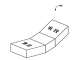
図15は、手動操作により動力分配機構16の差動状態と非差動状態(ロック状態)すなわち変速機構10の無段変速状態と有段変速状態との切換えを選択するための変速状態手動選択装置としてのシーソー型スイッチ44(以下、スイッチ44と表す)の一例でありユーザにより手動操作可能に車両に備えられている。このスイッチ44は、ユーザが所望する変速状態での車両走行を選択可能とするものであり、無段変速走行に対応するスイッチ44の無段と表示された無段変速走行指令釦或いは有段変速走行に対応する有段と表示された有段変速走行指令釦がユーザにより押されることで、それぞれ無段変速走行すなわち変速機構10を電気的な無段変速機として作動可能な無段変速状態とするか、或いは有段変速走行すなわち変速機構10を有段変速機として作動可能な有段変速状態とするかが選択可能とされる。   FIG. 15 shows manual selection of a shift state for selecting switching between a differential state and a non-differential state (locked state) of the power distribution mechanism 16, that is, a stepless speed change state and a stepped speed change state of the speed change mechanism 10. This is an example of a seesaw type switch 44 (hereinafter referred to as a switch 44) as an apparatus, and is provided in a vehicle so that it can be manually operated by a user. This switch 44 allows the user to select vehicle travel in a speed change state desired by the user. The switch 44 corresponding to continuously variable speed travel indicates a continuously variable speed travel command button or stepped speed variable. When the user presses the step-variable speed change command button displayed as stepped corresponding to the travel, the stepless speed change traveling state, that is, the stepless speed change state in which the speed change mechanism 10 can be operated as an electric continuously variable transmission, It is possible to select whether to make a stepped speed change, that is, a stepped speed change state in which the speed change mechanism 10 can operate as a stepped transmission.

前述の実施例では、例えば図6の関係図から車両状態の変化に基づく変速機構10の変速状態の自動切換制御作動を説明したが、その自動切換制御作動に替えて或いは加えて例えばスイッチ44が手動操作されたことにより変速機構10の変速状態が手動切換制御される。つまり、切換制御手段50は、スイッチ44の無段変速状態とするか或いは有段変速状態とするかの選択操作に従って優先的に変速機構10を無段変速状態と有段変速状態とに切り換える。例えば、ユーザは無段変速機のフィーリングや燃費改善効果が得られる走行を所望すれば変速機構10が無段変速状態とされるように手動操作により選択する。またユーザは有段変速機の変速に伴うリズミカルなエンジン回転速度Nの変化を所望すれば変速機構10が有段変速状態とされるように手動操作により選択する。 In the above-described embodiment, for example, the automatic switching control operation of the shift state of the transmission mechanism 10 based on the change of the vehicle state has been described from the relationship diagram of FIG. 6, but the switch 44 is replaced or added to the automatic switching control operation, for example. As a result of manual operation, the shift state of the transmission mechanism 10 is manually switched. In other words, the switching control means 50 preferentially switches the transmission mechanism 10 between the continuously variable transmission state and the continuously variable transmission state in accordance with the selection operation of the switch 44 for the continuously variable transmission state or the stepped transmission state. For example, if the user desires a travel that can achieve the feeling of the continuously variable transmission and the fuel efficiency improvement effect, the user selects the transmission mechanism 10 by manual operation so as to be in a continuously variable transmission state. The user selects by a manual operation as the transmission mechanism 10, if desired to change the rhythmic engine rotational speed N E due to the shifting of the stepped transmission is placed in the step-variable shifting state.

また、スイッチ44に無段変速走行或いは有段変速走行の何れも選択されない状態である中立位置が設けられる場合には、スイッチ44がその中立位置の状態であるときすなわちユーザによって所望する変速状態が選択されていないときや所望する変速状態が自動切換のときには、変速機構10の変速状態の自動切換制御作動が実行されればよい。   Further, when the switch 44 is provided with a neutral position in which neither continuously variable speed traveling nor stepped speed variable traveling is selected, when the switch 44 is in the neutral position, that is, the speed change state desired by the user is determined. When it is not selected or when the desired shift state is automatic switching, the automatic shift control operation of the shift state of the transmission mechanism 10 may be executed.

以上、本発明の実施例を図面に基づいて詳細に説明したが、本発明はその他の態様においても適用される。   As mentioned above, although the Example of this invention was described in detail based on drawing, this invention is applied also in another aspect.

例えば、前述の実施例の図10に示すフローチャートのステップS3(エンジン回転制御手段84或いは電動機制御手段86)にて実行されるエンジン回転速度Nの回転制御、或いは差動部11を中立状態とする制御により、シフトレバー48の非駆動ポジションから駆動ポジションへ切換えに伴う第1クラッチC1および/または第2クラッチC2の耐久性低下が抑制されたり、或いはそれに加えて切換ショックが抑制される効果は得られるので、図10のフローチャートのステップS6(伝達部材回転制御手段88)における第1電動機M1および/または第2電動機M2を用いた第2電動機回転速度NM2の同期制御は実行されなくとも本実施例は適用され得る。 For example, a neutral state rotation control, or the differential portion 11 of the engine rotation speed N E to be executed in the flow chart of step S3 shown in FIG. 10 of the foregoing embodiment (engine control unit 84 or the motor control means 86) This control suppresses a decrease in durability of the first clutch C1 and / or the second clutch C2 due to switching of the shift lever 48 from the non-driving position to the driving position, or in addition to this, the effect of suppressing the switching shock. Therefore, even if the synchronous control of the second motor rotation speed NM2 using the first motor M1 and / or the second motor M2 in step S6 (transmission member rotation control means 88) of the flowchart of FIG. Embodiments can be applied.

また、上記ステップS6が実行されない場合や第2電動機回転速度NM2の同期制御が完了していない場合等には、図10のフローチャートのステップS7(有段変速制御手段54)において、第1クラッチC1および/または第2クラッチC2の油圧をファーストアプライするのではなく漸増(すなわち良く知られた過渡の係合圧制御)しても良い。このようにすれば、その第1クラッチC1および/または第2クラッチC2の油圧がファーストアプライされることに比較して円滑にトルクが伝達され、或いはそれに加えて切換ショックが抑制される。但し、差動部11が中立状態とされている場合には、第1クラッチC1および/または第2クラッチC2の油圧をファーストアプライしても上記切換えに伴う切換ショックが抑制される効果は得られる。 Further, when step S6 is not executed or when the synchronous control of the second motor rotation speed NM2 is not completed, the first clutch is set at step S7 (stepped transmission control means 54) in the flowchart of FIG. The hydraulic pressure of C1 and / or the second clutch C2 may be gradually increased (that is, well-known transient engagement pressure control) instead of being first applied. In this way, torque is transmitted more smoothly than when the hydraulic pressure of the first clutch C1 and / or the second clutch C2 is first applied, or in addition, the switching shock is suppressed. However, when the differential portion 11 is in the neutral state, the effect of suppressing the switching shock accompanying the switching can be obtained even if the hydraulic pressure of the first clutch C1 and / or the second clutch C2 is first applied. .

また、前記ステップS3(エンジン回転制御手段84)におけるエンジン回転速度Nの回転制御は、シフトレバー48のシフトポジションが「N」ポジション或いは「P」ポジションである場合に実行されたが、ユーザが車両の停止状態においてエンジン8のレーシング(吹き上げ)を実行したい場合も想定されるため例えばシフトポジションが「P」ポジションである場合には、エンジン回転速度Nを所定エンジン回転速度N’以上とならないように制限しなくとも良い。言い換えれば、「P」ポジションの場合はエンジン8のレーシングを許可してエンジン8のレーシングを禁止しなくとも良い。 Further, rotation control of the engine speed N E at the step S3 (the engine rotation control means 84) is a shift position of the shift lever 48 is performed if "N" position or the "P" position, the user If for example, the shift position since the envisaged if you want to run the engine 8 racing (blow) in the stop state of the vehicle is "P" position, the engine rotational speed N E of the predetermined engine rotational speed N E 'more and You don't have to restrict it. In other words, in the “P” position, the racing of the engine 8 may be permitted and the racing of the engine 8 may not be prohibited.

また、前述の実施例の図10に示すフローチャートでは、ステップS1の判断が肯定された場合にはステップS2が実行される前に図示しないステップ(切換制御手段50)にて動力分配機構16が差動状態とされたが、少なくともステップS3或いはS4(電動機制御手段86)にて差動部11を中立状態とする制御が実行されるときに動力分配機構16が差動状態とされればよい。   In the flowchart shown in FIG. 10 of the above-described embodiment, when the determination in step S1 is affirmative, the power distribution mechanism 16 is not connected in a step (switch control means 50) (not shown) before step S2 is executed. The power distribution mechanism 16 only needs to be set to the differential state when the control for setting the differential unit 11 to the neutral state is executed at least in step S3 or S4 (motor control means 86).

また、前述の実施例の変速機構10、70は、差動部11が無段変速状態と定変速状態とに切り換えられることで電気的な無段変速機として機能する無段変速状態と有段変速機として機能する有段変速状態とに切り換え可能に構成されていたが、有段変速状態に切換可能に構成されない変速機構すなわち差動部11が切換クラッチC0および切換ブレーキB0を備えず電気的な無段変速機(電気的な差動装置)としての機能のみを有する差動部11であっても本実施例は適用され得る。   Further, the speed change mechanisms 10 and 70 of the above-described embodiments have a stepless speed change state and a step speed which function as an electric stepless transmission by switching the differential portion 11 between a stepless speed change state and a constant speed change state. Although it is configured to be able to switch to a stepped speed change function that functions as a transmission, the speed change mechanism that is not configured to be switchable to the stepped speed change state, that is, the differential unit 11 does not include the switching clutch C0 and the switching brake B0 and is electrically The present embodiment can be applied even to the differential unit 11 having only a function as a continuously variable transmission (electrical differential device).

また、前述の実施例の変速機構10、70は、差動部11(動力分配機構16)が電気的な無段変速機として作動可能な差動状態とそれを非作動とする非差動状態(ロック状態)とに切り換えられることで無段変速状態と有段変速状態とに切り換え可能に構成され、この無段変速状態と有段変速状態との切換えは差動部11が差動状態と非差動状態とに切換えられることによって行われていたが、例えば差動部11が差動状態のままであっても差動部11の変速比を連続的ではなく段階的に変化させることにより有段変速機として機能させられ得る。言い換えれば、差動部11の差動状態/非差動状態と、変速機構10、70の無段変速状態/有段変速状態とは必ずしも一対一の関係にある訳ではないので、差動部11は必ずしも無段変速状態と有段変速状態とに切換可能に構成される必要はなく、変速機構10、70(差動部11、動力分配機構16)が差動状態と非差動状態とに切換え可能に構成されれば本発明は適用され得る。   Further, in the transmission mechanisms 10 and 70 of the above-described embodiment, a differential state in which the differential unit 11 (power distribution mechanism 16) can operate as an electric continuously variable transmission and a non-differential state in which it is not operated By switching to the (locked state), it is possible to switch between a continuously variable transmission state and a stepped gear shifting state. Although it was performed by switching to the non-differential state, for example, even if the differential unit 11 remains in the differential state, by changing the gear ratio of the differential unit 11 stepwise instead of continuously. It can be made to function as a stepped transmission. In other words, the differential state / non-differential state of the differential unit 11 and the continuously variable transmission state / stepped transmission state of the transmission mechanisms 10 and 70 are not necessarily in a one-to-one relationship. 11 is not necessarily configured to be switchable between a continuously variable transmission state and a stepped transmission state, and the transmission mechanisms 10 and 70 (the differential unit 11 and the power distribution mechanism 16) are in a differential state and a non-differential state. The present invention can be applied if it is configured to be switchable.

また、前述の実施例では、動力伝達経路を、動力伝達可能状態と動力伝達遮断状態とに選択的に切り換える係合装置として自動変速部20、72の一部を構成する第1クラッチC1および第2クラッチC2が用いられ、その第1クラッチC1および第2クラッチC2は自動変速部20、72と差動部11との間に配設されていたが、必ずしも第1クラッチC1および第2クラッチC2である必要はなく動力伝達可能状態と動力伝達遮断状態とに動力伝達経路を選択的に切り換えられれる係合装置が少なくとも1つ備えられておればよい。例えばその係合装置は出力軸22に連結されていてもよいし自動変速部20、72内の回転部材に連結されていてもよい。また、上記係合装置は自動変速部20、72の一部を構成する必要もなく自動変速部20、72とは別に備えられてもよい。   Further, in the above-described embodiment, the first clutch C1 and the first clutch C1 that constitute a part of the automatic transmission units 20 and 72 as an engagement device that selectively switches the power transmission path between the power transmission enabled state and the power transmission cut-off state. Two clutches C2 are used, and the first clutch C1 and the second clutch C2 are disposed between the automatic transmission units 20 and 72 and the differential unit 11, but are not necessarily limited to the first clutch C1 and the second clutch C2. It is not necessary that the power transmission path be selectively switched between the power transmission enabled state and the power transmission cut-off state, as long as at least one engagement device is provided. For example, the engaging device may be connected to the output shaft 22 or may be connected to a rotating member in the automatic transmission units 20 and 72. Further, the engaging device does not need to form part of the automatic transmission units 20 and 72 and may be provided separately from the automatic transmission units 20 and 72.

また、前述の実施例の動力分配機構16では、第1キャリヤCA1がエンジン8に連結され、第1サンギヤS1が第1電動機M1に連結され、第1リングギヤR1が伝達部材18に連結されていたが、それらの連結関係は、必ずしもそれに限定されるものではなく、エンジン8、第1電動機M1、伝達部材18は、第1遊星歯車装置24の3要素CA1、S1、R1のうちのいずれと連結されていても差し支えない。   In the power distribution mechanism 16 of the above-described embodiment, the first carrier CA1 is connected to the engine 8, the first sun gear S1 is connected to the first electric motor M1, and the first ring gear R1 is connected to the transmission member 18. However, the connection relationship is not necessarily limited thereto, and the engine 8, the first electric motor M1, and the transmission member 18 are connected to any of the three elements CA1, S1, and R1 of the first planetary gear device 24. It can be done.

また、前述の実施例では、エンジン8は入力軸14と直結されていたが、例えばギヤ、ベルト等を介して作動的に連結されておればよく、共通の軸心上に配置される必要もない。   In the above-described embodiment, the engine 8 is directly connected to the input shaft 14. However, the engine 8 only needs to be operatively connected via, for example, a gear, a belt, or the like, and needs to be disposed on a common shaft center. Absent.

また、前述の実施例では、第1電動機M1および第2電動機M2は、入力軸14に同心に配置されて第1電動機M1は第1サンギヤS1に連結され第2電動機M2は伝達部材18に連結されていたが、必ずしもそのように配置される必要はなく、例えばギヤ、ベルト等を介して作動的に第1電動機M1は第1サンギヤS1に連結され、第2電動機M2は伝達部材18に連結されてもよい。   In the above-described embodiment, the first motor M1 and the second motor M2 are arranged concentrically with the input shaft 14, the first motor M1 is connected to the first sun gear S1, and the second motor M2 is connected to the transmission member 18. However, it is not necessarily arranged as such, and for example, the first electric motor M1 is operatively connected to the first sun gear S1 and the second electric motor M2 is connected to the transmission member 18 through a gear, a belt, or the like. May be.

また、前述の動力分配機構16には切換クラッチC0および切換ブレーキB0が備えられていたが、切換クラッチC0および切換ブレーキB0は必ずしも両方備えられる必要はない。また、上記切換クラッチC0は、サンギヤS1とキャリヤCA1とを選択的に連結するものであったが、サンギヤS1とリングギヤR1との間や、キャリヤCA1とリングギヤR1との間を選択的に連結するものであってもよい。要するに、第1遊星歯車装置24の3要素のうちのいずれか2つを相互に連結するものであればよい。   In addition, although the power distribution mechanism 16 is provided with the switching clutch C0 and the switching brake B0, both the switching clutch C0 and the switching brake B0 are not necessarily provided. The switching clutch C0 selectively connects the sun gear S1 and the carrier CA1, but selectively connects the sun gear S1 and the ring gear R1 or between the carrier CA1 and the ring gear R1. It may be a thing. In short, what is necessary is just to connect any two of the three elements of the first planetary gear unit 24 to each other.

また、前述の実施例の変速機構10、70では、ニュートラル「N」とする場合には切換クラッチC0が係合されていたが、必ずしも係合される必要はない。   Further, in the transmission mechanisms 10 and 70 of the above-described embodiment, the switching clutch C0 is engaged when the neutral "N" is set, but it is not always necessary to be engaged.

また、前述の実施例では、切換クラッチC0および切換ブレーキB0などの油圧式摩擦係合装置は、パウダー(磁粉)クラッチ、電磁クラッチ、噛み合い型のドグクラッチなどの磁粉式、電磁式、機械式係合装置から構成されていてもよい。   In the above-described embodiments, the hydraulic friction engagement devices such as the switching clutch C0 and the switching brake B0 are magnetic powder type, electromagnetic type, mechanical type engagement such as powder (magnetic powder) clutch, electromagnetic clutch, and meshing type dog clutch. You may be comprised from the apparatus.

また、前述の実施例では、第2電動機M2が伝達部材18に連結されていたが、出力軸22に連結されていてもよいし、自動変速部20、72内の回転部材に連結されていてもよい。   In the above-described embodiment, the second electric motor M2 is connected to the transmission member 18. However, the second electric motor M2 may be connected to the output shaft 22, or may be connected to a rotating member in the automatic transmission units 20 and 72. Also good.

また、前述の実施例では、差動部11すなわち動力分配機構16の出力部材である伝達部材18と駆動輪38との間の動力伝達経路に、自動変速部20、72が介装されていたが、例えば自動変速機の一種である無段変速機(CVT)、手動変速機としてよく知られた常時噛合式平行2軸型ではあるがセレクトシリンダおよびシフトシリンダによりギヤ段が自動的に切換られることが可能な自動変速機、手動操作により変速段が切り換えられる同期噛み合い式の手動変速機等の他の形式の動力伝達装置(変速機)が設けられていてもよい。その無段変速機(CVT)の場合には、動力分配機構16が定変速状態とされることで全体として有段変速状態とされる。有段変速状態とは、電気パスを用いないで専ら機械的伝達経路で動力伝達することである。或いは、上記無段変速機は有段変速機における変速段に対応するように予め複数の固定された変速比が記憶され、その複数の固定された変速比を用いて自動変速部20、72の変速が実行されてもよい。或いは、自動変速部20、72は必ずしも備えられてなくとも本発明は適用され得る。この場合のように自動変速部20、72が無段変速機(CVT)や常時噛合式変速機等である場合、或いは自動変速部20、72が備えられない場合には、伝達部材18と駆動輪38との動力伝達経路に係合装置が単独で備えられその係合装置の係合と解放とを制御することで動力伝達経路が動力伝達可能状態と動力伝達遮断状態とに切り換えられる。   In the above-described embodiment, the automatic transmission units 20 and 72 are interposed in the power transmission path between the differential member 11, that is, the transmission member 18 that is the output member of the power distribution mechanism 16 and the drive wheel 38. However, for example, a continuously variable transmission (CVT), which is a kind of automatic transmission, and a continuously meshing parallel two-shaft type well known as a manual transmission, the gear stage is automatically switched by a select cylinder and a shift cylinder. Other types of power transmission devices (transmissions) may be provided, such as an automatic transmission that can be operated, and a synchronous mesh type manual transmission in which the gear position is switched by manual operation. In the case of the continuously variable transmission (CVT), the power distribution mechanism 16 is brought into a constant speed change state, whereby the stepped speed change state is made as a whole. The stepped speed change state means that power is transmitted exclusively through a mechanical transmission path without using an electric path. Alternatively, in the continuously variable transmission, a plurality of fixed gear ratios are stored in advance so as to correspond to the gear positions in the stepped transmission, and the automatic transmission units 20 and 72 are used by using the plurality of fixed gear ratios. Shifting may be performed. Alternatively, the present invention can be applied even if the automatic transmission units 20 and 72 are not necessarily provided. When the automatic transmission units 20 and 72 are continuously variable transmissions (CVT), a constant mesh transmission, or the like as in this case, or when the automatic transmission units 20 and 72 are not provided, the transmission member 18 and the drive are driven. An engagement device is provided alone in the power transmission path with the wheel 38, and the power transmission path is switched between a power transmission enable state and a power transmission cutoff state by controlling engagement and release of the engagement device.

また、前述の実施例では、自動変速部20、72は伝達部材18を介して差動部11と直列に連結されていたが、入力軸14と平行にカウンタ軸が設けられそのカウンタ軸上に同心に自動変速部20、72が配設されてもよい。この場合には、差動部11と自動変速部20、72とは、例えば伝達部材18としてのカウンタギヤ対、スプロケットおよびチェーンで構成される1組の伝達部材などを介して動力伝達可能に連結される。   In the above-described embodiment, the automatic transmission units 20 and 72 are connected in series with the differential unit 11 via the transmission member 18, but a counter shaft is provided in parallel with the input shaft 14 and is on the counter shaft. The automatic transmission units 20 and 72 may be arranged concentrically. In this case, the differential unit 11 and the automatic transmission units 20 and 72 are connected so as to be able to transmit power via, for example, a pair of transmission members composed of a counter gear pair as a transmission member 18, a sprocket and a chain, and the like. Is done.

また、前述の実施例の差動機構としての動力分配機構16は、例えばエンジンによって回転駆動されるピニオンと、そのピニオンに噛み合う一対のかさ歯車が第1電動機M1および第2電動機M2に作動的に連結された差動歯車装置であってもよい。   Further, the power distribution mechanism 16 as the differential mechanism of the above-described embodiment is configured such that, for example, a pinion rotated by an engine and a pair of bevel gears meshing with the pinion are operatively connected to the first electric motor M1 and the second electric motor M2. A connected differential gear device may be used.

また、前述の実施例の動力分配機構16は、1組の遊星歯車装置から構成されていたが、2以上の遊星歯車装置から構成されて、非差動状態(定変速状態)では3段以上の変速機として機能するものであってもよい。   In addition, the power distribution mechanism 16 of the above-described embodiment is composed of one set of planetary gear devices, but is composed of two or more planetary gear devices, and has three or more stages in the non-differential state (constant speed change state). It may function as a transmission.

また、前述の実施例の切換装置46は、複数種類のシフトポジションを選択するために操作されるシフトレバー48を備えていたが、そのシフトレバー48に替えて、例えば押しボタン式のスイッチやスライド式スイッチ等の複数種類のシフトポジションを選択可能なスイッチ、或いは手動操作に因らず運転者の音声に反応して複数種類のシフトポジションを切り換えられる装置や足の操作により複数種類のシフトポジションを切り換えられる装置等であってもよい。また、シフトレバー48が「M」ポジションへ操作されることにより、変速レンジが設定されるものであったが変速段が設定されることすなわち各変速レンジの最高速変速段が変速段として設定されてもよい。この場合、自動変速部20、72では変速段が切り換えられて変速が実行される。例えば、シフトレバー48が「M」ポジションにおけるアップシフト位置「+」またはダウンシフト位置「−」へ手動操作されると、自動変速部20では第1速ギヤ段乃至第4速ギヤ段の何れかがシフトレバー48の操作に応じて設定される。   The switching device 46 of the above-described embodiment includes the shift lever 48 that is operated to select a plurality of types of shift positions. Instead of the shift lever 48, for example, a push button switch or a slide A switch that can select multiple types of shift positions, such as a type switch, or a device that can switch between multiple types of shift positions in response to the driver's voice regardless of manual operation, or multiple types of shift positions by foot operation It may be a device that can be switched. Further, when the shift lever 48 is operated to the “M” position, the shift range is set, but the shift speed is set, that is, the highest speed shift speed of each shift range is set as the shift speed. May be. In this case, in the automatic transmission units 20 and 72, the gear position is switched and the gear shift is executed. For example, when the shift lever 48 is manually operated to the upshift position “+” or the downshift position “−” in the “M” position, the automatic transmission unit 20 selects any one of the first to fourth gears. Is set according to the operation of the shift lever 48.

また、前述の実施例のスイッチ44はシーソー型のスイッチであったが、例えば押しボタン式のスイッチ、択一的にのみ押した状態が保持可能な2つの押しボタン式のスイッチ、レバー式スイッチ、スライド式スイッチ等の少なくとも無段変速走行(差動状態)と有段変速走行(非差動状態)とが択一的に切り換えられるスイッチであればよい。また、スイッチ44に中立位置が設けられる場合にその中立位置に替えて、スイッチ44の選択状態を有効或いは無効すなわち中立位置相当が選択可能なスイッチがスイッチ44とは別に設けられてもよい。また、スイッチ44に替えて或いは加えて、手動操作に因らず運転者の音声に反応して少なくとも無段変速走行(差動状態)と有段変速走行(非差動状態)とが択一的に切り換えられる装置や足の操作により切り換えられる装置等であってもよい。   In addition, the switch 44 of the above-described embodiment is a seesaw type switch. For example, a push button type switch, two push button type switches that can be held only alternatively, a lever type switch, Any switch that can selectively switch between at least continuously variable speed travel (differential state) and stepped speed variable travel (non-differential state), such as a slide switch. In addition, when the switch 44 is provided with a neutral position, a switch capable of selecting whether the selection state of the switch 44 is valid or invalid, that is, equivalent to the neutral position, may be provided separately from the switch 44 instead of the neutral position. Further, instead of or in addition to the switch 44, at least continuously variable speed travel (differential state) and stepped speed variable travel (non-differential state) are selected in response to the driver's voice regardless of manual operation. For example, a device that can be switched automatically or a device that can be switched by operating a foot may be used.

なお、上述したのはあくまでも一実施形態であり、本発明は当業者の知識に基づいて種々の変更、改良を加えた態様で実施することができる。   The above description is only an embodiment, and the present invention can be implemented in variously modified and improved forms based on the knowledge of those skilled in the art.

本発明の一実施例であるハイブリッド車両の駆動装置の構成を説明する骨子図である。BRIEF DESCRIPTION OF THE DRAWINGS FIG. 1 is a skeleton diagram illustrating a configuration of a hybrid vehicle drive device according to an embodiment of the present invention. 図1の実施例のハイブリッド車両の駆動装置が無段或いは有段変速作動させられる場合における変速作動とそれに用いられる油圧式摩擦係合装置の作動の組み合わせとの関係を説明する作動図表である。2 is an operation chart for explaining the relationship between a speed change operation and a combination of operations of a hydraulic friction engagement device used therefor when the hybrid vehicle drive device of the embodiment of FIG. 図1の実施例のハイブリッド車両の駆動装置が有段変速作動させられる場合における各ギヤ段の相対的回転速度を説明する共線図である。FIG. 2 is a collinear diagram illustrating a relative rotational speed of each gear stage when the hybrid vehicle drive device of the embodiment of FIG. 図1の実施例の駆動装置に設けられた電子制御装置の入出力信号を説明する図である。It is a figure explaining the input-output signal of the electronic controller provided in the drive device of the Example of FIG. 図4の電子制御装置の制御作動の要部を説明する機能ブロック線図である。It is a functional block diagram explaining the principal part of the control action of the electronic controller of FIG. 車速と出力トルクとをパラメータとする同じ二次元座標に構成された、自動変速部の変速判断の基となる予め記憶された変速線図と変速機構の変速状態の切換判断の基となる予め記憶された切換線図との関係を示す図である。A pre-stored shift diagram based on the same two-dimensional coordinates having the vehicle speed and the output torque as parameters, and a pre-stored shift diagram as a basis for the shift determination of the automatic transmission unit and a shift determination of the shift state of the transmission mechanism It is a figure which shows the relationship with the made switching diagram. 無段制御領域と有段制御領域との境界線を有する予め記憶された関係を示す図であって、図6の破線に示す無段制御領域と有段制御領域との境界をマップ化するための概念図でもある。FIG. 7 is a diagram showing a pre-stored relationship having a boundary line between a stepless control region and a stepped control region, in order to map the boundary between the stepless control region and the stepped control region indicated by a broken line in FIG. 6. It is also a conceptual diagram. 有段式変速機におけるアップシフトに伴うエンジン回転速度の変化の一例である。It is an example of the change of the engine rotational speed accompanying the upshift in a stepped transmission. 複数種類のシフトポジションを選択するために操作される切換装置の一例である。It is an example of the switching device operated in order to select multiple types of shift positions. 図5の電子制御装置の制御作動すなわちシフトレバーが非駆動ポジションにあるときにエンジンが作動している場合においてシフトレバーが非駆動ポジションから駆動ポジションへ操作された際の第1クラッチおよび/または第2クラッチの耐久性の低下を抑制するための差動部の制御作動を説明するフローチャートである。The first clutch and / or the first clutch when the shift lever is operated from the non-driving position to the driving position in the case of the control operation of the electronic control unit of FIG. 5, that is, when the engine is operating when the shift lever is in the non-driving position. It is a flowchart explaining the control action of the differential part for suppressing the fall of durability of 2 clutches. 図10のフローチャートに示す制御作動を説明するタイムチャートである。It is a time chart explaining the control action shown in the flowchart of FIG. 本発明の他の実施例におけるハイブリッド車両の駆動装置の構成を説明する骨子図であって、図1に相当する図である。FIG. 3 is a skeleton diagram illustrating a configuration of a drive device for a hybrid vehicle according to another embodiment of the present invention, corresponding to FIG. 1. 図12の実施例のハイブリッド車両の駆動装置が無段或いは有段変速作動させられる場合における変速作動とそれに用いられる油圧式摩擦係合装置の作動の組み合わせとの関係を説明する作動図表であって、図2に相当する図である。FIG. 13 is an operation chart for explaining the relationship between the speed change operation and the operation of the hydraulic friction engagement device used in the case where the drive device of the hybrid vehicle of the embodiment of FIG. FIG. 3 is a diagram corresponding to FIG. 2. 図12の実施例のハイブリッド車両の駆動装置が有段変速作動させられる場合における各ギヤ段の相対的回転速度を説明する共線図であって、図3に相当する図である。FIG. 13 is a collinear diagram illustrating the relative rotational speeds of the respective gear stages when the hybrid vehicle drive device of the embodiment of FIG. 切換装置としてのシーソー型スイッチであって変速状態を選択するためにユーザによって操作される変速状態手動選択装置の一例である。It is a seesaw type switch as a switching device, and is an example of a shift state manual selection device operated by a user to select a shift state.

符号の説明Explanation of symbols

8:エンジン
10、70:変速機構(駆動装置)
11:差動部
16:動力分配機構(差動機構)
18:伝達部材
20、72:自動変速部(変速部)
38:駆動輪
46:切換装置
84:エンジン回転制御手段
86:電動機制御手段
M1:第1電動機
M2:第2電動機
C0:切換クラッチ(差動状態切換装置)
B0:切換ブレーキ(差動状態切換装置)
C1:第1クラッチ(係合装置)
C2:第2クラッチ(係合装置)
8: Engine 10, 70: Transmission mechanism (drive device)
11: Differential unit 16: Power distribution mechanism (differential mechanism)
18: Transmission member 20, 72: Automatic transmission unit (transmission unit)
38: Drive wheel 46: Switching device 84: Engine rotation control means 86: Electric motor control means M1: First electric motor M2: Second electric motor C0: Switching clutch (differential state switching device)
B0: Switching brake (Differential state switching device)
C1: First clutch (engagement device)
C2: Second clutch (engagement device)

Claims (5)

エンジンの出力を第1電動機および伝達部材へ分配する差動機構と該伝達部材から駆動輪への動力伝達経路に設けられた第2電動機とを有する差動部と、前記動力伝達経路の一部を構成し変速機として機能する変速部とを備えた車両用駆動装置の制御装置であって、
前記エンジンから前記駆動輪への動力伝達経路を、動力伝達可能状態と動力伝達遮断状態とに選択的に切り換える係合装置と、
該係合装置による前記動力伝達可能状態への切換えを選択するための駆動ポジションと該係合装置による前記動力伝達遮断状態への切換えを選択するための非駆動ポジションとに切り換える切換装置と、
該切換装置が前記非駆動ポジションへ切り換えられているときには、前記エンジンの回転速度が所定エンジン回転速度以上とならないように回転制御するエンジン回転制御手段と
を、含むことを特徴とする車両用駆動装置の制御装置。
A differential mechanism having a differential mechanism that distributes the output of the engine to the first motor and the transmission member; and a second motor provided in a power transmission path from the transmission member to the drive wheels; and a part of the power transmission path And a control device for a vehicle drive device including a speed change unit that functions as a transmission,
An engagement device that selectively switches a power transmission path from the engine to the drive wheel between a power transmission enable state and a power transmission cutoff state;
A switching device for switching between a driving position for selecting switching to the power transmission enabled state by the engagement device and a non-driving position for selecting switching to the power transmission cutoff state by the engagement device;
An engine rotation control means for controlling the rotation of the engine so that the rotation speed of the engine does not exceed a predetermined engine rotation speed when the switching device is switched to the non-driving position. Control device.
前記エンジン回転制御手段は、エンジンの出力を制御することにより前記エンジンの回転速度が所定エンジン回転速度以上とならないように回転制御するものであり、
前記切換装置が前記非駆動ポジションへ切り換えられているときには、前記第1電動機および前記第2電動機を無負荷状態とする電動機制御手段を更に含むものである請求項1の車両用駆動装置の制御装置。
The engine rotation control means controls the rotation of the engine so that the rotation speed of the engine does not exceed a predetermined engine rotation speed by controlling the output of the engine,
2. The vehicle drive device control device according to claim 1, further comprising electric motor control means for placing the first electric motor and the second electric motor in a no-load state when the switching device is switched to the non-drive position.
エンジンの出力を第1電動機および伝達部材へ分配する差動機構と該伝達部材から駆動輪への動力伝達経路に設けられた第2電動機とを有する差動部と、前記動力伝達経路の一部を構成し変速機として機能する変速部とを備えた車両用駆動装置の制御装置であって、
前記エンジンから前記駆動輪への動力伝達経路を、動力伝達可能状態と動力伝達遮断状態とに選択的に切り換える係合装置と、
該係合装置による前記動力伝達可能状態への切換えを選択するための駆動ポジションと該係合装置による前記動力伝達遮断状態への切換えを選択するための非駆動ポジションとに切り換える切換装置と、
該切換装置が前記非駆動ポジションへ切り換えられているときには、前記第1電動機および前記第2電動機を無負荷状態とする電動機制御手段と
を、含むことを特徴とする車両用駆動装置の制御装置。
A differential mechanism having a differential mechanism that distributes the output of the engine to the first motor and the transmission member; and a second motor provided in a power transmission path from the transmission member to the drive wheels; and a part of the power transmission path And a control device for a vehicle drive device including a speed change unit that functions as a transmission,
An engagement device that selectively switches a power transmission path from the engine to the drive wheel between a power transmission enable state and a power transmission cutoff state;
A switching device for switching between a driving position for selecting switching to the power transmission enabled state by the engagement device and a non-driving position for selecting switching to the power transmission cutoff state by the engagement device;
A control device for a vehicle drive device, comprising: motor control means for placing the first motor and the second motor in a no-load state when the switching device is switched to the non-drive position.
前記変速部は有段式自動変速機であるとともに、前記係合装置は該有段式自動変速機の変速段を成立させるために用いられるものであり、
前記切換装置が前記非駆動ポジションへ切り換えられているときには、該係合装置により該有段式自動変速機が動力伝達遮断状態とされるものである請求項1乃至3のいずれかの車両用駆動装置の制御装置。
The transmission unit is a stepped automatic transmission, and the engagement device is used to establish a shift stage of the stepped automatic transmission,
The vehicle drive according to any one of claims 1 to 3, wherein when the switching device is switched to the non-driving position, the stepped automatic transmission is in a power transmission cut-off state by the engagement device. Control device for the device.
前記差動機構は、該差動機構を差動状態とロック状態とに選択的に切り換えるための差動状態切換装置を備え、
前記切換装置が前記非駆動ポジションへ切り換えられているときには、前記差動状態切換装置により前記差動機構が差動状態とされるものである請求項1乃至4のいずれかの車両用駆動装置の制御装置。
The differential mechanism includes a differential state switching device for selectively switching the differential mechanism between a differential state and a locked state,
5. The vehicle drive device according to claim 1, wherein when the switching device is switched to the non-driving position, the differential mechanism is brought into a differential state by the differential state switching device. Control device.
JP2004293795A 2004-10-06 2004-10-06 Controller for vehicle drive unit Pending JP2006103541A (en)

Priority Applications (1)

Application Number Priority Date Filing Date Title
JP2004293795A JP2006103541A (en) 2004-10-06 2004-10-06 Controller for vehicle drive unit

Applications Claiming Priority (1)

Application Number Priority Date Filing Date Title
JP2004293795A JP2006103541A (en) 2004-10-06 2004-10-06 Controller for vehicle drive unit

Publications (2)

Publication Number Publication Date
JP2006103541A true JP2006103541A (en) 2006-04-20
JP2006103541A5 JP2006103541A5 (en) 2007-09-06

Family

ID=36373730

Family Applications (1)

Application Number Title Priority Date Filing Date
JP2004293795A Pending JP2006103541A (en) 2004-10-06 2004-10-06 Controller for vehicle drive unit

Country Status (1)

Country Link
JP (1) JP2006103541A (en)

Cited By (4)

* Cited by examiner, † Cited by third party
Publication number Priority date Publication date Assignee Title
WO2008023507A1 (en) * 2006-08-25 2008-02-28 Toyota Jidosha Kabushiki Kaisha Controller of vehicle, hybrid vehicle, control method of vehicle, program for making computer execute control method of vehicle, and computer readable recording medium recording that program
JP2010006224A (en) * 2008-06-26 2010-01-14 Toyota Motor Corp Vehicle and its control method
US10672207B2 (en) 2017-01-20 2020-06-02 Polaris Industries Inc. Diagnostic systems and methods of a continuously variable transmission
CN112078568A (en) * 2019-06-12 2020-12-15 丰田自动车株式会社 Hybrid vehicle

Cited By (8)

* Cited by examiner, † Cited by third party
Publication number Priority date Publication date Assignee Title
WO2008023507A1 (en) * 2006-08-25 2008-02-28 Toyota Jidosha Kabushiki Kaisha Controller of vehicle, hybrid vehicle, control method of vehicle, program for making computer execute control method of vehicle, and computer readable recording medium recording that program
US8170736B2 (en) 2006-08-25 2012-05-01 Toyota Jidosha Kabushiki Kaisha Control device for vehicle, hybrid vehicle, method of controlling vehicle, program for causing computer to execute the method of controlling the vehicle, and computer-readable recording medium recording the program
JP2010006224A (en) * 2008-06-26 2010-01-14 Toyota Motor Corp Vehicle and its control method
US10672207B2 (en) 2017-01-20 2020-06-02 Polaris Industries Inc. Diagnostic systems and methods of a continuously variable transmission
US11430272B2 (en) 2017-01-20 2022-08-30 Polaris Industries Inc. Diagnostic systems and methods of a continuously variable transmission
CN112078568A (en) * 2019-06-12 2020-12-15 丰田自动车株式会社 Hybrid vehicle
JP2020199950A (en) * 2019-06-12 2020-12-17 トヨタ自動車株式会社 Hybrid vehicle
JP7230700B2 (en) 2019-06-12 2023-03-01 トヨタ自動車株式会社 hybrid vehicle

Similar Documents

Publication Publication Date Title
JP4192911B2 (en) Control device for vehicle drive device
JP4244961B2 (en) Control device for vehicle drive device
JP4320650B2 (en) Control device for vehicle drive device
JP4155244B2 (en) Control device for vehicle drive device
JP4320649B2 (en) Control device for vehicle drive device
JP5003220B2 (en) Control device for vehicle drive device
JP4192814B2 (en) Control device for vehicle drive device
JP4438689B2 (en) Control device for vehicle drive device
JP4207920B2 (en) Vehicle drive device
JP4277806B2 (en) Control device for vehicle drive device
JP4438574B2 (en) Control device for vehicle drive device
JP4134954B2 (en) Control device for vehicle drive device
JP4389806B2 (en) Control device for vehicle drive device
JP4410655B2 (en) Control device for vehicle drive device
JP4222294B2 (en) Control device for vehicle drive device
JP4229034B2 (en) Control device for vehicle drive device
JP4107272B2 (en) Control device for vehicle drive device
JP2007001491A (en) Controller for drive unit for vehicle
JP4289242B2 (en) Control device for vehicle drive device
JP4192855B2 (en) Control device for vehicle drive device
JP4471029B2 (en) Control device for vehicle drive device
JP4222291B2 (en) Control device for vehicle drive device
JP2006103541A (en) Controller for vehicle drive unit
JP4293070B2 (en) Control device for vehicle drive device
JP4379526B2 (en) Control device for vehicle drive device

Legal Events

Date Code Title Description
A521 Request for written amendment filed

Free format text: JAPANESE INTERMEDIATE CODE: A523

Effective date: 20070719

A621 Written request for application examination

Free format text: JAPANESE INTERMEDIATE CODE: A621

Effective date: 20070719

A131 Notification of reasons for refusal

Free format text: JAPANESE INTERMEDIATE CODE: A131

Effective date: 20080129

A521 Request for written amendment filed

Free format text: JAPANESE INTERMEDIATE CODE: A523

Effective date: 20080328

A02 Decision of refusal

Free format text: JAPANESE INTERMEDIATE CODE: A02

Effective date: 20080430