JP2006103441A - Tire condition detection device - Google Patents
Tire condition detection device Download PDFInfo
- Publication number
- JP2006103441A JP2006103441A JP2004290955A JP2004290955A JP2006103441A JP 2006103441 A JP2006103441 A JP 2006103441A JP 2004290955 A JP2004290955 A JP 2004290955A JP 2004290955 A JP2004290955 A JP 2004290955A JP 2006103441 A JP2006103441 A JP 2006103441A
- Authority
- JP
- Japan
- Prior art keywords
- tire
- condition detection
- tire condition
- detection device
- receiver
- Prior art date
- Legal status (The legal status is an assumption and is not a legal conclusion. Google has not performed a legal analysis and makes no representation as to the accuracy of the status listed.)
- Granted
Links
Images

Classifications
-
- B—PERFORMING OPERATIONS; TRANSPORTING
- B60—VEHICLES IN GENERAL
- B60C—VEHICLE TYRES; TYRE INFLATION; TYRE CHANGING; CONNECTING VALVES TO INFLATABLE ELASTIC BODIES IN GENERAL; DEVICES OR ARRANGEMENTS RELATED TO TYRES
- B60C23/00—Devices for measuring, signalling, controlling, or distributing tyre pressure or temperature, specially adapted for mounting on vehicles; Arrangement of tyre inflating devices on vehicles, e.g. of pumps or of tanks; Tyre cooling arrangements
- B60C23/02—Signalling devices actuated by tyre pressure
- B60C23/04—Signalling devices actuated by tyre pressure mounted on the wheel or tyre
- B60C23/0408—Signalling devices actuated by tyre pressure mounted on the wheel or tyre transmitting the signals by non-mechanical means from the wheel or tyre to a vehicle body mounted receiver
- B60C23/0422—Signalling devices actuated by tyre pressure mounted on the wheel or tyre transmitting the signals by non-mechanical means from the wheel or tyre to a vehicle body mounted receiver characterised by the type of signal transmission means
- B60C23/0433—Radio signals
- B60C23/0435—Vehicle body mounted circuits, e.g. transceiver or antenna fixed to central console, door, roof, mirror or fender
- B60C23/0444—Antenna structures, control or arrangements thereof, e.g. for directional antennas, diversity antenna, antenna multiplexing or antennas integrated in fenders
-
- B—PERFORMING OPERATIONS; TRANSPORTING
- B60—VEHICLES IN GENERAL
- B60C—VEHICLE TYRES; TYRE INFLATION; TYRE CHANGING; CONNECTING VALVES TO INFLATABLE ELASTIC BODIES IN GENERAL; DEVICES OR ARRANGEMENTS RELATED TO TYRES
- B60C23/00—Devices for measuring, signalling, controlling, or distributing tyre pressure or temperature, specially adapted for mounting on vehicles; Arrangement of tyre inflating devices on vehicles, e.g. of pumps or of tanks; Tyre cooling arrangements
- B60C23/02—Signalling devices actuated by tyre pressure
- B60C23/04—Signalling devices actuated by tyre pressure mounted on the wheel or tyre
- B60C23/0408—Signalling devices actuated by tyre pressure mounted on the wheel or tyre transmitting the signals by non-mechanical means from the wheel or tyre to a vehicle body mounted receiver
- B60C23/0422—Signalling devices actuated by tyre pressure mounted on the wheel or tyre transmitting the signals by non-mechanical means from the wheel or tyre to a vehicle body mounted receiver characterised by the type of signal transmission means
- B60C23/0427—Near field transmission with inductive or capacitive coupling means
- B60C23/0432—Near field transmission with inductive or capacitive coupling means using vehicle structural parts as signal path, e.g. chassis, axle or fender
Landscapes
- Engineering & Computer Science (AREA)
- Mechanical Engineering (AREA)
- Arrangements For Transmission Of Measured Signals (AREA)
- Measuring Fluid Pressure (AREA)
Abstract
Description
本発明は、タイヤ状態検出装置に関し、更に詳しくは、配線作業が容易であり、かつその配線の断線による故障を改善するようにしたタイヤ状態検出装置に関する。 The present invention relates to a tire condition detection device, and more particularly to a tire condition detection device that facilitates wiring work and improves a failure due to disconnection of the wiring.
従来、車両の安全性を高めるため、車両に装着したタイヤの空気圧や温度などの状態を検出するようにした装置が種々提案されている(例えば、特許文献1,2,3参照)。これらのタイヤ状態を検出する装置は、タイヤ側に装着されるセンサ、送信器、送信アンテナと、車両側に装着される受信アンテナ、受信器、表示器等を有しており、センサにより検出した空気圧や温度などのタイヤ状態検出信号を電波により車両側に送信して運転者がタイヤ状態を確認できるようにし、空気圧の減少やタイヤの内部故障による温度上昇などどを早期に発見して、タイヤに起因する車両事故を未然に防ごうとするものである。
Conventionally, in order to improve the safety of a vehicle, various devices have been proposed that detect the state of tires mounted on the vehicle such as air pressure and temperature (see, for example,
ところで、最近、タイヤの空気圧を検出するタイヤ空気圧検出装置などのタイヤ状態検出装置が試験的ではあるが、トラックなどの車両に実際に取り付けられるようになってきている。 By the way, recently, a tire state detection device such as a tire air pressure detection device for detecting the tire air pressure is experimental, but it is actually attached to a vehicle such as a truck.
通常、タイヤ側の送信アンテナと車両側の受信アンテナとの間の通信に使用される電波は、無免許、無届けで使用できるようにするため、電波法規の規制に抵触しない微弱な電波が使用されている。その電波を効率よく受信するため、車両側の受信アンテナは、タイヤ近傍のタイヤハウス内に設置される。 Normally, weak radio waves that do not conflict with radio wave regulations are used so that radio waves used for communication between the transmitting antenna on the tire side and the receiving antenna on the vehicle side can be used without a license. Has been. In order to efficiently receive the radio wave, the receiving antenna on the vehicle side is installed in a tire house near the tire.
他方、受信器は、メンテナンスを容易にするため、表示器などの機器と共に運転席の近傍に配置され、受信アンテナと受信器との間は有線接続にしている。 On the other hand, in order to facilitate maintenance, the receiver is disposed in the vicinity of the driver's seat together with devices such as a display, and the receiving antenna and the receiver are connected by wire.
既存の車両では、その配線の際に作業者が車両の下に潜って配線作業を行うが、特にトラックやバスなどでは、後輪のタイヤハウスに設置した受信アンテナからの配線距離が長いため、配線作業に非常に手間がかかり、それが装置取り付け時の作業性を大きく阻害する原因になっていた。 In existing vehicles, the operator dive underneath the vehicle when wiring, especially for trucks and buses, because the wiring distance from the receiving antenna installed in the tire house on the rear wheel is long, Wiring work is very time-consuming, which has been a major impediment to workability when installing the device.
また、路面に面する車体部分に長く配線されるため、障害物により破損して断線などを引き起こすことがあり、その対策が求められていた。
本発明の目的は、配線作業を容易にし、かつその配線の断線故障を改善することが可能なタイヤ状態検出装置を提供することにある。 An object of the present invention is to provide a tire condition detection device that facilitates wiring work and can improve the disconnection failure of the wiring.
上記目的を達成する本発明は、タイヤ側で検出したタイヤ状態検出信号を車両側で受信アンテナを介して受信し、受信器に入力するようにしたタイヤ状態検出装置において、前記受信アンテナと前記受信器を車両の金属部を介して電気的に接続し、該金属部を導波路として前記受信アンテナで受信したタイヤ状態検出信号を前記受信器に伝送することを特徴とする。 The present invention that achieves the above object includes a tire condition detection device that receives a tire condition detection signal detected on a tire side via a reception antenna on a vehicle side and inputs the signal to a receiver. The tire is electrically connected via a metal part of a vehicle, and the tire condition detection signal received by the receiving antenna is transmitted to the receiver using the metal part as a waveguide.
上述した本発明によれば、受信アンテナから受信器にタイヤ状態検出信号を伝送する導波路として、車両の金属部を使用することにより、受信アンテナから受信器までの配線距離を短くすることができるので、配線作業を容易にすることができる。また、配線距離の減少により配線の断線による故障も低減するため、断線故障の改善も可能になる。 According to the present invention described above, the wiring distance from the receiving antenna to the receiver can be shortened by using the metal part of the vehicle as a waveguide for transmitting the tire condition detection signal from the receiving antenna to the receiver. Therefore, wiring work can be facilitated. In addition, since the failure due to the disconnection of the wiring is reduced by reducing the wiring distance, the disconnection failure can be improved.
以下、本発明の実施の形態について添付の図面を参照しながら詳細に説明する。 Hereinafter, embodiments of the present invention will be described in detail with reference to the accompanying drawings.
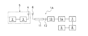
図1は本発明のタイヤ状態検出装置の一実施形態を示し、このタイヤ状態検出装置1Aは、タイヤの空気圧の状態を検出する圧力センサ2と、圧力センサ2で検出した圧力状態検出信号(タイヤ状態検出信号)を送信するための送信器3と送信アンテナ4を備えている。これら圧力センサ2、送信器3及び送信アンテナ4は、タイヤ側装着ユニット5として形成され、図2に示すように、リムRの外周面やタイヤTの内面など、タイヤT側に装着されるようになっている。
FIG. 1 shows an embodiment of a tire condition detection apparatus according to the present invention. This tire condition detection apparatus 1A includes a
タイヤ状態検出装置1Aは、更に、タイヤT側で検出したタイヤの圧力状態検出信号を送信アンテナ4から受信する受信アンテナ6と受信器7、及び受信器7から入力された圧力状態検出信号から圧力値を算出する演算処理器8、演算処理器8で算出した圧力直を表示する表示器9を備えている。
The tire
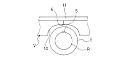
受信アンテナ6は、電波を効率よく受信するため、図2に示すように、車両Vのタイヤハウス10内にタイヤTと対面するようにして設置されるようになっている。受信器7は、装置のメンテナンスを容易にするため、演算処理器8及び表示器9と共に車両Vの運転席の近傍に配置されるようになっている。
The
受信アンテナ6と受信器7との間は、車両Vの金属部11を介して電気的に接続され、金属部11を導波路として受信アンテナ6で受信したタイヤTの圧力状態検出信号を受信器7に伝送するようにしている。このような金属部11としては、シャシー・フレームを好ましく例示することができるが、これに限定されない。
The
受信アンテナ6に電気的に接続された金属部11は、タイヤTの圧力状態検出信号を抽出するためのフィルタ12,13、及びアンプ14を介して受信器7に電気的に接続されている。
The
フィルタ12は、金属部11に接続されたコンデンサから構成され、直流成分を除去し、交流成分だけ通過させるようになっている。フィルタ12に接続されるフィルタ13は、受信アンテナ6で受信した圧力状態検出信号の周波数帯域のみを通過させるバンドパスフィルタから構成され、圧力状態検出信号のみを取り出し可能にしている。フィルタ13で取り出された圧力状態検出信号は、アンプ14を介して受信器7に入力されるようにしてある。
The
上述したタイヤ状態検出装置1Aでは、圧力センサ2で検出したタイヤTの圧力状態検出信号が送信器3と送信アンテナ4を経て受信アンテナ6で受信され、その受信された圧力状態検出信号が金属部11を導波路として伝送される。
In the tire state detection device 1A described above, the pressure state detection signal of the tire T detected by the
次いで、フィルタ12で交流成分のみが通過し、更にその交流成分の信号からフィルタ13で圧力状態検出信号のみが取り出され、それがアンプ14で増幅されて受信器7に入力される。受信器7に入力された圧力状態検出信号は、更に演算処理器8に送られ、そこで圧力値が算出され、その圧力直が表示器9に表示される。
Next, only the AC component passes through the
上述した本発明によれば、受信アンテナ6から受信器7に圧力状態検出信号を伝送する導波路として、シャシー・フレームなどの車両Vの金属部11を使用することで、受信アンテナ6から受信器7までの配線距離を短くすることができる。そのため、配線作業を容易にすることができ、かつ配線距離の減少により断線による故障も低下するので、断線故障も改善することができる。
According to the present invention described above, by using the
図3は、本発明のタイヤ状態検出装置の他の実施形態を示し、このタイヤ状態検出装置1Bは、上述した図1のタイヤ状態検出装置1Aにおいて、圧力状態検出信号のみを抽出するためのフィルタとして、すだれ状電極15aを備えたSAW(Surface Acoustic Wave:弾性表面波)フィルタ15を使用したものである。車両Vの金属部11にSAWフィルタ15が接続され、これにアンプ14を介して受信器7が電気的に接続されている。このにようにSAWフィルタ15を用いて、圧力状態検出信号のみを取り出すようにしてもよい。
FIG. 3 shows another embodiment of the tire condition detection device of the present invention. This tire condition detection device 1B is a filter for extracting only the pressure condition detection signal in the tire condition detection device 1A of FIG. 1 described above. As shown, a SAW (Surface Acoustic Wave)
本発明において、上述した実施形態では、タイヤ状態検出装置として、タイヤTの空気圧の状態を検出する装置を例示したが、タイヤTの温度の状態を温度センサにより検出する装置などであってもよく、本発明のタイヤ状態検出装置は、タイヤ側で圧力や温度などの物理量の状態をセンサで検出し、その検出したタイヤ状態検出信号を車両側で受信アンテナ6を介して受信し、受信器7に入力するようにした装置であれば、いずれのタイヤ状態検出装置であってもよい。
In the present invention, in the embodiment described above, the tire state detection device is exemplified by a device that detects the air pressure state of the tire T, but may be a device that detects the temperature state of the tire T using a temperature sensor. The tire condition detection device of the present invention detects a condition of a physical quantity such as pressure and temperature on the tire side with a sensor, receives the detected tire condition detection signal on the vehicle side via the
また、受信アンテナ6は、車両Vの金属部分がアンテナとして使用可能であれば、その部分を受信アンテナ6として使用するようにしてもよい。
Moreover, as long as the metal part of the vehicle V can be used as an antenna, the
本発明は、特に配線距離が長くなるトラックやバスなどに使用されるタイヤ状態検出装置として好ましく用いることができ、中でも後輪のタイヤハウスに受信アンテナが設置されるタイヤ状態検出装置に好ましく適用することができる。 INDUSTRIAL APPLICABILITY The present invention can be preferably used as a tire condition detection device used particularly for trucks and buses with a long wiring distance, and is particularly preferably applied to a tire condition detection device in which a receiving antenna is installed in a rear wheel tire house. be able to.
1A,1B タイヤ状態検出装置
2 圧力センサ
3 送信器
4 送信アンテナ
6 受信アンテナ
7 受信器
11 金属部
12,13 フィルタ
15 SAWフィルタ
T タイヤ
V 車両
DESCRIPTION OF SYMBOLS 1A, 1B Tire
Claims (5)
The tire state detection device according to claim 1, 2, 3, or 4, wherein the metal part is a chassis frame.
Priority Applications (4)
| Application Number | Priority Date | Filing Date | Title |
|---|---|---|---|
| JP2004290955A JP4525281B2 (en) | 2004-10-04 | 2004-10-04 | Tire condition detection device |
| PCT/JP2005/018281 WO2006038582A1 (en) | 2004-10-04 | 2005-10-03 | Tire condition detection device |
| US11/662,427 US20070296568A1 (en) | 2004-10-04 | 2005-10-03 | Tire Condition Detection Device |
| EP05788114A EP1808315B1 (en) | 2004-10-04 | 2005-10-03 | Tire condition detection device |
Applications Claiming Priority (1)
| Application Number | Priority Date | Filing Date | Title |
|---|---|---|---|
| JP2004290955A JP4525281B2 (en) | 2004-10-04 | 2004-10-04 | Tire condition detection device |
Publications (2)
| Publication Number | Publication Date |
|---|---|
| JP2006103441A true JP2006103441A (en) | 2006-04-20 |
| JP4525281B2 JP4525281B2 (en) | 2010-08-18 |
Family
ID=36142655
Family Applications (1)
| Application Number | Title | Priority Date | Filing Date |
|---|---|---|---|
| JP2004290955A Expired - Fee Related JP4525281B2 (en) | 2004-10-04 | 2004-10-04 | Tire condition detection device |
Country Status (4)
| Country | Link |
|---|---|
| US (1) | US20070296568A1 (en) |
| EP (1) | EP1808315B1 (en) |
| JP (1) | JP4525281B2 (en) |
| WO (1) | WO2006038582A1 (en) |
Cited By (1)
| Publication number | Priority date | Publication date | Assignee | Title |
|---|---|---|---|---|
| WO2007010970A1 (en) * | 2005-07-20 | 2007-01-25 | Cocomo Mb Communications, Inc. | Communication system and communication apparatus |
Families Citing this family (5)
| Publication number | Priority date | Publication date | Assignee | Title |
|---|---|---|---|---|
| JP4386784B2 (en) * | 2004-04-14 | 2009-12-16 | 横浜ゴム株式会社 | Tire condition detection device |
| JP4591503B2 (en) * | 2007-12-26 | 2010-12-01 | 日産自動車株式会社 | Air pressure monitoring device |
| US9376118B2 (en) * | 2014-07-08 | 2016-06-28 | The Goodyear Tire & Rubber Company | Assessment of tire condition based on a tire health parameter |
| US10820474B2 (en) | 2018-10-11 | 2020-11-03 | Cnh Industrial Canada, Ltd. | System for estimating field conditions and associated methods for adjusting operating parameters of an agricultural machine based on estimated field conditions |
| GB2605631B (en) * | 2021-04-07 | 2023-11-29 | Continental Automotive Tech Gmbh | Antenna structure for RF devices |
Citations (5)
| Publication number | Priority date | Publication date | Assignee | Title |
|---|---|---|---|---|
| JPS5030568A (en) * | 1973-07-18 | 1975-03-26 | ||
| JPH10309914A (en) * | 1997-05-12 | 1998-11-24 | Toyota Motor Corp | Tire air pressure detecting device |
| JP2004070865A (en) * | 2002-08-09 | 2004-03-04 | Bridgestone Corp | Onboard navigation device and tire internal pressure monitoring system provided with the same |
| JP2005055319A (en) * | 2003-08-05 | 2005-03-03 | Mazda Motor Corp | System for monitoring air pressure of tire of car |
| JP2005138605A (en) * | 2003-11-04 | 2005-06-02 | Honda Motor Co Ltd | Tire pneumatic pressure monitoring device |
Family Cites Families (5)
| Publication number | Priority date | Publication date | Assignee | Title |
|---|---|---|---|---|
| US6304172B1 (en) * | 1998-11-27 | 2001-10-16 | Pacific Industrial Co., Ltd. | Receiver of tire inflation pressure monitor |
| DE10014076B4 (en) * | 2000-03-22 | 2004-12-09 | Nolex Ag | Tire pressure display device |
| EP1646156B1 (en) * | 2002-10-11 | 2008-07-02 | Siemens Aktiengesellschaft | Information transmission system using electrical near field |
| ATE531539T1 (en) * | 2003-01-22 | 2011-11-15 | Nxp Bv | ELECTRONIC COMMUNICATION SYSTEM |
| CA2545178A1 (en) * | 2003-11-17 | 2005-05-26 | Sst Wireless Inc. | Machine body antenna |
-
2004
- 2004-10-04 JP JP2004290955A patent/JP4525281B2/en not_active Expired - Fee Related
-
2005
- 2005-10-03 WO PCT/JP2005/018281 patent/WO2006038582A1/en active Application Filing
- 2005-10-03 EP EP05788114A patent/EP1808315B1/en not_active Expired - Fee Related
- 2005-10-03 US US11/662,427 patent/US20070296568A1/en not_active Abandoned
Patent Citations (5)
| Publication number | Priority date | Publication date | Assignee | Title |
|---|---|---|---|---|
| JPS5030568A (en) * | 1973-07-18 | 1975-03-26 | ||
| JPH10309914A (en) * | 1997-05-12 | 1998-11-24 | Toyota Motor Corp | Tire air pressure detecting device |
| JP2004070865A (en) * | 2002-08-09 | 2004-03-04 | Bridgestone Corp | Onboard navigation device and tire internal pressure monitoring system provided with the same |
| JP2005055319A (en) * | 2003-08-05 | 2005-03-03 | Mazda Motor Corp | System for monitoring air pressure of tire of car |
| JP2005138605A (en) * | 2003-11-04 | 2005-06-02 | Honda Motor Co Ltd | Tire pneumatic pressure monitoring device |
Cited By (1)
| Publication number | Priority date | Publication date | Assignee | Title |
|---|---|---|---|---|
| WO2007010970A1 (en) * | 2005-07-20 | 2007-01-25 | Cocomo Mb Communications, Inc. | Communication system and communication apparatus |
Also Published As
| Publication number | Publication date |
|---|---|
| EP1808315A4 (en) | 2011-08-31 |
| US20070296568A1 (en) | 2007-12-27 |
| EP1808315A1 (en) | 2007-07-18 |
| EP1808315B1 (en) | 2012-12-05 |
| WO2006038582A1 (en) | 2006-04-13 |
| JP4525281B2 (en) | 2010-08-18 |
Similar Documents
| Publication | Publication Date | Title |
|---|---|---|
| GB2415048A (en) | Trailer tyre pressure monitoring | |
| JP2004149093A (en) | Tire state monitor device | |
| JP2008074382A (en) | Tire theft detection device | |
| EP1808315B1 (en) | Tire condition detection device | |
| JP2003175711A (en) | Tire state monitoring device | |
| JP2004155222A (en) | Tire state monitoring device | |
| KR20140032984A (en) | Motor vehicle | |
| KR100771276B1 (en) | Sideward distance sensing system for car and tire, tire wheel or wheel cover for the system | |
| JP2004299463A (en) | Tire condition monitoring device | |
| JP2008195120A (en) | On-vehicle sensor system, method of controlling same, and program therefor | |
| JP2006085711A (en) | Tire pressure monitoring system and method therefor | |
| KR20060050764A (en) | Method and device for filtering information emitted by a pressure sensor mounted on a wheel of a vehicle | |
| EP1433626A2 (en) | Tire condition monitoring apparatus | |
| JP2005329907A (en) | Wheel separation detecting device | |
| JP2009054108A (en) | Illegal parking warning system | |
| JP2012171470A (en) | Tire air pressure monitoring system | |
| KR100811940B1 (en) | Method and system for monitoring sensor in tire pressure monitoring system | |
| JP4770357B2 (en) | Tire pressure monitoring device | |
| WO2014181511A1 (en) | Theft sensory system, and transmission device and reception device constituting said system | |
| JP2008276682A (en) | Dsrc on-vehicle device | |
| JP4054230B2 (en) | Tire pressure monitoring system | |
| KR200274178Y1 (en) | Tire status warning apparatus | |
| KR101427757B1 (en) | Tire pressure monitoring method and apparatus thereof | |
| JP2005035457A (en) | Tire pressure monitoring system for vehicle | |
| KR100692151B1 (en) | Apparatus for protecting tire pressure monitoring system from cross talk and control method thereof |
Legal Events
| Date | Code | Title | Description |
|---|---|---|---|
| A621 | Written request for application examination |
Free format text: JAPANESE INTERMEDIATE CODE: A621 Effective date: 20070911 |
|
| A131 | Notification of reasons for refusal |
Free format text: JAPANESE INTERMEDIATE CODE: A131 Effective date: 20090924 |
|
| A521 | Written amendment |
Free format text: JAPANESE INTERMEDIATE CODE: A523 Effective date: 20091020 |
|
| TRDD | Decision of grant or rejection written | ||
| A01 | Written decision to grant a patent or to grant a registration (utility model) |
Free format text: JAPANESE INTERMEDIATE CODE: A01 Effective date: 20100511 |
|
| A01 | Written decision to grant a patent or to grant a registration (utility model) |
Free format text: JAPANESE INTERMEDIATE CODE: A01 |
|
| A61 | First payment of annual fees (during grant procedure) |
Free format text: JAPANESE INTERMEDIATE CODE: A61 Effective date: 20100524 |
|
| FPAY | Renewal fee payment (event date is renewal date of database) |
Free format text: PAYMENT UNTIL: 20130611 Year of fee payment: 3 |
|
| R150 | Certificate of patent or registration of utility model |
Free format text: JAPANESE INTERMEDIATE CODE: R150 |
|
| FPAY | Renewal fee payment (event date is renewal date of database) |
Free format text: PAYMENT UNTIL: 20130611 Year of fee payment: 3 |
|
| FPAY | Renewal fee payment (event date is renewal date of database) |
Free format text: PAYMENT UNTIL: 20130611 Year of fee payment: 3 |
|
| FPAY | Renewal fee payment (event date is renewal date of database) |
Free format text: PAYMENT UNTIL: 20130611 Year of fee payment: 3 |
|
| R250 | Receipt of annual fees |
Free format text: JAPANESE INTERMEDIATE CODE: R250 |
|
| R250 | Receipt of annual fees |
Free format text: JAPANESE INTERMEDIATE CODE: R250 |
|
| LAPS | Cancellation because of no payment of annual fees |