JP2006099352A - Temperature estimation device and controller unit using the same - Google Patents
Temperature estimation device and controller unit using the same Download PDFInfo
- Publication number
- JP2006099352A JP2006099352A JP2004283836A JP2004283836A JP2006099352A JP 2006099352 A JP2006099352 A JP 2006099352A JP 2004283836 A JP2004283836 A JP 2004283836A JP 2004283836 A JP2004283836 A JP 2004283836A JP 2006099352 A JP2006099352 A JP 2006099352A
- Authority
- JP
- Japan
- Prior art keywords
- estimation
- control amount
- processing target
- unit
- temperature
- Prior art date
- Legal status (The legal status is an assumption and is not a legal conclusion. Google has not performed a legal analysis and makes no representation as to the accuracy of the status listed.)
- Pending
Links
Images


Landscapes
- Feedback Control In General (AREA)
- Control Of Temperature (AREA)
Abstract
Description
本発明は温度推定装置およびこれを用いた制御装置に係り、例えば半導体製造装置における半導体ウェハ温度や合成樹脂成形装置における成形樹脂温度を推定する温度推定装置、およびそれら半導体製造装置や合成樹脂成形装置を制御する制御装置の改良に関する。 The present invention relates to a temperature estimation device and a control device using the same, for example, a temperature estimation device for estimating a semiconductor wafer temperature in a semiconductor manufacturing device or a molding resin temperature in a synthetic resin molding device, and these semiconductor manufacturing device and synthetic resin molding device. The present invention relates to an improvement of a control device that controls the motor.
従来、この種の制御装置としては、フィードバック制御システムがごく一般的である。 Conventionally, as this type of control device, a feedback control system is very common.
図6に示すように、例えば半導体製造装置(図示せず。)における熱処理装置本体1内に配置した加熱プレート3の下面にヒータ5を取り付け、その加熱プレート3上面に置いた処理対象7としての半導体ウェハの温度を、加熱プレート3内に埋設した温度測定用のセンサ9で測定した温度と仮定し、操作量演算部11にて加熱プレート3の温度目標値SVとその温度測定値PVとの偏差からこの偏差が小さくなるような操作量MVを例えばPID演算し、ヒータ5に印加する交流電力をその操作量MVに基づき出力部13で制御するフィードバック制御構成である。
As shown in FIG. 6, for example, a heater 5 is attached to the lower surface of the heating plate 3 arranged in the heat treatment apparatus
しかしながら、上述したごく一般的なフィードバック制御システムでは、加熱プレート3、センサ9、操作量演算部11、出力部13、ヒータ5などが一つの制御系を構成しているが、処理対象7の正確な加熱処理を確保するために、センサ9による温度測定箇所における制御性能の向上を図ることに主眼がおかれ、それ以外の箇所についてはあまり考慮が払われないのが実情である。
However, in the general feedback control system described above, the heating plate 3, the
ところが、実際のプラント制御系統においては、真に制御したい箇所は上述したセンサ9の測定点とは別の箇所にあることが多く、例えば処理対象7自体の表面温度である。
However, in an actual plant control system, the location to be truly controlled is often at a location different from the measurement point of the
具体的にいえば、半導体製造装置では半導体ウェハの表面温度であったりプラスチック成型機では樹脂温度であり、種々の検査装置などの恒温槽では槽内の試料温度である。 More specifically, it is the surface temperature of a semiconductor wafer in a semiconductor manufacturing apparatus, the resin temperature in a plastic molding machine, and the sample temperature in the tank in a thermostatic chamber such as various inspection apparatuses.
ところが、熱処理中の半導体ウェハや溶融樹脂の表面温度など処理対象自体の温度を測定することは、センサの物理的配置の制約を受けるから困難であり、処理対象7の温度を正確に測定し、より適切な温度制御をするには改善の余地がある。 However, it is difficult to measure the temperature of the processing target itself such as the surface temperature of the semiconductor wafer or the molten resin during the heat treatment because of the physical arrangement of the sensor, and the temperature of the processing target 7 is accurately measured. There is room for improvement for more appropriate temperature control.
そこで、本発明者は、処理対象と実際のプラント制御系について鋭意検討を加えた結果、常時加熱制御される加熱プレート上に室温程度の処理対象が載せられて加熱される瞬間について、加熱プレートから処理対象への熱移動が生じるメカニズムを数式モデル化し、加熱プレートからの温度測定値から処理対象の測定値を推定する手法を見いだし、本発明を完成させた。 Therefore, as a result of intensive studies on the object to be processed and the actual plant control system, the present inventor, from the heating plate, at the moment when the object to be processed at room temperature is placed on the heating plate that is constantly heated and heated. The mechanism of heat transfer to the object to be processed was mathematically modeled, and a technique for estimating the measured value of the object to be processed from the temperature measured value from the heating plate was found, thereby completing the present invention.
本発明はこのような課題を解決するためになされたもので、処理対象に直接的にセンサを配置しなくとも、実際のプラント制御系に合わせて、その処理対象の温度をより適切、正確に推定することが可能な温度推定装置、およびこれを用いた制御装置の提供を目的とする。 The present invention has been made to solve such a problem. Even if a sensor is not directly arranged on a processing target, the temperature of the processing target is more appropriately and accurately set in accordance with an actual plant control system. An object of the present invention is to provide a temperature estimation device capable of estimation and a control device using the same.
このような課題を解決するために本発明の温度推定装置は、熱処理される処理対象に加えられる第1の制御量と、予めこの第1の制御量が加えられてその処理対象から得られる第2の制御量との関係から、その第1の制御量に基づきその第2の制御量の得られるシステムを同定してその第2の制御量が得られるようなその第1の制御量を得る演算に用いられる推定パラメータを導出するシステム同定部と、その処理対象が熱処理される状態であることを検出したとき当該熱処理可能状態を示す検出信号を出力する処理状態検出部と、その検出信号を受けて初期値、推定パラメータおよび第1の制御量に基づき実際の処理対象の温度を推定演算する推定演算部と、その推定演算のための処理対象に係る初期値が予め設定され、その検出信号を受けてその初期値を推定演算部に出力する初期値設定部とを具備している。 In order to solve such a problem, the temperature estimation apparatus of the present invention includes a first control amount added to a processing target to be heat-treated and a first control amount obtained from the processing target by adding the first control amount in advance. From the relationship with the control amount of 2, the system that obtains the second control amount is identified based on the first control amount, and the first control amount that obtains the second control amount is obtained. A system identification unit for deriving an estimation parameter used for calculation, a processing state detection unit that outputs a detection signal indicating the heat treatment possible state when detecting that the processing target is in a state to be heat treated, and the detection signal In response to the initial value, the estimation parameter, and the first control amount, an estimation calculation unit that estimates and calculates the temperature of the actual processing target, and an initial value related to the processing target for the estimation calculation are set in advance, and the detection signal Received It is provided with an initial value setting unit and outputs the initial value to the estimation calculation section Te.
そして、本発明では、上記システム同定部は、微分方程式を基にした推定モデルに基づいて上記推定パラメータを導出するよう形成可能である。 In the present invention, the system identification unit can be configured to derive the estimation parameter based on an estimation model based on a differential equation.
また、本発明の制御装置は、熱処理される処理対象に加えられる第1の制御量を目標値に近づけるような操作量を演算して熱処理部側に出力する操作量演算部と、その熱処理部からその記処理対象に加えられるその第1の制御量と、予めこの第1の制御量が加えられてその処理対象から得られる第2の制御量との関係から、その第1の制御量に基づきその第2の制御量の得られるシステムを同定してその第2の制御量が得られるような第1の制御量の演算に用いられる推定パラメータを導出するシステム同定部と、その処理対象が熱処理される状態であることを検出したとき当該熱処理可能状態を示す検出信号を出力する処理状態検出部と、その検出信号を受けて初期値、推定パラメータおよび第1の制御量に基づき、実際の処理対象の推定温度を推定演算する推定演算部と、その推定演算のための処理対象に係る初期値が予め設定され、その検出信号を受けて上記初期値をその推定演算部に出力する初期値設定部とを具備している。 In addition, the control device of the present invention includes an operation amount calculation unit that calculates an operation amount that brings the first control amount applied to the target to be heat-treated closer to a target value and outputs the operation amount to the heat treatment unit side, and the heat treatment unit From the relationship between the first control amount to be added to the processing target and the second control amount obtained from the processing target by adding the first control amount in advance, the first control amount is A system identification unit for deriving an estimation parameter used for calculation of the first control amount so that the second control amount can be obtained by identifying a system from which the second control amount is obtained, and a processing target thereof A processing state detection unit that outputs a detection signal indicating the heat treatment possible state when it is detected that the state is to be heat-treated, and an actual value based on the initial value, the estimated parameter, and the first control amount in response to the detection signal. Estimate processing target An estimation calculation unit that estimates the degree, and an initial value setting unit that presets an initial value related to a processing target for the estimation calculation and outputs the initial value to the estimation calculation unit in response to the detection signal It has.
しかも、その操作量演算部は、上記推定演算部からの推定値を目標値に近づけるようにその操作量を演算してその熱処理部側に出力するよう形成されている。 Moreover, the manipulated variable calculator is configured to calculate the manipulated variable so as to bring the estimated value from the estimated calculator closer to the target value and output it to the heat treatment unit.
このような手段を備えた本発明に係る温度推定装置では、上記システム同定部において、熱処理される処理対象に加えられる第1の制御量と、予めこの第1の制御量に基づき処理対象から得られる第2の制御量との関係からシステムを同定してその第2の制御量が得られるような推定パラメータを導出し、処理状態検出部にてその処理対象が熱処理される状態であることを検出したとき検出信号を出力し、その検出信号を受けた推定演算部にて、推定初期値、推定パラメータおよび第1の制御量に基づき処理対象の温度を推定演算する構成としたから、処理対象に直接的にセンサを配置しなくとも、実際の処理対象の温度をより適切、正確に推定することが可能となる。 In the temperature estimation apparatus according to the present invention having such means, the system identification unit obtains the first control amount added to the heat treatment target and the processing target based on the first control amount in advance. The system is identified from the relationship with the second controlled variable, and an estimation parameter that can obtain the second controlled variable is derived, and the processing state detection unit indicates that the processing target is in a heat-treated state. A detection signal is output when detected, and the estimation calculation unit that receives the detection signal is configured to estimate and calculate the temperature of the processing target based on the estimated initial value, the estimation parameter, and the first control amount. Even if the sensor is not directly arranged, it is possible to estimate the actual temperature to be processed more appropriately and accurately.
そして、上記システム同定部が、微分方程式を基にした推定モデルに基づいて上記推定パラメータを導出するよう形成された構成では、種々の構成の処理対象に対しても正確な温度推定が容易となる利点がある。 In the configuration in which the system identification unit is configured to derive the estimation parameter based on the estimation model based on the differential equation, accurate temperature estimation is facilitated even for processing objects of various configurations. There are advantages.
また、本発明の制御装置は、上記操作量演算部にて、熱処理される処理対象に加えられる第1の制御量を目標値に近づける操作量を演算出力し、システム同定部にて、上記熱処理部からその記処理対象に加えられるその第1の制御量と、予めこの第1の制御量に基づきその処理対象から得られる第2の制御量との関係からシステムを同定してその第2の制御量が得られる推定パラメータを導出し、処理状態検出部にてその処理対象が熱処理される状態であることを検出したとき検出信号を出力し、その検出信号を受けた推定演算部にて、推定初期値、推定パラメータおよび第1の制御量に基づきその処理対象の温度を推定演算し、上記操作量演算部がその推定温度を目標値に近づける上記操作量を演算するよう形成されているから、上述した効果に加えて、実際のプラント制御系に応じて処理対象をより適切、正確に温度制御可能となる。 In the control device of the present invention, the operation amount calculation unit calculates and outputs an operation amount that brings the first control amount applied to the heat treatment target close to a target value, and the system identification unit performs the heat treatment. The system is identified from the relationship between the first control amount added to the processing target from the unit and the second control amount obtained from the processing target based on the first control amount in advance. Deriving an estimation parameter from which a control amount is obtained, and outputting a detection signal when the processing state detection unit detects that the processing target is in a state of being heat-treated, and an estimation calculation unit receiving the detection signal, The temperature of the processing target is estimated based on the estimated initial value, the estimated parameter, and the first control amount, and the operation amount calculation unit is configured to calculate the operation amount that brings the estimated temperature close to the target value. , Mentioned above In addition to fruit, more processing object according to the actual plant control system suitable, the precise temperature control possible.
以下、本発明に係る温度推定装置およびこれを用いた制御装置の実施の形態を図面を参照して説明する。なお、本発明に係る温度推定装置は制御装置の説明の中で説明する。 Embodiments of a temperature estimation device and a control device using the same according to the present invention will be described below with reference to the drawings. The temperature estimation device according to the present invention will be described in the description of the control device.
図1は、本発明に係る温度推定装置を含む制御装置の実施の形態を示すブロック図である。 FIG. 1 is a block diagram showing an embodiment of a control device including a temperature estimation device according to the present invention.
図1において、操作量演算部15は、後述する熱処理装置17に関する温度目標値(単に目標値とする。)SVと熱処理装置17からの温度測定値(第1の制御量:単に測定値とする。)PV1との偏差から、この偏差が小さくなるよう操作量MVを例えばPID演算するものであり、熱処理装置17に接続されている。
In FIG. 1, a manipulated
操作量演算部15は、処理対象19が熱処理可能状態であって後述する推定演算部21から温度推定値(単に推定値とする。)を受けたとき、これと測定値PV1との差を算出するとともに所定の倍率を乗じた値をその操作量MVに加算し、これを操作量MVとして熱処理装置17に出力するようになっている。
When the process target 19 is in a heat-treatable state and receives an estimated temperature value (simply referred to as an estimated value) from the estimated
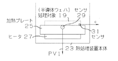
熱処理装置17は、例えば半導体製造装置(図示せず。)の一部をなし、例えば図2に示すように、熱処理装置本体23と、この内部に適当な支持手段(図示せず)によって支持された加熱プレート25と、この加熱プレート25の下面に配置され交流電力などで駆動されるヒータ27と、その加熱プレート25内部にあって上表面近傍に埋設され加熱プレート表面温度である測定値PV1を出力する温度測定用センサ29を有して形成されている。
The
なお、操作量演算部15は、図6のような出力部13などを介して熱処理装置17のヒータ27に接続され、ヒータ27に印加される交流電力を切換えるようになっているが、便宜上、図1では出力部の図示を省略する。
The manipulated
熱処理装置17は、処理対象19としての例えば半導体ウェハ(図2中破線で示す。)が加熱プレート25の所定の処理位置に載置されたとき、構造変化信号cを出力する位置検出用センサ31を有している。
The
熱処理装置17は、センサ29を操作量演算部15、処理対象19、いずれも後述するシステム同定部33、推定演算部21および処理状態検出部35に接続している。
The
図1において、処理対象19は、後述するように予め熱処理されるものであり、事前の熱処理過程で得られた処理対象19の表面温度測定値(第2の制御量:単に測定値とする。)PV2を出力するもので、システム同定部33に接続されている。
In FIG. 1, a processing object 19 is preliminarily heat-treated as described later, and a surface temperature measurement value (second control amount: simply a measurement value) of the processing object 19 obtained in a prior heat treatment process. ) Outputs PV2, and is connected to the
予め熱処理される処理対象19から測定値PV2を出力するセンサは、図2中の処理対象19の表面に適当に配置されるが、図示は省略されている。 A sensor that outputs the measurement value PV2 from the processing target 19 that is preheated is appropriately arranged on the surface of the processing target 19 in FIG.
システム同定部33は、熱処理装置17からの測定値PV1と、処理対象19からの測定値PV2を受けてシステム同定を行い、その後、実際に熱処理する処理対象19の温度推定に用いる推定パラメータa、bを算出するもので、推定演算部21に接続されている。
The
システム同定部33は、事前に、熱処理装置17からの測定値PV1と、これを処理対象19に入力したとき(加えたとき)の処理対象19からの測定値PV2を取り込み、これら測定値PV1、PV2を例えば最小二乗法によって数値演算して加熱プレート25から処理対象19への熱移動特性を得るものである。
The
換言すれば、システム同定部33は、その測定値PV1をシステムへの入力値、測定値PV2をシステムからの出力値としたときの熱処理装置17および処理対象19で形成される当該システムを同定し、処理対象19の温度推定値を得る演算に用いられる推定パラメータa、bを導出する数式モデルとして所定の微分方程式を最小二乗法によって求める機能を有し、それら推定パラメータa、bを出力するものである。
In other words, the
最小二乗法による同定は、そのプロセス制御系を1次遅れ系又は高次遅れ系などの数式モデルに近似する微分方程式を用い、所定のタイミングで測定値PV1と測定値PV2を取り込み、その微分方程式の係数を複数のそれらの測定値PV1、PV2の値を用いて算出し、数式モデルを形成するものである。 For identification by the least square method, a differential equation that approximates the process control system to a mathematical model such as a first-order lag system or a higher-order lag system is used, and the measured value PV1 and the measured value PV2 are fetched at a predetermined timing. Is calculated using the values of the plurality of measured values PV1 and PV2 to form a mathematical model.
数式モデルは、例えば次の数1で表現される。
The mathematical model is expressed by the

これを初期値をゼロ「0」としてラプラス変換すると、次の数2の伝達関数となる。 When this is Laplace transformed with an initial value of zero “0”, the following transfer function of Equation 2 is obtained.
ここで、符号a、bは推定パラメータ、符号tは測定時間、符号uは入力、符号yは出力、符号sはラプラス演算子、符号n、mは微分方程式の階数(伝達関数の次数)である(以下同じ。)。 Here, the symbols a and b are estimation parameters, the symbol t is a measurement time, the symbol u is an input, the symbol y is an output, the symbol s is a Laplace operator, the symbols n and m are the ranks of the differential equation (the order of the transfer function). Yes (the same shall apply hereinafter).
システム同定部33は、この数1に対して測定値PV1、PV2を代入し、最小二乗法によって推定パラメータa、bを求め、推定演算部21へ出力する。
The
処理状態検出部35は、例えば熱処理装置17において、処理対象19が加熱プレート25の所定の処理位置に載置され、処理対象19の熱処理が可能であるか否かを検出するもので、熱処理可能状態であるとき検出信号Cを出力するもので、推定演算部21および初期値設定部37に接続されている。
For example, in the
処理状態検出部35は、熱処理装置17の加熱プレート25に配置したセンサ31からの構造変化信号cが入力されたとき、そのまま検出信号Cとして出力する機能を有している。
The processing
さらに、処理状態検出部35は、常温の処理対象19が所定の位置に配置されると、加熱プレート25のセンサ29からの測定値PV1が大きく低下するから、熱処理装置17からの測定値PV1の変化を検出し、単位時間当たりの変化量が所定の変化量を超えたとき、検出信号Cを出力するよう形成可能である。
Further, the processing
また、図示しない検出手段によって処理対象19が所定の位置に配置されたとき、検出信号Cを出力するよう処理状態検出部35を形成可能である。
In addition, the processing
初期値設定部37は、推定演算部21において推定値を推定演算するために用いる推定初期値が処理対象19に応じて予め設定されており、検出信号Cが入力されたとき、その推定初期値を推定演算部21へ出力する機能を有している。
In the initial
なお、推定初期値は、上述した数1において測定時間tを「0」としたときの出力y(0)の値であり、経験則から室温(常温)程度の値である。
Note that the estimated initial value is the value of the output y (0) when the measurement time t is set to “0” in
推定演算部21は、システム同定部33から推定パラメータa、bを受けると、所定の推定演算式を設定する一方、処理状態検出部35からの検出信号Cを受けたとき、熱処理装置17からの測定値PV1、初期値設定部37からの推定初期値に基づき、その推定演算式を解いて処理対象19の温度推定値を演算するもので、操作量演算部15および図示しないディスプレイなどに接続されている。
When the
推定演算式を解く手順を簡単に示せば、以下のようになる。 A simple procedure for solving the estimation formula is as follows.
すなわち、処理対象19のモデルはこれを1次遅れとすると、以下のような伝達関数の数3で記述できる。 That is, the model of the processing target 19 can be described by the following transfer function number 3 assuming that this is a first-order lag.
数3は上述した推定演算式である次の数4に展開できる。 Equation 3 can be expanded into the following equation 4 which is the above-described estimation calculation formula.
符号(ハット)yは推定値であり、方程式で示せば上述した推定演算式である次の数5になる。 The sign (hat) y is an estimated value, and if expressed by an equation, the following equation (5) which is the above-described estimation arithmetic expression is obtained.
この方程式(数5)は逐次推定を示すので、この方程式を解くには1測定タイミング前の推定値が必要となり、初期状態では推定初期値としての(ハット)yが必要であり、上述した初期値設定部37から得られる。
Since this equation (Equation 5) indicates sequential estimation, an estimated value before one measurement timing is required to solve this equation, and (hat) y as an estimated initial value is required in the initial state. Obtained from the
上述した操作量演算部15においては、測定値PV1と目標値SVとの偏差に基づくPID演算結果に対して、推定値と測定値PV1の差に所定の倍率を乗じた値を加算して操作量MVを演算して熱処理装置側に直接又は間接的に出力する。
In the operation
そして、それらシステム同定部33、推定演算部21、処理状態検出部35および初期値設定部37によって本発明に係る温度推定装置Aが構成されており、操作量演算部15を含めて本発明に係る制御装置Bが構成されている。
And the temperature estimation apparatus A which concerns on this invention is comprised by these
次に、上述した本発明に係る制御装置の使用例および動作を簡単に説明する。 Next, a usage example and operation of the control device according to the present invention will be briefly described.
まず、熱処理する予定の処理対象19を熱処理装置17の加熱プレート25に載置し、処理対象19の所望の温度測定箇所に図示しないセンサを配置し、実際に熱処理する手順で処理対象19を操作量演算部15で加熱制御する。
First, the processing target 19 to be heat-treated is placed on the
なお、上述した推定演算部21では推定演算が行われず、推定値が出力されないようになっている。
Note that the
この場合、操作量演算部15は、目標値SVと熱処理装置17からの測定値PV1との偏差から、この偏差が小さくなるよう操作量MVをPID演算して熱処理装置17に出力する。
In this case, the manipulated
熱処理装置17は、その操作量MVに基づきヒータ27を加熱制御して加熱プレート25を加熱し、所定のタイミングで加熱プレート25の上表面近傍の測定値PV1を操作量演算部15、システム同定部33、推定演算部21および処理状態検出部35へ出力する。
The
熱処理装置17で加熱された処理対象19からは、同じ所定のタイミングで処理対象19自体の測定値PV2がシステム同定部33へ入力される。
From the processing object 19 heated by the
システム同定部33では、熱処理装置17からの測定値PV1と、処理対象19からの測定値PV2を受け、測定値PV2の得られるシステム同定を行い、微分方程式を立てるとともに最小二乗法により、実際に熱処理する処理対象19の温度推定に用いる推定パラメータa、bを推定演算部21へ出力する。
The
そのため、推定演算部21には、システム同定部33からの推定パラメータa、bに基づき、処理対象19の温度推定値を演算する推定演算式が設定される。
Therefore, an estimation calculation expression for calculating the estimated temperature value of the processing target 19 is set in the
図3は、処理対象19を熱処理装置17の加熱プレート25に載置してから所定のタイミング毎にセンサ29から得られた加熱プレート25の表面温度を仮想的に結んで推移させた特性図であり、図4はその加熱プレート25に載置した処理対象19から所定のタイミング毎に得られた処理対象温度を仮想的に結んで推移させた特性図である。
FIG. 3 is a characteristic diagram in which the surface temperature of the
次に、実際に処理対象19を熱処理する場合を説明する。 Next, a case where the processing target 19 is actually heat-treated will be described.
処理対象19が熱処理装置17の加熱プレート25に載置された状態では、熱処理装置17から構造変化信号cが処理状態検出部35へ出力されるから、処理状態検出部35から検出信号Cが推定演算部21および初期値設定部37へ出力されている。
In a state where the processing object 19 is placed on the
この状態で、操作量演算部15からの操作量MVによって熱処理装置17が加熱制御され、処理対象19が測定値PV1によって加熱される。
In this state, the
推定演算部21では、熱処理装置17からの測定値PV1を所定のタイミングで取り込み、これと推定初期値とを上述した推定演算式に代入して推定演算式を解き、処理対象19の推定値を演算して操作量演算部15へ出力する。
The
操作量演算部15では、温度推定値と測定値PV1の差を算出した結果に所定の倍率を乗じた結果をPID演算結果に加算して操作量MVとして処理装置17へ出力し、この修正された操作量MVによって熱処理装置17を介して処理対象19が熱処理される。
The manipulated
図5は、処理対象19の推定温度の変移(破線)と処理対象19の実際の温度変移(実線)を示す特性図である。 FIG. 5 is a characteristic diagram showing a change in the estimated temperature of the processing target 19 (broken line) and an actual temperature shift of the processing target 19 (solid line).
このように、本発明の制御装置Bでは、操作量演算部15が、熱処理される処理対象19に加えられる測定値PV1を目標値SVに近づけるような操作量MVを演算して熱処理装置17に出力し、システム同定部33が、その熱処理装置17からその処理対象19に加えられる測定値PV1と、予めこの測定値PV1が加えられて処理対象19から得られる測定値PV2との関係に基づき熱処理装置17および処理対象19のシステム同定をしてその測定値PV2が得られるような推定パラメータを導出し、処理状態検出部35がその処理対象19が熱処理される状態であることを検出したとき検出信号Cを出力し、推定演算部21が、その検出信号Cを受けて、初期値設定部37からの推定初期値、推定パラメータおよび測定値PV1に基づきその処理対象19の温度を推定演算し、上記操作量演算部15が、その推定値を目標値SVに近づけるようにその操作量MVを演算する構成となっているから、処理対象19に直接的にセンサを配置しなくとも、処理対象19を熱処理する測定値PV1から処理対象19自体の温度を正確に推定可能となり、実際のプラント制御系に応じてより適切、正確な温度制御が可能となる。
As described above, in the control device B of the present invention, the manipulated
また、そのような、システム同定部33、推定演算部21、処理状態検出部35、初期値設定部37を有して制御装置Bに用いる温度推定装置Aを構成すると、処理対象に直接的にセンサを配置しなくとも、処理対象19を熱処理する測定値PV1から処理対象19自体の温度をより適切、正確に推定可能となる。
In addition, when the temperature estimation device A used for the control device B having the
しかも、システム同定部33が、微分方程式を基にした推定モデルに基づいて推定パラメータを導出するよう形成したから、種々の構成の処理対象19に合わせた複数の微分方程式を立てることが容易であり、種々の複雑な処理対象19についても正確な温度推定が可能となる。
Moreover, since the
上述した本発明において、操作量演算部15では、熱処理装置17からの測定値PV1に代えて、処理対象19の推定値を測定値PV1として目標値SVとの偏差からPID演算して操作量MVを出力するよう形成することも可能である。
In the above-described present invention, the manipulated
さらに、本発明において、システム同定部33で推定パラメータa、bを求める手法としては、最小二乗法の他に微分方程式からカルマンフィルタ法や最尤推定法などを用いることも可能であるし、その微分方程式もこれ以外に伝達関数モデルや状態空間モデルを用いてシステム同定して推定パラメータa、bを求めることも可能である。
Further, in the present invention, as a method for obtaining the estimation parameters a and b by the
上述した実施の形態では加熱処理について説明したが、冷却処理など熱処理一般に実施可能である。 Although the heat treatment has been described in the above-described embodiment, heat treatment such as cooling treatment can be generally performed.
1、23 熱処理装置本体
3、25 加熱プレート
5、27 ヒータ
7、19、31 処理対象(半導体ウェハ)
9、29、31 センサ
11、15 操作量演算部
13 出力部
17 熱処理装置
21 推定演算部
33 システム同定部
35 処理状態検出部
37 初期値設定部
A 温度推定装置
B 制御装置
1, 23 Heat
9, 29, 31
Claims (3)
前記処理対象が熱処理される状態であることを検出したとき、当該熱処理可能状態を示す検出信号を出力する処理状態検出部と、
前記検出信号を受けて初期値、前記推定パラメータおよび前記第1の制御量に基づき、前記処理対象の温度を推定演算する推定演算部と、
前記推定演算のための前記処理対象に係る初期値が予め設定され、前記検出信号を受けて前記初期値を前記推定演算部に出力する初期値設定部と、
とを具備することを特徴とする温度推定装置。 Based on the first control amount based on the relationship between the first control amount applied to the processing target to be heat-treated and the second control amount obtained from the processing target by adding the first control amount in advance. A system identification unit for deriving an estimation parameter used for calculation of the first control amount so that the second control amount can be obtained by identifying a system from which the second control amount is obtained;
When it is detected that the processing target is in a state to be heat-treated, a processing state detection unit that outputs a detection signal indicating the heat-treatable state; and
Receiving the detection signal, based on an initial value, the estimation parameter, and the first control amount, an estimation calculation unit that estimates and calculates the temperature of the processing target;
An initial value for the estimation calculation is set in advance, and an initial value setting unit that receives the detection signal and outputs the initial value to the estimation calculation unit;
The temperature estimation apparatus characterized by comprising.
前記熱処理部から前記処理対象に加えられる前記第1の制御量と、予めこの第1の制御量が加えられて前記処理対象から得られる第2の制御量との関係から、前記第1の制御量に基づき前記第2の制御量の得られるシステムを同定して前記第2の制御量が得られるような前記第1の制御量の演算に用いられる推定パラメータを導出するシステム同定部と、
前記処理対象が熱処理される状態であることを検出したとき、当該熱処理可能状態を示す検出信号を出力する処理状態検出部と、
前記検出信号を受けて初期値、前記推定パラメータおよび前記第1の制御量に基づき、前記処理対象の温度を推定演算する推定演算部と、
前記推定演算のための前記処理対象に係る初期値が予め設定され、前記検出信号を受けて前記初期値を前記推定演算部に出力する初期値設定部と、
を具備する制御装置であり、
前記操作量演算部は、前記推定演算部からの推定値を前記目標値に近づけるように前記操作量を演算して前記熱処理部側に出力するものであることを特徴とする制御装置。 An operation amount calculation unit that calculates an operation amount that brings the first control amount applied to the target to be heat-treated closer to the target value and outputs the operation amount to the heat treatment unit side;
From the relationship between the first control amount applied to the processing target from the heat treatment unit and the second control amount obtained from the processing target by adding the first control amount in advance, the first control amount A system identification unit for deriving an estimation parameter used for calculating the first control amount so that the second control amount can be obtained by identifying a system that obtains the second control amount based on a quantity;
When it is detected that the processing target is in a state to be heat treated, a processing state detection unit that outputs a detection signal indicating the heat treatment possible state; and
Receiving the detection signal, based on an initial value, the estimation parameter, and the first control amount, an estimation calculation unit that estimates and calculates the temperature of the processing target;
An initial value for the estimation calculation is set in advance, and an initial value setting unit that receives the detection signal and outputs the initial value to the estimation calculation unit;
A control device comprising:
The control device characterized in that the manipulated variable calculator calculates the manipulated variable so that an estimated value from the estimated calculator is close to the target value and outputs the manipulated variable to the heat treatment unit.
Priority Applications (1)
| Application Number | Priority Date | Filing Date | Title |
|---|---|---|---|
| JP2004283836A JP2006099352A (en) | 2004-09-29 | 2004-09-29 | Temperature estimation device and controller unit using the same |
Applications Claiming Priority (1)
| Application Number | Priority Date | Filing Date | Title |
|---|---|---|---|
| JP2004283836A JP2006099352A (en) | 2004-09-29 | 2004-09-29 | Temperature estimation device and controller unit using the same |
Publications (1)
| Publication Number | Publication Date |
|---|---|
| JP2006099352A true JP2006099352A (en) | 2006-04-13 |
Family
ID=36239111
Family Applications (1)
| Application Number | Title | Priority Date | Filing Date |
|---|---|---|---|
| JP2004283836A Pending JP2006099352A (en) | 2004-09-29 | 2004-09-29 | Temperature estimation device and controller unit using the same |
Country Status (1)
| Country | Link |
|---|---|
| JP (1) | JP2006099352A (en) |
Cited By (5)
| Publication number | Priority date | Publication date | Assignee | Title |
|---|---|---|---|---|
| JP2008249641A (en) * | 2007-03-30 | 2008-10-16 | Mitsui Eng & Shipbuild Co Ltd | Temperature estimating method and temperature estimating device |
| JP2009198298A (en) * | 2008-02-21 | 2009-09-03 | Yamatake Corp | Temperature estimation method and apparatus |
| CN102754297A (en) * | 2010-03-24 | 2012-10-24 | 理化工业株式会社 | Multichannel power controller |
| WO2013125118A1 (en) * | 2012-02-22 | 2013-08-29 | カルソニックカンセイ株式会社 | Parameter estimation device |
| JPWO2017126015A1 (en) * | 2016-01-18 | 2018-05-10 | 三菱電機株式会社 | Measuring apparatus and measuring method |
Citations (5)
| Publication number | Priority date | Publication date | Assignee | Title |
|---|---|---|---|---|
| JPH06192840A (en) * | 1992-12-25 | 1994-07-12 | Dainippon Screen Mfg Co Ltd | Heat treatment device for semiconductor wafer |
| JP2000235944A (en) * | 1999-02-16 | 2000-08-29 | Komatsu Ltd | Substrate temperature estimating apparatus and its method and substrate temperature controller using the same |
| JP2000277237A (en) * | 1999-03-24 | 2000-10-06 | Komatsu Ltd | Base board temperature control plate and controlling device fitted with the same |
| JP2002091574A (en) * | 2000-09-13 | 2002-03-29 | Tokyo Electron Ltd | Batch type heat treatment equipment and its control method |
| JP2004206515A (en) * | 2002-12-26 | 2004-07-22 | Rkc Instrument Inc | Controller |
-
2004
- 2004-09-29 JP JP2004283836A patent/JP2006099352A/en active Pending
Patent Citations (5)
| Publication number | Priority date | Publication date | Assignee | Title |
|---|---|---|---|---|
| JPH06192840A (en) * | 1992-12-25 | 1994-07-12 | Dainippon Screen Mfg Co Ltd | Heat treatment device for semiconductor wafer |
| JP2000235944A (en) * | 1999-02-16 | 2000-08-29 | Komatsu Ltd | Substrate temperature estimating apparatus and its method and substrate temperature controller using the same |
| JP2000277237A (en) * | 1999-03-24 | 2000-10-06 | Komatsu Ltd | Base board temperature control plate and controlling device fitted with the same |
| JP2002091574A (en) * | 2000-09-13 | 2002-03-29 | Tokyo Electron Ltd | Batch type heat treatment equipment and its control method |
| JP2004206515A (en) * | 2002-12-26 | 2004-07-22 | Rkc Instrument Inc | Controller |
Cited By (8)
| Publication number | Priority date | Publication date | Assignee | Title |
|---|---|---|---|---|
| JP2008249641A (en) * | 2007-03-30 | 2008-10-16 | Mitsui Eng & Shipbuild Co Ltd | Temperature estimating method and temperature estimating device |
| JP2009198298A (en) * | 2008-02-21 | 2009-09-03 | Yamatake Corp | Temperature estimation method and apparatus |
| CN102754297A (en) * | 2010-03-24 | 2012-10-24 | 理化工业株式会社 | Multichannel power controller |
| WO2013125118A1 (en) * | 2012-02-22 | 2013-08-29 | カルソニックカンセイ株式会社 | Parameter estimation device |
| JP5319854B1 (en) * | 2012-02-22 | 2013-10-16 | カルソニックカンセイ株式会社 | Parameter estimation device |
| JPWO2017126015A1 (en) * | 2016-01-18 | 2018-05-10 | 三菱電機株式会社 | Measuring apparatus and measuring method |
| KR20180082534A (en) * | 2016-01-18 | 2018-07-18 | 미쓰비시덴키 가부시키가이샤 | Measuring devices and measuring methods |
| KR102085042B1 (en) * | 2016-01-18 | 2020-03-05 | 미쓰비시덴키 가부시키가이샤 | Measuring device and measuring method |
Similar Documents
| Publication | Publication Date | Title |
|---|---|---|
| KR100707097B1 (en) | Temperature Control Method and Temperature Controller | |
| JP4978001B2 (en) | Temperature control method, temperature control apparatus, and heat treatment apparatus | |
| KR101086128B1 (en) | Control apparatus and power estimating method | |
| KR101420920B1 (en) | Control apparatus and control method | |
| US6711531B1 (en) | Temperature control simulation method and apparatus | |
| WO2007083498A1 (en) | Temperature estimation method and device | |
| US11032938B2 (en) | Temperature control device and control method thereof | |
| JP6859725B2 (en) | PID controller, PID control method, and PID control program | |
| JP5272669B2 (en) | Plant control system and control method | |
| KR100791199B1 (en) | Distance Estimating Apparatus, Abnormal Detecting Apparatus, Temperature Regulator and Heat Treatment Apparatus | |
| CN111665882B (en) | Temperature control method and system | |
| JP2006099352A (en) | Temperature estimation device and controller unit using the same | |
| JP2017026522A5 (en) | ||
| CN107798161A (en) | Design evaluatio accessory system | |
| KR101582675B1 (en) | temperature control apparatus of heating and cooling mold using extended kalman filter | |
| US20150019596A1 (en) | Controller and data collecting method | |
| US20040148059A1 (en) | Limit cycle autotuning method and heat/cool control apparatus | |
| TWI697749B (en) | heating equipment | |
| JP2010218007A (en) | Disturbance estimation device, control object model estimation device, feedforward amount estimation device, and controller | |
| JP2008299697A (en) | Control method, temperature control method, correction device, temperature adjuster, and program | |
| JP6087262B2 (en) | Numerical controller | |
| US8150558B2 (en) | Temperature control method and temperature controller | |
| JP5264468B2 (en) | Control apparatus and control method | |
| KR101582676B1 (en) | temperature control apparatus of heating and cooling mold using extended kalman filter | |
| JP2024086226A (en) | Heating furnace simulation system |
Legal Events
| Date | Code | Title | Description |
|---|---|---|---|
| A621 | Written request for application examination |
Free format text: JAPANESE INTERMEDIATE CODE: A621 Effective date: 20070404 |
|
| A977 | Report on retrieval |
Free format text: JAPANESE INTERMEDIATE CODE: A971007 Effective date: 20091125 |
|
| A131 | Notification of reasons for refusal |
Free format text: JAPANESE INTERMEDIATE CODE: A131 Effective date: 20091208 |
|
| A521 | Written amendment |
Free format text: JAPANESE INTERMEDIATE CODE: A523 Effective date: 20100204 |
|
| A131 | Notification of reasons for refusal |
Free format text: JAPANESE INTERMEDIATE CODE: A131 Effective date: 20101109 |
|
| A02 | Decision of refusal |
Free format text: JAPANESE INTERMEDIATE CODE: A02 Effective date: 20110302 |