JP2006075257A - Chair - Google Patents
Chair Download PDFInfo
- Publication number
- JP2006075257A JP2006075257A JP2004260510A JP2004260510A JP2006075257A JP 2006075257 A JP2006075257 A JP 2006075257A JP 2004260510 A JP2004260510 A JP 2004260510A JP 2004260510 A JP2004260510 A JP 2004260510A JP 2006075257 A JP2006075257 A JP 2006075257A
- Authority
- JP
- Japan
- Prior art keywords
- lumbar
- support
- pelvis
- chair
- support portion
- Prior art date
- Legal status (The legal status is an assumption and is not a legal conclusion. Google has not performed a legal analysis and makes no representation as to the accuracy of the status listed.)
- Granted
Links
- 210000004197 pelvis Anatomy 0.000 claims abstract description 136
- 210000000689 upper leg Anatomy 0.000 claims abstract description 27
- 210000001217 buttock Anatomy 0.000 claims abstract description 13
- 230000004224 protection Effects 0.000 claims description 41
- 230000033001 locomotion Effects 0.000 claims description 33
- 210000002414 leg Anatomy 0.000 claims description 30
- 210000001624 hip Anatomy 0.000 claims description 27
- 230000001105 regulatory effect Effects 0.000 claims description 17
- 230000001681 protective effect Effects 0.000 claims description 14
- 230000002829 reductive effect Effects 0.000 claims description 7
- 210000003127 knee Anatomy 0.000 claims description 4
- 210000004705 lumbosacral region Anatomy 0.000 claims description 4
- 230000001276 controlling effect Effects 0.000 claims description 3
- 208000008035 Back Pain Diseases 0.000 abstract description 6
- 208000037265 diseases, disorders, signs and symptoms Diseases 0.000 abstract description 4
- 230000003387 muscular Effects 0.000 abstract description 3
- 208000035475 disorder Diseases 0.000 abstract 2
- 230000007423 decrease Effects 0.000 abstract 1
- 210000004013 groin Anatomy 0.000 abstract 1
- 210000000038 chest Anatomy 0.000 description 86
- 230000036544 posture Effects 0.000 description 57
- 238000010586 diagram Methods 0.000 description 38
- 230000007246 mechanism Effects 0.000 description 31
- 238000004804 winding Methods 0.000 description 21
- 238000005452 bending Methods 0.000 description 12
- 230000037237 body shape Effects 0.000 description 11
- 230000008602 contraction Effects 0.000 description 11
- 210000003205 muscle Anatomy 0.000 description 9
- 208000027418 Wounds and injury Diseases 0.000 description 8
- 230000008859 change Effects 0.000 description 8
- 239000000463 material Substances 0.000 description 8
- 230000006866 deterioration Effects 0.000 description 7
- 230000006870 function Effects 0.000 description 7
- JOYRKODLDBILNP-UHFFFAOYSA-N Ethyl urethane Chemical compound CCOC(N)=O JOYRKODLDBILNP-UHFFFAOYSA-N 0.000 description 6
- 210000000115 thoracic cavity Anatomy 0.000 description 6
- 230000007704 transition Effects 0.000 description 6
- 210000000078 claw Anatomy 0.000 description 5
- 230000000694 effects Effects 0.000 description 5
- 206010049565 Muscle fatigue Diseases 0.000 description 4
- 238000013459 approach Methods 0.000 description 4
- 238000006243 chemical reaction Methods 0.000 description 3
- 239000003814 drug Substances 0.000 description 3
- 239000006260 foam Substances 0.000 description 3
- 239000007788 liquid Substances 0.000 description 3
- 230000007774 longterm Effects 0.000 description 3
- 230000002265 prevention Effects 0.000 description 3
- 230000003449 preventive effect Effects 0.000 description 3
- 239000000758 substrate Substances 0.000 description 3
- KAKZBPTYRLMSJV-UHFFFAOYSA-N Butadiene Chemical compound C=CC=C KAKZBPTYRLMSJV-UHFFFAOYSA-N 0.000 description 2
- RRHGJUQNOFWUDK-UHFFFAOYSA-N Isoprene Chemical compound CC(=C)C=C RRHGJUQNOFWUDK-UHFFFAOYSA-N 0.000 description 2
- 208000028389 Nerve injury Diseases 0.000 description 2
- 230000002159 abnormal effect Effects 0.000 description 2
- 230000001133 acceleration Effects 0.000 description 2
- 230000002411 adverse Effects 0.000 description 2
- 210000000988 bone and bone Anatomy 0.000 description 2
- 210000003679 cervix uteri Anatomy 0.000 description 2
- 210000003792 cranial nerve Anatomy 0.000 description 2
- 238000013500 data storage Methods 0.000 description 2
- 201000010099 disease Diseases 0.000 description 2
- 229920001971 elastomer Polymers 0.000 description 2
- 238000007667 floating Methods 0.000 description 2
- 239000012530 fluid Substances 0.000 description 2
- 230000002650 habitual effect Effects 0.000 description 2
- 239000012948 isocyanate Substances 0.000 description 2
- 150000002513 isocyanates Chemical class 0.000 description 2
- 235000013372 meat Nutrition 0.000 description 2
- 230000003340 mental effect Effects 0.000 description 2
- 239000002184 metal Substances 0.000 description 2
- 238000000034 method Methods 0.000 description 2
- 230000008764 nerve damage Effects 0.000 description 2
- 230000036961 partial effect Effects 0.000 description 2
- 229920005862 polyol Polymers 0.000 description 2
- 150000003077 polyols Chemical class 0.000 description 2
- 230000009467 reduction Effects 0.000 description 2
- 229920005989 resin Polymers 0.000 description 2
- 239000011347 resin Substances 0.000 description 2
- 230000002441 reversible effect Effects 0.000 description 2
- 239000005060 rubber Substances 0.000 description 2
- 210000001519 tissue Anatomy 0.000 description 2
- 210000003371 toe Anatomy 0.000 description 2
- XLYOFNOQVPJJNP-UHFFFAOYSA-N water Substances O XLYOFNOQVPJJNP-UHFFFAOYSA-N 0.000 description 2
- 206010061218 Inflammation Diseases 0.000 description 1
- 125000002066 L-histidyl group Chemical group [H]N1C([H])=NC(C([H])([H])[C@](C(=O)[*])([H])N([H])[H])=C1[H] 0.000 description 1
- 208000008930 Low Back Pain Diseases 0.000 description 1
- 208000002193 Pain Diseases 0.000 description 1
- 241000270295 Serpentes Species 0.000 description 1
- 229910000639 Spring steel Inorganic materials 0.000 description 1
- 210000001015 abdomen Anatomy 0.000 description 1
- 230000009471 action Effects 0.000 description 1
- 230000017531 blood circulation Effects 0.000 description 1
- 244000309466 calf Species 0.000 description 1
- 230000004087 circulation Effects 0.000 description 1
- 239000002131 composite material Substances 0.000 description 1
- 230000006835 compression Effects 0.000 description 1
- 238000007906 compression Methods 0.000 description 1
- 239000012141 concentrate Substances 0.000 description 1
- 230000006378 damage Effects 0.000 description 1
- 230000006806 disease prevention Effects 0.000 description 1
- 230000009429 distress Effects 0.000 description 1
- 230000008030 elimination Effects 0.000 description 1
- 238000003379 elimination reaction Methods 0.000 description 1
- 238000005187 foaming Methods 0.000 description 1
- 230000009760 functional impairment Effects 0.000 description 1
- 239000011521 glass Substances 0.000 description 1
- 230000009477 glass transition Effects 0.000 description 1
- 230000005484 gravity Effects 0.000 description 1
- 210000001621 ilium bone Anatomy 0.000 description 1
- 230000006872 improvement Effects 0.000 description 1
- 230000004054 inflammatory process Effects 0.000 description 1
- 210000001503 joint Anatomy 0.000 description 1
- 210000000281 joint capsule Anatomy 0.000 description 1
- 210000003041 ligament Anatomy 0.000 description 1
- 239000012528 membrane Substances 0.000 description 1
- 230000004048 modification Effects 0.000 description 1
- 238000012986 modification Methods 0.000 description 1
- 238000000465 moulding Methods 0.000 description 1
- 210000005036 nerve Anatomy 0.000 description 1
- 208000015122 neurodegenerative disease Diseases 0.000 description 1
- 210000000103 occipital bone Anatomy 0.000 description 1
- 230000035479 physiological effects, processes and functions Effects 0.000 description 1
- 229920001225 polyester resin Polymers 0.000 description 1
- 238000006116 polymerization reaction Methods 0.000 description 1
- 229920005672 polyolefin resin Polymers 0.000 description 1
- 230000001144 postural effect Effects 0.000 description 1
- 238000003825 pressing Methods 0.000 description 1
- 230000008707 rearrangement Effects 0.000 description 1
- 210000000323 shoulder joint Anatomy 0.000 description 1
- 210000003625 skull Anatomy 0.000 description 1
- 230000035882 stress Effects 0.000 description 1
- 230000008961 swelling Effects 0.000 description 1
- 210000000331 sympathetic ganglia Anatomy 0.000 description 1
- 229920003051 synthetic elastomer Polymers 0.000 description 1
- 239000005061 synthetic rubber Substances 0.000 description 1
- 238000002560 therapeutic procedure Methods 0.000 description 1
- 230000009466 transformation Effects 0.000 description 1
- 239000013585 weight reducing agent Substances 0.000 description 1
- 238000003079 width control Methods 0.000 description 1
Images


Landscapes
- Chair Legs, Seat Parts, And Backrests (AREA)
- Chairs For Special Purposes, Such As Reclining Chairs (AREA)
Abstract
Description
本発明は椅子やカーシートに関する。 The present invention relates to a chair and a car seat.
従来の椅子やカーシートは座ったときに体重がかかる背もたれと座面の一部の領域で体重を支える方法であり、背もたれのリクライニング機能により前傾や後傾を可能としている。リクライニング機能としては、水平な座面の側面に操作スイッチがあり、背もたれが前後に倒れることにより姿勢に合わせる方法を取っているものなどがある(例えば、特許文献1参照。)。 Conventional chairs and car seats are a method of supporting the weight on a backrest that takes weight when sitting and a partial area of the seating surface, and the reclining function of the backrest enables forward tilt and backward tilt. As the reclining function, there is an operation switch on the side surface of a horizontal seating surface, and a method of adjusting the posture by tilting the backrest back and forth (see, for example, Patent Document 1).
しかし、従来の椅子やカーシートは背もたれと座面のうち体重のかかる一部の領域により体重を支えるため、背もたれと腰の間や座面の上部にすき間ができやすい。特に、前傾時は背もたれ上部に、後傾時は背もたれと腰の間にできるすき間が徐々に広がる傾向にある。 However, since conventional chairs and car seats support weight by a part of the backrest and seating surface that is heavy, it is easy to create a gap between the backrest and the waist or at the top of the seating surface. In particular, the gap formed between the backrest and the waist tends to gradually widen at the upper part of the backrest when tilting forward and when it is tilted backward.
そのため椅子より受ける体圧が分散せず、局部的に体圧が集中して身体に異常な力が作用し好ましくない。又、椅子に座り続けると次第に臀部が前方にずれ、腰部は後傾で頭頸部は猫背前屈みの姿勢となる。姿勢が悪化すると同時に首、肩、腰を含めた背筋が緊張し疲れる。更に、そのような座位を長期間続けると悪い姿勢が習慣化され、筋肉のみならず脊椎やその他骨格にまで悪影響を与える。 Therefore, the body pressure received from the chair does not disperse, the body pressure concentrates locally, and abnormal force acts on the body, which is not preferable. Also, if you continue to sit on the chair, the buttocks will gradually shift forward, the waist will tilt backwards, and the head and neck will bend forward. At the same time the posture worsens, the back muscles including the neck, shoulders and waist become tense and tired. Furthermore, if such a sitting position is continued for a long period of time, a bad posture becomes habitual and adversely affects not only muscles but also the spine and other skeletons.
そもそも従来の座面は平坦で、尾骨や坐骨結節など重心のかかる一部によってのみ体重を支える形状となっており、腸骨や仙骨などを含む骨盤〜臀部を形成する骨格や筋肉全体で体圧分散させ体重を支える構造になっていない。上述のリクライニング機構においても従来の椅子やカーシートは背もたれの下端と座面後端が交差する位置に背もたれと座面とが軸着して背もたれが傾斜する軸心がある。このため本来頸椎や腰椎のように前後屈が不可能な骨盤〜臀部は前方や後方にずれることにより背もたれと腰の間にすき間をつくりながら角度を変えて対応せざるを得ない。 In the first place, the conventional seating surface is flat and has a shape that supports the weight only by the part of the center of gravity such as the coccyx and sciatic nodules, and the body pressure in the skeleton and muscles that form the pelvis to buttock including the iliac and sacrum It is not structured to disperse and support weight. Also in the above reclining mechanism, a conventional chair or car seat has an axial center where the backrest and the seating surface are attached to each other at a position where the lower end of the backrest and the rear end of the seating surface intersect and the backrest is inclined. For this reason, the pelvis to the hip that cannot be bent back and forth like the cervical vertebra and the lumbar vertebra must be changed by changing the angle while creating a gap between the backrest and the waist by shifting forward and backward.
即ち、従来の椅子は、着座する人に合わせるのではなく、着座した人が椅子の形状に合わせて無理な姿勢をとらざるを得ないような構成であった。 That is, the conventional chair is not adapted to the seated person, but has a configuration in which the seated person has to take an unreasonable posture according to the shape of the chair.
この人間工学的に不合理なリクライニングシステムが腰や背中に負担をかけ姿勢悪化や脊椎の生理的湾曲の増悪を招く。これら人間工学における問題点を解決し、長時間座っていても筋・肉が緊張せず疲れない、また、座ることにより正しい姿勢と脊椎の生理的湾曲が保てる必要がある。 This ergonomically unreasonable reclining system puts strain on the lower back and back, leading to worse posture and worsening of the spinal physiology. It is necessary to solve these problems in ergonomics so that even if sitting for a long time, muscles and flesh do not become tense and tired, and it is necessary to maintain the correct posture and physiological curvature of the spine by sitting.
椅子やカーシートはわれわれ現代人が仕事をするうえで、また生活していくうえで今や必須のアイテムである。多くの現代人が数時間から十数時間のあいだ椅子やカーシートの上で過ごしている。わたしたちの人生の何割かは椅子やカーシートでの生活なのである。それら生活の一部である椅子やカーシートを人間工学的に改良することにより、わたしたち現代人の生活はもっと健康的かつ安全で快適なものとなる。 Chairs and car seats are now essential items for our modern people to work and live. Many modern people spend hours on chairs and car seats for hours to dozens of hours. Some of our lives are in chairs and car seats. By ergonomically improving the chairs and car seats that are part of those lives, our lives will be healthier, safer and more comfortable.
今までの椅子やカーシートには脊椎の生理的湾曲を様々な姿勢においてトータルに保持、矯正する発想や、骨盤や胸椎など固定された部位と頸椎や腰椎など可変部位の特性を人間工学的に考えたリクライニングシステムは存在しなかった。従来の椅子やカーシートではシートと体幹のすき間や無理な姿勢での長時間の座位に対し座り直しや筋肉の緊張、疲労により代償していた。それにより仕事や生活、ドライビングにおける悩みや不満、苦痛などの課題を解消出来ずにいた。 Conventional chairs and car seats are ergonomically designed to maintain and correct the physiological curvature of the spine in various postures and the characteristics of fixed parts such as the pelvis and thoracic vertebra and variable parts such as the cervical and lumbar vertebrae There was no reclining system that I thought of. Conventional chairs and car seats have been compensated by re-sitting, muscular tension, and fatigue for a long sitting position in the gap between the seat and trunk or in an unreasonable posture. As a result, we were unable to resolve issues such as trouble, dissatisfaction, and pain in work, life and driving.
人間工学や予防医学、生活快適学に基づいた画期的な椅子の改革が実現すれば、現代人の仕事や生活、ドライビングに安らぎと感動を与えるものとなる。
かかる視点に鑑み、本発明の目的は、長時間の座位やドライビングにともなう筋肉疲労や肩こり、腰痛解消に寄与し、デスクワーカーやドライバーにおける頸椎、腰椎疾患予防や悪化防止も可能となる椅子を提供することにある。なお、本明細書においては、用語「椅子」は、カーシートを含むものとしても定義されるものとする。 In view of this point of view, the object of the present invention is to provide a chair that contributes to eliminating muscle fatigue, stiff shoulders, and back pain associated with long-term sitting and driving, and can prevent and prevent deterioration of cervical spine and lumbar disease in desk workers and drivers. There is to do. In the present specification, the term “chair” is also defined as including a car seat.
本発明の要旨とするところは、着座した人の腰椎部を支え傾斜可能な腰椎支持部と、骨盤部を支える骨盤支持部と、臀部と大腿部の根元を支える臀部−大腿根元部支持部と、大腿部を支える座部とを備え、前記腰椎支持部の下端部と前記骨盤支持部の上端部とが互いに回動可能に連結されたことを特徴とする椅子であることにある。 The gist of the present invention is that a lumbar support part capable of supporting and tilting a seated person's lumbar part, a pelvis support part supporting the pelvis part, and a buttock-thigh root part support part supporting the base of the buttocks and thighs And a seat part that supports the thigh, and a lower end part of the lumbar support part and an upper end part of the pelvis support part are connected to each other so as to be rotatable.
又、本発明の要旨とするところは、着座した人の腰椎部を支え傾斜可能な腰椎支持部と、骨盤部を支える骨盤支持部と、臀部と大腿部の根元を支える臀部−大腿根元部支持部と、大腿部を支える座部とを備え、前記臀部−大腿根元部支持部が、前記腰椎支持部の傾斜に伴って丈方向に長さが縮むことを特徴とする椅子であることにある。 In addition, the gist of the present invention is that a lumbar support part that can support and tilt a lumbar part of a seated person, a pelvis support part that supports a pelvis part, and a heel part and a thigh root part that support a base part of a hip part and a thigh part It is a chair comprising a support part and a seat part that supports the thigh, and the length of the buttocks-root thigh support part is reduced in length in accordance with the inclination of the lumbar support part. It is in.
更に、本発明の要旨とするところは、着座した人の腰椎部を支え傾斜可能な腰椎支持部と、骨盤部を支える骨盤支持部と、臀部と大腿部の根元を支える臀部−大腿根元部支持部と、大腿部を支える座部とを備え、前記腰椎支持部の下端部と前記骨盤支持部の上端部とが互いに回動可能に連結され、前記臀部−大腿根元部支持部が、前記腰椎支持部の傾斜に伴って丈方向に長さが縮むことを特徴とする椅子であることにある。 Furthermore, the gist of the present invention is that a lumbar support part that can support and incline the lumbar part of a seated person, a pelvis support part that supports the pelvis part, and a buttock-thigh root part that supports the base of the buttocks and thighs A support portion and a seat portion that supports the thigh, and a lower end portion of the lumbar support portion and an upper end portion of the pelvis support portion are rotatably connected to each other, and the hip-femoral root support portion is The chair is characterized in that the length is reduced in the length direction as the lumbar support portion is inclined.
本発明の椅子においては、前記腰椎支持部が傾くにつれて、前記腰椎支持部の下端部と前記骨盤支持部との回動軸心の位置が下降し得る。 In the chair of the present invention, as the lumbar support portion tilts, the position of the rotational axis between the lower end portion of the lumbar support portion and the pelvis support portion can be lowered.
本発明の椅子においては、前記回動軸心の位置が椅子の後方に向けて斜めに下降しその後椅子の前方に向けて斜めに下降する略弧状の軌跡をたどり得る。 In the chair of the present invention, the position of the pivot axis can follow a substantially arcuate trajectory that descends obliquely toward the rear of the chair and then descends obliquely toward the front of the chair.
本発明の椅子においては、前記腰椎支持部が傾くにつれて、前記腰椎支持部の下端部と前記骨盤支持部との回動軸心の位置が、椅子の前方に向けて斜めに下降し次いで略鉛直方向に下降し得る。 In the chair of the present invention, as the lumbar support portion tilts, the position of the rotational axis between the lower end portion of the lumbar support portion and the pelvic support portion descends obliquely toward the front of the chair and is then substantially vertical. Can descend in the direction.
本発明の椅子においては、前記腰椎支持部の前記人に面接する面が丈方向に沿って前方に凸に湾曲し得、前記腰椎支持部から骨盤支持部の丈方向の中間に至る部分の前記人に面接する面が、丈方向に沿ってS字状に湾曲し得る。 In the chair of the present invention, the surface of the lumbar support portion that is in contact with the person can be convexly curved forward along the length direction, and the portion of the portion extending from the lumbar support portion to the middle in the height direction of the pelvis support portion The surface that meets the person can be curved in an S shape along the length direction.
前記腰椎支持部は丈方向に伸縮可能であり得る。 The lumbar support may be extendable in the length direction.
更に、本発明の椅子は、着座した人の頚椎部を支える頚椎支持部と、胸背部を支える胸背支持部とを備え得る。 Furthermore, the chair of the present invention may include a cervical spine support portion that supports a cervical vertebra portion of a seated person and a chest back support portion that supports the chest back portion.
本発明の椅子においては、前記頚椎支持部の前記人に面接する面が丈方向に沿って前方に凸に湾曲し得、前記頚椎支持部から前記胸背支持部の丈方向の中間に至る部分の前記人に面接する面が、丈方向に沿ってS字状に湾曲し得る。 In the chair of the present invention, the surface of the cervical vertebra support portion that contacts the person can be curved forward and convex along the length direction, and the portion extending from the cervical vertebra support portion to the middle of the chest back support portion in the height direction The surface that meets the person may be curved in an S shape along the length direction.
本発明の椅子においては、前記頚椎支持部の下端部と前記胸背支持部の上端部とが互いに回動可能に連結され得る。 In the chair of this invention, the lower end part of the said cervical vertebra support part and the upper end part of the said chest back support part may be connected mutually rotatably.
前記頚椎支持部は丈方向に伸縮可能であり得る。 The cervical vertebra support part may be stretchable in the length direction.
更に、本発明の椅子は後頭部を支える後頭支持部を備え得る。 Furthermore, the chair of this invention can be provided with the occipital support part which supports a occipital region.
本発明の椅子においては、前記胸背支持部の傾斜時に、前記頚椎支持部と前記腰椎支持部との間隔が略一定に維持され得、前記胸背支持部が胸背部による圧力で可撓な胸背部受けシートを含んでなり得る。 In the chair of the present invention, when the chest back support part is inclined, the distance between the cervical vertebra support part and the lumbar spine support part can be maintained substantially constant, and the chest back support part is flexible by pressure from the chest back part. A chest back receiving sheet may be included.
前記胸背部受けシートは伸縮性を有し得る。 The chest back receiving sheet may have elasticity.
本発明の椅子においては、前記胸背支持部の傾斜時に、前記頚椎支持部と前記腰椎支持部との間隔が略一定に維持され得、前記骨盤支持部が骨盤部による圧力で可撓な骨盤部受けシートを含んでなり得る。 In the chair of the present invention, when the chest back support part is inclined, the distance between the cervical vertebra support part and the lumbar support part can be maintained substantially constant, and the pelvis support part is flexible due to pressure by the pelvis part. It can comprise a receiving sheet.
前記骨盤部受けシートは伸縮性を有し得る。 The pelvic part receiving sheet may have elasticity.
更に、本発明の椅子は、首の側面に面接するように配されて該首の左右方向への動きを拘束する首部規制壁を備え得る。 Furthermore, the chair of the present invention may include a neck restriction wall that is arranged so as to be in contact with the side surface of the neck and restrains the movement of the neck in the left-right direction.
更に、本発明の椅子は、胸背部及び骨盤部の側面に面接するように配されて胸背部及び腰椎部の左右方向への動きを拘束する背・腰部規制壁を備え得る。 Furthermore, the chair of the present invention may be provided with a back / lumbar regulating wall that is arranged so as to be in contact with the side of the chest back and the pelvis and restrains the movement of the chest back and the lumbar part in the left-right direction.
更に、本発明の椅子は、頚椎棘突起部に相当する部分に当接するように配されて該部分の後方への動きを拘束する頚椎棘突起部保護壁及び/又は首の頚椎棘突起部に相当する位置の側面に当接するように配されて首の左右方向への動きを拘束する首部保護壁を備え得る。 Furthermore, the chair of the present invention is disposed on the cervical spine projection protective wall and / or the cervical spine projection of the neck, which is arranged so as to abut on a portion corresponding to the cervical spine projection and restricts the backward movement of the portion. It may be provided with a neck protection wall that is arranged so as to contact the side surface at the corresponding position and restrains the movement of the neck in the left-right direction.
更に、本発明の椅子は、後頭部の側面に当接又は近接して配されて後頭部の左右方向への動きを拘束する頭部保護壁を備え得る。 Furthermore, the chair of the present invention may include a head protection wall that is disposed in contact with or close to the side surface of the occipital region and restricts the movement of the occipital region in the left-right direction.
更に、本発明の椅子は、肩の側面に当接又は近接して配されて肩の左右方向への動きを拘束する肩部保護壁を備え得る。 Furthermore, the chair of the present invention may include a shoulder protection wall that is disposed in contact with or close to the side surface of the shoulder and restrains the movement of the shoulder in the left-right direction.
前記座部は、左右の大腿部それぞれを支持する一対の脚載せ台を備え得、各該脚載せ台が、大腿部の付け根近傍を軸心として縦方向に揺動し、傾斜可能とされ得る。 The seat may include a pair of leg platforms that support the left and right thighs, and each leg platform swings in the vertical direction around the base of the thigh and can tilt. Can be done.
更に、本発明の椅子は、前記座部、前記頚椎支持部、前記胸背支持部、前記腰椎支持部、前記骨盤支持部、臀部−大腿根元部支持部から選択されるものを直接又は間接に駆動するアクチュエータ、
各該アクチュエータの作動量に対応の値を入力する入力部、
各該アクチュエータの作動を制御する制御部、
各該アクチュエータを駆動する駆動回路、
各該値を入力する入力部、及び前記入力部に入力された使用する人や使用目的に対応する前記値を記憶する記憶部
を備え得、記憶された該値の中から指定された値に基き前記制御部、前記駆動回路を介して前記アクチュエータが作動し得る。
Furthermore, the chair of the present invention can be selected directly or indirectly from the seat part, the cervical vertebra support part, the chest back support part, the lumbar support part, the pelvis support part, and the buttocks-femoral root support part. An actuator to drive,
An input unit for inputting a value corresponding to the operation amount of each actuator;
A control unit for controlling the operation of each actuator;
A drive circuit for driving each actuator;
An input unit for inputting each value, and a storage unit for storing the value corresponding to the user or purpose of use input to the input unit may be provided, and a value designated from among the stored values Based on the control unit and the drive circuit, the actuator can be operated.
本発明による椅子は、着座する人の姿勢に合わせて身体に接する部分の形状を人間工学や予防医学、生活快適学の観点から無理のない形状に変えることが出来る。 The chair according to the present invention can change the shape of the part in contact with the body according to the posture of the seated person into a reasonable shape from the viewpoint of ergonomics, preventive medicine, and life comfort studies.
本発明による椅子により、人間工学や予防医学、生活快適学に基づいた画期的な椅子の改革が実現し、現代人の仕事や生活、ドライビングに安らぎと感動を与える。 The chair according to the present invention realizes a revolutionary chair reform based on ergonomics, preventive medicine and life comfort studies, and gives comfort and impression to the work, life and driving of modern people.
本発明の椅子により、筋肉疲労や肩こり、腰痛などに起因する肉体的、精神的な悩みが人間工学(ERGONOMICS)的に解消され、健康で安らぎのある仕事ならびに生活環境と安全で快適なドライビングが実現される。 The chair of the present invention eliminates physical and mental problems caused by muscle fatigue, stiff shoulders, low back pain, etc. in an ergonomic manner (ERGONOMICS), providing a healthy and peaceful work and living environment and safe and comfortable driving. Realized.
本発明による椅子やカーシートを使用することにより、着座時受ける体圧が分散し、局部的に集中しない。従って、身体に異常な力が作用しない。又、椅子に座り続けても次第に臀部が前方にずれて腰部が後傾で頭頸部は猫背前屈みの姿勢となるということがない。更に、姿勢の悪化により首、肩、腰を含めた背筋が緊張し疲れるということがない。 By using the chair and the car seat according to the present invention, the body pressure received when sitting is dispersed and is not concentrated locally. Therefore, no abnormal force acts on the body. Further, even if the user continues to sit on the chair, the buttock gradually shifts forward, the waist does not tilt backward, and the head and neck does not bend toward the back of the back. Furthermore, the back muscles including the neck, shoulders, and waist are not strained and tired due to the deterioration of posture.
本発明により、座ることにより正しい姿勢と脊椎の生理的湾曲が保てる椅子が提供される。本発明による椅子やカーシートを使用することにより、不自然な座位を長期間続けて悪い姿勢が習慣化され筋肉のみならず脊椎やその他骨格にまで悪影響を与えるという従来の椅子の欠点が解消される。 The present invention provides a chair that can maintain a correct posture and a physiological curvature of the spine by sitting. By using the chair and the car seat according to the present invention, the disadvantage of the conventional chair that the bad posture is made habitual by continuing unnatural sitting for a long time and adversely affects not only the muscles but also the spine and other skeletons is solved. The
本発明による椅子やカーシートは、腰や背中に負担をかけず、姿勢悪化や脊椎の生理的湾曲の増悪を招くことがない。又、長時間座っていても筋・肉の緊張が少なく疲労も少ない。 The chair and the car seat according to the present invention do not impose a burden on the waist and the back, and do not cause deterioration of posture and deterioration of the physiological curvature of the spine. Also, even when sitting for a long time, there is less muscle / meat tension and less fatigue.
本発明による椅子やカーシートを使用することにより、臨床的には座位での仕事や生活、ドライビングによる姿勢悪化防止や矯正が可能となる。それにより長時間の座位やドライビングにともなう筋肉疲労や肩こり、腰痛解消に寄与し、デスクワーカーやドライバーにおける腰椎疾患予防や悪化防止も可能となる。 By using the chair and the car seat according to the present invention, clinical work and life in a sitting position, and posture deterioration prevention and correction by driving can be achieved. This contributes to relieving muscle fatigue, stiff shoulders, and back pain associated with long-term sitting and driving, as well as prevention of lumbar disease and prevention of deterioration in desk workers and drivers.
又、マッサージ効果により、頸椎や腰椎周辺の組織循環が促進され、炎症反応が沈静化する。加えて、神経根周囲の癒着を防止する作用も期待できる。ストレッチング効果により脊椎周囲の交感神経節が刺激され、局所から全身の血行状態が改善される。 In addition, the massage effect promotes tissue circulation around the cervical vertebra and lumbar vertebra, and calms the inflammatory reaction. In addition, it can be expected to prevent adhesion around nerve roots. The stretching effect stimulates the sympathetic ganglia around the spine, improving the blood circulation from the local to the whole body.
経済的にはデスクワーカーは正しい姿勢で疲労が少ないため、集中力が増すことで仕事効率が上がりミスが少なくなる。ドライバーも同様の理由で正確で安全なドライビングが可能となり、事故が減る。長期的には脊椎変性疾患を中心とした座位にともなう姿勢悪化や脊椎負担が原因となる疾患予防に寄与する。 Economically, desk workers have the right attitude and less fatigue, so increased concentration improves work efficiency and reduces errors. Drivers can drive accurately and safely for the same reason, reducing accidents. In the long term, it contributes to the prevention of diseases caused by postural deterioration and spinal burden associated with sitting positions with a focus on spinal degenerative diseases.
本発明による椅子には脊椎の生理的湾曲を様々な姿勢においてトータルに保持、矯正する発想や、骨盤や胸椎など固定された部位と頸椎や腰椎など可変部位の特性を人間工学的に考えたリクライニングシステムが盛り込まれ、従来の椅子やカーシートのようにシートと体幹のすき間や無理な姿勢での長時間の座位に対し座り直しや筋肉の緊張、疲労により代償することなく、この代償による仕事や生活、ドライビングにおける悩みや不満、苦痛などが解消される。 The chair according to the present invention is a reclining system in which the physiological curvature of the spine is totally maintained and corrected in various postures, and the characteristics of the fixed part such as the pelvis and the thoracic vertebra and the variable part such as the cervical vertebra and the lumbar vertebra are ergonomically considered. The system is incorporated, and the work by this compensation without having to pay for re-sitting, muscular tension, and fatigue for a long sitting position with a gap between the seat and the trunk or an unreasonable posture like a conventional chair or car seat Troubles, dissatisfaction, distress, etc. are resolved.
本発明による椅子やカーシートの使用は通常の使用においても、あるいは電動マッサージチェアの椅子として用いられる場合は特に、背もたれに横たわることで脊椎の生理的湾曲を維持、矯正できるのみならず、使用者が不快感を抱かない方向、力及び時間で頸椎や腰椎への牽引療法が可能となる。 The chair or car seat according to the present invention can be used not only for normal use, but especially when used as a chair for an electric massage chair, not only to maintain and correct the physiological curvature of the spine by lying on the backrest, but also to the user Traction therapy to the cervical vertebrae and lumbar vertebrae is possible with the direction, force and time without discomfort.
本発明による椅子が電動マッサージチェアの椅子として用いられる場合は肩関節周囲をエアースポンジにて固定した後、後頭骨から頸椎移行部にかけて(頸椎牽引)、腰仙骨部から腸骨上部(腸骨結節、腸骨稜、上後腸骨棘)にかけて(骨盤牽引)エアースポンジにて包み込むように牽引すれば、脊椎周囲の支持組織である筋肉、靭帯及び関節包等の結合組織に対するマッサージ効果とストレッチ効果が得られる。 When the chair according to the present invention is used as a chair of an electric massage chair, after fixing the periphery of the shoulder joint with an air sponge, from the occipital bone to the cervical vertebra transition part (cervical traction), the lumbosacral part to the upper part of the iliac bone (iliac nodule) , Iliac crest, superior posterior iliac spine) (pelvic traction) If you pull it with an air sponge, it will massage and stretch the muscles, ligaments and joint capsules that are the supporting tissues around the spine Is obtained.
現代社会において、椅子や車など座位による生活時間は飛躍的に長くなっている。特にオフィスや自宅の椅子、仕事や自家用で使う車のカーシートは私たちの生活に密接に関わり欠かせない物である。一方で、これら椅子やカーシートは筋肉疲労や肩こり、腰痛など私たちの肉体的、精神的な悩みや不満の種となっている。私たちの生活から決して切り離すことのできない椅子やカーシートの課題を人間工学(ERGONOMICS)的に解消することによって健康で安らぎのある仕事ならびに生活環境と安全で快適なドライビングを提供するための椅子を考案した。 In modern society, the life time of sitting positions such as chairs and cars has been dramatically increased. In particular, office and home chairs, car seats for cars used for work and private use are indispensable to our daily lives. On the other hand, these chairs and car seats are a source of physical and mental problems and dissatisfaction such as muscle fatigue, stiff shoulders, and back pain. A chair to provide healthy and peaceful work as well as a living environment and safe and comfortable driving by solving the problems of chairs and car seats that can never be separated from our lives in an ergonomic way Devised.
本発明の椅子は、「人間工学する椅子(エルゴノチェアー)」であり、「人間工学するシート(エルゴノシート)」である。即ち、本発明の椅子は、椅子やシートに「体を」ずらして合わせるのではなく、椅子やシートのほうを人間工学的に「体に」あわせる椅子である。 The chair of the present invention is “ergonomic chair” and “ergonomic seat”. That is, the chair of the present invention is a chair that ergonomically fits the chair or seat to the body rather than shifting the body to the chair or seat.
このような本発明により、腰や背中に負担をかけ姿勢悪化や脊椎の生理的湾曲の増悪を招く従来の人間工学的に不合理なリクライニングシステムにおける問題点を解決し、長時間座っていても筋・肉が緊張せず疲れない、また、座ることにより正しい姿勢と脊椎の生理的湾曲が保てる椅子が提供される。 The present invention solves the problems in the conventional ergonomically irrational reclining system that puts a burden on the waist and back and deteriorates the posture and the physiological curvature of the spine. There is provided a chair in which muscles and meat are not tense and tired, and a correct posture and physiological curvature of the spine can be maintained by sitting.
本発明の椅子の実施形態について説明するために、先ず、椅子に着座した人10の上半身の傾斜に伴う背中のリクライニングポイント(回動軸心)の移行の様子を、図1に示す。なお、本明細書においては、リクライニングポイント(回動軸心)は、互いに隣接のもの同士が相対的に回動するときのその回動の軸心の位置を意味する。図1において、着座した人が上半身をやや前寄りに傾けた姿勢S0及び上半身を略立直させた姿勢S1のときは、リクライニングポイントがP1の位置(中〜下位腰椎部)にある。姿勢S1のときから上半身が後方に傾斜するにつれてリクライニングポイントがP1の位置から斜め後方に下降してP1´を経てP2に至る。P1´は上半身が後方に約10〜20度傾斜したS1´の状態であり、P2は上半身が後方に約40〜50度傾斜したS2の状態である。S2の近傍の状態から更に上半身が下方に傾斜するにつれてリクライニングポイントが略鉛直方向に下降し次いで斜め前方に下降してP3に至る。P3は上半身が後方に向けて約70〜90度傾斜したS3の状態である。
In order to describe the embodiment of the chair of the present invention, first, the state of the transition of the reclining point (rotation axis) of the back accompanying the inclination of the upper body of the
このように着座した人の上半身の傾斜に伴い、背中のリクライニングポイントが、上半身が後方に傾斜するにつれて斜め後方に下降し次いで略鉛直方向に下降し次いで斜め前方に下降する略弧状の軌跡をたどる。 As the upper body of the person seated in this way leans, the reclining point on the back follows a substantially arcuate trajectory that descends obliquely backward, then descends substantially vertically, and descends obliquely forward as the upper body tilts backward. .
又、図1に示すように姿勢S1のときから姿勢S2の状態などへと上半身が後方に傾斜するにつれて、骨盤と臀との境界部(尾底骨の近傍)の人の外面における位置Kが臀部と大腿部11との境界部の人の外面における位置Tに近づいてゆく。即ち、位置Kと位置Tとの距離が短縮されてゆく。
As the upper body tilts backward from the posture S1 to the posture S2 as shown in FIG. 1, the position K on the outer surface of the person at the boundary between the pelvis and the heel (in the vicinity of the caudal bone) It approaches a position T on the outer surface of the person at the boundary between the buttocks and the
更に、図2に示すように、姿勢S1のときから上半身が後方に傾斜するにつれて、胸背部15の下部の、背中のリクライニングポイントPに連なる部分(胸背部下部)MUが縮む。又、胸背部15と頭頚部19とは、両者の境界をリクライニングポイントPHとして回動する。このとき、頚部57の表面の部分HUは、首を後ろに反らすにつれて縮む。
Furthermore, as shown in FIG. 2, as the upper body tilts backward from the posture S <b> 1, a portion (lower chest back portion) MU connected to the back reclining point P at the lower portion of the chest back
一方、人の上半身の傾斜に伴う背中のリクライニングポイント(回動軸心)の移行の他の態様を説明する。図3は、上半身を略立直させた姿勢S1から上半身が後方にSS1→SS4へと傾斜するにつれて骨盤から臀にかけての外面(骨盤面)250が変化する様子をリクライニングポイントPを座標の原点として表した図である。骨盤面250はリクライニングポイントPを軸心として回転し先端がK1→K4へとはねあがってゆく。
On the other hand, another aspect of the transition of the reclining point (rotation axis) of the back accompanying the inclination of the upper body of the person will be described. FIG. 3 shows how the outer surface (pelvic surface) 250 from the pelvis to the heel changes as the upper body tilts backward from SS1 to SS4 from the posture S1 in which the upper body is substantially upright, with the reclining point P as the origin of coordinates. FIG. The
この態様を臀の下面の接地面252を不動の定面としてみたときの状態を図4に示す。図4において、着座した人が上半身を略直立させた姿勢SS1のときは、リクライニングポイントがP1の位置(中〜下位腰椎部)にある。姿勢SS1のときから上半身が後方に傾斜するにつれてリクライニングポイントがP1の位置から斜め前方に下降してP2´´を経てP4´´に至る。P2´´は上半身が後方に約5〜15度傾斜したS2´´の状態であり、P3´´は上半身が後方に約20〜25度傾斜したS3´の状態である。P4´´は上半身が後方に約25〜30度傾斜したSS4の状態である。上半身が傾斜するにつれてリクライニングポイントが斜め前方に下降して次いで略鉛直方向に下降し次いで斜め後方に下降する軌跡をたどる。
FIG. 4 shows a state of this aspect when the
又、姿勢S1のときから上半身が後方に傾斜するにつれて、骨盤と臀部との境界部(尾底骨の近傍)の人の外面における位置Kが臀部と大腿部との境界部の人の外面における位置Tに近づいてゆく。即ち、位置Kと位置Tとの距離が短縮されてゆく。 Further, as the upper body tilts backward from the posture S1, the position K of the boundary between the pelvis and the buttocks (near the caudal bone) on the outer surface of the person is the outer surface of the person at the boundary between the buttocks and the thigh. It approaches the position T at. That is, the distance between the position K and the position T is shortened.
更に、図5に示すように、頭頚部Tの表面は、首を後ろに反らすにつれて曲率が大きくなってゆく。 Furthermore, as shown in FIG. 5, the curvature of the surface of the head and neck T increases as the neck is bent backward.
これらのことに鑑み、本発明の椅子の着座した人と接する面の形状は、着座した人の頭頂から脚部に至る外面の丈方向の曲面の形状に沿ってほぼ同じくされており、かつ着座した人の前後の傾斜姿勢に対応して身体の各部位に無理なくフィットするように考慮してなされている。このような本発明の椅子の実施形態について説明する。なお、本明細書においては、各図にわたって記される同じ符号は同一又は同様の部材やものを示す。又、本明細書においては、ことわりのないかぎり着座した人10の頭頂から足先に至るあるいは足先から頭頂に至る丈に沿った方向を丈方向と呼び、丈方向と直交する方向を横幅方向あるいは左右方向と称する。
In view of these, the shape of the surface of the chair of the present invention that contacts the seated person is substantially the same along the shape of the curved surface in the length direction of the outer surface from the top of the seated person to the leg, and It has been made so that it fits comfortably to each part of the body corresponding to the tilted posture of the person. Such an embodiment of the chair of the present invention will be described. In addition, in this specification, the same code | symbol written over each figure shows the same or similar member and thing. In this specification, unless otherwise noted, the direction along the length from the top of the
本発明の最良の形態にあっては、図6(a)の側面模式図に示すように、本発明の椅子2は、着座した人10の大腿部11を支持する座部4、後頭部17xを支える後頭支持部1xx、頚椎19xを支える頚椎支持部2xx、胸背部15を支える胸背支持部4xx、腰椎部21xを支え生理的前湾が確保された腰椎支持部5xx、骨盤部13を主に背後から支える骨盤支持部7xx及び大腿部11の根元と臀部を支持し、胸背支持部4xx、腰椎支持部5xxの傾斜に伴って丈方向(D方向)に長さが縮む臀部−大腿根元部支持部8xxとを備える。
In the best mode of the present invention, as shown in the schematic side view of FIG. 6 (a), the
又、腰椎支持部5xx及び頚椎支持部2xxは生理的前湾が確保される。即ち、人10に面接する面(以下接面とも称する)が前方に凸に丈方向に沿って湾曲している。又、胸背支持部4xxは接面が後方にへこむように丈方向に沿って緩やかに湾曲していることが好ましい。 Further, the lumbar support portion 5xx and the cervical vertebra support portion 2xx secure a physiological front bay. In other words, a surface that contacts the person 10 (hereinafter also referred to as a contact surface) is convex forward and curved along the length direction. Moreover, it is preferable that the chest back support part 4xx is gently curved along the length direction so that the contact surface is recessed backward.
腰椎支持部5xxから骨盤支持部7xxに至る部分の接面は、丈方向に沿ってS字状に湾曲している。即ち、腰椎支持部5xxの接面は前方に出張るように丈方向に沿って湾曲し、骨盤支持部7xxの上端部分から丈方向に関する中央部分にかけた接面は、後方にへこむように丈方向に沿って湾曲している。このS字状の湾曲は、胸背支持部4xxあるいは腰椎支持部5xxが傾斜しても維持される。 The contact surface of the portion from the lumbar support portion 5xx to the pelvis support portion 7xx is curved in an S shape along the length direction. That is, the contact surface of the lumbar support portion 5xx is curved along the length direction so that it travels forward, and the contact surface that extends from the upper end portion of the pelvis support portion 7xx to the center portion in the length direction is recessed in the length direction. Is curved along. This S-shaped curve is maintained even when the chest back support part 4xx or the lumbar support part 5xx is inclined.
頚椎支持部2xxから胸背支持部4xxに至る部分の接面は、丈方向に沿ってS字状に湾曲していることが好ましい。このS字状の湾曲は、後頭支持部1xxが傾斜しても維持される。 It is preferable that the contact surface of the portion from the cervical spine support portion 2xx to the chest back support portion 4xx is curved in an S shape along the length direction. This S-shaped curve is maintained even when the occipital support portion 1xx is inclined.
腰椎支持部5xxの下端と骨盤支持部7xxの上端とは、腰椎−骨盤移行部6xxのリクライニングポイントPP2を介して連結されていることが好ましい。即ち、PP2を軸とする回動により、腰椎支持部5xxが傾斜可能とされていることが好ましい。又、頚椎支持部2xxの下端と胸背支持部4xxの上端とは、頚胸椎移行部3xxのリクライニングポイントPP3を介して連結されていることが好ましい。即ち、PP3を軸とする回動により、頚椎支持部2xxが傾斜可能とされていることが好ましい。更に、頚椎支持部2xx、腰椎支持部5xxは丈方向に伸縮可能であることが好ましい。 The lower end of the lumbar support portion 5xx and the upper end of the pelvis support portion 7xx are preferably connected via a reclining point PP2 of the lumbar-pelvic transition portion 6xx. That is, it is preferable that the lumbar support portion 5xx can be tilted by rotation about the PP2. The lower end of the cervical vertebra support part 2xx and the upper end of the chest back support part 4xx are preferably connected via a reclining point PP3 of the cervical thoracic vertebra transition part 3xx. That is, it is preferable that the cervical vertebra support portion 2xx can be tilted by rotation about the PP3. Furthermore, it is preferable that the cervical vertebra support portion 2xx and the lumbar vertebra support portion 5xx can be expanded and contracted in the length direction.
図6(b)は、図1のS2、あるいは図4のSS4の状態に略対応して人体が傾斜したときの椅子2の好ましい状態であり、図6(c)は、図1のS3の状態に略対応して人体が傾斜したときの椅子2の好ましい状態である。胸背支持部4xx、あるいは腰椎支持部5xxの傾斜時においても頚椎支持部2xxと腰椎支持部5xxとは互いの距離、あるいは互いの距離と相対的な位置関係を略もとのままに保つ構成となっている。又、リクライニングポイントPP2は腰椎支持部5xxの傾斜に伴って下降し、臀部−大腿根元部支持部8xxは腰椎支持部5xxの傾斜に伴って丈方向に縮む。なお、図6は座部4をはじめ各部相互の位置関係を示すもので、装置としての形状を表示するものではない。
FIG. 6B is a preferred state of the
本発明の態様の一例を説明する。着座時の人の体形や姿勢(傾斜)に対応して、腰椎支持部5xx、骨盤支持部7xx及び臀部−大腿根元部支持部8xxの姿勢や位置を変化させる機構を図7〜図9に示す。 An example of the aspect of the present invention will be described. FIGS. 7 to 9 show mechanisms for changing postures and positions of the lumbar support portion 5xx, the pelvis support portion 7xx, and the buttocks-femoral root support portion 8xx in accordance with the human body shape and posture (inclination) at the time of sitting. .
図7において、臀部−大腿根元部支持部8xxは、1方向に伸縮自在な伸縮板27から成り、前縁で座部4の後端と軸31を介して軸着し、後縁で骨盤支持部7xxを構成する骨盤支持盤17の下端と軸33pを介して軸着している。軸31は回動軸心PP1となる。伸縮板27は、支持盤35により伸長状態での下面のほぼ全面が支持されている。支持盤35の上面の湾曲形状が、大腿部11の根元を均等に支持する伸縮板27の曲面を作る。
In FIG. 7, the buttocks-thigh root support portion 8xx is composed of a
骨盤支持盤17はほぼ孤状に横幅方向を軸心線として湾曲した曲面板から成り、上縁で腰椎部伸縮板521と関節機構37を介して軸39で軸着している。軸39は回動軸心PP2となる。関節機構37は不図示の回動アクチュエータを内臓し、回動アクチュエータを駆動して腰椎部伸縮板521と骨盤支持盤17との角度αを任意に設定できる。
The
骨盤支持盤17、支持盤35は、それぞれ、複数のアクチュエータを内蔵する多関節ロボットアーム41、多関節ロボットアーム43に連結され、これらロボットアームを駆動してロボットアームの及ぶ範囲のそれぞれ任意の位置に移動し、その位置に固定することが出来る。
The
図7は着座した人10が上半身を略立直させた姿勢S1(図1)に対応し、図8は図1の姿勢S2に、図9は図1の姿勢S3に対応する。姿勢S1から姿勢S3に移行するにつれ腰椎支持部5xx(腰椎部伸縮板521)は傾斜してゆく。又、姿勢S1から姿勢S3に移行するにつれ軸39(回動軸心PP2)は図1に示すように、下降する。
7 corresponds to the posture S1 (FIG. 1) in which the seated
図7〜図9に示す態様において、角度αが一定であってもよい。更に、腰椎支持部5xxと骨盤支持部7xxとが一体に形成された曲板から成ってもよい。 7 to 9, the angle α may be constant. Furthermore, the lumbar support portion 5xx and the pelvis support portion 7xx may be formed of a curved plate formed integrally.
図3の各姿勢に対応する胸背支持部4xx、骨盤支持盤17、伸縮板27及び支持盤35の位置も、関節機構37、多関節ロボットアーム41及び多関節ロボットアーム42を駆動して設定することが出来る。
The positions of the chest / back support part 4xx, the
なお、図10に示すように、腰椎支持部5xxと骨盤支持部7xxとの連結は、多関節ロボットアーム41b及び多関節ロボットアーム43bを介して間接的になされてもよい。即ち多関節ロボットアーム41bの腕5byの先端が腰椎支持部5xxを構成する腰椎支持部部材5xbに固定され、関節ロボットアーム43bの他方の腕7byの先端が骨盤支持部7xxを構成する骨盤支持部部材7xbに固定され、腰椎支持部5xxの下端5xdと、骨盤支持部7xxの上端7xbとが近接したまま腰椎支持部5xx、骨盤支持部7xxがそれぞれ多関節ロボットアーム41bと多関節ロボットアーム43bで所定の軌跡をたどって駆動されてもよい。この場合、腰椎支持部5xxと骨盤支持部7xxとが、リクライニングポイントPP2を軸心として回動する位置関係を保ちつつ相互に移動する。
As shown in FIG. 10, the connection between the lumbar support portion 5xx and the pelvis support portion 7xx may be indirectly made via the articulated
このように、本発明においては、リクライニングポイントPP2を介して連結される腰椎支持部5xxと骨盤支持部7xxとの連結や、リクライニングポイントPP3を介して連結される頚椎支持部2xxと胸背支持部4xxとの連結は、2個の部材が所定の連結部材を介して直接なされる態様でなくともよく、リクライニングポイントを軸心として2個の部材が回動する位置関係を保ちつつ相互に移動する、間接的な連結をも意味するものとする。 As described above, in the present invention, the lumbar support portion 5xx and the pelvis support portion 7xx connected via the reclining point PP2, and the cervical support portion 2xx and the chest back support portion connected via the reclining point PP3. The connection with 4xx does not have to be a mode in which the two members are directly connected via a predetermined connection member, and the two members move relative to each other while maintaining a positional relationship in which the two members rotate around the reclining point. It shall also mean an indirect connection.
伸縮板27の構成の一例を図11に示す。伸縮板27は複数枚の短冊板45を互いに少なくとも部分的に重なりつつ横幅方向に平行に配して構成される。各短冊板45は、両端部それぞれに抜け止め49を頭頂に有する突起47を備える。突起47は短冊板45の長手方向に沿った片縁の近傍に配される。又、各短冊板45には両端部それぞれに短冊板45の短幅方向に延びる長穴51が形成されている。抜け止め49が隣接の短冊板の長穴51に貫通係合して短冊板同士が長穴51の延びる方向に摺動自在に結合されている。図11(a)、図11(b)は複数枚の短冊板45が完全に重ねられた状態、即ち、伸縮板27が最も短縮された状態であり、図11(c)は短冊板45同士が短幅方向にスライドして伸縮板27が伸ばされた状態である。このようにして、伸縮板27は短冊板45の短幅方向に伸縮自在の構成とされる。
An example of the configuration of the
前後方向に伸縮自在な伸縮板の態様の他の一例を図12に示す。図12において、伸縮板134dはばね鋼板が矩形波状にジグザグに折り曲げられて成る。これにより、伸縮板134dは面方向かつ折り目と直交する方向に弾性的に伸縮しかつ可撓である。前後方向に伸縮自在な可撓板としては、特開平6−343533、特開2001−353044、特開平10−234523に記載の構造を有するものであってもよい。
FIG. 12 shows another example of a stretchable plate that can be stretched in the front-rear direction. In FIG. 12, the
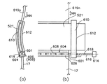
図13に骨盤受け部7xx(図6)を構成する骨盤支持盤17、腰椎部伸縮板521及び背もたれ主盤619nの連結の態様を示す。腰椎部伸縮板521は、伸縮板27(図11、図12などに示す)と同様の構成の伸縮板である。図13において、骨盤支持盤17の上端と腰椎部伸縮板521の下端とが回動軸601を介して軸着している。回動軸601は一対の軸受け606、608とともにヒンジ604を構成し、軸受け606が骨盤支持盤17の上端と、軸受け608が腰椎部伸縮板521の下端とそれぞれ結合している。即ち骨盤支持盤17の上端と腰椎部伸縮板521の下端とがヒンジ604を介して連結している。腰椎部伸縮板521の上端は背もたれ主盤619nの下端と固定的に結合している。
FIG. 13 shows how the
腰椎部伸縮板521の横幅方向の両端部には長尺案内穴610をそなえる長尺案内板612が係合している。腰椎部伸縮板521は、長尺案内穴610に挿通され、不図示の多関節ロボットアームにより矢印NN方向に駆動される背もたれ主盤619nの移動に伴って長尺案内穴610の長手方向の内壁面に沿って摺動する。
A
背もたれ主盤619nは自身の傾斜につれて下降するように多関節ロボットアームにより駆動される。あるいは、又は、着座する人の体形に合わせて上下する。
The backrest
長尺案内板612は下端部で回動軸601と軸着し、回動アクチュエータ614により、接続レバー616を介して回動軸601の軸心618を軸心として回動可能とされている。回動アクチュエータ614は骨盤支持盤17に不図示の固定部材を介して固定されている。
The
背もたれ主盤619、頚椎支持部2xxを構成する頚部伸縮板、後頭支持部1xxを構成する後頭部受け盤の構成及び一連の連結の態様も、図13に示す骨盤支持盤17、腰椎部伸縮板521、背もたれ主盤619nの構成及び一連の連結の態様と、形状及びサイズの違いはあっても、同様である。
The configuration of the backrest main plate 619, the cervical elastic plate constituting the cervical vertebra support portion 2xx, the occipital receiving plate constituting the occipital support portion 1xx and a series of connection modes are also shown in FIG. The configuration of the backrest
図7〜図9に示す態様においては、骨盤支持盤17は、骨盤部13(図6)の側面も支える立体的な容器状の形状のものであってもよい。又、伸縮板27も、各短冊板45を自身の長手方向に略孤状に湾曲した形状、あるいは自身の長手方向及び短幅方向に略孤状に湾曲した形状とすることにより、大腿部11の根元の側面も支える立体的な形状とすることが出来る。このような態様の一例を図14に示す。
7 to 9, the
図14は、着座した人10がほぼ図1、図4に示す状態で傾斜するときの立体的な容器状の形状の骨盤支持盤17rと、立体的な形状の伸縮板27rとの位置及び伸縮板27rの伸縮状態の変化の様子を模式的に示す。伸縮板27rは、骨盤支持盤17rの前縁に接続されて前方に延出されている。伸縮板27rは複数の短冊板45rが簾状に配列し、隣接の短冊板45r同士が図11に示す係合の態様で互いに係合している。
FIG. 14 shows the position and expansion / contraction of the three-dimensional container-shaped
(イ)、(ロ)、(ハ)はそれぞれ図1におけるS1、S1´、S2の状態あるいは図4におけるSS1、SS3、SS4の状態ほぼ対応する。イ−1、イ−2、イ−3は伸縮板27rの断面でみた配列状態である。姿勢S1(SS1)から姿勢S2(SS4)に移行するにつれ腰椎支持部5xxは傾斜してゆく。又、姿勢S1(SS1)から姿勢S2(SS4)に移行するにつれ回動軸心PP2は下降する。但し、腰椎支持部5xxと骨盤支持盤17rとは腰椎支持部5xxが傾斜してゆくあいだ互いの成す角度が一定であってもよい。
(A), (b), and (c) substantially correspond to the states of S1, S1 ′, and S2 in FIG. 1 or the states of SS1, SS3, and SS4 in FIG. A-1, A-2, and A-3 are the arrangement state seen in the cross section of the expansion-
本発明の態様の他の一例を説明する。図15の斜視模式図に示すように、本発明の椅子2nyは、後頭支持部1xx、頚椎支持部2xx、胸背支持部4xx、腰椎支持部5xx、骨盤支持部7xx及び臀部−大腿根元部支持部8xxが一枚の伸縮板23xにより構成される。伸縮板23xは、複数の伸縮板が丈方向に連結されたものであってもよい。又、座部4の後端と、伸縮板23xの前端65xとは固定用部材103を介して連結されている。
Another example of the aspect of the present invention will be described. As shown in the schematic perspective view of FIG. 15, the chair 2ny of the present invention includes a occipital support portion 1xx, a cervical vertebra support portion 2xx, a chest back support portion 4xx, a lumbar support portion 5xx, a pelvis support portion 7xx, and a buttocks-femoral root support. The portion 8xx is constituted by a single
伸縮板23xの両側縁部が断面コの字状の長尺ガイド54xの溝に挿入されて、伸縮板23xの丈方向の面形状が長尺ガイド54xにより規制され決定される。
Both side edges of the
長尺ガイド54xは、後頭支持部1xx、頚椎支持部2xx、胸背支持部4xx、腰椎支持部5xx、骨盤支持部7xx及び臀部−大腿根元部支持部8xxに対応する、後頭部ガイドユニット1g、頚椎部ガイドユニット2g、胸背部ガイドユニット4g、腰椎部ガイドユニット5g、骨盤部ガイドユニット7g及び臀部−大腿根元部ガイドユニット8gの各ガイドユニットから構成される。
The
図16(a)、(b)に、図15における頚椎部ガイドユニット2gと胸背部ガイドユニット4gとが軸心Jを軸に回動する不図示の軸着装置を介して、連結された状態の側面模式図を示す。図16(c)は図16(b)のXA方向の断面端面模式図、図16(d)は図16(b)のXB方向の断面端面模式図である。伸縮板23xは、軸心J(PP3に相当)を軸に回動する軸着装置54xを介して連結された頚椎部伸縮板56xと胸背部伸縮板58xとに分割されている。なお、軸着装置は、軸着部材と被軸着部材とが軸着されて成るものであり、軸着部材が一の部材と連結され、他の部材が被軸着部材と連結されることにより、一の部材と他の部材とがその軸着装置を介して軸着するものである。軸着装置を不図示の回動アクチュエータに接続することにより、一の部材を他の部材に対して回動させることが出来る。かかる構成により、頚椎部ガイドユニット2gを胸背部ガイドユニット4gに対して軸心Jを軸に相対的に回動し、従って、これらのガイドユニットにそれぞれ支持される頚椎部伸縮板56xと胸背部伸縮板58xとが軸心Jを軸に相対的に回動する。
16 (a) and 16 (b), the cervical
腰椎部ガイドユニット5gと骨盤部ガイドユニット7gとの連結の態様も、図16に示す機構が採用される。即ち、伸縮板23xが、リクライニングポイントPP2を介して連結された腰椎部伸縮板66xと胸背部伸縮板68xとに分割されてそれぞれが腰椎部ガイドユニット5gと骨盤部ガイドユニット7gに支持されて、腰椎部伸縮板66xと胸背部伸縮板68xとが軸心J(PP2に相当)を軸に相対的に回動する。なお、図16における()付きの符号は部材同士のかかわりの状態を説明するためのものであり、実際の形状を必ずしも示すものではない。
The mechanism shown in FIG. 16 is also used for the connection between the lumbar
図17(a)に胸背部ガイドユニット4gと腰椎部ガイドユニット5gとがロボットアーム70xを介して互いに相対的に進退する状態の側面模式図を示す。図17(b)は図17(a)のXC方向の断面端面模式図である。胸背部ガイドユニット4gは、腰椎部ガイドユニット5gの溝62xに挿入されて溝62xに沿って丈方向に摺動する。ロボットアーム70xは、直動アクチュエータ72x、回動アクチュエータ74x、76xから構成される。伸縮板23xは、固定部材87xを介して連結された胸背部伸縮板86xと腰椎部伸縮板88xとに分割されている。固定部材87xは胸背部ガイドユニット4gの下端に固定されている。
FIG. 17A is a schematic side view showing a state in which the chest back guide
この機構においては、図17(c)に示すように、固定部材87xを用いることなく、伸縮板23xが分割されずに胸背部ガイドユニット4gから腰椎部ガイドユニット5gにわたって配されてもよい。
In this mechanism, as shown in FIG. 17C, the
後頭部ガイドユニット1gと頚椎部ガイドユニット2gとの連結の態様も、図17に示す機構が採用される。この場合、伸縮板23xは、固定部材76xを介して連結された頚椎部伸縮板56xと後頭部伸縮板78xとに分割されている。なお、図16、図17における()付きの符号は部材同士のかかわりの状態を説明するためのものであり、実際の形状を示すものではない。
The mechanism shown in FIG. 17 is also used for the connection between the
伸縮板23xの構成の一例を図18に示す。伸縮板23xは複数枚の短冊板45xを互いに少なくとも部分的に重なりつつ横幅方向に平行に配して構成される。各短冊板45xは、両端部それぞれに抜け止め49xを頭頂に有する突起47xを備える。突起47xは短冊板45xの長手方向に沿った片縁の近傍に配される。又、各短冊板45xには両端部それぞれに短冊板45xの短幅方向に延びる長溝51xが形成されている。長溝51xは、短冊板45xの突起47xが突出する面とは反対がわの面に形成され、長溝51xの長手方向の側面が奥方向にえぐられて、長溝51xの長手方向の開口縁部52xが長溝51xの短幅方向に内側に向けて延出されている。
An example of the configuration of the
図19に示すように、短冊板45xを上下に重畳し、下側の短冊板45x1の突起47xを上側の短冊板45x2の長溝51xに挿入させて、短冊板45x1と短冊板45x2とが係合する。抜け止め49xが開口縁部52xに当止して、長溝51xに挿入された突起47xが長溝51xから外れないようにされ、突起47xが長溝51xに案内されて長溝51xの長手方向に沿って摺動し、これにより、上下の短冊板45xが互いに短幅方向にずれ、複数の短冊板45xが簾状に配置され伸縮板23xが構成される。なお、最上段の短冊板45xUは突起47xを備えない。
As shown in FIG. 19, the
伸縮板23xとしては、図12に示す伸縮板134dや、その他の公知の構造を有するものであってもよい。
The
本発明の更に他の態様の一例を図20に示す。図20においては、椅子2aaが横幅方向に可撓性の簾状板61を備え、簾状板61の湾曲により着座した人の頭頂から客部に至る外面の丈方向の曲面の形状が形成される。簾状板61は、多数の長尺の部材191が簾状に配され、隣接の長尺の部材191同士が可撓的に結合されて成る。簾状板61は簾状板61両側縁に係合する断面コの字状のガイドレール63を備え、ガイドレール63の長手方向に沿って移動可能とされている。図21に簾状板61とガイドレール63との係合状態を示す。ガイドレール63は複数個のパートに分割されており、各パートの位置により簾状板61の作る曲面の形状が変わる。
An example of still another aspect of the present invention is shown in FIG. In FIG. 20, the chair 2aa includes a flexible bowl-shaped
簾状板61の下端65は固定用部材103を介して座部4の後端に軸着もしくは固定されている。簾状板61の上端部67は収納箱69に不図示の巻き込み手段により巻き込まれて収納され、簾状板61は不図示の付勢手段により簾状板61が巻き込まれる方向に付勢されている。
The
図22に示すように、ガイドレール63は上から順に、後頭パート71、頚椎パート73、胸背・腰椎パート75、骨盤パート77、伸縮パート79に分かれる。
As shown in FIG. 22, the
後頭パート71と頚椎パート73との連結、及び頚椎パート73と胸背・腰椎パート75との連結は剛になされる。胸背・腰椎パート75と骨盤パート77とは胸背支持部4xxと骨盤受け部5との境界に位置する骨盤部回動部83を介して軸着されている。骨盤パート77と伸縮パート79とは互いに係合関係にある。伸縮パート79の前端は座部4の後端の固定用部材103に軸着もしくは固定されている。
The connection between the
簾状板61は複数の棒状部材あるいは短冊状部材が簾状に連結されて成る。棒状部材あるいは短冊状部材が可撓性の連結部材を介して連結されていてもよい。あるいは、短冊状部材同士が自身の長手方向を回動軸心として互いに係合して連結されていてもよい。
The bowl-shaped
図23に簾状板61の態様の一例を示す。図23においては、簾状板61aは、簾状に配された多数の長尺矩形中空の棒状部材197が一対のローラチェーン183a、183bを介して、棒状部材197の両端部をローラチェーン183a、183bに渡して連結される。ローラチェーン183a、183bの継手リンクプレート194を舌状に突き出してベンドアタッチメント184とし、各ベンドアタッチメント184に棒状部材197の両端部がボルト185、ナット186でそれぞれ固定される。継手リンクプレート194は継手リンクプレート194を貫通する継手ピン295、およびこの継手ピンに装着されて継手リンクプレート194の抜けを防止する不図示の割りピンを備える。
FIG. 23 shows an example of the form of the bowl-shaped
簾状板61の態様の他の一例を図24に示す。図24において、簾状板61bは、簾状に配された多数の棒部材198が連結綱499を介して数珠繋ぎ状に連結される。連結綱499は各棒部材198に形成された貫通孔200に挿通され、両端に抜け止め部201を備える。
Another example of the form of the bowl-shaped
簾状板61は建物の出入り口等に使用する巻上げ式シャッタ ーのような構造物であってもよい。このような態様の一例を図25に示す。図25において、簾状板61cを構成するスラット173pは左右方向に長い帯状の構成で、上下の縁を互いに逆回り螺旋状に折り曲げて係合縁175a、175bを構成している。この構成に於いては隣接するスラット173p、173左右逆側の上下の係合縁175a、175bを合わせて下側のスラット173pを上側のスラット173pに対して横方向にスライド移動して所定位置にもたらすと、下側のスラット173pは上側のスラット173pに対して横方向の移動並びに屈曲のみが可能に連接される。このようにして上下に設けた係合縁175a、175bを横方向のスライド操作により順次係合させて多数枚のスラット173p、173p…を屈曲自在に連接し簾状板61cが構成される。
The bowl-shaped
簾状板61の態様の更に他の一例を図26に示す。図26において、簾状板61dを構成する棒状部材80が簾状に配されて可撓性のシート82に接着されている。
FIG. 26 shows still another example of the form of the bowl-shaped
図27に図22における胸背・腰椎パート75と骨盤パート77との連結の構成の一例を示す。図27において、骨盤部回動部83が遊星歯車装置91を含んで構成される。遊星歯車装置91は太陽歯車92と、アーム94と、遊星歯車96で構成される。アーム94は連結腕97の一端に固着される。連結腕97の他端に歯車片101が固着されている。歯車片101の歯は、爪158に噛み込み可能とされている。爪158は、支点160を中心に揺動する揺動レバー161の一端に配され、揺動レバー161の他端のハンドルレバー163を動かして、歯車片101の歯と爪158に噛み込みと開放が自在になされ、この噛み込みにより、アーム94が一時的に固定される。アーム94がアクチュエータ(サーボモータなど)により駆動され、これにより、遊星歯車96が回動する方式であってもよい。
FIG. 27 shows an example of the connection configuration of the chest back /
遊星歯車96の側面に胸背・腰椎パート75が固着されている。胸背・腰椎パート75は側面視略円弧状のガイドレールから成る。遊星歯車96が矢印Dの方向に回転するにつれて、胸背・腰椎パート75は直立の状態(イ)から斜めの状態(ロ)を経て略水平に倒された状態(ハ)に移動する。これにより、背もたれ盤(不図示)のリクライニングポイント60が略a→b→cに弧状に上から下へ可逆的に移動する。即ち、このとき、リクライニングポイント60は、斜め後方に下降し次いで略鉛直方向に下降し次いで斜め前方に下降する略弧状の軌跡をたどる。
A chest back /
図28に、骨盤パート77と、伸縮パート79との係合関係の態様の一例を示す。伸縮パート79は、前端111が固定用部材103を介して不図示の座部4の後端に固定されている。座部4の後端に軸着されていてもよい。伸縮パート79は、後端部105が側面視略円弧状のガイドレールから成る。後端部105の溝207に骨盤パート77の下端部109が緩やかに嵌め込まれ後端部105と下端部109とが略滑らかな曲線状に連結される。骨盤パート77が下降するにつれ下端部109が伸縮パート79に係合したまま前端111に向けて前進し、これにより、下端部109と前端111との距離が短くなる。
In FIG. 28, an example of the aspect of the engagement relation of the
胸背・腰椎パート75を丈方向に伸縮させて胸背・腰椎パート75に保持される簾状板61の丈方向の長さを人10(図22)の体格に合わせて調節することが出来る。この態様の一例を図29に示す。伸縮可能な胸背・腰椎パート75aは、胸背・腰椎パート75aの上部を構成する上部パート113、中央部を構成する中央パート115、下部を構成する下部パート117から成り、隣接の各パートは境界の部分で互いに係合している。即ち、上部パート113の下端部中央パート115の上端部の溝の部分に、下部パート117の上端部が中央パート115の下端部の溝の部分に、それぞれ緩やかに嵌め込まれている。
The length in the length direction of the bowl-shaped
胸背・腰椎パート75aは、互いに反対方向に同時に直動する直動ロッド133、135を有する直動アクチュエータ137を備える。上部パート113が連結棒139を介して直動ロッド133に、下部パート117が連結棒141を介して直動ロッド135にそれぞれ固定される。中央パート115は連結棒148を介して直動アクチュエータ137とともに不図示の浮動ベースに固定される。下部パート117と上部パート113とが直動アクチュエータ137により駆動されて中央パート115を間にして互いに近接あるいは離反することにより胸背・腰椎パート75aが伸縮する。
The thorax /
胸背・腰椎パート75の湾曲の度合いを変化させて胸背・腰椎パート75に保持される簾状板61の丈方向の湾曲の度合いを人10(図22)の体格に合わせて調節することが出来る。この態様の一例を図30に示す。湾曲の度合いを変化可能な胸背・腰椎パート75bは、胸背・腰椎パート75bの上部を構成する上部パート113b、中央部を構成する中央パート115b、下部を構成する下部パート117bから成り、隣接の各パートは境界の部分で図29に示す態様と同様の態様で互いに係合している。
Changing the degree of curvature of the chest back /
胸背・腰椎パート75bは、回動アクチュエータ161a、161bを備える。上部パート113bが回動アクチュエータ161aに連結され、下部パート117bが回動アクチュエータ161bにそれぞれ連結され回動軸163a、163bをそれぞれ軸心として回動し、これにより胸背・腰椎パート75bの湾曲の度合いを変えることが出来る。回動アクチュエータ161a、161b及び中央パート115bは不図示の浮遊盤に対して固定される。又、他の態様においては、回動アクチュエータ161a、161bに変えて多関節ロボットアームにより上部パート113bと下部パート117bとをそれぞれ駆動して胸背・腰椎パート75bが更に伸縮する機能を備えるようにすることが出来る。
The thorax /
図31に頚椎パート73の構成の一例を示す。図31において、頚椎パート73aは、略孤状に長手方向に湾曲した板バネ151に複数のガイドレールエレメント440が一列に配されて不図示の鋲などを介して接合されて成る。ガイドレールエレメント440がこの態様で集合して略孤状に長手方向に湾曲した溝143を有するガイドレール部145が形成されている。溝143は横幅方向の内側に面して開口している。図31(a)は頚椎パート73aの側面図、図31(b)は図31(a)のZ3−Z3方向の断面端面図、図31(c)はガイドレールエレメント440の側面図、図31(d)はガイドレールエレメント440の平面図である。板バネ151を例えば図34に示す態様と同様の態様で湾曲することにより、頚椎パート73aが更に湾曲する。
FIG. 31 shows an example of the configuration of the
本発明の又更に他の態様においては、図32の側面模式図に示すように、本発明の椅子2mは、頭部の後方への反り曲りにつれて湾曲する湾曲板23から成る頚椎支持部23mを備える。湾曲板23は上端で後頭支持部25mと、下端で胸背支持部4xmと連接されている。湾曲板23の湾曲につれて後頭支持部25mが傾斜するので、湾曲板23の位置が胸背支持部4xmと頚椎支持部23mとのリクライニングポイント(回動軸心)PP3となる。
In still another embodiment of the present invention, as shown in the schematic side view of FIG. 32, the
湾曲板23は図33に示すように、横幅方向を軸心線として孤状に湾曲した板バネ53の湾曲の外側の面に複数の短冊状のクッション材55が簾状の配列で貼り付けられて成る。クッション材55の外面を連ねた面が、頚椎部19xの丈方向の曲面に沿う形状となっている。
As shown in FIG. 33, the
湾曲板23は例えば図34に示す機構により横幅方向を軸心線として更に湾曲させることが出来る。図34においては、板バネ53の上端部から突出したレバー455の先端部575を胸背支持部4xmに関して固定されている直動アクチュエータ59により押しやることにより板バネ53の各部にほぼ均一に曲げトルクが作用して板バネ53の曲率が大きくなる。この湾曲に伴って後頭支持部25m(図32)が傾斜する。
The
本発明においては、湾曲板23が撓むかわりに、湾曲板23の下端と胸背支持部4xmの上端とが回動アクチュエータを介して回動可能に軸着連結され、湾曲板23が胸背支持部4xmに対して傾斜する構成であってもよい。この傾斜に伴って後頭支持部25mが傾斜する。
In the present invention, instead of bending the bending
本発明の椅子2における頚椎支持部2xxを構成する腰椎部伸縮板521(図13)、や頚部伸縮板や、椅子2ny(図15)における、伸縮板23xの頚椎支持部2xxや腰椎支持部5xxを構成する部分は、左右両端部で長尺案内板612や長尺案内板612hや長尺ガイド54xで支えられているだけであり、中央部分での人体による荷重で撓みやすく、中央部分での所定の湾曲が確保しにくいことがある。
The lumbar elastic plate 521 (FIG. 13), the cervical elastic plate constituting the cervical support 2xx in the
本発明においては、図35に示すように、伸縮板で構成される頚椎支持部2xxや腰椎支持部5xxを裏側からバックアップして支えるバックアップ体730が備えられてもよい。バックアップ体730は頚部伸縮板23nや腰椎部伸縮板521や伸縮板23xのような伸縮板732の裏面に面接して伸縮板732の表面(人体と当接する面)の曲面を所定の形状に形成する。
In the present invention, as shown in FIG. 35, a
バックアップ体730の伸縮板732と面接する表面の丈方向の曲率は可変とされており、人体の姿勢あるいは伸縮板732の丈方向の曲率に応じて変えることが出来る構成となっている。
The curvature in the length direction of the surface of the
バックアップ体730の一例として、図36に示すような巻体700及び巻き取り構造704が用いられてもよい。巻体700は、多数の棒状部材が可撓性の連結部材あるいはヒンジを介して簾状に連結した、例えば、図24〜図26にそれぞれ示す簾状板61b、簾状板61c、簾状板61dのような簾状シート702が巻き取られて成る。
As an example of the
図36においては、巻き取り構造704が簾状シート702を巻き取る水平に配された主巻き芯708、副巻き芯710を備える。主巻き芯708を不図示の駆動手段により回転させて、主巻き芯708に簾状シート702を一方の端部のがわから巻き取り巻体700となす。副巻き芯710を不図示の駆動手段により回転させて、巻体700から巻き出された簾状シート702を簾状シート702の他方の端部のがわから副巻き芯710に巻き取る。符号703はガイドバーである。
主巻き芯708に巻き取られた簾状シート702の量(長さ)を変えることにより図36(a)から図36(b)への状態とあるいはその逆へと巻き取り巻体700の径を変える。
In FIG. 36, the winding
By changing the amount (length) of the bowl-shaped
巻体700の径を可変とする他の態様の一例を図37に示す。図37において、巻体700aは中空構造のシート750が巻き芯752に巻き取られて成る。シート750の一端は巻き芯752に固定され、他端は固定棒756に固定されている。
An example of another mode in which the diameter of the
シート750は、表裏2層の膜状シートが外部に対して封止された中空部760を間にして重畳されてなり、中空部に空気や水等の液体を自在な量で封入することの出来る構成となっている。中空部に封入される液体の量を変えるとシート750は厚みTHが変わる。図37(a)は厚みTHが大きい場合であり、巻体700の径は大きい。図37(b)は厚みTHが小さい場合であり、巻体700の径は大きい。図37(b)は中空部に封入された液体の量が減少させられて厚みTHが小さい場合であり、巻体700の径は小さい。図37(a)の状態から図37(b)の状態に移行するときには、巻き芯752が不図示の回転手段により回転して巻き芯752へのシート750の巻き回し回数が増加する。又、このとき、固定棒756が不図示の移動手段により巻き芯752に近づく方向に移動してもよい。
The
バックアップ体730の更に他の一例を図38に示す。バックアップ体730が、軸を水平にした断面略楕円形あるいは略卵形の筒体あるいは柱体762から構成される。柱体762を断面縦長に配した図38(a)の状態、断面長幅方向を斜向して配した図38(b)の状態、断面横長に配した図38(c)の状態、のそれぞれで、伸縮板732の裏面と面接する柱体762表面767の丈方向の曲率が変わる。図38(a)から図38(c)への状態の変化は柱体762を自身の軸心765等の回転軸の回りに不図示の回動手段により回動させ、かつ不図示の移動手段により自身の軸心を水平に保ちつつ所定の方向に所定量移動させて実現される。
Another example of the
自身の軸心等の回転軸の回りに回動させる筒体あるいは柱体の外断面の形状は、外断面の曲率が周方向に漸増する図39に示すような形状を有するで柱体769であってもよい。柱体769を軸心771の回りに回動させて伸縮板732の裏面と面接する柱体769表面の丈方向の曲率を変える。
The shape of the outer cross-section of the cylinder or column rotated around the rotation axis such as its own axis is such that the curvature of the outer cross-section gradually increases in the circumferential direction as shown in FIG. There may be. The
更に、本発明の椅子においては、身体に接する面を図40に示すハッチングされた部分171、173のような形状に3次元的に形成し、このような面をそれぞれ有する首部規制壁、背・腰部規制壁を備えることにより、着座した人の姿勢を3次元的に規制することが出来る。
Furthermore, in the chair of the present invention, the surface that contacts the body is three-dimensionally formed in the shape of hatched
この規制により、ハッチングされた部分(首部規制面)171、ハッチングされた部分(背・腰部規制面)173が身体を側方から内側に圧迫し、この圧迫により、その部分の身体を丈方向にストレッチする応力が発生し、身体の後頭部17x,胸背部15を経て腰椎部21xに至る部分(図6)をストレッチ状態に保つことが出来る。
By this regulation, the hatched part (neck regulating surface) 171 and the hatched part (back / waist regulating surface) 173 press the body from the side to the inside, and this compression causes the body of the part to move in the length direction. A stretching stress is generated, and a portion (FIG. 6) that reaches the
このストレッチ力は、身体の牽引治療におけるストレッチ力に相当する作用を有し、牽引治療の代替としてこのような構成の本発明の椅子に所定時間着座することが有効である。又、このような椅子を日常使用することが身体の頭頚部19から胸背部15を経て腰椎部21xに至る部分に不自然な力が作用することを防止する。又、この本発明の椅子の使用により、従来の椅子の使用やその他無理な姿勢の持続により、着座により不自然な力が身体に作用して牽引治療を要するような状態になりやすいことが防止される。
This stretch force has an action equivalent to the stretch force in the body traction treatment, and it is effective to sit on the chair of the present invention having such a configuration for a predetermined time as an alternative to the traction treatment. Further, daily use of such a chair prevents an unnatural force from acting on the part from the head and
このような形状を実現するため一例として、図20に示す椅子2aaにおける簾状板61を構成する長尺の部材191として、図41に示すような表面183が曲面状の短冊状板193が用いられる。図42に示すように、異なる表面曲面形状の短冊状板193a、193b、193c・・・を簾状に配して背・腰部規制面173(図40)が形成され、この面が背・腰部規制壁673の面となる。
As an example for realizing such a shape, a strip-shaped
図43は異なる表面曲面形状の短冊状板193x、193y、193z・・・を簾状に配して首部規制面171(図40)が形成され、この面が首部規制壁671の面となった態様である。
In FIG. 43, strip-
長尺の部材191としては図44に示すように、長尺矩形短冊板195の上面に長尺の曲板297が間隔をおいて固定用支柱部材199を介して固定されている棒状の部材193xのような態様であってもよい。この場合は、C−C方向にみて図45に示すように、可撓性の簾状板を構成する隣接の曲板297同士が短幅方向の縁部を蛇の腹状に一部重ね合わせて配されることにより、複数の曲板297を円滑に集合させて、複数の曲板297の表面を連ねて背・腰部規制面173や首部規制面171を着座する人の姿勢や体形等に応じて円滑に形成することが出来る。この態様は、伸縮板23x(図19)を用いた椅子2ny(図15)における短冊板45x(図18)にも適用される。
As the
首部規制面171、背・腰部規制面173を着座する人の姿勢や体形等に応じて円滑に形成する他の態様においては、図46に示すように、エアスポンジ412、414が使用されてもよい。エアスポンジ412、414は首部規制面171、背・腰部規制面173それぞれに表面が当接するように椅子2xの胸背支持部4xp及び頚椎支持部2xpに配される。
In another embodiment in which the
エアスポンジ412、414は積極的に着座する人の頭部規制面171、胸背・腰椎部規制面173に対応する部位を押し上げる機能を有するので、これらの部位のストレッチ効果が更に高い。
Since the
首部規制壁、背・腰部規制壁は、首部規制面171、背・腰部規制面173にならった面形状を有するそれぞれ一対の曲板から構成されてもよい。これらの曲板を、椅子の、着座した人の首と背・腰のそれぞれの両側面に相当する位置に配することにより、首部規制壁、背・腰部規制壁となる。これらの各保護壁がアクチュエータにより左右に駆動されてもよい。これにより、着座した人の体形や条件に合わせた各保護壁の位置を設定できる。更に、アクチュエータにより一対の対向の保護壁を互いに近接方向に付勢することにより、積極的に首部や背・腰部を側面から圧迫しいて上述のストレッチ効果を高めることが出来る。
The neck restriction wall and the back / waist restriction wall may be formed of a pair of curved plates each having a surface shape similar to the
一対の曲板を互いに近接させる手段としては、例えば、図47に示す間隔可変装置306kが用いられる。間隔可変装置306kは、椅子の幅方向に関して一端に配された軸受けボックス324、他端に配された駆動ボックス326、軸受けボックス324と駆動ボックス326との間に互いに平行に配された水平摺動シャフト320、ネジシャフト322を備えて構成される。水平摺動シャフト320は、軸受けボックス324及び駆動ボックス326の手前(椅子2aに関して)側上端部に配されている。また、ネジシャフト322は、軸受けボックス324及び駆動ボックス326の奥側下端部に配されている。
As a means for bringing the pair of curved plates close to each other, for example, an
そして、左右一対の水平移動部材357、358が水平摺動シャフト320及びネジシャフト322にまたがって左右へ移動(水平移動)可能に取り付けられている。これらの水平移動部材357、358にはそれぞれ、支持用アーム361、362を介して部材301、302が取り付けられている。部材301、302として一対の曲板の各々を用いることにより、その曲板を互いの近接、離反させることが出来る。
A pair of left and right horizontal moving
駆動ボックス326には、図示しないモータ、減速ギア列が収納されている。これらのモータ、減速ギア列によりネジシャフト322が回転する。ネジシャフト322には、左半部と右半部とに互いに逆向きに2つの雄ねじ部が設けてある。また、水平移動部材357、358のそれぞれには、ネジシャフト322における各雄ねじ部にねじ合う雌ねじ部が設けてある。したがって、ネジシャフト322が回転すると、その左半部と右半部とにそれぞれねじ合っている水平移動部材357、358が互いに逆に左または右方向へ移動する。これにより、部材301、302は水平摺動シャフト320上を左右に移動する。間隔可変装置の態様は間隔可変装置306kに限定されず、例えば、部材301、302が直動アクチュエータにより直接駆動されてもよい。
The
着座した人の上半身の傾斜に伴い、背中のリクライニングポイントが、上半身が後方に傾斜するにつれて斜め後方に下降し次いで略鉛直方向に下降し次いで斜め前方に下降する略弧状の軌跡をたどり、又、姿勢S1のときから上半身が後方に傾斜するにつれて、位置Kが位置Tに近づいてゆく図1に示す状態を実現する本発明の他の態様を図48に示す。図48は、椅子(図48には全体像は不図示)の腰椎支持盤12t及び骨盤支持盤17tに連結されて両者を傾斜させる駆動装置70の作動を説明する模式図であり、図48(a)は側面図、図48(b)は正面図である。駆動装置70は椅子の側部に設置される。駆動装置70はフレーム等の固定部102に固定されて立設される支柱104の先端部に一の角度変更手段307を介して一端部で軸着するアーム106と、アーム106の他端部に一端部で他の角度変更手段112を介して軸120で軸着し、腰椎支持盤12tに固定される腰椎支持盤支持用アーム110を含んで構成される。
As the upper body of the seated person inclines, the reclining point of the back follows a substantially arc-shaped trajectory that descends obliquely backward, then descends substantially vertically and then descends obliquely forward as the upper body inclines backwards. FIG. 48 shows another aspect of the present invention that realizes the state shown in FIG. 1 in which the position K approaches the position T as the upper body tilts backward from the posture S1. FIG. 48 is a schematic diagram for explaining the operation of the driving
更に、駆動装置70は骨盤受け部を構成する骨盤受けユニット130を備える。骨盤受けユニット130は、自身の長手方向を軸に弧状に曲った曲板132と、自身の長手方向を軸に可撓である可撓板134から成る。曲板132は骨盤を背後から受け、略水平の状態に向けて傾斜可能な骨盤部背面受け盤319を構成する。可撓板134は臀部下面受け盤349を構成する。臀部下面受け盤349は、骨盤部の下面部を受け、骨盤部背面受け盤319の下端から骨盤部背面受け盤319と略直交する方向に傾斜方向を徐徐に変えつつ椅子の前方に向けて延出される。
Further, the driving
曲板132と可撓板134はともに自身の長手方向を水平に向けて配され、曲板132の下縁と可撓板134の上縁とが軸着部337を介して枢着している。
The
曲板132の上縁の長手方向にみた端は、軸着棒136を介して腰椎支持盤支持用アーム110の下端部に枢着している。軸120と軸着棒136とは共通の部材から成ってもよい。
An end of the upper edge of the
骨盤受けユニット130は、更に、案内盤140を椅子の側部に備える。案内盤140には、可撓板134の側縁部を全て挿入させて可撓板134の動きを案内する案内溝138が形成されている。案内溝138は、骨盤受け部のがわから座部4のがわに至る略前後方向に形成され、骨盤受け部のがわでは、可撓板134が案内溝138に挿入されて、可撓板134の上面が骨盤受け面の臀を支持する部分の面となるように案内される。
The
可撓板134の座部4のがわは、案内溝138に案内されて座部4を構成する座盤142の下方に潜りんで位置する。
The
アーム106の角度変更手段307を軸心とする回動により、腰椎支持盤12tが傾斜するとともに腰椎支持盤12tのリクライニングポイント(回動軸心)が下方に孤を描くように下降する。即ち、腰椎支持盤12tのリクライニングポイント60が略a→b→cに弧状に上から下へ、またその逆にと可逆的に移動し、リクライニングポイント60は、斜め後方に下降し次いで略鉛直方向に下降し次いで斜め前方に下降する略弧状の軌跡をたどる。
By turning about the angle changing means 307 of the
又、腰椎支持盤支持用アーム110の角度変更手段112の軸心とする回動により、腰椎支持盤12tの傾きが変わる。又、アーム106が下方に回動するにつれて、曲板132が下方に押しやられ、曲板132の下縁を介して可撓板134が案内溝138に案内されつつ前方に押しやられる。この押しやりにより、座盤142の後端144と可撓板134の後端345即ち曲板132の下縁との距離Lが減少し、骨盤受け面の臀を支持する部分の面が前後方向に短縮される。
Further, the tilt of the
角度変更手段307と角度変更手段112は所定の角度に設定でき、かつ設定された角度が固定される機能を有する。例えば、腰椎支持盤支持用アーム110は、人が背をほぼ垂直にした状態に対応するP1の状態(図1)から、背をほぼ45度倒したP2、背がほぼ水平状態に倒れたP3の状態に変化させることが出来る。これに対応して、アーム106は、Q1、Q2、Q3の状態に変化させることが出来る。腰椎支持盤支持用アーム110は、R1、R2、R3の状態に変化させることが出来る。
The
角度変更手段307と角度変更手段112はこのような機能を有するものであれば態様を問わないが、一例として、ラチェットを備えた金具と、ラチェットに咬合する爪を備えた金具とが軸支され、この爪の作動を制御するフリーカムとの組合せで、関節の折畳み展開を、複数段階で角度を調節するものが挙げられる。 The angle changing means 307 and the angle changing means 112 are not particularly limited as long as they have such a function, but as an example, a metal fitting provided with a ratchet and a metal fitting provided with a claw engaged with the ratchet are pivotally supported. A combination with a free cam that controls the operation of the claw can be used to adjust the angle of the joint in a plurality of stages.
又、ワンウェイクラッチの機構原理を応用して、関節部に軸支した、二個の金具の内、回動金具側に支軸穴と同心の円弧面を備え他方の金具に円弧面と同形成の曲面を対向させ、該間隙の片方を狭くして、支軸を保持するケースの内底に固定し、該間隙にローラを介在させ、ローラを押圧するバネ機構により、同心円周で回動する円弧面に対向曲面が構成する狭少間隙曲面で、ローラを円弧面に押圧して、折畳み方向で任意の角度で停止して、後退方向に荷重が作用した時、ローラに摩擦力が作用して、円弧面に伴って転動し狭少間隙で、咬み合い作動で後退を阻止する無段階調節機構が挙げられる。 Also, by applying the mechanism principle of the one-way clutch, of the two brackets that are pivotally supported at the joint, an arc surface concentric with the pivot hole is provided on the rotating bracket side, and the other bracket has the same shape as the arc surface. Are opposed to each other, narrowed on one side of the gap, fixed to the inner bottom of the case holding the support shaft, a roller interposed in the gap, and rotated concentrically by a spring mechanism that presses the roller. This is a narrow gap curved surface with an opposing curved surface on the circular arc surface. When the roller is pressed against the circular arc surface and stopped at an arbitrary angle in the folding direction and a load is applied in the reverse direction, a frictional force is applied to the roller. Thus, there is a stepless adjustment mechanism that rolls along a circular arc surface and prevents retraction by biting operation with a narrow gap.
その他に、ラック・ピニオン機構によっても所定の角度に設定でき、かつ設定された角度が固定される機能が実現される。更に、角度変更手段112は腰椎支持盤支持用アーム110とアーム106のいずれか一方にパルスモータ等の電動アクチュエータ本体を固定し、他方にその電動アクチュエータの回動軸を直結し、電気信号により回動軸の回転角度を設定する機構であってもよい。角度変更手段307にも同様に電動アクチュエータが用いられてよい。
In addition, a function that can be set to a predetermined angle by the rack and pinion mechanism and the set angle is fixed is realized. Further, the angle changing means 112 fixes an electric actuator body such as a pulse motor to either the lumbar support
角度変更手段に電動アクチュエータが用いられた場合は電気信号により腰椎支持盤支持用アーム110とアーム106の動きを連動させることが出来る。又、この連動は歯車機構やリンク機構により機械的に行なうことも出来る。
When an electric actuator is used as the angle changing means, the movement of the lumbar support
図4に示すリクライニングポイントP1及び位置Kの移動を実現する態様の一例を図49の駆動装置70aに示す。図49(b)は図49(a)の正面模式図である。駆動装置70aにおいては、腰椎支持盤12の傾斜につれて、位置K(図4)に対応する位置KAが、位置T(図4)に対応する位置TAに向けて近づき、位置KAと位置TAとの距離が短縮するようになされている。駆動装置70aは椅子(全体像は不図示)の側部に設置される。駆動装置70aはフレーム等の固定部102に固定されて立設される支柱104の先端部に一の角度変更手段307を介して一端部で軸176により軸着するアーム106aと、アーム106a他端部に一端部で他の角度変更手段112を介して軸120で軸着し、腰椎支持盤12に固定される腰椎支持盤支持用アーム110を含んで構成される。
An example of a mode for realizing the movement of the reclining point P1 and the position K shown in FIG. 4 is shown in the
更に、駆動装置70aは骨盤受け部5を構成する骨盤受けユニット130aを備える。骨盤受けユニット130aは、自身の長手方向を軸に弧状に曲った曲板132と、自身の長手方向を軸に可撓である可撓板134から成る。曲板132は骨盤を背後から受ける骨盤部背面受け盤319を構成する。可撓板134は臀を支持する。
Further, the driving
曲板132と可撓板134はともに自身の長手方向を水平にして配され、曲板132の下縁と可撓板134の上縁とが軸着部437を介して枢着している。
The
曲板132の上縁の長手方向にみた端は、軸着棒136を介して腰椎支持盤支持用アーム110の下端部に枢着している。
An end of the upper edge of the
骨盤受けユニット130aは、更に、案内盤140aを椅子の側部に備える。案内盤140aには、可撓板134の側縁部を全て挿入させて可撓板134の動きを案内する案内溝138aが形成されている。案内溝138aは、骨盤受け部5のがわから座部4(図4)のがわに至る略前後方向に形成され、骨盤受け部5のがわでは、可撓板134が案内溝138aに挿入されて、可撓板134の上面が骨盤受け面の臀を支持する部分の面となるように案内される。
The
可撓板134の座部4のがわは、案内溝138aに案内されて座部4を構成する座盤142の下方に潜り込む状態に位置する。
The
又、案内盤140aには、曲板132の上縁端部180から横方向に突出する案内棒170の先端部を深さ方向に挿入し、長手方向に貫通させて曲板132の上縁の動きを案内するスリット溝439が形成されている。案内棒170、軸120及び軸着棒136は共通の部材から成る。なお、アーム106aは支柱104と反対がわの面に、長手方向に沿って案内溝172が形成されて、案内棒170の先端部174が挿入されている。
In addition, the
アーム106aが軸176を軸心として下方に回動すると、曲板132が下方に押しやられ、曲板132の下縁を介して可撓板134が案内溝138aに案内されつつ前方に押しやられる。この押しやりにより、座盤142の後端144と可撓板134の後端即ち曲板132の下縁146との距離LAが減少し、骨盤受け面の臀を支持する部分の面が前後方向に短縮される。
When the
同時に、案内棒170が案内盤140aに形成されたスリット溝439に案内されて前下に移動し、更にアーム106aが下方に回動すると、案内棒170がスリット溝439に案内されてほぼ鉛直下方に移動し、次いで下方かつやや後方に移動する。これらの移動に伴って案内棒170の先端部174が案内溝172に沿って移動する。スリット溝439の形状を変えることにより、所望の案内棒170の移動の軌道が得られる。
At the same time, the
腰椎支持盤支持用アーム110とアーム106aとは、遊星歯車機構等により連動されて駆動されてもよい。
The lumbar support
本発明においては、図50の説明模式図に示すように、腰椎支持盤支持用アーム110及び曲板132が所定の軌道に沿って移動するように、多関節のロボットアーム90により、プログラミングされて駆動されてもよい。ロボットアーム90は、不図示の回動アクチュエータそれぞれにより回動する関節491、493及び497と、不図示の直動アクチュエータにより前進後退する直動部496とが組み合わされて成り、リクライニングポイントが、所定の軌跡をたどるように、又、腰椎支持盤支持用アーム110及び曲板132が所定の傾き状態に傾くように、各アクチュエータが不図示の制御回路によってプログラミングされて駆動される。
In the present invention, as shown in the schematic diagram of FIG. 50, the lumbar support
前後方向に伸縮自在な可撓板を骨盤部用可撓板190として用いた骨盤受けユニットの一例として図51に示す骨盤受けユニット130bが挙げられる。図51の中央縦割り断面模式配置図に示すように、骨盤部用可撓板190の後部分は、曲板132に載置されて曲板132(図48など)とともに移動し、骨盤部背面受け盤319を構成する。骨盤部用可撓板190の前部分は、可撓板134に載置されて可撓板134上を摺動しつつ可撓板134とともに移動し臀を支持する。骨盤部用可撓板190の前先端部PPは不図示の固定手段によりフレームに対して固定された位置に保たれる。
A
更に、本発明においては、前後方向及び横方向に伸縮自在な骨盤部用可撓板が用いられてもよい。骨盤部用可撓板は例えばブタジエン系やイソプレン系等の合成ゴムから成る弾性樹脂板であってもよい。あるいは、多数のコイルバネが網目状に連結されてなるネットを、一対のターポリンのような可撓性のシートでサンドイッチ状にはさんで成る複合シートであってもよい。 Furthermore, in the present invention, a flexible plate for a pelvis part that can expand and contract in the front-rear direction and the lateral direction may be used. The flexible plate for the pelvis may be an elastic resin plate made of synthetic rubber such as butadiene or isoprene. Alternatively, it may be a composite sheet in which a net formed by connecting a large number of coil springs in a mesh shape is sandwiched between a pair of flexible sheets such as tarpaulins.
前後方向及び横方向に伸縮自在な骨盤部用可撓板が骨盤受けユニット130bに用いられると、骨盤受けユニット130bを幅方向に伸縮自在とし、側面を形成して骨盤を側面からも受け、かつ、図52に示すように、対向するその側面受け部の幅HHを可変とすることが出来る。図52においては、骨盤部用可撓板190の両側縁部の後部分192がそれぞれ幅規制ホルダ495により把持されて、幅規制ホルダ495の内側面とともに骨盤受け部の側壁面を形成する。幅規制ホルダ495は互いに面対称形の一対の部材201a、202aから成り、骨盤・臀部支持部5の両側端部に片方づつ対称に配され、曲板132(図51)と連動する。又、幅規制ホルダ495は不図示の間隔可変装置を備え、部材201a、202a間の間隔が可変とされている。
When a flexible plate for a pelvis part that can expand and contract in the front-rear direction and the lateral direction is used for the
図53(a)、図53(b)、図53(c)、図53(d)に図52のAA−AA方向、BB−BB方向、CC−CC方向、DD−DD方向、の断面端面模式図をそれぞれ示す。 53 (a), 53 (b), 53 (c), and 53 (d) are cross-sectional end faces in the AA-AA direction, BB-BB direction, CC-CC direction, and DD-DD direction in FIG. A schematic diagram is shown respectively.
間隔可変装置としては例えば図47に示す間隔可変装置306kを用い、部材301、302として部材201a、202a(図52)を取り付ける態様であってもよい。
For example, an
本発明においては、図54に示す椅子2hのように、胸背支持部4xxが胸背部受けシート804で構成されてもよい。又骨盤支持部7xxが骨盤部受けシート807で構成されてもよい。この場合、頚椎支持部2xx及び腰椎支持部5xxが、剛な板あるいは簾状の可撓性板や伸縮板(図11、図12、図18、図22、図24、図25、図26など)で構成される。胸背部受けシート804、骨盤部受けシート807は、ターポリンのような可撓性のシート、伸縮性のゴムシートのような可撓性かつ伸縮性のシートあるいはハンモック用ネットのような可撓性かつ伸縮性のネットで構成される。又、頚椎支持部2xx及び腰椎支持部5xxが、剛な板あるいは簾状の可撓性板や伸縮板(図11、図12、図18、図22、図24、図25、図26など)で構成される。この態様においては、人10が着座することにより胸背支持部4xxや骨盤支持部7xxの曲面が人10の体重による荷重により体形に応じて形成される。リクライニングポイントPP2、リクライニングポイントPP3における回動角度も、着座した人10の体形の変化に応じて人10の荷重で胸背支持部4xxや骨盤支持部7xxが変形あるいは変位することにより自ずと変わる。頚椎支持部2xxや腰椎支持部5xxは、不図示の駆動手段により、着座した人10の着座(傾斜)姿勢に応じて所定の配置状態になるように駆動される。
In the present invention, like the
胸背部受けシート804や骨盤部受けシート807は、側縁部が椅子2hの両側それぞれに配された不図示の固定部に固定されてもよい。この固定部は椅子2hの両側それぞれに互いに平行に長手方向を丈方向にして配された一対の棒状部材であってもよい。
The chest back receiving
胸背支持部4xxや骨盤支持部7xxのいずれかが可撓性シート、伸縮性シートあるいはネットで構成されて、他方が剛な部材で構成されてもよい。両者ともターポリンのような可撓性のシート、伸縮性のゴムシートのような伸縮性のシートあるいはハンモック用ネットのようなネットで構成される図54に示す態様が更に好ましい。 Either the chest back support part 4xx or the pelvis support part 7xx may be configured by a flexible sheet, an elastic sheet, or a net, and the other may be configured by a rigid member. The embodiment shown in FIG. 54, which is composed of a flexible sheet such as tarpaulin, a stretchable sheet such as a stretchable rubber sheet, or a net such as a hammock net, is more preferred.
このような態様においては、着座した人10の着座(傾斜)姿勢に応じて胸背支持部4xxや骨盤支持部7xxが、胸背部や骨盤部による圧力を支持面で分散させて受け止め、かつ、頚椎支持部2xxと腰椎支持部5xxとが胸背支持部4xxの傾斜時においても互いの距離、あるいは、互いの距離と相対的な位置関係を略もとのままに保っているので、着座時に人体に不自然な力が過度に局部的にかかることがなく、座ることにより正しい姿勢と脊椎の生理的湾曲が維持され、胸背部が猫背前屈み状に曲ったり、腰椎部に腰痛の原因となるような不自然な力が作用することが防止される。
In such an aspect, the chest back support part 4xx and the pelvis support part 7xx receive the pressure from the chest back part and the pelvis part on the support surface according to the sitting (tilting) posture of the seated
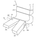
又、本発明においては、図55に示すように、大腿部あるいは大腿部とふくらはぎ部を載置する脚載せ台46が直動アクチュエータ390により駆動されて脚載せ台46の傾斜が調整可能とされていてもよい。脚載せ台46は左右の脚にそれぞれ対応して一対の脚載せプレ−ト347、349から成る。脚載せプレ−ト347、349はそれぞれ互いに独立に後端部の回動用軸353を軸心にして縦方向に揺動可能とされている。回動用軸353は横向きであり、大腿部の付け根近傍に位置する。脚載せプレ−ト347、349はそれぞれ回動アクチュエータ355、355により回動用軸353を介して駆動される。これにより、脚部のうっ血やむくみの解消、緩和に寄与する。脚載せ台46は大腿部の少なくとも膝がわを載置する。
In the present invention, as shown in FIG. 55, the
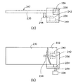
更に脚載せプレ−ト347、349は先端が脚の開閉状に開閉することが好ましい。図56に脚の開閉状に開閉する脚載せプレ−ト347(349)の機構の一例を示す。図56においては、脚載せプレ−ト347が、主プレート230と主プレート230の後端の後方に位置する副プレート232とに分割されて成る。副プレート232は連結部材234を介してL型基板236に固定され、回動アクチュエータ238により、回動アクチュエータ238の回動軸339、L型基板236を介して駆動され水平な回動軸339を軸心として回動する。これにより、脚載せプレ−ト347の先端が縦方向に揺動する。脚載せ台46は座部4(図6等)を構成する。
Furthermore, it is preferable that the
一方、他の回動アクチュエータ240が回動軸242を鉛直にしてL型基板236に固定され、主プレート230が、回動アクチュエータ240により、回動軸242、揺動アーム244を介して回動軸242を軸心として回動し、主プレート230は、先端が左右方向に揺動する。脚載せプレ−ト49の揺動構造を脚載せプレ−ト347のこの揺動構造と対照にすることにより、脚の開閉状に開閉する脚載せプレ−ト347、349の機構となる。
On the other hand, another
更に、本発明の椅子においては、腰椎支持盤12、骨盤受けユニット130座盤142が直動アクチュエータや手動のリンク機構により昇降可能とされて座面の高さが調整可能とされていてもよい。
Furthermore, in the chair of the present invention, the
又、椅子2においては、図57に示すように、背部支持盤12bに人型窪み402が形成されていてもよい。人型窪み402は着座した人の頭部から腰部にわたる背後の人体の形状に沿うような内壁面を有している。これにより、人型窪み402の内壁面が人の頭部から腰部にわたる背後にほぼ均等に接する。
Moreover, in the
人型窪み402は、例えば、人型に合わせた窪みを有する硬質フォームのようなクッション材をモールド成形して得ることが出来る。あるいは、背部支持盤12bの少なくとも表面部を低反発発泡ウレタン材で構成し、人の着座により、その低反発発泡ウレタン材が人によりスタンプされて人型に窪むことにより成形されてもよい。低反発発泡ウレタン材は除重により所定時間後には元の形状に回復するので、着座する人ごとに、その人の背部の体形の窪みがスタンプされて得られるので好ましい。
The human-
低反発発泡ウレタン材の代表的なものは、イソシアネートとポリオールの重合反応、及びイソシアネートと水が反応する泡化反応を主体にする化学反応を利用して製造され、ポリオールの構造が調整されてガラス転移点が常温になった低反発ウレタンフォームである。低反発発泡ウレタン材に代えて、ガラス転移点が常温になったポリエステル系、ポリオレフィン系等の樹脂の発泡体が用いられてもよい。 A typical low-rebound foamed urethane material is manufactured using a chemical reaction mainly composed of a polymerization reaction of isocyanate and polyol and a foaming reaction in which isocyanate and water react, and the structure of the polyol is adjusted to make glass. A low-resilience urethane foam with a transition point at room temperature. Instead of the low-rebound foamed urethane material, a resin foam such as a polyester or polyolefin resin having a glass transition point at room temperature may be used.
本発明の椅子のこれら記載の構成により、本発明の椅子は、座面や背もたれを人10の形状にフィットした形とし、すき間をなくし体圧分散させ体重を支える構造になっている。
With the above-described configurations of the chair of the present invention, the chair of the present invention has a structure in which the seat surface and the backrest are fitted to the shape of the
椅子2がレース用のカーシトとして用いられる場合は、上記態様に加え、ドライビング操作に干渉しない形で高速コーナリングや横G、衝突時などの横方向からの衝撃から体を守るため、公知のショルダー(肩)、ペルビス(骨盤)、ニー(膝)ガードシステムが付化されてもよい。
When the
更に、自由度が高く、衝撃の度合いによっては生命や高度の機能障害にかかわる頭頸部に関しては前後方向や横方向の衝撃のみならず、捻れや回転のかかった衝撃に対してもあたかもシュートやスライダーをキャッチするキャッチャーミットのように極度の捻れや回転から頭頸部を保護しながら頭頸部の衝撃を吸収し、頭頸部をガードするシステムが必要となる。すなわち衝突角度と頭頸部の姿勢によらず衝撃にともなう脳神経の損傷と頸椎の過伸展を防ぐシステムが求められる。 Furthermore, the degree of freedom is high, and depending on the degree of impact, the head and neck, which are related to life and high-level functional impairments, are not only anteroposterior and lateral impacts, but also shoots and sliders against twisted and rotated impacts. A system that protects the head and neck and protects the head and neck while protecting the head and neck from extreme twists and rotations, such as a catcher mitt that catches the head, is required. That is, there is a need for a system that prevents cranial nerve damage and excessive extension of the cervical spine due to impact regardless of the collision angle and head and neck posture.
頭頸部は胸郭により安定固定されている胸椎を基盤として上端に4〜5kgの頭蓋をのせ可動性に富む構造となっている。したがって急速な加速、減速運動が起こった場合頸部にもたらされる慣性のみならず揺り戻し現象にも対応できなければならない。後方からの追突の場合、頸部以下では急激な加速をみるのに対し、頸部にもたらされる慣性によって頸椎は急激な過伸展を余儀なくされる。次の瞬間に起きる車体の急停止による体幹への減速力が頸椎に加わって頸椎の過伸展の反動とともに急激な過屈曲が強制させられる。頭頸部損傷を招くこのむち打ちメカニズムは正面衝突の場合にもみられ、頸椎の過屈曲、それに続く反動で揺り戻しによる強制的な過伸展を余儀なくされる。これら過伸展のあとの過屈曲(後方からの追突)、過屈曲のあとの過伸展(正面衝突)や、高速コーナリングや横G、衝突時などの横方向からの衝撃に対応するために、本発明においては図58の斜視模式図及び図59の正面模式図に示す椅子2aが好適に用いられる。
The head and neck has a structure with high mobility by placing a 4-5 kg skull on the upper end based on the thoracic vertebra which is stably fixed by the rib cage. Therefore, when rapid acceleration / deceleration motion occurs, it must be able to cope with not only the inertia brought about by the neck but also the swingback phenomenon. In the case of a rear-end collision, the cervical spine is forced to rapidly overextend due to the inertia brought about by the cervix, while rapid acceleration is observed below the cervix. A deceleration force to the trunk due to the sudden stop of the vehicle body that occurs at the next moment is applied to the cervical spine, and a sudden hyperflexion is forced along with a reaction of the cervical spine overextension. This whiplash mechanism that causes head and neck damage is also seen in the case of a frontal collision, forcing the cervical spine to be overextended, followed by a forced overextension due to rocking. In order to cope with over-extension after rearrangement (rear-end collision from the rear), over-extension after over-flexion (frontal collision), and high-speed cornering, lateral G, impact from the lateral direction, such as during a collision, In the invention, the
椅子2aは、背部支持盤12bに、人10の肩の左右の各側面に当接又は近接して配されて肩の左右方向の動きを拘束する一対の肩部保護壁42が更に備えられている。これにより、高速コーナリングや横G、衝突時などの横方向からの衝撃から肩を守ることが出来る。なお、符号404は車のハンドルを示す。
The
又、背部支持盤12bに、人10の首14の頚椎棘突起部に相当する位置の左右の各側面に当接又は近接して、首14の左右方向の動きを拘束する一対の首部保護壁16が配されている。首部保護壁16の面は、略弧状又は略U字形に曲った首部保護壁部材(長尺曲り部材)18の曲りの内側の面から成る。首部保護壁部材18は自身の長手方向を水平にして首14を曲りの内側に位置させて背部支持盤12bに配されている。
Further, a pair of neck protection walls that restrain the movement of the
更に、背部支持盤12bには、首14の背後の頚椎棘突起部に相当する部分に当接又は近接して配されてその部分の後方への動きを拘束する頚椎棘突起部保護壁24が備えられている。頚椎棘突起部保護壁24は、首部保護壁部材18の曲りの内側(曲率中心がわ)の面の、首部保護壁部材18の長手方向にみた中央部から構成されている。
Further, the
又更に、背部支持盤12bには、人10の頭の左右の各側面に当接又は近接して配されて頭部30の左右方向の動きを拘束する一対の頭部保護壁32が備えられている。
Furthermore, the
これらにより、頭頸部に関しては前後方向や横方向の衝撃のみならず、捻れや回転のかかった衝撃に対してもあたかもシュートやスライダーをキャッチするキャッチャーミットのように極度の捻れや回転から頭頸部を保護しながら頭頸部の衝撃を吸収し、頭頸部をガードすることが出来る。すなわち衝突角度と頭頸部の姿勢によらず衝撃にともなう脳神経の損傷と頸椎の過伸展を防ぐことが出来る。 As a result, with regard to the head and neck, not only the impact in the front and rear direction and the lateral direction, but also the impact on the twist and rotation, the head and neck from the extreme twist and rotation like a catcher mitt that catches the chute and slider. While protecting, it can absorb the impact of the head and neck and guard the head and neck. That is, it is possible to prevent cranial nerve damage and excessive extension of the cervical spine due to impact regardless of the collision angle and the posture of the head and neck.
椅子2aにおける頭部保護壁32、首部保護壁部材18、肩部保護壁42のそれぞれの位置は可変であってもよい。例えば、頭部保護壁32用の頭部保護壁用部材333と首部保護壁部材18とを組み合わせた図60に示す保護壁エレメント302を移動させる、図61に示す移動装置300が、背もたれ盤に組み込まれてもよい。移動装置300には更に、肩部保護壁42用の一対の肩部保護壁用部材351を肩幅方向に移動させられる肩部保護壁移動エレメント333が組み込まれている。符号313は移動装置300のフレームである。
The positions of the
図60に示す保護壁エレメント302においては、頭部保護壁用部材333と首部保護壁部材18とが取り付け部材306を介して連結され、更に首部保護壁部材18が左右に配置された組み込み用ブロック312、312にまたがって水平に配された水平梁310の中央に固定されている。
In the
図47に示す間隔可変装置306kと同様の機構による肩部保護壁移動エレメント333p、及び保護壁エレメント302が図61に示す態様で移動装置300に組み込まれる。支持用アーム361p、362p(図47)に肩部保護壁用部材351、351が取り付けられている。移動装置300の最下部に位置する昇降用モータ361が正・逆回転する。このモータ361の回転はプーリ362、ベルト363を介して減速されて垂直な2本のねじ軸364,365に伝達される。肩部保護壁移動エレメント333pとねじ軸364,365とは、ねじ軸364、365にそれ螺入して上下移動するナット型ブラケット366、367を介して互いに連結されている。
A shoulder protective wall moving element 333p and a
符号373、374は腰椎支持盤12の内部に配されたガイドレールである。肩部保護壁移動エレメント333pは、軸受けボックス324及び駆動ボックス326の両側壁にそれぞれ上下2つずつ設けられたガイドローラ8bにより、ガイドレール373、374に装着されている。そして、肩部保護壁移動エレメント333pは、ねじ軸364、365の正・逆回転によりガイドレール373、374にガイドされて上下移動する。これにより、肩部保護壁用部材51、51も上下移動する。
組み込み用ブロック312、312が軸受けボックス324及び駆動ボックス326の上にそれぞれ載せられて固定され、保護壁エレメント302が肩部保護壁移動エレメント333pとともに上下動する。
The assembling blocks 312 and 312 are mounted and fixed on the
なお、本発明において椅子がカーシートとして使用される場合、揺り戻しによる強制的な過伸展や過屈曲に対処するためには、シートベルトの装着が必要であることはいうまでもない。 Needless to say, when a chair is used as a car seat in the present invention, it is necessary to attach a seat belt in order to cope with forced overextension or overbending caused by swinging back.
椅子2aに頭部保護壁32を設ける代わりに図62に示すように、人10がヘルメット400を装着して揺り戻しによる強制的な過伸展や過屈曲を防止してもよい。又、ヘルメットを装着しない場合、過屈曲に対しては図63に示すように、シートショルダ−エアバック502で対処することが更に好ましい。
Instead of providing the
又、椅子2aにおいても、図57に示すような窪み402が形成された背部支持盤12bが用いられてもよい。窪み402の内壁の側面が図22における頭部保護壁32及び肩部保護壁42に代えて、頭部保護壁及び肩部保護壁の機能をはたす。
Also in the
更に、本発明の椅子においては、ガイドレールや背もたれ盤6の回動部分を駆動する上述のモータ等のアクチュエータをはじめ、駆動装置70、保護壁エレメント302、肩部保護壁移動エレメント333、脚載せ台46、上部背もたれ盤370等の可動部分を駆動する上述のモータや直動アクチュエータ等のアクチュエータの群が制御システムを備える制御盤により集中管理されて、使用する人の体型や使い勝手に合わせて、可動部分が位置決めされてもよい。このような制御システムの一例を図64に示す。図64において、制御システム410は、各アクチュエータを駆動回路を介して駆動する主制御回路(制御部)と、各スイッチによる開閉指令を主制御回路に送るための副制御回路と、各可動部分の設定位置を入力する設定値入力回路(入力部)と、各回路に定電圧、電流を供給する定電圧回路、各スイッチの開閉を表示する表示ランプ点灯回路を含んで構成される。設定値入力回路は、入力された設定値に基き、主制御回路にデータを送り、このデータに基き各アクチュエータが駆動される。又、設定値入力回路には各人別の設定値も入力される。各人別の設定値は、入力データ記憶回路に記憶される。特定の人を指定して設定値入力回路に入力することにより、入力データ記憶回路を介して、その特定の人のデータに基き各アクチュエータが駆動され、各可動部分の位置がその人に適したものに設定される。
Furthermore, in the chair of the present invention, in addition to the actuator such as the motor described above that drives the rotating portion of the guide rail and the
図64に示す制御システム410を備えた本発明の椅子やカーシートを使用する場合、はじめに各人が自分の体型に合った形で各可動部分をセットアップし各人ごとにメモリーさせることでいつでも的確なポジションを設定できる。複数の人が使用する場合、複数のセットアップメモリーボタンから選択して特定のセットアップメモリーボタンを増やすことで、ボタン一つで的確なポジションを設定する態様であってもよい。
When using the chair or car seat of the present invention equipped with the
即ち、本発明の椅子は背もたれ盤6を回動させる回動手段A、骨盤部背面受け盤319を回動及び移動させる移動手段B、首部規制壁を移動させる移動手段C、頚椎棘突起部保護壁を移動させる移動手段D、頭部保護壁を移動させる移動手段E、脚載せ台を移動させる移動手段F、座部を移動させる移動手段F、背もたれ盤を移動させる移動手段G、幅規制ホルダを移動させる移動手段H、あるいはガイドレールを駆動する移動手段Iから選択される回動手段及び/又は移動手段がそれぞれ駆動用のアクチュエータと、該アクチュエータの作動量の値を入力する入力部と、該アクチュエータの作動を制御する制御部及び前記入力部に入力された使用する人や使用目的に対応するアクチュエータの作動量の値を記憶する記憶部とを備え、記憶された該値の中から指定された値に基き前記制御部を介して該アクチュエータが作動するように構成される態様であってもよい。
That is, the chair of the present invention has a rotating means A for rotating the
その他、本発明は、主旨を逸脱しない範囲で当業者の知識に基づき種々なる改良、修正、変更を加えた態様で実施できるものである。例えば本発明の椅子の随所に使用されるアクチュエータに代えて手動の回動機構あるいは進退機構が用いられてもよい。又、例えば本発明の椅子の着座する人と接する面を形成する部材がクッション材で被覆することがなされて当然である。更に、例えば本発明において用いられるアクチュエータは、流体圧力を伝達するシリンダ等の流体装置を介して駆動対象を駆動してもよい。ウオームギア、ラック・ピニオン等の歯車群を介して駆動対象を駆動してもよい。更に、座部4、後頭支持部1xx、頚椎支持部2xx、胸背支持部4xx、腰椎支持部5xx、骨盤支持部7xx及び臀部−大腿根元部支持部8xx等の支持部については、支持部の部材や各支持部間の連結の態様や連動の態様は、本明細書に記載された態様に限定されるものではなく、周知の各種の連動機構、連結機構を用いることが出来る。支持部の伸縮機構や曲げ機構も周知の各種の機構を用いることが出来る。支持部には必要に応じて周知の各種の可撓性板や伸縮性板を用いることが出来る。
In addition, the present invention can be carried out in a mode in which various improvements, modifications, and changes are added based on the knowledge of those skilled in the art without departing from the spirit of the present invention. For example, a manual rotation mechanism or advancing / retreating mechanism may be used instead of the actuators used in the chairs of the present invention. In addition, for example, a member that forms a surface in contact with a person on which the chair of the present invention is seated is naturally covered with a cushion material. Further, for example, the actuator used in the present invention may drive the driven object via a fluid device such as a cylinder that transmits fluid pressure. The drive target may be driven via a gear group such as a worm gear, a rack and a pinion. Further, for the support parts such as the
本発明の椅子は、家庭用、事務用の椅子や、カーシートのみならず、特殊重機用、特殊監視員用、精密作業用、航空機用等の肉体や神経を過度に緊張させる作業用に、その緊張を緩和し、疲労が蓄積しない椅子として好適に用いることが出来る。又、電動マッサージチェアの椅子の部分に好適に用いられる。 The chair of the present invention is not only for home and office chairs and car seats, but also for special heavy machinery, for special observers, for precision work, for aircraft, etc. It can be suitably used as a chair that relaxes the tension and does not accumulate fatigue. Moreover, it uses suitably for the part of the chair of an electric massage chair.
2、2a、2m、2x、2aa、2ny:椅子
4:座部
10:人
1xx:後頭支持部
2xx:頚椎支持部
4xx:胸背支持部
5xx、521:腰椎支持部
7xx:骨盤支持部
8xx:臀部−大腿根元部支持部
16:首部保護壁
24:頚椎棘突起部保護壁
32:頭部保護壁
42:肩部保護壁
46:脚載せ台
402:窪み
673:背・腰部規制壁
671:首部規制壁
72x、74x、59、137、161a、161b、238、240、355、390、614、614h、:アクチュエータ
804:胸背部受けシート
807:骨盤部受けシート
2, 2a, 2m, 2x, 2aa, 2ny: chair 4: seat 10: human 1xx: occipital support 2xx: cervical support 4xx: chest back support 5xx, 521: lumbar support 7xx: pelvic support 8xx: Saddle-thigh root support 16: neck protection wall 24: cervical spine projection protection wall 32: head protection wall 42: shoulder protection wall 46: leg rest 402: depression 673: back / lumbar regulation wall 671:
Claims (26)
各該アクチュエータの作動量に対応の値を入力する入力部、
各該アクチュエータの作動を制御する制御部、
各該アクチュエータを駆動する駆動回路、
各該値を入力する入力部、及び前記入力部に入力された使用する人や使用目的に対応する前記値を記憶する記憶部
を備え、記憶された該値の中から指定された値に基き前記制御部、前記駆動回路を介して前記アクチュエータが作動する請求項1乃至25のいずれかに記載の椅子。
A seat that supports the thigh of the person who sits down, a cervical support that supports the cervical spine, a chest back support that supports the back of the chest, a lumbar support that supports the lumbar, a pelvic support that supports the pelvis, a hip and a thigh An actuator that directly or indirectly drives a base selected from a buttock-thigh root support portion that supports the base of the thigh,
An input unit for inputting a value corresponding to the operation amount of each actuator;
A control unit for controlling the operation of each actuator;
A drive circuit for driving each actuator;
An input unit for inputting each value, and a storage unit for storing the value corresponding to the user or purpose of use input to the input unit, and based on a value designated from the stored values The chair according to any one of claims 1 to 25, wherein the actuator is operated via the control unit and the drive circuit.
Priority Applications (1)
| Application Number | Priority Date | Filing Date | Title |
|---|---|---|---|
| JP2004260510A JP4721254B2 (en) | 2004-09-08 | 2004-09-08 | Chair |
Applications Claiming Priority (1)
| Application Number | Priority Date | Filing Date | Title |
|---|---|---|---|
| JP2004260510A JP4721254B2 (en) | 2004-09-08 | 2004-09-08 | Chair |
Publications (2)
| Publication Number | Publication Date |
|---|---|
| JP2006075257A true JP2006075257A (en) | 2006-03-23 |
| JP4721254B2 JP4721254B2 (en) | 2011-07-13 |
Family
ID=36155206
Family Applications (1)
| Application Number | Title | Priority Date | Filing Date |
|---|---|---|---|
| JP2004260510A Active JP4721254B2 (en) | 2004-09-08 | 2004-09-08 | Chair |
Country Status (1)
| Country | Link |
|---|---|
| JP (1) | JP4721254B2 (en) |
Cited By (7)
| Publication number | Priority date | Publication date | Assignee | Title |
|---|---|---|---|---|
| WO2007111213A1 (en) * | 2006-03-28 | 2007-10-04 | Matsushita Electric Works, Ltd. | Massage chair |
| JP2007307347A (en) * | 2006-04-20 | 2007-11-29 | Assist:Kk | Seating apparatus for leading to natural sitting posture |
| JP2008168667A (en) * | 2007-01-09 | 2008-07-24 | Toyota Motor Corp | Seat device for vehicle |
| JP2014525303A (en) * | 2011-09-03 | 2014-09-29 | ティ キム ローン パム | Orthodontic chair for preventing and treating spinal and spinal disorders |
| US9131777B2 (en) | 2013-10-25 | 2015-09-15 | Toyota Motor Engineering & Manufacturing North America, Inc. | Variable lumbar support assembly |
| CN113116690A (en) * | 2021-04-25 | 2021-07-16 | 哈尔滨耀一堂健康科技有限公司 | Massage chair |
| KR102355901B1 (en) * | 2021-03-08 | 2022-02-08 | 최종수 | Bed for inducing nasal breathing during sleep |
Families Citing this family (2)
| Publication number | Priority date | Publication date | Assignee | Title |
|---|---|---|---|---|
| KR101537195B1 (en) * | 2014-10-23 | 2015-07-15 | 김문석 | Multifunctional chair for spinal traction |
| NL2028153B1 (en) * | 2021-05-05 | 2022-11-23 | Life & Mobility Dev B V | Backrest and chair |
Citations (8)
| Publication number | Priority date | Publication date | Assignee | Title |
|---|---|---|---|---|
| JPS55158946U (en) * | 1979-05-01 | 1980-11-15 | ||
| JPH03237903A (en) * | 1990-02-16 | 1991-10-23 | Mitsubishi Electric Corp | Oa chair |
| JPH0686720A (en) * | 1992-07-17 | 1994-03-29 | Itoki Crebio Corp | Chair |
| JPH06133828A (en) * | 1992-10-21 | 1994-05-17 | Itooki:Kk | Supporting method of seated person on chair by back rest and chair using this supporting method |
| JPH08117051A (en) * | 1994-10-27 | 1996-05-14 | Eba:Kk | Vehicle seat |
| JPH11508209A (en) * | 1995-06-26 | 1999-07-21 | ピー デラーノ ローランド | Whiplash prevention device |
| JP2001517514A (en) * | 1997-09-30 | 2001-10-09 | デュール シート テクノロジーズ インコーポレイテッド | Chair with two movable seats |
| JP2002125794A (en) * | 2000-10-23 | 2002-05-08 | Mika Sekine | Device to prevent head from swaying |
-
2004
- 2004-09-08 JP JP2004260510A patent/JP4721254B2/en active Active
Patent Citations (8)
| Publication number | Priority date | Publication date | Assignee | Title |
|---|---|---|---|---|
| JPS55158946U (en) * | 1979-05-01 | 1980-11-15 | ||
| JPH03237903A (en) * | 1990-02-16 | 1991-10-23 | Mitsubishi Electric Corp | Oa chair |
| JPH0686720A (en) * | 1992-07-17 | 1994-03-29 | Itoki Crebio Corp | Chair |
| JPH06133828A (en) * | 1992-10-21 | 1994-05-17 | Itooki:Kk | Supporting method of seated person on chair by back rest and chair using this supporting method |
| JPH08117051A (en) * | 1994-10-27 | 1996-05-14 | Eba:Kk | Vehicle seat |
| JPH11508209A (en) * | 1995-06-26 | 1999-07-21 | ピー デラーノ ローランド | Whiplash prevention device |
| JP2001517514A (en) * | 1997-09-30 | 2001-10-09 | デュール シート テクノロジーズ インコーポレイテッド | Chair with two movable seats |
| JP2002125794A (en) * | 2000-10-23 | 2002-05-08 | Mika Sekine | Device to prevent head from swaying |
Cited By (9)
| Publication number | Priority date | Publication date | Assignee | Title |
|---|---|---|---|---|
| WO2007111213A1 (en) * | 2006-03-28 | 2007-10-04 | Matsushita Electric Works, Ltd. | Massage chair |
| JP2007260176A (en) * | 2006-03-28 | 2007-10-11 | Matsushita Electric Works Ltd | Massager |
| JP4670702B2 (en) * | 2006-03-28 | 2011-04-13 | パナソニック電工株式会社 | Massage machine |
| JP2007307347A (en) * | 2006-04-20 | 2007-11-29 | Assist:Kk | Seating apparatus for leading to natural sitting posture |
| JP2008168667A (en) * | 2007-01-09 | 2008-07-24 | Toyota Motor Corp | Seat device for vehicle |
| JP2014525303A (en) * | 2011-09-03 | 2014-09-29 | ティ キム ローン パム | Orthodontic chair for preventing and treating spinal and spinal disorders |
| US9131777B2 (en) | 2013-10-25 | 2015-09-15 | Toyota Motor Engineering & Manufacturing North America, Inc. | Variable lumbar support assembly |
| KR102355901B1 (en) * | 2021-03-08 | 2022-02-08 | 최종수 | Bed for inducing nasal breathing during sleep |
| CN113116690A (en) * | 2021-04-25 | 2021-07-16 | 哈尔滨耀一堂健康科技有限公司 | Massage chair |
Also Published As
| Publication number | Publication date |
|---|---|
| JP4721254B2 (en) | 2011-07-13 |
Similar Documents
| Publication | Publication Date | Title |
|---|---|---|
| KR101028369B1 (en) | A Adjustable Chair for the Spine | |
| CN103251491B (en) | Limit, relocate, draw and telecontrol equipment and method | |
| KR102124863B1 (en) | Adaptive traction apparatus with human spine curvature and the method for traction human spine using the same | |
| JPH0274429A (en) | Seat for automobile | |
| CN101287426A (en) | Recliner spinal traction device | |
| JP4721254B2 (en) | Chair | |
| CN107920667A (en) | Back support | |
| JP2006521905A (en) | Seat with adjustable support system | |
| JP2008178491A (en) | Massage chair | |
| CN110074928B (en) | Medical care mattress | |
| KR101725227B1 (en) | Apparatus for spine traction and support | |
| KR100739020B1 (en) | Lumber traction apparatus | |
| WO2007027573A2 (en) | Lumbar lordosis brace | |
| KR102098904B1 (en) | Sitting posture correction chair | |
| JP2005530530A (en) | Furniture with massage unit | |
| JP4511326B2 (en) | Chair backrest structure | |
| KR101647439B1 (en) | Cushion forming curvature of cervical vertebra and thoracic vertebra | |
| JP5584746B2 (en) | Chair focused on pelvic rotation | |
| CN113350002B (en) | Spinal medical device | |
| EP3716815A1 (en) | Rehabilitation device | |
| US11484461B2 (en) | Chair-type massager | |
| JP6934088B2 (en) | Chair type massage machine | |
| CN210990992U (en) | Lumbar vertebra traction device driven by pneumatic muscles | |
| JP2014076129A5 (en) | Chair focused on pelvic rotation | |
| KR102253084B1 (en) | Correction device of turtle neck for backrest mounted type |
Legal Events
| Date | Code | Title | Description |
|---|---|---|---|
| A711 | Notification of change in applicant |
Free format text: JAPANESE INTERMEDIATE CODE: A711 Effective date: 20070906 |
|
| A621 | Written request for application examination |
Free format text: JAPANESE INTERMEDIATE CODE: A621 Effective date: 20070907 |
|
| A521 | Request for written amendment filed |
Free format text: JAPANESE INTERMEDIATE CODE: A821 Effective date: 20070910 |
|
| A977 | Report on retrieval |
Free format text: JAPANESE INTERMEDIATE CODE: A971007 Effective date: 20100913 |
|
| A131 | Notification of reasons for refusal |
Free format text: JAPANESE INTERMEDIATE CODE: A131 Effective date: 20100916 |
|
| A521 | Request for written amendment filed |
Free format text: JAPANESE INTERMEDIATE CODE: A523 Effective date: 20101115 |
|
| TRDD | Decision of grant or rejection written | ||
| A01 | Written decision to grant a patent or to grant a registration (utility model) |
Free format text: JAPANESE INTERMEDIATE CODE: A01 Effective date: 20110301 |
|
| A61 | First payment of annual fees (during grant procedure) |
Free format text: JAPANESE INTERMEDIATE CODE: A61 Effective date: 20110331 |
|
| FPAY | Renewal fee payment (event date is renewal date of database) |
Free format text: PAYMENT UNTIL: 20140415 Year of fee payment: 3 |
|
| R150 | Certificate of patent or registration of utility model |
Ref document number: 4721254 Country of ref document: JP Free format text: JAPANESE INTERMEDIATE CODE: R150 Free format text: JAPANESE INTERMEDIATE CODE: R150 |
|
| R250 | Receipt of annual fees |
Free format text: JAPANESE INTERMEDIATE CODE: R250 |
|
| R250 | Receipt of annual fees |
Free format text: JAPANESE INTERMEDIATE CODE: R250 |
|
| R250 | Receipt of annual fees |
Free format text: JAPANESE INTERMEDIATE CODE: R250 |
|
| R250 | Receipt of annual fees |
Free format text: JAPANESE INTERMEDIATE CODE: R250 |
|
| R250 | Receipt of annual fees |
Free format text: JAPANESE INTERMEDIATE CODE: R250 |
|
| R250 | Receipt of annual fees |
Free format text: JAPANESE INTERMEDIATE CODE: R250 |
|
| R250 | Receipt of annual fees |
Free format text: JAPANESE INTERMEDIATE CODE: R250 |
|
| R250 | Receipt of annual fees |
Free format text: JAPANESE INTERMEDIATE CODE: R250 |
|
| R250 | Receipt of annual fees |
Free format text: JAPANESE INTERMEDIATE CODE: R250 |
|
| R250 | Receipt of annual fees |
Free format text: JAPANESE INTERMEDIATE CODE: R250 |
|
| R250 | Receipt of annual fees |
Free format text: JAPANESE INTERMEDIATE CODE: R250 |