JP2006064180A - Vehicular rolling bearing unit with encoder - Google Patents
Vehicular rolling bearing unit with encoder Download PDFInfo
- Publication number
- JP2006064180A JP2006064180A JP2005250941A JP2005250941A JP2006064180A JP 2006064180 A JP2006064180 A JP 2006064180A JP 2005250941 A JP2005250941 A JP 2005250941A JP 2005250941 A JP2005250941 A JP 2005250941A JP 2006064180 A JP2006064180 A JP 2006064180A
- Authority
- JP
- Japan
- Prior art keywords
- encoder
- peripheral surface
- ring
- slinger
- rotating
- Prior art date
- Legal status (The legal status is an assumption and is not a legal conclusion. Google has not performed a legal analysis and makes no representation as to the accuracy of the status listed.)
- Pending
Links
Images


Abstract
Description
この発明に係る自動車用エンコーダ付転がり軸受ユニットは、自動車の車輪を懸架装置に対し回転自在に支持すると共に、この転がり軸受ユニットにより支持された車輪の回転速度を検出する為に利用する。 The rolling bearing unit with an encoder for an automobile according to the present invention supports the wheel of the automobile so as to be rotatable with respect to the suspension device and detects the rotational speed of the wheel supported by the rolling bearing unit.
自動車の車輪を懸架装置に対して回転自在に支持すると共に、アンチロックブレーキシステム(ABS)やトラクションコントロールシステム(TCS)を制御すべく、この車輪の回転速度を検出する為に、従来から各種構造のエンコーダ付転がり軸受ユニットが知られている。又、この様なエンコーダ付転がり軸受ユニットに組み込むエンコーダとして、S極とN極とを円周方向に亙って交互に且つ等間隔で配置した、ゴム磁石、プラスチック磁石等の永久磁石を使用するものが、車輪の回転速度に関係なくセンサの出力を安定させられる事から、一部で使用されている。更に、この様な永久磁石製のエンコーダを使用する場合に、このエンコーダを非磁性材製の支持素子に支持固定し、この支持素子により周囲空間から隔てる構造も、特許文献1に記載されている様に、従来から知られている。
In order to detect the rotational speed of this wheel in order to support the wheel of the automobile so that it can rotate freely with respect to the suspension system and to control the anti-lock brake system (ABS) and traction control system (TCS), various structures have been conventionally used. A rolling bearing unit with an encoder is known. Moreover, as an encoder incorporated in such a roller bearing unit with an encoder, permanent magnets such as rubber magnets and plastic magnets, in which S poles and N poles are alternately arranged at equal intervals in the circumferential direction, are used. Some are used because they can stabilize the output of the sensor regardless of the rotational speed of the wheels. Furthermore, when using such an encoder made of a permanent magnet, a structure in which the encoder is supported and fixed to a support element made of a non-magnetic material and separated from the surrounding space by this support element is also described in
図8は、この特許文献1に記載されたエンコーダ付転がり軸受ユニットを示している。このエンコーダ付転がり軸受ユニットは、一般的な転がり軸受ユニットと同様に、その外周面に内輪軌道1を有し、使用時に車輪と共に回転する内輪2と、その内周面に外輪軌道3(図8には図示せず。図1〜7参照。)を有し、使用時に懸架装置に支持された状態で回転しない外輪4と、この外輪軌道3と上記内輪軌道1との間に転動自在に設けられた複数個の転動体5とを備える。そして、上記内輪2の端部外周面と上記外輪4の端部内周面との間を塞ぐ組み合わせシールリング6に、エンコーダ7を組み込んでいる。
FIG. 8 shows a rolling bearing unit with an encoder described in
このうちの組み合わせシールリング6は、上記内輪2の端部外周面に外嵌固定した非磁性金属板製のスリンガ8と、上記外輪4の内周面に内嵌固定したシールリング9とから成る。又、このシールリング9は、断面L字形で円環状の芯金10の内周縁部に弾性材製のシールリップ11を、全周に亙り添設している。そして、このシールリップ11の内周縁を上記スリンガ8を構成する円筒部12の外周面に、このシールリップ11に外嵌したガータスプリング13の弾力により押し付けている。一方、上記スリンガ8を構成する円輪部14の軸方向両側面のうち、上記シールリング9に対向する内側面には、上記エンコーダ7を、全周に亙り添設している。このエンコーダ7は、永久磁石で、軸方向側面にS極とN極とを、交互に配置している。
The
上述の様なエンコーダ付転がり軸受ユニットは、上記内輪2を挿通した車軸の端部に車輪を支持固定すると共に、上記外輪4を懸架装置に支持固定する事により、この懸架装置に対して上記車輪を回転自在に支持する。又、この懸架装置に支持したセンサ15の検出部を、上記エンコーダ7の側面に対向させる。この状態で上記車輪と共に上記内輪2が回転すると、このエンコーダ7が上記スリンガ8と共に回転し、このエンコーダ7の側面と対向した上記センサ15の出力が変化する。このセンサ15の出力が変化する周波数は、車輪の回転速度に比例する。従って、センサ15の出力信号を図示しない制御器に入力すれば、上記車輪の回転速度を求め、ABSやTCSを適切に制御できる。
The above-mentioned rolling bearing unit with an encoder supports and fixes a wheel to an end of an axle through which the
又、上述の様に構成し作用する従来のエンコーダ付転がり軸受ユニットの場合には、永久磁石製のエンコーダ7が非磁性金属板製のスリンガ8により覆われて、外部空間に露出していない。この為、この外部空間に浮遊する磁性粉末が上記エンコーダ7に付着しにくく、仮に付着した場合でも、上記スリンガ8の回転に伴って周囲に振り飛ばされ、上記磁性粉末がそのまま上記エンコーダ7とセンサ15の検出部との間に残留しにくい。この為、このセンサ15による回転速度検出の精度確保を図れる。又、上記エンコーダ7に、小石等の異物が直接ぶつかる事もない為、このエンコーダ7に割れや欠け等の損傷が生じる事を防止して、このエンコーダ7を含んで構成する回転速度検出装置の信頼性確保を図れる。
In the case of a conventional rolling bearing unit with an encoder configured and operated as described above, the encoder 7 made of permanent magnet is covered with the slinger 8 made of nonmagnetic metal plate and is not exposed to the external space. For this reason, the magnetic powder floating in this external space is difficult to adhere to the encoder 7, and even if it adheres, the magnetic powder is swung away with the rotation of the slinger 8, and the magnetic powder is directly applied to the encoder 7 and the sensor. It is hard to remain between 15 detection units. For this reason, it is possible to ensure the accuracy of rotation speed detection by the
上述の様な、従来から知られているエンコーダ付転がり軸受ユニットの場合には、設計の自由度が小さく、例えば組み合わせシールリングのシール性向上、小型・軽量化、エンコーダ及びセンサの取付位置の変更等に対応できない。 In the case of a conventionally known rolling bearing unit with an encoder as described above, the degree of freedom in design is small, for example, improved sealing performance of a combination seal ring, miniaturization and weight reduction, and change of encoder and sensor mounting positions. It cannot correspond to etc.
本発明は、上述の様な事情に鑑み、必要に応じて、組み合わせシールリングのシール性向上、小型・軽量化、エンコーダ及びセンサの取付位置の変更等に対応できるエンコーダ付転がり軸受ユニットを実現すべく発明したものである。 In view of the circumstances as described above, the present invention realizes a rolling bearing unit with an encoder that can cope with improvement in sealing performance of a combined seal ring, reduction in size and weight, change in the mounting position of an encoder and a sensor, and the like as necessary. Invented accordingly.
本発明の自動車用エンコーダ付転がり軸受ユニットのうち、請求項1に記載したエンコーダ付転がり軸受ユニットは、静止輪と、回転輪と、複数個の転動体と、スリンガと、シールリングと、エンコーダと、カバー層とを備える。
このうちの静止輪は、静止側周面に静止側軌道を有し、使用時に懸架装置に支持された状態で回転しない。又、上記回転輪は、上記静止側周面と対向する回転側周面に回転側軌道を有し、使用時に車輪と共に回転する。又、上記複数個の転動体は、この回転側軌道と上記静止側軌道との間に転動自在に設けられている。又、上記スリンガは、円筒部とこの円筒部の端縁から径方向に折れ曲がった円輪部とを備える断面L字形で、このうちの円筒部を上記回転側周面の端部に嵌合する事により上記回転輪に対し、この回転輪と同心に支持固定されている。又、上記シールリングは、複数本のシールリップを備える円環状の弾性材を円環状の芯金により補強して成り、この芯金を上記静止側周面の端部に嵌合固定した状態で上記各シールリップの先端縁を上記スリンガを構成する円筒部の周面及び円輪部の片側面に摺接させている。又、上記エンコーダは、上記スリンガを構成する上記円輪部の他側面にその軸方向片側面を密着させる事により、全周に亙って上記回転輪と同心に固定されたもので、その軸方向他側面にS極とN極とを円周方向に亙って交互に配置している。更に、上記カバー層は、上記エンコーダの表面のうちの、少なくとも上記軸方向他側面を覆うものであり、非磁性材製である。
Among the rolling bearing units with an encoder of the present invention, the rolling bearing unit with an encoder according to
Among these, the stationary wheel has a stationary-side track on the stationary-side peripheral surface, and does not rotate while being supported by the suspension device during use. The rotating wheel has a rotating side track on the rotating side peripheral surface facing the stationary side peripheral surface, and rotates together with the wheel when in use. The plurality of rolling elements are provided between the rotating side track and the stationary side track so as to freely roll. The slinger has an L-shaped cross section including a cylindrical portion and an annular portion bent in a radial direction from an edge of the cylindrical portion, and the cylindrical portion is fitted to the end portion of the rotating side circumferential surface. Thus, the rotating wheel is supported and fixed concentrically with the rotating wheel. The seal ring is formed by reinforcing an annular elastic member having a plurality of seal lips with an annular cored bar, and the cored bar is fitted and fixed to the end of the stationary peripheral surface. The leading edge of each seal lip is brought into sliding contact with the peripheral surface of the cylindrical portion and the one side surface of the annular portion constituting the slinger. The encoder is fixed concentrically with the rotating wheel over the entire circumference by closely contacting one side surface in the axial direction to the other side surface of the circular ring portion constituting the slinger. S poles and N poles are alternately arranged on the other side surface in the circumferential direction. Further, the cover layer covers at least the other axial side surface of the encoder surface, and is made of a non-magnetic material.
又、請求項2に記載したエンコーダ付転がり軸受ユニットは、内輪と、外輪と、複数個の転動体と、エンコーダと、カバー層とを備える。このうちの内輪は、外周面に内輪軌道を有し、使用時に懸架装置に支持された状態で回転しない。又、上記外輪は、内周面に外輪軌道を有し、使用時に車輪と共に回転する。又、上記複数個の転動体は、この外輪軌道と上記内輪軌道との間に転動自在に設けられている。又、上記エンコーダは、上記外輪の外周面に外嵌固定されたもので、その外周面にS極とN極とを円周方向に亙って交互に配置している。更に、上記カバー層は、上記エンコーダの表面のうちの、少なくとも上記外周面を覆うもので、非磁性材製である。 A rolling bearing unit with an encoder according to a second aspect includes an inner ring, an outer ring, a plurality of rolling elements, an encoder, and a cover layer. Among these, the inner ring has an inner ring raceway on the outer peripheral surface, and does not rotate while being supported by the suspension device during use. The outer ring has an outer ring raceway on the inner peripheral surface, and rotates with the wheel when in use. The plurality of rolling elements are provided between the outer ring raceway and the inner ring raceway so as to roll freely. The encoder is fitted and fixed to the outer peripheral surface of the outer ring, and the S pole and the N pole are alternately arranged on the outer peripheral surface in the circumferential direction. Further, the cover layer covers at least the outer peripheral surface of the surface of the encoder, and is made of a nonmagnetic material.
上述の様に構成する本発明のエンコーダ付転がり軸受ユニットによれば、必要に応じて、組み合わせシールリングのシール性向上、小型・軽量化、エンコーダ及びセンサの取付位置の変更等に対応できるエンコーダ付転がり軸受ユニットを実現できて、自動車設計の自由度向上に寄与できる。
先ず、請求項1に記載したエンコーダ付転がり軸受ユニットによれば、エンコーダをスリンガを構成する円輪部の他側面に設けている為、この円輪部の径を特に大きくしなくても、シールリングを構成する複数本のシールリップのうちの一部を、上記円輪部の片側面に摺接させる事ができる。従って、スリンガとシールリングとから成る組み合わせシールリングのシール性向上を、特にこの組み合わせシールリングを大型化する事なく図れる。 又、請求項2に記載したエンコーダ付転がり軸受ユニットによれば、内輪の周囲で回転する外輪の外周面にエンコーダを外嵌固定し、このエンコーダの外周面にセンサの検出部を径方向に対向させる構造で、永久磁石製のエンコーダの保護を図れる。
According to the rolling bearing unit with an encoder of the present invention configured as described above, an encoder with an encoder that can cope with improvement in sealing performance of the combined seal ring, reduction in size and weight, change in the mounting position of the encoder and sensor, etc., as necessary. A rolling bearing unit can be realized, which can contribute to the improvement of the degree of freedom in automobile design.
First, according to the rolling bearing unit with an encoder described in
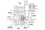
図1は、請求項1に対応する、本発明の実施例1を示している。本実施例のエンコーダ付転がり軸受ユニットは、一般的な転がり軸受ユニットと同様に、その外周面に内輪軌道1を有し、使用時に車輪と共に回転する内輪2と、その内周面に外輪軌道3を有し、使用時に懸架装置に支持された状態で回転しない外輪4aと、この外輪軌道3と上記内輪軌道1との間に転動自在に設けられた複数個の転動体5とを備える。そして、上記内輪2の端部外周面と上記外輪4aの端部内周面との間を塞ぐ組み合わせシールリング6aに、エンコーダ7aを組み込んでいる。
FIG. 1 shows a first embodiment of the present invention corresponding to claim 1. The rolling bearing unit with an encoder of this embodiment has an
このうちの組み合わせシールリング6aは、上記内輪2の端部外周面に外嵌固定した、強磁性ステンレス鋼板、鋼板等の、強磁性金属板製のスリンガ8aと、上記外輪4aの内周面に内嵌固定したシールリング9aとから成る。又、このシールリング9aは、断面L字形で円環状の芯金10の内周縁部に、複数本(図示の例では2本)のシールリップ16a、16bを有する弾性材17を、全周に亙って添設している。そして、これら両シールリップ16a、16bのうち、径方向内方に突出したシールリップ16aの先端縁(内周縁)を上記スリンガ8aを構成する円筒部12の外周面に、同じく軸方向側方に突出したシールリップ16bの先端縁を上記スリンガ8aを構成する円輪部14の内側面(転動体5を設置した空間18側の側面)に、それぞれシールリップ16a、16b自身の弾性により、全周に亙り弾性的に当接させている。従って、上記空間18の内外は、上記2本のシールリップ16a、16bにより二重にシールされて、この空間18内に封入したグリースが外部に漏洩する事、並びに外部空間に存在する雨水等の異物が上記空間18内に侵入する事を、有効に防止できる。
Of these, the
一方、上記スリンガ8aを構成する円輪部14の外側面には、上記エンコーダ7aを、全周に亙って添設している。このエンコーダ7aは、ゴム磁石、プラスチック磁石、フェライト磁石等の永久磁石で、軸方向(図1の左右方向)に着磁している。着磁方向は、円周方向に関して交互に且つ等間隔で変化させている。従って上記エンコーダ7aの外側面(上記空間18と反対側の側面)には、S極とN極とが円周方向に亙って交互に配置されている。更に、上記エンコーダ7aの外側面には、合成樹脂、アルミニウム、非磁性ステンレス等の非磁性材により、内外径を上記エンコーダ7aと同寸の円輪状に形成したカバープレート19を、接着等により添着して、請求項1に記載したカバー層を構成している。
On the other hand, the
上述の様な本実施例のエンコーダ付転がり軸受ユニットは、前記内輪2を挿通した(この内輪2をその端部に外嵌固定した)、図示しない車軸の端部に図示しない車輪を支持固定すると共に、前記外輪4aを、懸架装置を構成するナックル20の取付孔21に支持固定する。この構成により、この懸架装置に対して上記車輪を回転自在に支持する。又、上記ナックル20に設けた挿通孔22に外径側から内径側に挿通したセンサ15aの検出部を、上記エンコーダ7aの外側面に、上記カバープレート19を介して対向させている。この状態で上記センサ15aは、その基端部に設けた取付フランジ23を上記ナックル20の外周面に、ねじ24により結合する事で、このナックル20に対し固定している。
The rolling bearing unit with an encoder of the present embodiment as described above is inserted through the inner ring 2 (the
この様に構成各部材を組み立てた状態で、上記車輪と共に上記内輪2が回転すると、上記エンコーダ7aが前記スリンガ8aと共に回転し、このエンコーダ7aの外側面と対向した上記センサ15aの出力が変化する。このセンサ15aの出力が変化する周波数は、車輪の回転速度に比例する。従って、センサ15aの出力信号を図示しない制御器に入力すれば、上記車輪の回転速度を求め、ABSやTCSを適切に制御できる。
When the
又、上述の様に構成し作用する本実施例のエンコーダ付転がり軸受ユニットの場合は、永久磁石製のエンコーダ7aが非磁性板製のカバープレート19により覆われて、外部空間に露出していない。従って、この外部空間に浮遊する磁性粉末が上記エンコーダ7aの外側面に付着しにくく、仮に付着した場合でも、上記スリンガ8aと共に回転する上記カバープレート19の回転に伴って周囲に振り飛ばされ、上記磁性粉末がそのまま上記エンコーダ7aの外側面とセンサ15aの検出部との間に残留しにくい。この為、このセンサ15aによる回転速度検出の精度確保を図れる。又、上記エンコーダ7aに、小石等の異物が直接ぶつかる事もない為、このエンコーダ7aに割れや欠け等の損傷が生じる事を防止して、このエンコーダ7aを含んで構成する回転速度検出装置の信頼性確保を図れる。
Further, in the case of the rolling bearing unit with an encoder of this embodiment configured and acting as described above, the
更に、本実施例のエンコーダ付転がり軸受ユニットの場合には、上記エンコーダ7aを上記スリンガ8aを構成する円輪部14の外側面に設けている為、この円輪部14の径を特に大きくしなくても、前記シールリング9aを構成する複数本のシールリップ16a、16bのうちの軸方向側方に突出しているシールリップ16bの先端縁を、上記円輪部14の内側面に摺接させる事ができる。従って、上記スリンガ8aとシールリング9aとから成る組み合わせシールリング6aのシール性向上を、特にこの組み合わせシールリング6aを大型化(大径化)する事なく図れる。
Further, in the case of the rolling bearing unit with an encoder of the present embodiment, the
これに対して前述の図8に示した従来構造の場合には、シールリップの数を増やしてシール性向上を図ろうとした場合には、エンコーダ7を円輪部14の径方向外方に移動させるべく、この円輪部14の外径を大きくする必要が生じ、組み合わせシールリング6を大型化する必要が生じる。上記従来構造の場合には、ガータスプリング13を設ける事でシール性の確保を図っているが、その分、組み立て作業が面倒になるだけでなく、転がり軸受ユニットの回転抵抗も大きくなってしまう。本実施例のエンコーダ付転がり軸受ユニットの場合には、この様な従来構造の有する不都合をなくせる。
On the other hand, in the case of the conventional structure shown in FIG. 8, when the number of seal lips is increased to improve the sealing performance, the encoder 7 is moved radially outward of the
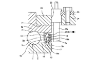
次に、図2は、やはり請求項1に対応する、本発明の実施例2を示している。本実施例の場合には、組み合わせシールリング6aを構成するスリンガ8aの外側面に添設するエンコーダ7aに、ゴム、合成樹脂等の非磁性材製のカバー層25をモールドして、このエンコーダ7aの外側面並びに内外両周縁を覆っている。その他の部分の構成及び作用は、上述した実施例1の場合と同様であるから、同等部分には同一符号を付して、重複する説明を省略する。
Next, FIG. 2 shows a second embodiment of the present invention, which also corresponds to claim 1. In the case of this embodiment, a cover layer 25 made of a nonmagnetic material such as rubber or synthetic resin is molded on the
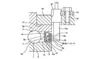
次に、図3は、やはり請求項1に対応する、本発明の実施例3を示している。本実施例の場合には、内輪2の端部外周面に、合成樹脂、アルミニウム、非磁性ステンレス鋼、真鍮の如き銅系合金等の非磁性板により、断面L字形で全体を円環状に形成したカバープレート26を外嵌固定している。そして、組み合わせシールリング6aを構成するスリンガ8aの円筒部12を上記カバープレート26を構成する円筒部27に外嵌固定すると共に、このカバープレート26を構成する円輪部28により、上記スリンガ8aを構成する円輪部14の外側面に添設したエンコーダ7aの外側面を覆っている。その他の部分の構成及び作用は、前述した実施例1例及び上述した実施例2の場合と同様であるから、同等部分には同一符号を付して、重複する説明を省略する。
Next, FIG. 3 shows
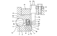
次に、図4は、やはり請求項1に対応する、本発明の実施例4を示している。本実施例の場合も上述した実施例2の場合と同様に、内輪2の端部外周面に、合成樹脂、アルミニウム、非磁性ステンレス鋼、真鍮の如き銅系合金等の非磁性板により、断面L字形で全体を円環状に形成したカバープレート26aを外嵌固定している。但し、本実施例の場合には、このカバープレート26aを構成する円筒部27aを、組み合わせシールリング6aを構成するスリンガ8aの円筒部12よりも軸方向端部寄り部分で、上記内輪2に外嵌固定している。そして、上記カバープレート26aを構成する円輪部28により、上記スリンガ8aを構成する円輪部14の外側面に添設したエンコーダ7aの外側面を覆っている。その他の部分の構成及び作用は、上述した実施例3の場合と同様であるから、同等部分には同一符号を付して、重複する説明を省略する。
Next, FIG. 4 shows Embodiment 4 of the present invention, which also corresponds to claim 1. In the case of this embodiment, as in the case of the above-described
次に、図5は、請求項2に対応する、本発明の実施例5を示している。本実施例の場合には、外輪4の外周面に円筒状のエンコーダ7bを、保持筒29を介して外嵌固定している。このうちの保持筒29は、磁性ステンレス鋼、軟鋼等の強磁性金属板により円筒状に構成されたもので、上記外輪4の端部外周面に、締り嵌めにより外嵌固定している。又、上記エンコーダ7bは、ゴム磁石、プラスチック磁石等の、若干の弾性変形自在な永久磁石で、径方向に着磁されている。着磁方向は円周方向に亙って交互に且つ等間隔で変化させている。従って、上記エンコーダ7bの外周面には、S極とN極とが円周方向に亙って交互に且つ等間隔で配置されている。更に、上記エンコーダ7bには、ゴム、合成樹脂、アルミニウム、真鍮等の非磁性材により円筒状に形成したカバー筒30を外嵌して、上記エンコーダ7bの外周面を覆うカバー層を構成している。
Next, FIG. 5 shows
又、内輪2の端部外周面にはシールリング9bを構成する芯金10aを外嵌固定し、この芯金10aの外周縁部に全周に亙って添設したシールリップ11aの外周縁を、上記外輪4の端部内周面に、全周に亙って当接させている。尚、上記シールリング9bの組み付け状態は、図示の例とは径方向に関して内外逆にしても良い。又、車両への組み付け状態で、このエンコーダ7bの外周面には、懸架装置に支持したセンサ15bの先端面に設けた検出部を対向させている。
Further, a
上述の様に構成し、車両に組み付けた状態で使用する本実施例のエンコーダ付転がり軸受ユニットによれば、上記内輪2の周囲で回転する外輪4の外周面にエンコーダ7bを外嵌固定し、このエンコーダ7bの外周面にセンサ15bの検出部を径方向に対向させる構造で、前述した実施例1〜4の場合と同様に、永久磁石製のエンコーダ7bの保護を図れる。
According to the rolling bearing unit with an encoder of this embodiment configured as described above and used in a state assembled to a vehicle, the
次に、図6は、やはり請求項2に対応する、本発明の実施例6を示している。本実施例の場合には、外輪4の端部外周面に外嵌固定するエンコーダ7cに、ゴム、合成樹脂等の非磁性材製のカバー層25aをモールドして、このエンコーダ7cの外周面並びに軸方向両端縁を覆っている。その他の部分の構成及び作用は、上述した実施例5の場合と同様であるから、同等部分には同一符号を付して、重複する説明を省略する。
Next, FIG. 6 shows
次に、図7は、やはり請求項2に対応する、本発明の実施例7を示している。本実施例の場合には、前述した実施例5の場合と同様に、外輪4の端部外周面に円筒状のエンコーダ7bを、保持筒29を介して外嵌固定している。そして、上記外輪4の外周面でこのエンコーダ7bに隣接する部分に、ゴム、合成樹脂、アルミニウム、真鍮等の非磁性材により断面クランク形で全体を略円筒状に形成したカバー筒30aの基端部を外嵌して、上記エンコーダ7bの外周面を覆うカバー層を構成している。その他の部分の構成及び作用は、前述した実施例5の場合と同様であるから、同等部分には同一符号を付して、重複する説明を省略する。
Next, FIG. 7 shows Embodiment 7 of the present invention, which also corresponds to claim 2. In the case of the present embodiment, as in the case of the above-described fifth embodiment, a
1 内輪軌道
2 内輪
3 外輪軌道
4、4a 外輪
5 転動体
6、6a 組み合わせシールリング
7、7a、7b、7c エンコーダ
8、8a スリンガ
9、9a、9b シールリング
10、10a 芯金
11、11a シールリップ
12 円筒部
13 ガータスプリング
14 円輪部
15、15a、15b センサ
16a、16b シールリップ
17 弾性材
18 空間
19 カバープレート
20 ナックル
21 取付孔
22 挿通孔
23 取付フランジ
24 ねじ
25、25a カバー
26、26a カバープレート
27、27a 円筒部
28 円輪部
29 保持筒
30、30a カバー筒
DESCRIPTION OF
Claims (2)
An outer ring having an inner ring raceway on the outer peripheral surface and not rotating while being supported by a suspension device in use, an outer ring having an outer ring raceway on the inner peripheral face and rotating together with the wheel in use, the outer ring raceway and the inner ring raceway And a plurality of rolling elements provided between the outer ring and an outer peripheral surface of the outer ring, and an S pole and an N pole are alternately arranged over the circumference in the circumferential direction. A rolling bearing unit with an encoder for an automobile, comprising: an arranged encoder; and a cover layer made of a nonmagnetic material that covers at least the outer peripheral surface of the surface of the encoder.
Priority Applications (1)
| Application Number | Priority Date | Filing Date | Title |
|---|---|---|---|
| JP2005250941A JP2006064180A (en) | 2005-08-31 | 2005-08-31 | Vehicular rolling bearing unit with encoder |
Applications Claiming Priority (1)
| Application Number | Priority Date | Filing Date | Title |
|---|---|---|---|
| JP2005250941A JP2006064180A (en) | 2005-08-31 | 2005-08-31 | Vehicular rolling bearing unit with encoder |
Related Parent Applications (1)
| Application Number | Title | Priority Date | Filing Date |
|---|---|---|---|
| JP2000053214A Division JP2001241435A (en) | 2000-02-29 | 2000-02-29 | Rolling bearing unit with encoder for automobile |
Publications (2)
| Publication Number | Publication Date |
|---|---|
| JP2006064180A true JP2006064180A (en) | 2006-03-09 |
| JP2006064180A5 JP2006064180A5 (en) | 2006-09-28 |
Family
ID=36110825
Family Applications (1)
| Application Number | Title | Priority Date | Filing Date |
|---|---|---|---|
| JP2005250941A Pending JP2006064180A (en) | 2005-08-31 | 2005-08-31 | Vehicular rolling bearing unit with encoder |
Country Status (1)
| Country | Link |
|---|---|
| JP (1) | JP2006064180A (en) |
Cited By (3)
| Publication number | Priority date | Publication date | Assignee | Title |
|---|---|---|---|---|
| JP2007270992A (en) * | 2006-03-31 | 2007-10-18 | Nok Corp | Sealing device |
| JP2008267423A (en) * | 2007-04-17 | 2008-11-06 | Uchiyama Mfg Corp | Bearing seal |
| JP2010031961A (en) * | 2008-07-29 | 2010-02-12 | Jtekt Corp | Rolling bearing device with sensor |
Citations (3)
| Publication number | Priority date | Publication date | Assignee | Title |
|---|---|---|---|---|
| JPH09196073A (en) * | 1996-01-22 | 1997-07-29 | Nippon Seiko Kk | Rolling bearing unit with tone wheel |
| JPH10253647A (en) * | 1997-03-14 | 1998-09-25 | Nippon Seiko Kk | Rolling bearing unit with rotational-speed detecting device |
| JPH11303879A (en) * | 1998-04-23 | 1999-11-02 | Uchiyama Mfg Corp | Bearing seal |
-
2005
- 2005-08-31 JP JP2005250941A patent/JP2006064180A/en active Pending
Patent Citations (3)
| Publication number | Priority date | Publication date | Assignee | Title |
|---|---|---|---|---|
| JPH09196073A (en) * | 1996-01-22 | 1997-07-29 | Nippon Seiko Kk | Rolling bearing unit with tone wheel |
| JPH10253647A (en) * | 1997-03-14 | 1998-09-25 | Nippon Seiko Kk | Rolling bearing unit with rotational-speed detecting device |
| JPH11303879A (en) * | 1998-04-23 | 1999-11-02 | Uchiyama Mfg Corp | Bearing seal |
Cited By (7)
| Publication number | Priority date | Publication date | Assignee | Title |
|---|---|---|---|---|
| JP2007270992A (en) * | 2006-03-31 | 2007-10-18 | Nok Corp | Sealing device |
| WO2007122919A1 (en) * | 2006-03-31 | 2007-11-01 | Nok Corporation | Sealing device |
| US8087673B2 (en) | 2006-03-31 | 2012-01-03 | Nok Corporation | Sealing device |
| US8353519B2 (en) | 2006-03-31 | 2013-01-15 | Nok Corporation | Sealing device |
| KR101364677B1 (en) * | 2006-03-31 | 2014-02-19 | 엔오케이 가부시키가이샤 | Sealing device |
| JP2008267423A (en) * | 2007-04-17 | 2008-11-06 | Uchiyama Mfg Corp | Bearing seal |
| JP2010031961A (en) * | 2008-07-29 | 2010-02-12 | Jtekt Corp | Rolling bearing device with sensor |
Similar Documents
| Publication | Publication Date | Title |
|---|---|---|
| JP3968857B2 (en) | Seal structure of rotation speed detector | |
| JP2000289405A (en) | Combined seal ring with encoder | |
| JP2001241435A (en) | Rolling bearing unit with encoder for automobile | |
| JP4780314B2 (en) | Pulsar ring for rotary encoder | |
| KR100533404B1 (en) | Rotary support for wheel with encoder | |
| JP2005083537A (en) | Sealing device | |
| JP4206550B2 (en) | Rolling bearing unit with rotational speed detector | |
| JP2007285514A (en) | Deep groove type ball bearing with encoder | |
| JP2004205008A (en) | Rolling bearing device | |
| JP4735798B2 (en) | Sealing device | |
| JP2006064180A (en) | Vehicular rolling bearing unit with encoder | |
| JP2006064180A5 (en) | ||
| JP4604388B2 (en) | Rolling bearing unit with combination seal ring with encoder | |
| JP4867454B2 (en) | SEALING DEVICE WITH MULTI-POLE MAGNET ENCODER Rolling bearing and wheel support bearing unit provided with the sealing device | |
| JP2009229157A (en) | Rotational speed detection device for wheels of motorcycle | |
| JP2002328133A (en) | Bearing for wheel with revolution speed detector | |
| JP5061652B2 (en) | Magnetized pulsar ring and sensor-equipped rolling bearing device using the same | |
| JP4742796B2 (en) | Rolling bearing unit with rotation detector | |
| JP2008267423A (en) | Bearing seal | |
| JP2002228675A (en) | Encoder and rolling bearing unit having the encoder | |
| JP2008144950A (en) | Rotating speed detecting device, sealing device including the same, and wheel rolling bearing | |
| JP2007292092A (en) | Seal ring with encoder and rolling bearing unit with encoder | |
| JP2005016990A (en) | Encoder for wheel rotation speed detection | |
| JP5028878B2 (en) | Multipole magnet encoder Sealing device with multipole magnet encoder Rolling bearing and wheel support bearing unit provided with the sealing device | |
| JP2007292513A (en) | Rotational speed detection mechanism, rolling bearing equipped with same, and wheel support bearing unit |
Legal Events
| Date | Code | Title | Description |
|---|---|---|---|
| A521 | Written amendment |
Free format text: JAPANESE INTERMEDIATE CODE: A523 Effective date: 20060809 |
|
| A621 | Written request for application examination |
Effective date: 20060809 Free format text: JAPANESE INTERMEDIATE CODE: A621 |
|
| RD04 | Notification of resignation of power of attorney |
Free format text: JAPANESE INTERMEDIATE CODE: A7424 Effective date: 20060809 |
|
| A131 | Notification of reasons for refusal |
Free format text: JAPANESE INTERMEDIATE CODE: A131 Effective date: 20091110 |
|
| A521 | Written amendment |
Effective date: 20091217 Free format text: JAPANESE INTERMEDIATE CODE: A523 |
|
| A131 | Notification of reasons for refusal |
Free format text: JAPANESE INTERMEDIATE CODE: A131 Effective date: 20100107 |
|
| A521 | Written amendment |
Free format text: JAPANESE INTERMEDIATE CODE: A523 Effective date: 20100302 |
|
| A02 | Decision of refusal |
Free format text: JAPANESE INTERMEDIATE CODE: A02 Effective date: 20100316 |