JP2006039143A - Image forming apparatus and its control method - Google Patents
Image forming apparatus and its control method Download PDFInfo
- Publication number
- JP2006039143A JP2006039143A JP2004217771A JP2004217771A JP2006039143A JP 2006039143 A JP2006039143 A JP 2006039143A JP 2004217771 A JP2004217771 A JP 2004217771A JP 2004217771 A JP2004217771 A JP 2004217771A JP 2006039143 A JP2006039143 A JP 2006039143A
- Authority
- JP
- Japan
- Prior art keywords
- fixing
- temperature
- image forming
- forming apparatus
- heater
- Prior art date
- Legal status (The legal status is an assumption and is not a legal conclusion. Google has not performed a legal analysis and makes no representation as to the accuracy of the status listed.)
- Pending
Links
Images


Classifications
-
- G—PHYSICS
- G03—PHOTOGRAPHY; CINEMATOGRAPHY; ANALOGOUS TECHNIQUES USING WAVES OTHER THAN OPTICAL WAVES; ELECTROGRAPHY; HOLOGRAPHY
- G03G—ELECTROGRAPHY; ELECTROPHOTOGRAPHY; MAGNETOGRAPHY
- G03G15/00—Apparatus for electrographic processes using a charge pattern
- G03G15/20—Apparatus for electrographic processes using a charge pattern for fixing, e.g. by using heat
- G03G15/2003—Apparatus for electrographic processes using a charge pattern for fixing, e.g. by using heat using heat
- G03G15/2014—Apparatus for electrographic processes using a charge pattern for fixing, e.g. by using heat using heat using contact heat
- G03G15/2017—Structural details of the fixing unit in general, e.g. cooling means, heat shielding means
- G03G15/2021—Plurality of separate fixing and/or cooling areas or units, two step fixing
-
- G—PHYSICS
- G03—PHOTOGRAPHY; CINEMATOGRAPHY; ANALOGOUS TECHNIQUES USING WAVES OTHER THAN OPTICAL WAVES; ELECTROGRAPHY; HOLOGRAPHY
- G03G—ELECTROGRAPHY; ELECTROPHOTOGRAPHY; MAGNETOGRAPHY
- G03G15/00—Apparatus for electrographic processes using a charge pattern
- G03G15/20—Apparatus for electrographic processes using a charge pattern for fixing, e.g. by using heat
- G03G15/2003—Apparatus for electrographic processes using a charge pattern for fixing, e.g. by using heat using heat
- G03G15/2014—Apparatus for electrographic processes using a charge pattern for fixing, e.g. by using heat using heat using contact heat
- G03G15/2039—Apparatus for electrographic processes using a charge pattern for fixing, e.g. by using heat using heat using contact heat with means for controlling the fixing temperature
-
- G—PHYSICS
- G03—PHOTOGRAPHY; CINEMATOGRAPHY; ANALOGOUS TECHNIQUES USING WAVES OTHER THAN OPTICAL WAVES; ELECTROGRAPHY; HOLOGRAPHY
- G03G—ELECTROGRAPHY; ELECTROPHOTOGRAPHY; MAGNETOGRAPHY
- G03G2215/00—Apparatus for electrophotographic processes
- G03G2215/20—Details of the fixing device or porcess
- G03G2215/2003—Structural features of the fixing device
- G03G2215/2006—Plurality of separate fixing areas
Abstract
Description
本発明は、画像形成装置及びその制御方法に関し、特に、定着器を複数有する画像形成装置における定着器の安全制御に関する。 The present invention relates to an image forming apparatus and a control method thereof, and more particularly to safety control of a fixing device in an image forming apparatus having a plurality of fixing devices.
従来、様々な紙種対応や高生産性が求められる複写機やプリンタの市場では、その要求を達成するために一つの画像形成装置内に複数の定着器を持つような構成が提案されている。例えば、用紙に転写されたトナー像を定着器により加熱、加圧して用紙に画像を定着する際に、印刷された画像の光沢を任意に調整したいとのニーズがある。そこで、このニーズを満足するために、未定着トナー像が形成されたシートを定着器のニップに通して、未定着トナー像をシートに定着させる際に、通紙方向に直列に配置した複数の定着器1,2,3を有し、各定着器のそれぞれに形成されるニップの使用個数および使用位置を切換えることによって印刷する画像の光沢を任意に調整する定着装置が提案されている。(例えば、特許文献1参照)
Conventionally, in the market of copying machines and printers that require various types of paper and high productivity, a configuration in which a plurality of fixing devices are provided in one image forming apparatus has been proposed in order to achieve the requirements. . For example, there is a need to arbitrarily adjust the gloss of a printed image when a toner image transferred onto a sheet is heated and pressed by a fixing device to fix the image on the sheet. Therefore, in order to satisfy this need, when a sheet on which an unfixed toner image is formed is passed through the nip of the fixing device and the unfixed toner image is fixed on the sheet, a plurality of sheets arranged in series in the sheet passing direction are used. There has been proposed a fixing device that has fixing
一方、画像形成装置内の定着器は一般に高温であるため、ユーザに対する高い安全性が求められている。そのため、定着器の定着ヒータの温度が温度調整範囲の上限値を越えた時あるいは、定着器の定着ヒータの温度が温度調整範囲の下限値に達しない時には、AC電源の入力をOFF/ON制御することによって、これらの異常処理を行う必要があり、現流製品にも一般的に導入されている。 On the other hand, since the fixing device in the image forming apparatus is generally at a high temperature, high safety for the user is required. Therefore, when the temperature of the fixing heater of the fixing unit exceeds the upper limit value of the temperature adjustment range, or when the temperature of the fixing heater of the fixing unit does not reach the lower limit value of the temperature adjustment range, the AC power input is turned OFF / ON. Therefore, it is necessary to deal with these abnormalities, which are generally introduced in current products.
例えば、プリンタの状況に応じて定着器の目標温度を設定し、各目標温度毎に上限・下限温度を設定する。温度制御された定着器の温度が上限温度を越えていた場合あるいは下限温度に達しない場合に故障と判定する。また、上記の上限温度を越えていた場合あるいは下限温度に達しない場合において、給紙開始後か否か又は垂直同期信号(VSYNC)の受信後か否かに応じて故障判定の処理を異ならせるといった方法が提案されている。(例えば、特許文献2参照)
そこで、上記説明したような通紙方向に複数の定着器を直列に配置し、各定着器のそれぞれに形成されるニップの使用個数および使用位置を切換える構成(特開2000−221821号)に対して、特開平5−11663号で開示する定着器の異常処理の方法を各々の定着器に適用し、各定着器がこの異常処理を独立して行える構成とすることが考えられる。このような構成の画像形成装置では、定着器が異常と判断された場合には、異常が発見された定着器の定着ヒータがOFFされるため、一見、画像形成装置の安全性が保たれているように見える。 Therefore, in contrast to the configuration (Japanese Patent Laid-Open No. 2000-221821) in which a plurality of fixing devices are arranged in series in the sheet passing direction as described above, and the number of used nips and the usage position of each nip are switched. Thus, it is conceivable that the fixing device abnormality processing method disclosed in JP-A-5-11663 is applied to each fixing device so that each fixing device can perform this abnormality processing independently. In the image forming apparatus having such a configuration, when it is determined that the fixing unit is abnormal, the fixing heater of the fixing unit in which the abnormality is found is turned off, so that the safety of the image forming apparatus can be maintained at first glance. Looks like you are.
しかしながら、上記のような複数の定着器が直列に配置されている画像形成装置において、1つの定着器が異常を起こしその定着ヒータがOFFされた時点では、なお周辺雰囲気温度が高温となっている可能性がある。この場合には、周辺回路の動作が保証できず、例えば、隣り合った定着器の温度検知が正しく検知できず、二次的異常が発生する場合がある。 However, in the image forming apparatus in which a plurality of fixing devices as described above are arranged in series, the ambient atmosphere temperature is still high when one fixing device is abnormal and its fixing heater is turned off. there is a possibility. In this case, the operation of the peripheral circuit cannot be guaranteed. For example, the temperature detection of the adjacent fixing device cannot be detected correctly, and a secondary abnormality may occur.
また、1つの定着器に異常が検知されて画像形成ができない状態において、他の異常検知されていない定着器に対して通電が継続されてしまうことは安全上好ましいことではなく、消費電力的にも無駄である。 Further, in a state where an abnormality is detected in one fixing device and image formation cannot be performed, it is not preferable from the viewpoint of safety, and it is not preferable from the viewpoint of power consumption that power is continuously supplied to another fixing device in which no abnormality is detected. Is also useless.
本発明は、上記説明した従来技術の問題点を解決することを出発点としてなされたものであり、その目的は、複数の定着器を有する画像形成装置において、定着器のうちの少なくとも1つに異常が生じた場合でも全ての定着器に対する電力の供給を停止してより安全に画像形成することができる画像形成装置及びその制御方法を提供することである。 The present invention has been made starting from solving the above-described problems of the prior art, and an object of the present invention is to provide at least one of the fixing devices in an image forming apparatus having a plurality of fixing devices. An object of the present invention is to provide an image forming apparatus capable of forming an image more safely by stopping the supply of power to all the fixing devices even when an abnormality occurs, and a control method therefor.
上記目的を達成するための本発明に係る一実施形態の画像形成装置は、以下の構成を有する。すなわち、現像剤を記録媒体に定着させる定着ヒータを有する定着器を複数個備える画像形成装置であって、前記定着器は、それぞれ、前記定着ヒータに電力を供給するスイッチと、前記定着ヒータの異常を検知する異常検知手段と、を有し、前記画像形成装置は、前記異常検知手段のうちの少なくとも一つによって異常が検知されると、前記複数の定着器の全てに対して前記電力の供給を停止するように前記スイッチを制御する制御手段を有することを特徴とする。 In order to achieve the above object, an image forming apparatus according to an embodiment of the present invention has the following arrangement. That is, an image forming apparatus including a plurality of fixing devices each having a fixing heater for fixing a developer to a recording medium, wherein each of the fixing devices includes a switch for supplying power to the fixing heater and an abnormality in the fixing heater. The image forming apparatus supplies the power to all of the plurality of fixing devices when an abnormality is detected by at least one of the abnormality detection means. And a control means for controlling the switch so as to stop the operation.
ここで例えば、前記異常検知手段は前記定着ヒータの温度を測定する温度センサを有し、前記温度センサによって測定される温度が、所定の上限温度を超える時間が所定時間継続する場合に、前記定着ヒータが異常であることを示す信号を出力することが好ましい。 Here, for example, the abnormality detection means includes a temperature sensor that measures the temperature of the fixing heater, and the fixing is performed when the temperature measured by the temperature sensor continues for a predetermined time exceeding a predetermined upper limit temperature. It is preferable to output a signal indicating that the heater is abnormal.
ここで例えば、前記制御手段は、前記温度センサによって測定される前記定着ヒータの温度が、設定時間内に設定下限温度まで到達しない場合に、前記複数の定着器の全てに対して前記電力の供給を停止するように前記スイッチを制御することが好ましい。 Here, for example, the control means supplies the power to all of the plurality of fixing devices when the temperature of the fixing heater measured by the temperature sensor does not reach the set lower limit temperature within a set time. It is preferable to control the switch so as to stop.
ここで例えば、前記異常検知手段は前記定着ヒータの温度が設定温度以上となると切断するサーモスイッチを有し、前記制御手段は前記サーモスイッチが切断した場合に、前記複数の定着器の全てに対して前記電力の供給を停止するように前記スイッチを制御することが好ましい。 Here, for example, the abnormality detection means has a thermo switch that is cut off when the temperature of the fixing heater becomes equal to or higher than a set temperature, and the control means applies to all of the plurality of fixing devices when the thermo switch is cut off. It is preferable to control the switch so as to stop the supply of power.
ここで例えば、前記電力は、外部電源から供給される交流電源であることが好ましい。 Here, for example, the power is preferably an AC power source supplied from an external power source.
ここで例えば、前記異常検知手段は前記定着ヒータの温度を測定する温度センサを有し、前記温度センサによって測定される温度が、所定の上限温度を超える場合に、前記定着ヒータが異常であることを示す信号を出力することが好ましい。 Here, for example, the abnormality detecting means has a temperature sensor for measuring the temperature of the fixing heater, and the fixing heater is abnormal when the temperature measured by the temperature sensor exceeds a predetermined upper limit temperature. It is preferable to output a signal indicating.
上記目的を達成するための本発明に係る一実施形態の画像形成装置の制御方法は、以下の構成を有する。すなわち、現像剤を記録媒体に定着させる定着ヒータを備える定着器を複数有する画像形成装置の制御方法であって、前記定着器は、それぞれ、前記定着ヒータに電力を供給するスイッチと、前記定着ヒータの異常を検知する異常検知手段と、を有し、前記制御方法は、前記異常検知手段のうちの少なくとも一つによって異常が検知されると、前記複数の定着器の全てに対して前記電力の供給を停止するように前記スイッチを制御する制御工程を有することを特徴とする。 In order to achieve the above object, a control method of an image forming apparatus according to an embodiment of the present invention has the following configuration. That is, a control method for an image forming apparatus having a plurality of fixing devices each having a fixing heater for fixing a developer to a recording medium, wherein the fixing devices each include a switch for supplying power to the fixing heater, and the fixing heater. An abnormality detecting means for detecting an abnormality of the plurality of fixing devices, wherein the control method detects the abnormality by at least one of the abnormality detecting means and supplies the power to all of the plurality of fixing devices. It has the control process which controls the said switch so that supply may be stopped.
上記目的を達成するための本発明に係る一実施形態の画像形成装置は、以下の構成を有する。すなわち、現像剤を記録媒体に定着させる定着ヒータを有する定着器を複数個備える画像形成装置であって、前記定着器は、それぞれ、前記定着ヒータに電力を供給するスイッチと、シリアルデータによる通信をするシリアル通信手段と、を有し、前記画像形成装置は、前記シリアル通信手段のうちの少なくとも一つによって通信異常が検知されると、前記複数の定着器の全てに対して前記電力の供給を停止するように前記スイッチを制御する制御手段を有することを特徴とする。 In order to achieve the above object, an image forming apparatus according to an embodiment of the present invention has the following arrangement. That is, an image forming apparatus including a plurality of fixing devices each having a fixing heater for fixing a developer onto a recording medium, wherein each of the fixing devices communicates with a switch for supplying power to the fixing heater and serial data. And the image forming apparatus supplies the power to all of the plurality of fixing devices when a communication abnormality is detected by at least one of the serial communication units. Control means for controlling the switch to stop is provided.
本発明の画像形成装置及びその制御方法によれば、複数の定着器を有する画像形成装置において、定着器のうちの少なくとも1つのに異常が生じたことを検知した場合には、全ての定着器に対する電力の供給を停止することができるため、より安全に画像形成することができる。 According to the image forming apparatus and the control method of the present invention, in the image forming apparatus having a plurality of fixing devices, when it is detected that an abnormality has occurred in at least one of the fixing devices, all the fixing devices are detected. Therefore, it is possible to form an image more safely.
以下添付図面を参照して本発明の好適な実施形態について詳細に説明する。 Preferred embodiments of the present invention will be described below in detail with reference to the accompanying drawings.
本発明の一実施形態の複数の定着器を有する画像形成装置としては、電気信号で送られた画像イメージを電子写真、感熱、熱転写、インクジェット等の手段により、普通紙、感熱紙などの各種記録媒体上にトナー、インクなどの各種記録剤を用いて画像を形成する各種の画像形成装置を使用することができる。 As an image forming apparatus having a plurality of fixing devices according to an embodiment of the present invention, various kinds of recordings such as plain paper and thermal paper are performed on an image image sent by an electric signal by means of electrophotography, thermal sensitivity, thermal transfer, inkjet, and the like. Various image forming apparatuses that form images on various media using various recording agents such as toner and ink can be used.
以下の説明では、画像形成装置の一例として、2台の定着器が直列に配置されたレーザビーム露光方式を用いた電子写真方式の画像形成部を有する画像形成装置を、記録媒体として記録紙を、記録剤としてトナーを用いる説明するが、定着器の数は2台に限ることはなく3台以上直列に配置する構成であってもよいし、画像形成部としてレーザビーム露光方式以外の方式を用い、それに対応する様にして選択される記録媒体(例えば、各種の記録紙、OHP用紙など)と記録剤(例えば、インクなど)を用いてもよい。 In the following description, as an example of an image forming apparatus, an image forming apparatus having an electrophotographic image forming unit using a laser beam exposure method in which two fixing devices are arranged in series is used as a recording medium. However, the number of fixing devices is not limited to two, and three or more fixing devices may be arranged in series, or a method other than the laser beam exposure method may be used as the image forming unit. It is also possible to use a recording medium (for example, various types of recording paper, OHP paper, etc.) and a recording agent (for example, ink) that are selected correspondingly.
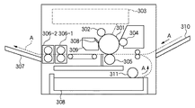
[画像形成装置の内部構造:図3]
図3は、レーザビーム露光方式を用いる画像形成装置の内部構造を示す概略図である。図3において、301は感光ドラム、302は帯電器(帯電ローラ)、303はレーザ光学系、304は現像器、305は転写ローラ、306−1、100−2は定着器、307は排紙トレー、308はブレード、309は排トナー容器、310は手差しトレイ、311は給紙ローラである。感光ドラム301上には、光の照射によって電気的特性が変化する光半導体層が形成されており、画像形成動作中は定速回転を行う。上記構成における画像形成動作には、以下の通りである。
[Internal structure of image forming apparatus: FIG. 3]
FIG. 3 is a schematic diagram showing the internal structure of an image forming apparatus using a laser beam exposure method. In FIG. 3, 301 is a photosensitive drum, 302 is a charger (charging roller), 303 is a laser optical system, 304 is a developing device, 305 is a transfer roller, 306-1 and 100-2 are fixing devices, and 307 is a paper discharge tray. , 308 are blades, 309 is a waste toner container, 310 is a manual feed tray, and 311 is a paper feed roller. On the
(1)帯電工程:帯電器(帯電ローラ)302により感光ドラム301上の光半導体層を均一に帯電させる。
(2)レーザ露光工程:感光ドラム301に向けて、レーザ光学系303により画像パターンを照射して静電潜像を形成する。
(3)現像工程:現像器304により、静電潜像上にトナーを付着させる。
(4)転写工程:転写ローラ305により、トナーが付着した像を記録録紙上に転写させる。
(5)定着工程:2台の直列に配置された定着器100−1、100−2により、記録紙の加熱及び加圧を行い、転写された像のトナーを記録紙上に定着させた後、記録紙を排紙トレー307上に排出する。
(6)クリーニング工程:記録紙上に転写しきらずに感光ドラム301上に残ったトナーをブレード308によりかき落し、かき落されたトナーは排トナー容器309内に蓄積される。
(1) Charging step: The photo semiconductor layer on the
(2) Laser exposure step: An electrostatic latent image is formed by irradiating the
(3) Development step: Toner is deposited on the electrostatic latent image by the
(4) Transfer process: The
(5) Fixing step: After fixing and transferring the toner of the transferred image on the recording paper by heating and pressurizing the recording paper by the two fixing devices 100-1 and 100-2 arranged in series, The recording paper is discharged onto the
(6) Cleaning step: The toner remaining on the
上記の工程に従って画像形成動作が行われる。尚、記録紙は、図中破線部Aに示すように、給紙カセット308または手差しトレイ310に積載され、給紙ローラ311により、感光ドラム301面に搬送される。
[定着器の異常処理を行う制御構成(第1の構成):図1]
次に、上記説明した画像形成装置を用いて画像記録を行う際に、2台の定着器のうちの少なくとも1つの定着器が異常となった場合を例に取り、そのときの異常処理の制御構成について説明する。
An image forming operation is performed according to the above steps. Note that the recording paper is stacked on the
[Control Configuration for Performing Fixing Unit Abnormal Processing (First Configuration): FIG. 1]
Next, when performing image recording using the image forming apparatus described above, a case where at least one of the two fixing devices becomes abnormal is taken as an example, and control of abnormal processing at that time is performed. The configuration will be described.
なお以下の説明では、説明を簡単にするため、各定着器ごとに定着ヒータの上限温度Tmax(例えば、230℃)と下限温度Tmin(例えば、70℃)が設定されているものとし、各定着器が異常となる場合とは、(1)各定着ヒータの測定温度が上限温度Tmaxを所定時間ta(例えば、2秒)以上越えている場合(過昇温検知の場合)、あるいは(2)各定着ヒータの測定温度が所定時間tb(例えば、3.5分)経過しても下限温度Tminに達しない場合(低温検知の場合)とする。 In the following description, for the sake of simplicity, it is assumed that an upper limit temperature Tmax (for example, 230 ° C.) and a lower limit temperature Tmin (for example, 70 ° C.) of the fixing heater are set for each fixing device. The case where the apparatus becomes abnormal is (1) when the measured temperature of each fixing heater exceeds the upper limit temperature Tmax for a predetermined time ta (for example, 2 seconds) or more (in the case of excessive temperature rise detection), or (2) The case where the measured temperature of each fixing heater does not reach the lower limit temperature Tmin even when a predetermined time tb (for example, 3.5 minutes) has elapsed (in the case of low temperature detection).
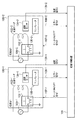
図1は、上記説明した定着器の異常処理を行う制御構成(第1の構成)を示すブロック図であり、定着制御装置101と2台の定着器100−1、100−2から構成される。定着器100−1、100−2は、それぞれリレー102−1、102−2、定着ヒータ103−1,103−2、温度センサ104−1、104−2、コンパレータ105−1,105−2から構成され、定着器100−1、100−2は外部電源であるAC電源106−1,106−2と接続されている。
FIG. 1 is a block diagram illustrating a control configuration (first configuration) for performing the above-described fixing device abnormality processing, and includes a fixing
定着制御装置101は、記録紙の種類や定着ヒータ温度、定着エラー検知等の情報から2台の定着ヒータ103−1、103−2のON/OFFを制御をするものであり、定着ヒータ103−1、103−2のON/OFFを調整することによって定着器100−1、100−2の温度調整をしたり、定着器100−1、100−2の異常時に定着ヒータをOFFしたりすることができる。リレー102−1、102−2は、ヒータON/OFF信号107−1、107−2によって制御され、定着ヒータ103−1、103−2へのAC電源106−1、106−2の供給を制御するものである。定着ヒータ103−1、103−2は、トナーを記録紙上に定着させるための熱源を発生させるものである。温度センサ104−1、104−2は、定着ヒータ103−1、103−2の温度を測定するものである。
The fixing
コンパレータ105−1、105−2は、温度センサ104−1、104−2の測定温度(定着ヒータ103−1、103−2の温度)を予め設定されている温度Tmax(所定温度)と比較して、その測定温度が所定温度を超えているかどうか判別し、この測定温度が所定温度Tmaxを超えた場合には、コンパレータ105−1、105−2の出力信号をアクティブとして108−1、108−2に示すエラー信号1,エラー信号2(定着ヒータ103−1、103−2が異常であることを示す信号)を出力する。一方、コンパレータ105−1、105−2は、この測定温度が所定温度Tmaxを超えていない場合には、コンパレータ105−1、105−2は、その出力信号をアクティブとしないので、エラー信号1,エラー信号2が出力されない。 The comparators 105-1 and 105-2 compare the measured temperatures of the temperature sensors 104-1 and 104-2 (the temperatures of the fixing heaters 103-1 and 103-2) with a preset temperature Tmax (predetermined temperature). Then, it is determined whether or not the measured temperature exceeds a predetermined temperature, and when the measured temperature exceeds the predetermined temperature Tmax, the output signals of the comparators 105-1 and 105-2 are set to be active, and 108-1 and 108- 2 is output (signal indicating that the fixing heaters 103-1 and 103-2 are abnormal). On the other hand, when the measured temperature does not exceed the predetermined temperature Tmax, the comparators 105-1 and 105-2 do not activate the output signal of the comparators 105-1 and 105-2. Error signal 2 is not output.
AC電源106−1、106−2は、定着ヒータ103−1、103−2の電源である。107−1、107−2はリレー102−1、102−2のON/OFF信号であり、定着ヒータ103−1、103−2への電源供給を制御する信号である。109−1、109−2は温度信号であり、定着ヒータ103−1、103−2の温度を示すアナログデータである。 AC power sources 106-1 and 106-2 are power sources for fixing heaters 103-1 and 103-2. 107-1 and 107-2 are ON / OFF signals of the relays 102-1 and 102-2, and are signals for controlling power supply to the fixing heaters 103-1 and 103-2. Reference numerals 109-1 and 109-2 are temperature signals, which are analog data indicating the temperatures of the fixing heaters 103-1 and 103-2.
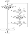
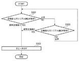
[第1の構成による定着器の異常時の処理:図2]
上記説明した定着器100−1、100−2および定着制御装置101の構成にて、定着制御装置101が、2台の定着器100−1、100−2のコンパレータ105−1、105−2の少なくともどちらか一方の異常を検知したとき(過昇温検知、あるいは低温検知の場合)の制御フローについて図2を用いて説明する。なお、以下の説明では、説明を容易にするため、図2による処理の一例として図9に示す温度推移の具体例を用いて説明するが、図9以外の温度推移でも以下の説明は適用できる。
[Processing when the fixing device is abnormal in the first configuration: FIG. 2]
In the configuration of the fixing devices 100-1 and 100-2 and the fixing
図9は、温度センサ104−1、104−2によって測定された定着ヒータ103−1、103−2の温度プロファイルの一例を示すものであり、定着ヒータ103−1、103−2が設定下限温度Tminとして70℃、設定上限限温度Tmaxとして230℃が設定されている場合において、定着ヒータ103−1、103−2を加熱した場合の温度プロファイルの一例を示すものであり、第1の温度プロファイルは過昇温検知の場合(すなわち、設定上限温度Tmax(230℃)を超える温度が設定時間ta(2秒間)以上検出された場合)を示し、第2の温度プロファイルは低温検知の場合(すなわち、設定下限温度Tmin(70℃)以下の温度が設定時間tb(3.5分)以上検出された場合)、第3の温度プロファイルは正常に加熱されている場合(すなわち、設定温度範囲(70〜230℃))を示す。 FIG. 9 shows an example of the temperature profile of the fixing heaters 103-1 and 103-2 measured by the temperature sensors 104-1 and 104-2. The fixing heaters 103-1 and 103-2 are set lower limit temperatures. FIG. 6 shows an example of a temperature profile when the fixing heaters 103-1 and 103-2 are heated when Tmin is set to 70 ° C. and the set upper limit temperature limit Tmax is set to 230 ° C. Indicates the case of overheating detection (that is, the temperature exceeding the set upper limit temperature Tmax (230 ° C.) is detected for the set time ta (2 seconds) or more), and the second temperature profile is the case of low temperature detection (that is, When the temperature lower than the set lower limit temperature Tmin (70 ° C.) is detected for the set time tb (3.5 minutes) or longer), the third temperature profile is positive. If it is heated to (i.e., set temperature range (70-230 ° C.)) shows a.
まず、図2のステップS101において、定着器100−1のコンパレータ105−1の出力信号がアクティブとなりエラー信号108−1が所定時間(ta:2秒)以上継続すると(所定上限温度Tmax230℃が2秒以上継続する)、ステップS102に進み、リレー102−1およびリレー102−2をOFFにし、全ての定着器の定着ヒータ(すなわち、定着ヒータ103−1、103−2)の加熱を停止する。(図9の例では、定着ヒータ103−1が第1の温度プロファイルで加熱された場合の時刻t2における処理である。) First, in step S101 of FIG. 2, when the output signal of the comparator 105-1 of the fixing device 100-1 becomes active and the error signal 108-1 continues for a predetermined time (ta: 2 seconds) or longer (the predetermined upper limit temperature Tmax 230 ° C. is 2). In step S102, the relay 102-1 and the relay 102-2 are turned OFF, and the heating of the fixing heaters (that is, the fixing heaters 103-1 and 103-2) of all the fixing devices is stopped. (In the example of FIG. 9, this is the process at time t2 when the fixing heater 103-1 is heated with the first temperature profile.)
一方、ステップS101において、定着器100−1のコンパレータ105−1の出力信号がアクティブでない場合(エラー信号108−1が出力されていない場合)には、ステップ103に進み、定着器100−1の温度信号109−1が所定時間以内(tb:3.5分)に所定温度以上(tmin:70℃)になっているかどうかをチェックし、所定時間以内(tb:3.5分)に所定温度以上(tmin:70℃)になっていなければ、ステップS102にすすみ、リレー102−1およびリレー102−2をOFFにし、全ての定着器の定着ヒータ(すなわち、定着ヒータ103−1、103−2)の加熱を停止する。(図9の例では、定着ヒータ103−1が第2の温度プロファイルで加熱された場合の時刻t3における処理である。) On the other hand, when the output signal of the comparator 105-1 of the fixing device 100-1 is not active in step S101 (when the error signal 108-1 is not output), the process proceeds to step 103, and the fixing device 100-1 outputs. It is checked whether the temperature signal 109-1 is equal to or higher than a predetermined temperature (tmin: 70 ° C.) within a predetermined time (tb: 3.5 minutes), and the predetermined temperature is determined within a predetermined time (tb: 3.5 minutes). If not (tmin: 70 ° C.), the flow proceeds to step S102, the relay 102-1 and the relay 102-2 are turned off, and the fixing heaters of all the fixing devices (that is, the fixing heaters 103-1, 103-2). ) Stop heating. (In the example of FIG. 9, this is the process at time t3 when the fixing heater 103-1 is heated with the second temperature profile.)
一方、ステップS103において、定着器100−1の温度信号109−1が所定時間以内(tb:3.5分)に所定温度(tmin:70℃)以上になっている場合には、ステップS104に移行する。(図9の例では、定着ヒータ103−1が第3の温度プロファイルで加熱された場合の時刻t3における処理である。) On the other hand, in step S103, if the temperature signal 109-1 of the fixing device 100-1 is equal to or higher than the predetermined temperature (tmin: 70 ° C.) within the predetermined time (tb: 3.5 minutes), the process proceeds to step S104. Transition. (In the example of FIG. 9, this is the process at time t3 when the fixing heater 103-1 is heated with the third temperature profile.)
ステップS104では、定着器100−2のコンパレータ105−2の出力信号がアクティブとなりエラー信号108−2が所定時間(ta:2秒)以上継続すると(所定上限温度Tmax230℃が2秒以上継続する場合)、ステップS102に進み、リレー102−1およびリレー102−2をOFFにし、全ての定着器の定着ヒータ(すなわち、定着ヒータ103−1、103−2)の加熱を停止する。(図9の例では、定着ヒータ103−2が第1の温度プロファイルで加熱された場合の時刻t2における処理である。)
一方、ステップS104において、定着器100−2のコンパレータ105−2の出力信号がアクティブでない場合(エラー信号108−2が出力されていない場合)には、ステップ105に進み、定着器100−2の温度信号109−2が所定時間以内(tb:3.5分)に所定温度以上(tmin:70℃)になっているかどうかをチェックし、所定時間以内(tb:3.5分)に所定温度以上(tmin:70℃)なっていなければ、ステップ102にすすみ、リレー102−1およびリレー102−2をOFFにし、全ての定着器の定着ヒータ(すなわち、定着ヒータ103−1、103−2)の加熱を停止する。(図9の例では、定着ヒータ103−2が第2の温度プロファイルで加熱された場合の時刻t3における処理である。)
In step S104, when the output signal of the comparator 105-2 of the fixing device 100-2 becomes active and the error signal 108-2 continues for a predetermined time (ta: 2 seconds) or longer (when the predetermined upper limit temperature Tmax 230 ° C. continues for 2 seconds or longer). In step S102, the relay 102-1 and the relay 102-2 are turned OFF, and the heating of the fixing heaters (that is, the fixing heaters 103-1 and 103-2) of all the fixing devices is stopped. (In the example of FIG. 9, this is processing at time t2 when the fixing heater 103-2 is heated with the first temperature profile.)
On the other hand, in step S104, if the output signal of the comparator 105-2 of the fixing device 100-2 is not active (if the error signal 108-2 is not output), the process proceeds to step 105, where the fixing device 100-2 is connected. It is checked whether the temperature signal 109-2 is equal to or higher than a predetermined temperature (tmin: 70 ° C.) within a predetermined time (tb: 3.5 minutes), and the predetermined temperature is determined within a predetermined time (tb: 3.5 minutes). If not (tmin: 70 ° C.), the process proceeds to step 102, the relay 102-1 and the relay 102-2 are turned off, and the fixing heaters of all the fixing devices (that is, the fixing heaters 103-1, 103-2). Stop heating. (In the example of FIG. 9, this is processing at time t3 when the fixing heater 103-2 is heated with the second temperature profile.)
一方、ステップS105において、定着器100−2の温度信号109−2が所定時間以内(tb:3.5分)に所定温度(tmin:70℃)以上になっている場合には、ステップS101に移行する。(図9の例では、定着ヒータ103−2が第3の温度プロファイルで加熱された場合の時刻t3における処理である。) On the other hand, if the temperature signal 109-2 of the fixing device 100-2 is equal to or higher than the predetermined temperature (tmin: 70 ° C.) within the predetermined time (tb: 3.5 minutes) in step S105, the process proceeds to step S101. Transition. (In the example of FIG. 9, this is the process at time t3 when the fixing heater 103-2 is heated with the third temperature profile.)
以上説明したように、本発明の画像形成装置は、2台の定着器と定着制御装置を有し、定着器はそれぞれに、定着ヒータに電力を供給するスイッチと、定着ヒータの温度を測定する温度センサと、測定された温度から定着ヒータが正常に作動しているか否かを判断し、異常の場合にエラー信号を出力するコンパレータとを有する。そのため、コンパレータのうちの少なくとも一つが異常信号を出力すると、定着制御装置は、2台の定着器の全てに対して電力の供給を停止するようにスイッチを制御することができるため、本発明の画像形成装置は、より安全に画像を形成することができる。 As described above, the image forming apparatus of the present invention has two fixing devices and a fixing control device, and each fixing device measures the temperature of the fixing heater and the switch for supplying power to the fixing heater. It has a temperature sensor and a comparator that determines whether or not the fixing heater is operating normally from the measured temperature and outputs an error signal in the case of an abnormality. Therefore, when at least one of the comparators outputs an abnormal signal, the fixing control device can control the switch so as to stop supplying power to all of the two fixing devices. The image forming apparatus can form an image more safely.
[定着器の異常処理を行う制御構成(第2の構成):図4]
以上の説明では、図1に示す定着制御装置と定着器が温度センサを有する構成における定着器の異常処理について説明したが、以上説明した処理と同様の処理は、図4に示す構成でも行うことができる。なお、図4の処理は、図1と図2を用いて説明した処理と類似するので、共通する点の説明は省略し、図1と異なる点についてのみ以下の説明説明する。
[Control Configuration for Performing Fixing Device Abnormal Processing (Second Configuration): FIG. 4]
In the above description, the fixing control abnormality processing in the configuration in which the fixing control device and the fixing device shown in FIG. 1 have the temperature sensor has been described. However, the same processing as the processing described above is also performed in the configuration shown in FIG. Can do. The process in FIG. 4 is similar to the process described with reference to FIGS. 1 and 2, so the description of the common points is omitted, and only the differences from FIG. 1 are described below.
図4は、図1で説明した定着器の異常処理を別の構成で行う場合の制御系を示すブロック図であり、定着制御装置201と2台の定着器200−1、200−2から構成される。図4の定着器200−1、200−2は、それぞれリレー202−1、202−2、定着ヒータ203−1,203−2、温度センサ204−1、204−2、コンパレータ205−1,205−2、AND回路210−1、210−2から構成され、定着器200−1、200−2は外部電源であるAC電源206−1,206−2と接続されている。
FIG. 4 is a block diagram showing a control system in a case where the fixing unit abnormality processing described with reference to FIG. 1 is performed with another configuration, and includes a fixing
図4が図1と異なる点は、図1のようにコンパレータ205−1,205−2の出力信号がアクティブとなるときのエラー信号208を定着制御装置201に出力するのではなく、定着器200−1、200−2内のAND回路210−1、210−2に入力し、このAND回路210−1、210−2の出力信号を用いて、リレー202−1、202−2の制御を行う点である。(ここで、コンパレータ205−1,205−2はオープンコレクタ出力で出力される。)
4 differs from FIG. 1 in that the
すなわち、定着ヒータの温度が設定温度の上限値を超えた場合、コンパレータ205−1,205−2の出力信号がアクティブになりエラー信号が出力されるので、その信号がAND回路210−1、210−2に入力される。すると、AND回路210−1、210−2は出力信号を出力し、リレー202−1、202−2がそれぞれOFFされて、全ての定着器の定着ヒータの加熱(すなわち、定着ヒータ203−1、203−2)が停止される。 That is, when the temperature of the fixing heater exceeds the upper limit value of the set temperature, the output signals of the comparators 205-1 and 205-2 become active and an error signal is output. -2. Then, the AND circuits 210-1 and 210-2 output output signals, and the relays 202-1 and 202-2 are respectively turned off to heat the fixing heaters of all the fixing devices (that is, the fixing heater 203-1, 203-2) is stopped.
このようにして、図4に示す第2の構成では定着器200−1、200−2のいずれかの定着ヒータの測定温度が設定上限温度Tmaxを超えた場合には、定着ヒータの異常と判別して、2台の定着器の全てに対して電力の供給を停止するようにスイッチを制御する。そのため、本発明の画像形成装置は、より安全に画像を形成することができる。 In this manner, in the second configuration shown in FIG. 4, when the measured temperature of the fixing heater of either of the fixing devices 200-1 and 200-2 exceeds the set upper limit temperature Tmax, it is determined that the fixing heater is abnormal. Then, the switch is controlled so as to stop the power supply to all of the two fixing devices. Therefore, the image forming apparatus of the present invention can form an image more safely.
[定着器の異常処理を行う制御構成(第3の構成):図5]
図1、図4による定着器の異常処理の説明では、定着器が温度センサを用いた構成による例であったが、温度センサの代わりに図5に示すようにサーモスイッチを用いた構成でも本発明は実現は可能である。以下にその構成における異常処理について説明する。なお、以下の説明では、図1,図2を用いたときと共通する部分の説明は省略し、異なる点についてのみ説明する。
[Control Configuration for Performing Fixing Device Abnormality Processing (Third Configuration): FIG. 5]
In the description of the abnormality processing of the fixing device shown in FIGS. 1 and 4, the fixing device is an example using a temperature sensor, but this configuration is also possible using a thermoswitch as shown in FIG. 5 instead of the temperature sensor. The invention is realizable. The abnormality process in the configuration will be described below. In the following description, description of parts common to those in FIGS. 1 and 2 is omitted, and only different points will be described.
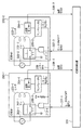
図5は、サーモスイッチを用いた構成の画像形成装置における定着器の異常処理を行う制御系を示すブロック図であり、定着制御装置401と2台の定着器400−1、400−2から構成される。定着器400−1、400−2は、それぞれリレー402−1、402−2、定着ヒータ403−1,403−2、サーモスイッチ404−1、404−2、温度センサ407−1、407−2、AND回路409−1、409−2から構成され、定着器400−1、400−2は外部電源であるAC電源406−1,406−2と接続されている。
FIG. 5 is a block diagram showing a control system for performing abnormality processing of a fixing device in an image forming apparatus having a configuration using a thermo switch. The control system includes a fixing
定着制御装置401は、記録紙の種類や定着ヒータ温度、定着エラー検知等の情報から2台の定着ヒータ403−1、403−2のON/OFFを制御をするものであり、定着ヒータ403−1、403−2のON/OFFを調整することによって定着器400−1、400−2の温度調整をしたり、定着器400−1、400−2の異常時に定着ヒータをOFFしたりすることができる。リレー402−1、402−2は、AND回路409−1、409−2の出力信号によって制御され、定着ヒータ403−1、403−2へのAC電源406−1、406−2の供給を制御するものである。
The fixing
ここで、AND回路409−1、409−2の出力信号は、ヒータON/OFF信号405−1、405−2、サーモスイッチ404−1、404−2の出力信号であるSW1信号、SW2信号の3つの信号によって制御される。すなわち、3つ全ての信号が入力されるとAND回路409−1、409−2は出力信号を出力し、リレー402−1、402−2を作動して定着ヒータ403−1、403−2へAC電源406−1、406−2より電力を供給する。一方、3つの信号のうち1つ、例えば、サーモスイッチ404−1、404−2のいずれかが切断され、SW1信号、SW2信号の1つが入力されるされなくなると、AND回路409−1、409−2は出力信号を出力しなくなるため、リレー402−1、402−2が作動せず、定着ヒータ403−1、403−2へのAC電源406−1、406−2からの電力の供給は停止する。 Here, the output signals of the AND circuits 409-1 and 409-2 are the heater ON / OFF signals 405-1 and 405-2, the SW1 signal and the SW2 signal that are the output signals of the thermo switches 404-1 and 404-2, respectively. Controlled by three signals. That is, when all three signals are input, the AND circuits 409-1 and 409-2 output output signals and operate the relays 402-1 and 402-2 to the fixing heaters 403-1 and 403-2. Power is supplied from AC power sources 406-1 and 406-2. On the other hand, when one of the three signals, for example, one of the thermo switches 404-1 and 404-2 is disconnected and one of the SW1 signal and SW2 signal is not input, the AND circuits 409-1 and 409 -2 does not output an output signal, the relays 402-1 and 402-2 do not operate, and power supply from the AC power sources 406-1 and 406-2 to the fixing heaters 403-1 and 403-2 is not performed. Stop.
定着ヒータ403−1、403−2は、トナーを記録紙上に定着させるための熱源を発生させるものである。サーモスイッチ104−1、104−2は、定着ヒータ103−1、103−2の温度が所定温度Tmax(例えば、230℃)以上になると回路をOFFするスイッチである。リレーのON/OFF信号405−1、405−2は、定着ヒータへの電源供給を制御する信号であり、温度センサ407−1、407−2で測定された温度信号408−1,408−2によって制御される。406−1、406−2はAC電源であり、定着ヒータの電源である。温度センサ407−1、407−2は、定着ヒータ403−1、403−2の温度を測定するものである。温度信号408−1、408−2は、定着ヒータの温度を示すアナログデータである。 The fixing heaters 403-1 and 403-2 generate heat sources for fixing the toner on the recording paper. The thermo switches 104-1 and 104-2 are switches that turn off the circuit when the temperature of the fixing heaters 103-1 and 103-2 is equal to or higher than a predetermined temperature Tmax (for example, 230 ° C.). Relay ON / OFF signals 405-1 and 405-2 are signals for controlling power supply to the fixing heater, and temperature signals 408-1 and 408-2 measured by the temperature sensors 407-1 and 407-2. Controlled by. Reference numerals 406-1 and 406-2 denote AC power sources, which are power sources for the fixing heater. The temperature sensors 407-1 and 407-2 measure the temperatures of the fixing heaters 403-1 and 403-2. The temperature signals 408-1 and 408-2 are analog data indicating the temperature of the fixing heater.
[第3の構成による定着器の異常時の処理:図6]
上記説明した定着器400−1、400−2および定着制御装置401の構成にて、2台の定着器400−1、400−2のサーモスイッチ104−1、104−2の少なくともどちらか一方が設定上限温度Tmax以上の高温を検知してOFFにされたときの制御フローについて図6を用いて説明する。
[Processing when the fixing device is abnormal in the third configuration: FIG. 6]
In the configuration of the fixing devices 400-1 and 400-2 and the fixing
まず、図6のステップS201において、第1の定着器400−1のサーモスイッチ404−1がOFFの場合(上限温度Tmax以上の高温を検知した場合)、図5の構成からわかるようにステップS202に進み、全リレー402−1、402−2はOFFされ、全ての定着器の定着ヒータの加熱(すなわち、定着ヒータ403−1、403−2)を停止する。 First, in step S201 of FIG. 6, when the thermo switch 404-1 of the first fixing device 400-1 is OFF (when a high temperature equal to or higher than the upper limit temperature Tmax is detected), as can be seen from the configuration of FIG. Then, all the relays 402-1 and 402-2 are turned off, and the heating of the fixing heaters of all the fixing devices (that is, the fixing heaters 403-1 and 403-2) is stopped.
一方、ステップS201において、定着器400−1のサーモスイッチ404−1がONの場合(上限温度Tmax以上の高温を検知しない場合)には、ステップS203に進み、第2の定着器400−2のサーモスイッチ404−2がOFFの場合(上限温度Tmax以上の高温を検知した場合)、図5の構成からわかるようにステップS202に進み、全リレー402−1、402−2はOFFされ、全ての定着器の定着ヒータの加熱(すなわち、定着ヒータ403−1、403−2)を停止する。 On the other hand, if the thermo switch 404-1 of the fixing device 400-1 is ON in Step S <b> 201 (when a high temperature equal to or higher than the upper limit temperature Tmax is not detected), the process proceeds to Step S <b> 203 and the second fixing device 400-2 is turned on. When the thermo switch 404-2 is OFF (when a high temperature equal to or higher than the upper limit temperature Tmax is detected), the process proceeds to step S202 as can be seen from the configuration of FIG. 5, and all the relays 402-1 and 402-2 are turned OFF, Heating of the fixing heater of the fixing device (that is, fixing heaters 403-1 and 403-2) is stopped.
一方、ステップS203において、定着器400−2のサーモスイッチ404−2がONの場合(上限温度Tmax以上の高温を検知しない場合)には、ステップS201に戻る。 On the other hand, when the thermo switch 404-2 of the fixing device 400-2 is ON in step S203 (when a high temperature equal to or higher than the upper limit temperature Tmax is not detected), the process returns to step S201.
このようにして、図5に示す第3の構成でも定着器400−1、400−2のいずれかの定着ヒータの測定温度が設定上限温度Tmax以上になるとサーモスイッチがOFFとなり定着ヒータの異常と判別して、2台の定着器の全てに対して電力の供給を停止するようにスイッチを制御する。そのため、本発明の画像形成装置は、より安全に画像を形成することができる。 As described above, even in the third configuration shown in FIG. 5, when the measured temperature of the fixing heater of either of the fixing devices 400-1 and 400-2 becomes equal to or higher than the set upper limit temperature Tmax, the thermo switch is turned OFF and the fixing heater is abnormal. The switch is controlled so as to stop the supply of power to all of the two fixing devices. Therefore, the image forming apparatus of the present invention can form an image more safely.
[定着器の異常処理を行う制御構成(第4の構成):図7]
図1、4,5に示した例の構成の定着器の異常処理は、温度の異常が検知されたときに定着ヒータをOFFする構成であったが、この異常処理は温度の検出によって行うものだけに限ることはない。たとえば、図7に一例を示すように、定着器内および定着器制御装置内にシリアルI/Fを持ち、その通信が正常にできない場合に、画像形成装置の安全性確保のために定着器をOFFにする構成としてもよい。以下に、その構成における異常処理について説明する。
[Control Configuration for Performing Abnormal Processing of Fixing Unit (Fourth Configuration): FIG. 7]
The abnormality processing of the fixing device having the configuration shown in FIGS. 1, 4 and 5 is configured to turn off the fixing heater when a temperature abnormality is detected. This abnormality processing is performed by detecting the temperature. It is not limited to just. For example, as shown in FIG. 7, when a serial I / F is provided in the fixing device and the fixing device control device and communication cannot be performed normally, the fixing device is used to ensure the safety of the image forming apparatus. It may be configured to be turned off. Hereinafter, the abnormality process in the configuration will be described.
図7は、シリアルI/Fを用いた構成の画像形成装置における定着器の異常処理を行う制御系を示すブロック図であり、シリアルI/Fを含む制御IC510−3を有する定着制御装置501と2台の定着器500−1、500−2から構成される。定着器500−1、500−2は、それぞれリレー502−1、502−2、定着ヒータ503−1,503−2、温度センサ504−1、504−2、コンパレータ505−1,505−2、シリアルI/Fを含む制御IC510−1、510−2から構成され、定着器100−1、100−2は外部電源であるAC電源106−1,106−2と接続されている。
FIG. 7 is a block diagram showing a control system for performing an abnormality process of the fixing device in an image forming apparatus configured using a serial I / F. The
定着制御装置501は、記録紙種や定着ヒータ温度、定着エラー検知等の情報から2台の定着ヒータ503−1、503−2のON/OFF制御をするものであり、定着ヒータ503−1、503−2のON/OFFを調整することによって定着器500−1、500−2の温度調整をしたり、定着器500−1、500−2の異常時に定着ヒータをOFFしたりすることができる。リレー502−1、502−2は、ヒータON/OFF信号507−1、507−2によって制御され、定着ヒータ503−1、503−2へのAC電源506−1、506−2の供給を制御するものである。定着ヒータ503−1、503−2は、トナーを記録紙上に定着させるための熱源を発生させるものである。温度センサ504−1、504−2は、定着ヒータ503−1、503−2の温度を測定するものである。
The fixing
コンパレータ505−1、505−2は、温度センサ504−1、504−2の測定温度(定着ヒータ503−1、503−2の温度)を予め設定されている温度Tmax(所定温度)と比較して、その測定温度が所定温度を超えているかどうか判別し、この測定温度が所定温度Tmaxを超えた場合には、コンパレータ505−1、505−2の出力信号をアクティブとして508−1、508−2に示すエラー信号1,エラー信号2(定着ヒータ503−1、503−2が異常であることを示す信号)を出力する。一方、コンパレータ505−1、505−2は、この測定温度が所定温度Tmaxを超えていない場合には、コンパレータ505−1、505−2は、その出力信号をアクティブとしないので、エラー信号1,エラー信号2が出力されない。 The comparators 505-1 and 505-2 compare the measured temperatures of the temperature sensors 504-1 and 504-2 (the temperatures of the fixing heaters 503-1 and 503-2) with a preset temperature Tmax (predetermined temperature). Whether or not the measured temperature exceeds the predetermined temperature is determined, and when the measured temperature exceeds the predetermined temperature Tmax, the output signals of the comparators 505-1 and 505-2 are set to be active and the currents 508-1 and 508- are activated. 2 is output (signal indicating that the fixing heaters 503-1 and 503-2 are abnormal). On the other hand, when the measured temperature does not exceed the predetermined temperature Tmax, the comparators 505-1 and 505-2 do not activate their output signals. Error signal 2 is not output.
AC電源506−1、506−2は、定着ヒータの電源である。507−1、507−2はリレーのON/OFF信号であり、定着ヒータ503−1、503−2への電源供給を制御する信号である。509−1、509−2は温度信号であり、定着ヒータの温度を示すアナログデータである。510−1、510−2、510−3はシリアルI/Fを含む制御ICであり、510−1と510−3間、510−2と510−3間のデータの受け渡しをシリアル通信で行うことができる。 AC power sources 506-1 and 506-2 are power sources for the fixing heater. Reference numerals 507-1 and 507-2 are relay ON / OFF signals for controlling power supply to the fixing heaters 503-1 and 503-2. Reference numerals 509-1 and 509-2 denote temperature signals, which are analog data indicating the temperature of the fixing heater. 510-1, 510-2, and 510-3 are control ICs including a serial I / F, and transfer data between 510-1 and 510-3 and between 510-2 and 510-3 by serial communication. Can do.
なお、コンパレータ505−1からのエラー信号508−1をシリアルI/Fを含む制御IC510−1が受信すると、シリアルI/Fを含む制御IC510−1は、シリアルI/Fを含む制御IC510−3へのシリアル通信を停止し、同様に、コンパレータ505−2からのエラー信号508−2をシリアルI/Fを含む制御IC510−2が受信すると、シリアルI/Fを含む制御IC510−2はシリアルI/Fを含む制御IC510−3へのシリアル通信を停止することができる。このとき、シリアルI/Fを含む制御IC510−3は、その異常状態を検知すると、(例えば、シリアルI/Fを含む制御IC510−1からシリアルI/Fを含む制御IC510−3へのシリアル通信が停止されたことを検知する、または、シリアルI/Fを含む制御IC510−2からシリアルI/Fを含む制御IC510−3へのシリアル通信が停止されたことを検知すると)、リレーのON/OFF信号507−1、507−2を用いて全リレー502−1、502−2をOFFにし、全ての定着器の定着ヒータの加熱(すなわち、定着ヒータ503−1、503−2)を停止することができる。 When the control IC 510-1 including the serial I / F receives the error signal 508-1 from the comparator 505-1, the control IC 510-1 including the serial I / F is controlled by the control IC 510-3 including the serial I / F. Similarly, when the control IC 510-2 including the serial I / F receives the error signal 508-2 from the comparator 505-2, the control IC 510-2 including the serial I / F receives the serial I / F. Serial communication to the control IC 510-3 including / F can be stopped. At this time, when the control IC 510-3 including the serial I / F detects the abnormal state (for example, serial communication from the control IC 510-1 including the serial I / F to the control IC 510-3 including the serial I / F) ON / OFF of the relay is detected) or the serial communication from the control IC 510-2 including the serial I / F to the control IC 510-3 including the serial I / F is stopped). All relays 502-1 and 502-2 are turned OFF using OFF signals 507-1 and 507-2, and heating of the fixing heaters of all the fixing devices (that is, fixing heaters 503-1 and 503-2) is stopped. be able to.
[第4の構成による定着器の異常時の処理:図8]
上記説明した定着制御装置501と2台の定着器500−1、500−2の構成にて、定着器500−1と定着制御装置501とのシルアル通信、あるいは、定着器500−2と定着制御装置501とのシルアル通信の少なくともどちらか一方が通信できなくなったときの制御フローを図8に示す。この制御は、画像形成装置のCPU(不図示)がROM(不図示)に格納された制御プログラムに従ってRAM(不図示)を用いて各部を制御しながら実行するものである。
[Processing when the fixing device is abnormal according to the fourth configuration: FIG. 8]
With the configuration of the fixing
まず、図8のステップS301において、第1の定着器500−1と定着制御装置501とのシリアル通信が異常である場合(シリアルI/Fを含む制御IC510−1がシリアルI/Fを含む制御IC510−3への応答信号が停止した場合、シリアル転送データに含まれるパリティビットによるパリティチェックがエラーである場合、同じデータの複数回送信によるデータコンペアでエラーがある場合、ループバックチェック(送信したデータをそのまま受信してデータ比較)でエラーがある場合)、ステップS302に進み、シリアルI/Fを含む制御IC510−3はその異常状態を検知(シリアルI/Fを含む制御IC510−1からシリアルI/Fを含む制御IC510−3へのシリアル通信が停止されたことを検知)すると、リレーのON/OFF信号507−1、507−2を用いて全リレー502−1、502−2をOFFにし、全ての定着器の定着ヒータの加熱(すなわち、定着ヒータ503−1、503−2)を停止する。
First, in step S301 in FIG. 8, when the serial communication between the first fixing device 500-1 and the fixing
一方、ステップS301において、第1の定着器500−1と定着制御装置501とのシルアル通信が正常に通信できる場合にはステップ303に進み、第2の定着器500−2と定着制御装置501とのシルアル通信が異常である場合(シリアルI/Fを含む制御IC510−2がシリアルI/Fを含む制御IC510−3への応答信号が停止した場合、シリアル転送データに含まれるパリティビットによるパリティチェックがエラーである場合、同じデータの複数回送信によるデータコンペアでエラーがある場合、ループバックチェック(送信したデータをそのまま受信してデータ比較)でエラーがある場合)には、ステップS303に進み、シリアルI/Fを含む制御IC510−3はその異常状態を検知(シリアルI/Fを含む制御IC510−2からシリアルI/Fを含む制御IC510−3へのシリアル通信が停止されたことを検知)すると、リレーのON/OFF信号507−1、507−2を用いて全リレー502−1、502−2をOFFにし、全ての定着器の定着ヒータの加熱(すなわち、定着ヒータ503−1、503−2)を停止する。
On the other hand, if the serial communication between the first fixing device 500-1 and the fixing
一方、ステップS303において、シリアルI/Fを含む制御IC510−3がその異常状態を検知し無い場合には、ステップS201に戻る。 On the other hand, when the control IC 510-3 including the serial I / F does not detect the abnormal state in step S303, the process returns to step S201.
このようにして、図7に示す第4の構成では定着器200−1、200−2のいずれかが故障したことに起因して定着器500−1と定着制御装置501とのシルアル通信、あるいは、定着器500−2と定着制御装置501とのシルアル通信の少なくともどちらか一方が通信できなくなった場合には、定着器の異常と判別して、2台の定着器の全てに対して電力の供給を停止するようにスイッチを制御する。そのため、本発明の画像形成装置は、より安全に画像を形成することができる。
In this way, in the fourth configuration shown in FIG. 7, the serial communication between the fixing device 500-1 and the fixing
[他の実施形態]
なお、本発明は、例えば、装置、方法、プログラムもしくは記憶媒体などとしての実施態様を取ることが可能であり、具体的には、複数の機器(例えばホストコンピュータ、インターフェース機器、リーダ、プリンタなど)から構成されるシステムに適用しても、一つの機器からなる装置(例えば、複写機、ファクシミリ装置など)に適用してもよい。
[Other Embodiments]
The present invention can take the form of, for example, an apparatus, a method, a program, or a storage medium. Specifically, a plurality of devices (for example, a host computer, an interface device, a reader, a printer, etc.) The present invention may be applied to a system configured from the above, or may be applied to an apparatus (for example, a copier, a facsimile machine, etc.) including one device.
また、本発明の目的は、前述した実施形態の機能を実現するソフトウェアのプログラムコードを記録した記憶媒体(または記録媒体)を、システムあるいは装置に供給し、そのシステムあるいは装置のコンピュータ(またはCPUやMPU)が記憶媒体に格納されたプログラムコードを読み出し実行することによっても、達成されることは言うまでもない。この場合、記憶媒体から読み出されたプログラムコード自体が前述した実施形態の機能を実現することになり、そのプログラムコードを記憶した記憶媒体は本発明を構成することになる。 Another object of the present invention is to supply a storage medium (or recording medium) in which a program code of software that realizes the functions of the above-described embodiments is recorded to a system or apparatus, and the computer (or CPU or Needless to say, this can also be achieved by the MPU) reading and executing the program code stored in the storage medium. In this case, the program code itself read from the storage medium realizes the functions of the above-described embodiments, and the storage medium storing the program code constitutes the present invention.
また、コンピュータが読み出したプログラムコードを実行することにより、前述した実施形態の機能が実現されるだけでなく、そのプログラムコードの指示に基づき、コンピュータ上で稼働しているオペレーティングシステム(OS)などが実際の処理の一部または全部を行い、その処理によって前述した実施形態の機能が実現される場合も含まれることは言うまでもない。 Further, by executing the program code read by the computer, not only the functions of the above-described embodiments are realized, but also an operating system (OS) running on the computer based on the instruction of the program code. It goes without saying that a case where the function of the above-described embodiment is realized by performing part or all of the actual processing and the processing is included.
さらに、記憶媒体から読み出されたプログラムコードが、コンピュータに挿入された機能拡張カードやコンピュータに接続された機能拡張ユニットに備わるメモリに書込まれた後、そのプログラムコードの指示に基づき、その機能拡張カードや機能拡張ユニットに備わるCPUなどが実際の処理の一部または全部を行い、その処理によって前述した実施形態の機能が実現される場合も含まれることは言うまでもない。本発明を上記記憶媒体に適用する場合、その記憶媒体には、先に説明した(図2、6、8に示す)フローチャートに対応するプログラムコードが格納されることになる。 Furthermore, after the program code read from the storage medium is written into a memory provided in a function expansion card inserted into the computer or a function expansion unit connected to the computer, the function is based on the instruction of the program code. It goes without saying that the CPU or the like provided in the expansion card or the function expansion unit performs part or all of the actual processing and the functions of the above-described embodiments are realized by the processing. When the present invention is applied to the above-described storage medium, the storage medium stores program codes corresponding to the flowcharts described above (shown in FIGS. 2, 6 and 8).
100−1 定着器1
100−2 定着器2
101 定着制御部
102−1 リレー
102−2 リレー
103−1 定着ヒータ
103−2 定着ヒータ
104−1 温度センサ
104−2 温度センサ
105−1 コンパレータ
105−2 コンパレータ
106−1 AC電源
106−2 AC電源
107−1 ヒータON/OFF信号1
107−2 ヒータON/OFF信号2
108−1 エラー信号1
108−2 エラー信号2
109−1 温度信号1
109−2 温度信号2
200−1 定着器1
200−2 定着器2
201 定着制御部
202−1 リレー
202−2 リレー
203−1 定着ヒータ
203−2 定着ヒータ
204−1 温度センサ
204−2 温度センサ
205−1 コンパレータ
205−2 コンパレータ
206−1 AC電源
206−2 AC電源
207−1 ヒータON/OFF信号1
207−2 ヒータON/OFF信号2
208 エラー信号1
209−1 温度信号1
209−2 温度信号2
210−1 AND回路
210−2 AND回路
400−1 定着器1
400−2 定着器2
401 定着制御部
402−1 リレー
402−2 リレー
403−1 定着ヒータ
403−2 定着ヒータ
404−1 サーモスイッチ
404−2 サーモスイッチ
405−1 ヒータON/OFF信号1
405−2 ヒータON/OFF信号2
406−1 AC電源
406−2 AC電源
407−1 温度センサ
407−2 温度センサ
408−1 温度信号1
408−2 温度信号2
409−1 AND回路
409−2 AND回路
500−1 定着器1
500−2 定着器2
501 定着制御部
502−1 リレー
502−2 リレー
503−1 定着ヒータ
503−2 定着ヒータ
504−1 温度センサ
504−2 温度センサ
505−1 コンパレータ
505−2 コンパレータ
506−1 AC電源
506−2 AC電源
507−1 ヒータON/OFF信号1
507−2 ヒータON/OFF信号2
508−1 エラー信号1
508−2 エラー信号2
509−1 温度信号1
509−2 温度信号2
510−1 シリアルI/Fを含む制御IC
510−2 シリアルI/Fを含む制御IC
510−3 シリアルI/Fを含む制御IC
100-1
100-2 Fixing device 2
101 Fixing Control Unit 102-1 Relay 102-2 Relay 103-1 Fixing Heater 103-2 Fixing Heater 104-1 Temperature Sensor 104-2 Temperature Sensor 105-1 Comparator 105-2 Comparator 106-1 AC Power Supply 106-2 AC Power Supply 107-1 Heater ON /
107-2 Heater ON / OFF signal 2
108-1
108-2 Error signal 2
109-1
109-2 Temperature signal 2
200-1
200-2 Fixing device 2
201 Fixing Control Unit 202-1 Relay 202-2 Relay 203-1 Fixing Heater 203-2 Fixing Heater 204-1 Temperature Sensor 204-2 Temperature Sensor 205-1 Comparator 205-2 Comparator 206-1 AC Power Supply 206-2 AC Power Supply 207-1 Heater ON /
207-2 Heater ON / OFF signal 2
208
209-1
209-2 Temperature signal 2
210-1 AND circuit 210-2 AND circuit 400-1
400-2 Fixing device 2
401 Fixing Control Unit 402-1 Relay 402-2 Relay 403-1 Fixing Heater 403-2 Fixing Heater 404-1 Thermo Switch 404-2 Thermo Switch 405-1 Heater ON /
405-2 Heater ON / OFF signal 2
406-1 AC power supply 406-2 AC power supply
407-1 Temperature sensor 407-2 Temperature sensor 408-1
408-2 Temperature signal 2
409-1 AND circuit 409-2 AND circuit 500-1
500-2 Fixing device 2
501 Fixing Control Unit 502-1 Relay 502-2 Relay 503-1 Fixing Heater 503-2 Fixing Heater 504-1 Temperature Sensor 504-2 Temperature Sensor 505-1 Comparator 505-2 Comparator 506-1 AC Power Supply 506-2 AC Power Supply
507-1 Heater ON /
507-2 Heater ON / OFF signal 2
508-1
508-2 Error signal 2
509-1
509-2 Temperature signal 2
510-1 Control IC including serial I / F
510-2 Control IC including serial I / F
510-3 Control IC including serial I / F
Claims (8)
前記定着器は、それぞれ、
前記定着ヒータに電力を供給するスイッチと、
前記定着ヒータの異常を検知する異常検知手段と、を有し、
前記画像形成装置は、
前記異常検知手段のうちの少なくとも一つによって異常が検知されると、前記複数の定着器の全てに対して前記電力の供給を停止するように前記スイッチを制御する制御手段を有することを特徴とする画像形成装置。 An image forming apparatus including a plurality of fixing devices each having a fixing heater for fixing a developer to a recording medium,
The fixing devices are respectively
A switch for supplying power to the fixing heater;
An abnormality detecting means for detecting an abnormality of the fixing heater,
The image forming apparatus includes:
When an abnormality is detected by at least one of the abnormality detection means, the apparatus has a control means for controlling the switch so as to stop the supply of the power to all of the plurality of fixing devices. Image forming apparatus.
前記定着器は、それぞれ、
前記定着ヒータに電力を供給するスイッチと、
前記定着ヒータの異常を検知する異常検知手段と、を有し、
前記制御方法は、
前記異常検知手段のうちの少なくとも一つによって異常が検知されると、前記複数の定着器の全てに対して前記電力の供給を停止するように前記スイッチを制御する制御工程を有することを特徴とする画像形成装置の制御方法。 A control method for an image forming apparatus having a plurality of fixing devices including a fixing heater for fixing a developer to a recording medium,
The fixing devices are respectively
A switch for supplying power to the fixing heater;
An abnormality detecting means for detecting an abnormality of the fixing heater,
The control method is:
When an abnormality is detected by at least one of the abnormality detection means, the method includes a control step of controlling the switch so as to stop supplying the power to all of the plurality of fixing devices. Control method for image forming apparatus.
前記定着器は、それぞれ、
前記定着ヒータに電力を供給するスイッチと、
シリアルデータによる通信をするシリアル通信手段と、を有し、
前記画像形成装置は、
前記シリアル通信手段のうちの少なくとも一つによって通信異常が検知されると、前記複数の定着器の全てに対して前記電力の供給を停止するように前記スイッチを制御する制御手段を有することを特徴とする画像形成装置。 An image forming apparatus including a plurality of fixing devices each having a fixing heater for fixing a developer to a recording medium,
The fixing devices are respectively
A switch for supplying power to the fixing heater;
Serial communication means for performing communication by serial data,
The image forming apparatus includes:
When a communication abnormality is detected by at least one of the serial communication means, control means is provided for controlling the switch so as to stop supplying the power to all of the plurality of fixing devices. An image forming apparatus.
Priority Applications (2)
| Application Number | Priority Date | Filing Date | Title |
|---|---|---|---|
| JP2004217771A JP2006039143A (en) | 2004-07-26 | 2004-07-26 | Image forming apparatus and its control method |
| US11/189,589 US20060018676A1 (en) | 2004-07-26 | 2005-07-26 | Image forming apparatus and control method therefor |
Applications Claiming Priority (1)
| Application Number | Priority Date | Filing Date | Title |
|---|---|---|---|
| JP2004217771A JP2006039143A (en) | 2004-07-26 | 2004-07-26 | Image forming apparatus and its control method |
Publications (2)
| Publication Number | Publication Date |
|---|---|
| JP2006039143A true JP2006039143A (en) | 2006-02-09 |
| JP2006039143A5 JP2006039143A5 (en) | 2007-07-19 |
Family
ID=35657286
Family Applications (1)
| Application Number | Title | Priority Date | Filing Date |
|---|---|---|---|
| JP2004217771A Pending JP2006039143A (en) | 2004-07-26 | 2004-07-26 | Image forming apparatus and its control method |
Country Status (2)
| Country | Link |
|---|---|
| US (1) | US20060018676A1 (en) |
| JP (1) | JP2006039143A (en) |
Cited By (2)
| Publication number | Priority date | Publication date | Assignee | Title |
|---|---|---|---|---|
| JP2009204784A (en) * | 2008-02-27 | 2009-09-10 | Sharp Corp | Fixing device and image forming device |
| JP2011221287A (en) * | 2010-04-09 | 2011-11-04 | Canon Inc | Image forming apparatus |
Families Citing this family (7)
| Publication number | Priority date | Publication date | Assignee | Title |
|---|---|---|---|---|
| JP4410199B2 (en) * | 2006-02-14 | 2010-02-03 | シャープ株式会社 | Fixing device |
| JP4298754B2 (en) * | 2007-01-31 | 2009-07-22 | キヤノン株式会社 | Image forming apparatus and image forming method |
| JP4992572B2 (en) * | 2007-06-26 | 2012-08-08 | ブラザー工業株式会社 | Power supply cutoff circuit and droplet discharge device |
| JP5693190B2 (en) * | 2010-12-08 | 2015-04-01 | キヤノン株式会社 | Image forming apparatus |
| JP5882701B2 (en) * | 2011-12-02 | 2016-03-09 | キヤノン株式会社 | Image forming apparatus |
| JP5757963B2 (en) * | 2013-01-11 | 2015-08-05 | 京セラドキュメントソリューションズ株式会社 | Image forming apparatus |
| JP2018129622A (en) * | 2017-02-07 | 2018-08-16 | 株式会社東芝 | Image forming apparatus |
Family Cites Families (5)
| Publication number | Priority date | Publication date | Assignee | Title |
|---|---|---|---|---|
| US5436711A (en) * | 1993-11-29 | 1995-07-25 | Xerox Corporation | Multilevel fusing apparatus |
| GB2290259B (en) * | 1994-06-17 | 1997-09-10 | Oki Electric Ind Co Ltd | Image fixing device for use with electrophotographic printing apparatus |
| US6671487B2 (en) * | 2002-01-25 | 2003-12-30 | Hewlett-Packard Development Company, L.P. | Fuser assembly including first and second fusers |
| JP3945281B2 (en) * | 2002-03-19 | 2007-07-18 | 富士ゼロックス株式会社 | Image forming apparatus |
| JP2004004712A (en) * | 2002-04-15 | 2004-01-08 | Canon Inc | Fixing device and image forming apparatus |
-
2004
- 2004-07-26 JP JP2004217771A patent/JP2006039143A/en active Pending
-
2005
- 2005-07-26 US US11/189,589 patent/US20060018676A1/en not_active Abandoned
Cited By (3)
| Publication number | Priority date | Publication date | Assignee | Title |
|---|---|---|---|---|
| JP2009204784A (en) * | 2008-02-27 | 2009-09-10 | Sharp Corp | Fixing device and image forming device |
| JP4649485B2 (en) * | 2008-02-27 | 2011-03-09 | シャープ株式会社 | Fixing apparatus, image forming apparatus, and abnormality detection method of fixing apparatus |
| JP2011221287A (en) * | 2010-04-09 | 2011-11-04 | Canon Inc | Image forming apparatus |
Also Published As
| Publication number | Publication date |
|---|---|
| US20060018676A1 (en) | 2006-01-26 |
Similar Documents
| Publication | Publication Date | Title |
|---|---|---|
| CN1321354C (en) | Fixing device | |
| US20060018676A1 (en) | Image forming apparatus and control method therefor | |
| JP2008134440A (en) | Image forming apparatus | |
| JP4194540B2 (en) | Image forming apparatus | |
| JP5488861B2 (en) | Image forming apparatus and method for controlling warm-up time in image forming apparatus | |
| JP2010117652A (en) | Image forming device and control method of the same | |
| US10401766B2 (en) | Image forming apparatus and image forming method with temperature and power-based productivity rate selection | |
| US8958711B2 (en) | Image forming apparatus | |
| US9031444B2 (en) | Image forming apparatus provided with fixing unit for fixing images formed on paper and method of controlling heaters of the apparatus | |
| JP2008003469A (en) | Heating device and image forming apparatus | |
| US9046836B2 (en) | Image forming apparatus for restricting excessive temperature rise of fixing member | |
| JP2019200403A (en) | Image forming apparatus | |
| US9316970B2 (en) | Image forming apparatus and method for controlling power supply to heater of fixing unit based on resistance value of heater | |
| JP7154854B2 (en) | Image forming apparatus and fixing device | |
| US10012933B2 (en) | Fixing device and image forming apparatus | |
| JP7468147B2 (en) | Image forming device | |
| JP2019148724A (en) | Image forming device and image forming method | |
| JP6716920B2 (en) | Image forming device | |
| JP6507831B2 (en) | Fixing device and image forming apparatus | |
| JP2015169910A (en) | image forming apparatus | |
| JP2012118228A (en) | Image forming apparatus | |
| JP4338474B2 (en) | Fixing device, image forming apparatus, and fixing device control method | |
| JP2009063725A (en) | Image forming device | |
| JP4577347B2 (en) | Image forming apparatus | |
| JP2010113256A (en) | Image forming apparatus |
Legal Events
| Date | Code | Title | Description |
|---|---|---|---|
| A521 | Written amendment |
Free format text: JAPANESE INTERMEDIATE CODE: A523 Effective date: 20070530 |
|
| A621 | Written request for application examination |
Free format text: JAPANESE INTERMEDIATE CODE: A621 Effective date: 20070530 |
|
| RD03 | Notification of appointment of power of attorney |
Free format text: JAPANESE INTERMEDIATE CODE: A7423 Effective date: 20070530 |
|
| A977 | Report on retrieval |
Free format text: JAPANESE INTERMEDIATE CODE: A971007 Effective date: 20091210 |
|
| A131 | Notification of reasons for refusal |
Free format text: JAPANESE INTERMEDIATE CODE: A131 Effective date: 20091214 |
|
| A521 | Written amendment |
Free format text: JAPANESE INTERMEDIATE CODE: A523 Effective date: 20100209 |
|
| A02 | Decision of refusal |
Free format text: JAPANESE INTERMEDIATE CODE: A02 Effective date: 20100308 |