JP5757963B2 - Image forming apparatus - Google Patents

Image forming apparatus Download PDF

Info

Publication number
JP5757963B2
JP5757963B2 JP2013003493A JP2013003493A JP5757963B2 JP 5757963 B2 JP5757963 B2 JP 5757963B2 JP 2013003493 A JP2013003493 A JP 2013003493A JP 2013003493 A JP2013003493 A JP 2013003493A JP 5757963 B2 JP5757963 B2 JP 5757963B2
Authority
JP
Japan
Prior art keywords
control unit
unit
heating
temperature
abnormality
Prior art date
Legal status (The legal status is an assumption and is not a legal conclusion. Google has not performed a legal analysis and makes no representation as to the accuracy of the status listed.)
Expired - Fee Related
Application number
JP2013003493A
Other languages
Japanese (ja)
Other versions
JP2014134727A (en
Inventor
慶之 小▲高▼
慶之 小▲高▼
Current Assignee (The listed assignees may be inaccurate. Google has not performed a legal analysis and makes no representation or warranty as to the accuracy of the list.)
Kyocera Document Solutions Inc
Original Assignee
Kyocera Document Solutions Inc
Priority date (The priority date is an assumption and is not a legal conclusion. Google has not performed a legal analysis and makes no representation as to the accuracy of the date listed.)
Filing date
Publication date
Application filed by Kyocera Document Solutions Inc filed Critical Kyocera Document Solutions Inc
Priority to JP2013003493A priority Critical patent/JP5757963B2/en
Priority to CN201410009203.7A priority patent/CN103926817B/en
Priority to US14/151,624 priority patent/US9031427B2/en
Publication of JP2014134727A publication Critical patent/JP2014134727A/en
Application granted granted Critical
Publication of JP5757963B2 publication Critical patent/JP5757963B2/en
Expired - Fee Related legal-status Critical Current
Anticipated expiration legal-status Critical

Links

Images

Classifications

    • GPHYSICS
    • G03PHOTOGRAPHY; CINEMATOGRAPHY; ANALOGOUS TECHNIQUES USING WAVES OTHER THAN OPTICAL WAVES; ELECTROGRAPHY; HOLOGRAPHY
    • G03GELECTROGRAPHY; ELECTROPHOTOGRAPHY; MAGNETOGRAPHY
    • G03G15/00Apparatus for electrographic processes using a charge pattern
    • G03G15/20Apparatus for electrographic processes using a charge pattern for fixing, e.g. by using heat
    • G03G15/2003Apparatus for electrographic processes using a charge pattern for fixing, e.g. by using heat using heat
    • G03G15/2014Apparatus for electrographic processes using a charge pattern for fixing, e.g. by using heat using heat using contact heat
    • G03G15/2053Structural details of heat elements, e.g. structure of roller or belt, eddy current, induction heating
    • GPHYSICS
    • G03PHOTOGRAPHY; CINEMATOGRAPHY; ANALOGOUS TECHNIQUES USING WAVES OTHER THAN OPTICAL WAVES; ELECTROGRAPHY; HOLOGRAPHY
    • G03GELECTROGRAPHY; ELECTROPHOTOGRAPHY; MAGNETOGRAPHY
    • G03G15/00Apparatus for electrographic processes using a charge pattern
    • G03G15/20Apparatus for electrographic processes using a charge pattern for fixing, e.g. by using heat
    • G03G15/2003Apparatus for electrographic processes using a charge pattern for fixing, e.g. by using heat using heat
    • G03G15/2014Apparatus for electrographic processes using a charge pattern for fixing, e.g. by using heat using heat using contact heat
    • G03G15/2039Apparatus for electrographic processes using a charge pattern for fixing, e.g. by using heat using heat using contact heat with means for controlling the fixing temperature
    • G03G15/205Apparatus for electrographic processes using a charge pattern for fixing, e.g. by using heat using heat using contact heat with means for controlling the fixing temperature specially for the mode of operation, e.g. standby, warming-up, error

Description

本発明は、誘導加熱を用いて用紙にトナーを定着させる画像形成装置に関する。   The present invention relates to an image forming apparatus that fixes toner onto a sheet using induction heating.

複合機、複写機、プリンター、FAX装置のような画像形成装置には、トナーを用いて画像形成を行うものがある。このような画像形成装置では、内部で用紙搬送を行いつつトナー像を用紙に転写し、加熱、加圧してトナー像を用紙に定着させる。そして、トナーを定着して印刷を行う画像形成装置には、誘導加熱方式で定着を行うものがある。   Some image forming apparatuses such as multifunction peripherals, copiers, printers, and fax machines perform image formation using toner. In such an image forming apparatus, a toner image is transferred onto a sheet while the sheet is conveyed inside, and the toner image is fixed on the sheet by heating and pressing. Some image forming apparatuses that perform printing with toner fixed thereon perform fixing by induction heating.

このような、誘導加熱方式により定着を行う定着制御装置が、特許文献1に記載されている。具体的に、特許文献1には、装置全体の動作を制御する主中央処理装置を有する本体制御回路と、定着用被加熱部材の温度を検知する温度センサと、電流供給を受けて定着用被加熱部材を誘導加熱するための励磁コイルと、主中央処理装置とは、独立した副中央処理装置を有して励磁コイルに対する電流供給を制御する誘導加熱制御回路と、を備え、主中央処理装置は、温度センサにより検知された温度情報に基づき、前記副中央処理装置に対する制御指示を電力指示信号のみで行う定着制御装置が記載されている。この構成により、2CPU方式として、基本的にCPUにかかる負荷を分散させ、誘導加熱定着方式本来の温度追従性の良さを活かし、緻密な誘導加熱制御を実現しようとする(特許文献1:請求項1、段落[0011]参照)。   Such a fixing control device that performs fixing by an induction heating method is described in Patent Document 1. Specifically, Patent Document 1 discloses a main body control circuit having a main central processing unit that controls the operation of the entire apparatus, a temperature sensor that detects the temperature of a fixing member to be heated, and a fixing target that receives a current supply. An excitation coil for induction heating of the heating member, and a main central processing unit are provided with an induction heating control circuit that has an independent sub central processing unit and controls current supply to the excitation coil, and the main central processing unit Describes a fixing control device that performs a control instruction to the sub-central processing unit only by a power instruction signal based on temperature information detected by a temperature sensor. With this configuration, as a two-CPU system, the load on the CPU is basically distributed, and the induction heating and fixing system is intended to realize precise induction heating control by taking advantage of the inherent temperature followability (Patent Document 1: Claim). 1, paragraph [0011]).

特開2005−99711JP-A-2005-99711

誘導加熱方式の画像形成装置では、特許文献1のように、複数の制御部を設け、誘導加熱の役割を分担することがある。具体的に、画像形成装置を制御する主制御部に、加熱回転体の温度に基づき励磁コイルに供給すべき電力の指示を出させ、定着部に設けた制御部に主制御部からの指示に基づき、励磁コイルへの実際の電力供給制御を行わせることがある。   In an induction heating type image forming apparatus, as in Patent Document 1, a plurality of control units may be provided to share the role of induction heating. Specifically, the main control unit that controls the image forming apparatus is instructed to supply power to the exciting coil based on the temperature of the heating rotator, and the control unit provided in the fixing unit is instructed by the main control unit. Based on this, actual power supply control to the exciting coil may be performed.

一方で、定着不良や定着部の過昇温を無くすため、温度センサーの出力に基づく加熱回転体の温度異常の検知が行われる。又、励磁コイルに供給される電圧や電流、言い換えると、電力の異常の検知も行われる場合がある。そして、温度異常や電力異常が検知されると、印刷動作の停止や励磁コイルへの電力供給停止がなされる。これにより、不適切な状態での印刷や電力供給が防止される。   On the other hand, in order to eliminate fixing failure and overheating of the fixing unit, the temperature abnormality of the heating rotator is detected based on the output of the temperature sensor. Also, there may be a case where a voltage or current supplied to the exciting coil, in other words, an abnormality in power is detected. When a temperature abnormality or power abnormality is detected, the printing operation is stopped or the power supply to the exciting coil is stopped. This prevents printing and power supply in an inappropriate state.

従来、このような定着部での異常が生じた場合、画像形成装置では、異常の報知がなされる。例えば、画像形成装置の表示部に、定着部に異常がある旨や、サービスマンによる点検、修理が必要である旨が表示される。   Conventionally, when such an abnormality occurs in the fixing unit, the image forming apparatus notifies the abnormality. For example, the display unit of the image forming apparatus displays that there is an abnormality in the fixing unit or that service or maintenance is required.

ここで、定着部の加熱回転体の温度が検知されるべき温度よりも低くなる温度異常は、供給電力の異常により励磁コイルへの電力供給停止が行われることにより生ずることもあれば、温度センサーの異常により生ずることもある。しかし、従来、温度異常が発生したとき、原因ごとの報知がなされていなかった。そのため、励磁コイルに電力を供給する電源系統に問題があるのに、温度センサーに原因があるとサービスマンが誤って判断してしまう場合があった。反対に、温度センサーに原因があるのに励磁コイルに電力を供給する電源系統に問題があるとサービスマンが誤って判断する場合も生じ得る。このように、定着部で温度異常が発生した場合、異常の原因が判別しづらいという問題がある。   Here, the temperature abnormality in which the temperature of the heating rotator of the fixing unit is lower than the temperature to be detected may be caused by stopping the power supply to the exciting coil due to the abnormality of the power supply, or the temperature sensor It may be caused by abnormalities. However, conventionally, when a temperature abnormality has occurred, notification for each cause has not been made. For this reason, although there is a problem with the power supply system that supplies power to the exciting coil, the serviceman may erroneously determine that there is a cause in the temperature sensor. On the other hand, there may be a case where a serviceman erroneously determines that there is a problem with the power supply system that supplies power to the exciting coil even though the temperature sensor has a cause. Thus, when a temperature abnormality occurs in the fixing unit, there is a problem that it is difficult to determine the cause of the abnormality.

尚、特許文献1には、誘導加熱に関する記載はある。しかし、特許文献1では、定着部での温度異常については、高温異常に関する言及のみが記載されている。又、異常原因を詳しく報知する旨の記載もない。従って、特許文献1記載の定着制御装置では、定着部で発生した温度異常の原因が判別しづらいという問題を解決することができない。   Note that Patent Document 1 has a description regarding induction heating. However, Patent Document 1 describes only a reference relating to a high temperature abnormality with respect to a temperature abnormality in the fixing unit. Moreover, there is no description to notify the cause of the abnormality in detail. Therefore, the fixing control device described in Patent Document 1 cannot solve the problem that it is difficult to determine the cause of the temperature abnormality occurring in the fixing unit.

本発明は、上記従来技術の問題点に鑑みてなされたものであり、定着部での温度異常の原因を正確に判別し、異常の原因に分けて報知して、異常の原因を判別しやすくすることを課題とする。   The present invention has been made in view of the above-described problems of the prior art, and it is easy to determine the cause of the abnormality by accurately determining the cause of the temperature abnormality in the fixing unit and reporting it to the cause of the abnormality. The task is to do.

請求項1に係る画像形成装置は、トナー像を形成し、用紙に転写する画像形成部と、加熱回転体と、加熱回転体に圧接して定着ニップを形成する加圧回転体と、前記加熱回転体を誘導加熱するための励磁コイルと、前記加熱回転体の温度を検知するための温度検知体を含み、前記定着ニップにトナー像が転写された用紙を通過させてトナー像を用紙に定着させる定着部と、前記温度検知体の出力に基づき温度を認識し、前記加熱回転体の温度を定着に適した温度である定着制御温度で維持するとき、予め定められた温度異常範囲となる温度異常を認識すると前記画像形成部と前記定着部による印刷動作を停止させる主制御部と、前記主制御部が前記温度異常を認識したときに異常報知を行う報知部と、前記励磁コイルに電力を供給する電源部と、前記電源部から前記励磁コイルへの電力供給を制御するとともに、前記励磁コイルへの供給電力を検知し、予め定められた供給条件から外れると前記励磁コイルへの供給電力の異常である電力異常を検知する加熱制御部と、を含み、前記加熱制御部は、前記励磁コイルへの電力供給制御を行っている状態で前記電力異常を検知したとき、電力供給を停止して前記誘導加熱を停止し、前記電力異常により前記誘導加熱停止を行った旨の停止通知を前記主制御部に通知し、前記主制御部は、前記加熱制御部からの前記停止通知の履歴に基づき、前記温度異常が誘導加熱停止に基づくか否かを判断し、前記誘導加熱停止に基づくと判断したとき、前記報知部に電源異常を報知させ、前記誘導加熱停止に基づかないと判断したとき、前記報知部に前記定着部の異常を報知させることとした。   An image forming apparatus according to claim 1 forms a toner image and transfers it to a sheet, a heating rotator, a pressure rotator that presses against the heating rotator to form a fixing nip, and the heating An exciting coil for inductively heating the rotating body and a temperature detecting body for detecting the temperature of the heating rotating body and fixing the toner image on the sheet by passing the sheet on which the toner image is transferred to the fixing nip A temperature that falls within a predetermined temperature abnormal range when the temperature is recognized based on the output of the fixing unit and the temperature detection body and the temperature of the heating rotator is maintained at a fixing control temperature that is a temperature suitable for fixing. When the abnormality is recognized, a main control unit that stops the printing operation by the image forming unit and the fixing unit, a notification unit that notifies the abnormality when the main control unit recognizes the temperature abnormality, and power to the excitation coil Supply power supply In addition to controlling the power supply from the power supply unit to the excitation coil, the power supply to the excitation coil is detected, and a power abnormality that is an abnormality in the power supply to the excitation coil when a predetermined supply condition is not satisfied A heating control unit that detects the power, and when the power control is detected while the power supply control to the excitation coil is being performed, the heating control unit stops power supply and stops the induction heating. Then, the main control unit is notified of a stop notification indicating that the induction heating stop has been performed due to the power abnormality, and the main control unit detects the temperature abnormality based on the history of the stop notification from the heating control unit. It is determined whether or not based on induction heating stop, and when it is determined based on the induction heating stop, the notification unit is notified of power supply abnormality, and when it is determined not based on the induction heating stop, the notification unit It was decided to notify the abnormality in the serial fixing unit.

本発明によれば、定着部での温度異常の原因を正確に判別することができる。そして、正確に判別した結果を報知することで、使用者やサービスマンが異常の原因を容易に判別できる。   According to the present invention, it is possible to accurately determine the cause of the temperature abnormality in the fixing unit. Then, by notifying the result of the accurate determination, the user or service person can easily determine the cause of the abnormality.

プリンターの構成を示す図である。FIG. 2 is a diagram illustrating a configuration of a printer. プリンターのハードウェア構成を示す図である。2 is a diagram illustrating a hardware configuration of a printer. FIG. 定着部を正面からみた図である。It is the figure which looked at the fixing part from the front. 定着部と誘導加熱に関する部分のハードウェア構成を説明する図である。It is a figure explaining the hardware constitutions of the part regarding a fixing part and induction heating. 加熱制御部による加熱の基本的な流れを示すフローチャートである。It is a flowchart which shows the basic flow of the heating by a heating control part. 温度異常の検知と、異常の報知の流れを示すフローチャートである。It is a flowchart which shows the flow of a temperature abnormality detection and abnormality notification.

以下、図1〜図6を用いて、定着部1を含む画像形成装置を説明する。画像形成装置としてはプリンター100を例に挙げて、本発明の実施形態を説明する。但し、各実施の形態に記載される構成、配置等の各要素は、発明の範囲を限定せず単なる説明例にすぎない。   Hereinafter, the image forming apparatus including the fixing unit 1 will be described with reference to FIGS. An embodiment of the present invention will be described by taking a printer 100 as an example of an image forming apparatus. However, each element such as configuration and arrangement described in each embodiment is merely an illustrative example without limiting the scope of the invention.

(画像形成装置の概略構成)
まず、図1を用い、プリンター100の概略を説明する。図1は、プリンター100の構成を示す図である。
(Schematic configuration of image forming apparatus)
First, the outline of the printer 100 will be described with reference to FIG. FIG. 1 is a diagram illustrating a configuration of the printer 100.

図1に示すように、本実施形態のプリンター100は、その側方に取り付けられた操作パネル2を有する。そして、プリンター100は、給紙部3a、第1搬送部3b、画像形成部4、定着部1、第2搬送部3cを含む。   As shown in FIG. 1, the printer 100 of this embodiment has an operation panel 2 attached to the side thereof. The printer 100 includes a paper feed unit 3a, a first transport unit 3b, an image forming unit 4, a fixing unit 1, and a second transport unit 3c.

まず、図1に示すように、プリンター100には、報知部に相当する操作パネル2が設けられる。操作パネル2は、プリンター100の上部右側に設けられたアーム21の先に設けられる。そして、操作パネル2は、プリンター100の状態や各種メッセージや設定用画面を表示する表示部22を備える。表示部22は、液晶表示パネルや有機EL表示パネルであり、タッチパネル式である。又、操作パネル2には、設定や入力用のキー23が複数設けられる。操作パネル2は、使用者による印刷に使用する用紙Pの種類やサイズ等の印刷条件などの設定を受け付ける。又、操作パネル2は、プリンター100の状態や発生したエラーを表示し、使用者に対する報知を行う。   First, as illustrated in FIG. 1, the printer 100 is provided with an operation panel 2 corresponding to a notification unit. The operation panel 2 is provided at the tip of an arm 21 provided on the upper right side of the printer 100. The operation panel 2 includes a display unit 22 that displays the status of the printer 100, various messages, and a setting screen. The display unit 22 is a liquid crystal display panel or an organic EL display panel, and is a touch panel type. The operation panel 2 is provided with a plurality of setting and input keys 23. The operation panel 2 accepts settings such as printing conditions such as the type and size of the paper P used for printing by the user. Further, the operation panel 2 displays the status of the printer 100 and the error that has occurred, and notifies the user.

図1に示すように、プリンター100の内部下方には、給紙部3aが配される。給紙部3aは、複数のカセット31を含む。図1では、上方のものに31a、下方のものに31bと符号を付す。各カセット31は、コピー用紙P、OHPシート、ラベル用紙P等の各種用紙Pを複数枚収容する。各カセット31に対して、モーター、ギアのような駆動機構(不図示)により回転する給紙ローラー32が設けられる。図1では、上方のものに32a、下方のものに32bと符号を付す。給紙ローラー32は、回転して第1搬送部3bに用紙Pを送り出す。   As shown in FIG. 1, a paper feed unit 3 a is disposed below the inside of the printer 100. The paper feed unit 3 a includes a plurality of cassettes 31. In FIG. 1, 31a is attached to the upper part and 31b is attached to the lower part. Each cassette 31 stores a plurality of various sheets P such as copy sheets P, OHP sheets, and label sheets P. Each cassette 31 is provided with a paper feed roller 32 that is rotated by a drive mechanism (not shown) such as a motor or gear. In FIG. 1, 32a is attached to the upper part, and 32b is attached to the lower part. The paper feed roller 32 rotates to send the paper P to the first transport unit 3b.

そして、第1搬送部3bは、プリンター100内で用紙Pを搬送する。第1搬送部3bは、プリンター100の本体右側面に沿って略垂直に用紙Pを搬送する。第1搬送部3bは、給紙部3aから供給された用紙Pを画像形成部4まで導く。第1搬送部3bには、レジストローラー対35が設けられる。レジストローラー対35は、搬送ローラー対33、34により搬送されてくる用紙Pを画像形成部4の手前で待機させ、トナー像の形成にタイミングをあわせて用紙Pを画像形成部4に向けて送り出す。   Then, the first transport unit 3 b transports the paper P within the printer 100. The first transport unit 3 b transports the paper P substantially vertically along the right side surface of the main body of the printer 100. The first transport unit 3 b guides the paper P supplied from the paper feed unit 3 a to the image forming unit 4. The first transport unit 3b is provided with a registration roller pair 35. The registration roller pair 35 waits for the paper P conveyed by the conveyance roller pairs 33 and 34 before the image forming unit 4, and sends the paper P toward the image forming unit 4 in synchronization with the formation of the toner image. .

画像形成部4は、形成すべき画像の画像データに基づき、トナー像を形成し、用紙Pに転写するためのものである。具体的に、画像形成部4は、感光体ドラム41と、感光体ドラム41の周囲に配された帯電部42、露光部43、現像部44、転写ローラー45、クリーニング部46を含む。   The image forming unit 4 is for forming a toner image based on the image data of the image to be formed and transferring it to the paper P. Specifically, the image forming unit 4 includes a photosensitive drum 41, a charging unit 42 disposed around the photosensitive drum 41, an exposure unit 43, a developing unit 44, a transfer roller 45, and a cleaning unit 46.

感光体ドラム41は、周面にトナー像を担持可能であり、所定のプロセススピードで回転駆動する。帯電部42は、感光体ドラム41を一定の電位で帯電させる。露光部43は、入力される画像信号(画像データ)に基づき、一点鎖線で図示するレーザビームを出力し、帯電された感光体ドラム41の走査露光を行う。これにより、感光体ドラム41の表面に静電潜像が形成される。露光部43は、主制御部5の画像処理部53(図2参照)を経由して画像処理が施された後の画像データを受け、画像データに基づいて感光体ドラム41にレーザ光を照射して走査、露光を行う。   The photosensitive drum 41 can carry a toner image on its peripheral surface and is driven to rotate at a predetermined process speed. The charging unit 42 charges the photosensitive drum 41 with a constant potential. The exposure unit 43 outputs a laser beam illustrated by a one-dot chain line based on an input image signal (image data), and performs scanning exposure of the charged photosensitive drum 41. As a result, an electrostatic latent image is formed on the surface of the photosensitive drum 41. The exposure unit 43 receives the image data after image processing is performed via the image processing unit 53 (see FIG. 2) of the main control unit 5, and irradiates the photosensitive drum 41 with laser light based on the image data. Then, scanning and exposure are performed.

現像部44は、感光体ドラム41にトナーを供給し、感光体ドラム41の周面上に形成された静電潜像を現像する。クリーニング部46は、感光体ドラム41の清掃を行う。転写ローラー45は、感光体ドラム41に圧接する。そして、レジストローラー対35は、形成されたトナー像が用紙Pの所定の位置に転写されるように、感光体ドラム41と転写ローラー45のニップに用紙Pを送り込む。そして、所定の転写用の電圧が転写ローラー45に印加される。これにより、トナー像は、用紙Pに転写される。   The developing unit 44 supplies toner to the photosensitive drum 41 and develops the electrostatic latent image formed on the peripheral surface of the photosensitive drum 41. The cleaning unit 46 cleans the photosensitive drum 41. The transfer roller 45 is in pressure contact with the photosensitive drum 41. Then, the registration roller pair 35 feeds the paper P into the nip between the photosensitive drum 41 and the transfer roller 45 so that the formed toner image is transferred to a predetermined position of the paper P. Then, a predetermined transfer voltage is applied to the transfer roller 45. As a result, the toner image is transferred to the paper P.

定着部1は、画像形成部4よりも用紙Pの搬送方向の下流側に配される。定着部1は、用紙Pに転写されたトナー像を加熱・加圧して用紙Pに定着させる。そして、定着部1は、加熱回転体に相当する加熱ローラー11と、加圧回転体に相当する加圧ローラー12を含む。加熱ローラー11は誘導加熱される。加圧ローラー12は加熱ローラー11に圧接される。又、定着部1は温度検知体に相当する温度センサー15を含む。そして、トナー像の転写された用紙Pは、加熱ローラー11と加圧ローラー12との間の定着ニップFを通過する際に加熱・加圧される。その結果、トナー像が用紙Pに定着する。尚、定着後の用紙Pは、定着部1の上方に設けられた第2搬送部3cに向かう。   The fixing unit 1 is disposed downstream of the image forming unit 4 in the transport direction of the paper P. The fixing unit 1 heats and pressurizes the toner image transferred onto the paper P and fixes it on the paper P. The fixing unit 1 includes a heating roller 11 corresponding to a heating rotator and a pressure roller 12 corresponding to a pressure rotator. The heating roller 11 is induction heated. The pressure roller 12 is pressed against the heating roller 11. The fixing unit 1 includes a temperature sensor 15 corresponding to a temperature detector. The paper P on which the toner image has been transferred is heated and pressurized when passing through the fixing nip F between the heating roller 11 and the pressure roller 12. As a result, the toner image is fixed on the paper P. Note that the sheet P after the fixing is directed to the second transport unit 3 c provided above the fixing unit 1.

定着部1から排出された用紙Pは、分岐部36からプリンター100の左側面に向かって略水平に延びる第2搬送部3cを通して搬送される。そして、トナー像が定着済みの用紙Pは、排出ローラー対37によって、プリンター100の左側面上部外側に設けられた排出トレイ38に排出される。尚、両面印刷を行う場合、定着部1から排出された用紙Pは、分岐部36から排出トレイ38方向に一旦送り出された後、プリンター100の右側面方向に向かってその搬送方向がスイッチバックされる。そして、用紙Pは、分岐部36を通過し、両面搬送部3dを通して下方に送られ、第1搬送部3bを経てレジストローラー対35の上流側に再度送られる。   The paper P discharged from the fixing unit 1 is transported through the second transport unit 3 c that extends substantially horizontally from the branching unit 36 toward the left side surface of the printer 100. Then, the paper P on which the toner image has been fixed is discharged by a discharge roller pair 37 to a discharge tray 38 provided outside the upper left side of the printer 100. When performing duplex printing, the paper P discharged from the fixing unit 1 is once sent from the branching unit 36 toward the discharge tray 38, and then the conveyance direction is switched back toward the right side of the printer 100. The Then, the paper P passes through the branch portion 36, is sent downward through the double-sided conveyance unit 3d, and is sent again to the upstream side of the registration roller pair 35 through the first conveyance unit 3b.

(プリンター100のハードウェア構成)
次に、図2に基づき、実施形態に係るプリンター100のハードウェア構成を説明する。図2は、プリンター100のハードウェア構成を示す図である。
(Hardware configuration of printer 100)
Next, a hardware configuration of the printer 100 according to the embodiment will be described with reference to FIG. FIG. 2 is a diagram illustrating a hardware configuration of the printer 100.

図2に示すように、本実施形態に係るプリンター100は、内部に主制御部5を含む。主制御部5は、装置の各部を制御する。例えば、主制御部5は、CPU51や、画像処理部53や、その他の電子回路や素子を含む。   As shown in FIG. 2, the printer 100 according to the present embodiment includes a main control unit 5 therein. The main control unit 5 controls each unit of the apparatus. For example, the main control unit 5 includes a CPU 51, an image processing unit 53, and other electronic circuits and elements.

又、主制御部5は、記憶部52と接続される。CPU51は、中央演算処理装置であり、記憶部52に格納され、展開される制御プログラムに基づきプリンター100の各部の制御や演算を行う。記憶部52は、ROM、フラッシュROM、HDDのような不揮発性と、RAMのような揮発性の記憶装置の組み合わせで構成される。記憶部52は、プリンター100の制御プログラムのほか、制御データ等、各種データを記憶する。   The main control unit 5 is connected to the storage unit 52. The CPU 51 is a central processing unit, and controls and calculates each unit of the printer 100 based on a control program stored in the storage unit 52 and developed. The storage unit 52 includes a combination of a nonvolatile storage device such as a ROM, a flash ROM, and an HDD and a volatile storage device such as a RAM. The storage unit 52 stores various data such as control data in addition to the control program of the printer 100.

そして、主制御部5は、画像形成、印刷を行う給紙部3a、第1搬送部3b、画像形成部4、定着部1、第2搬送部3c、両面搬送部3dと通信可能に接続される。主制御部5は、記憶部52に記憶されている制御プログラムやデータに基づき適切に画像形成が行われるように給紙部3a、第1搬送部3b、画像形成部4、定着部1等に指示を与える。   The main control unit 5 is communicably connected to a paper feeding unit 3a that performs image formation and printing, a first transport unit 3b, an image forming unit 4, a fixing unit 1, a second transport unit 3c, and a duplex transport unit 3d. The The main control unit 5 controls the paper feed unit 3a, the first transport unit 3b, the image forming unit 4, the fixing unit 1 and the like so that image formation is appropriately performed based on the control program and data stored in the storage unit 52. Give instructions.

又、主制御部5には、通信部54が接続される。通信部54は、パーソナルコンピューターやサーバーのようなコンピューター200と通信を行うためのインターフェイスである。通信部54は、コンピューター200とネットワークやケーブルを介して通信を行う。通信部54は、コンピューター200から画像データや印刷設定に関する印刷用データを受信する。主制御部5は印刷用データに基づき、画像処理部53に画像データを処理させ、画像処理後の画像データに基づき、画像形成部4等を用いて印刷を行わせる。   A communication unit 54 is connected to the main control unit 5. The communication unit 54 is an interface for communicating with the computer 200 such as a personal computer or a server. The communication unit 54 communicates with the computer 200 via a network or a cable. The communication unit 54 receives print data related to image data and print settings from the computer 200. The main control unit 5 causes the image processing unit 53 to process the image data based on the printing data, and causes the image forming unit 4 to perform printing based on the image data after the image processing.

又、主制御部5は、操作パネル2と通信可能に接続される。そして、主制御部5は、操作パネル2の表示を制御する。又、主制御部5は、操作パネル2でなされた設定内容を認識する。   The main control unit 5 is communicably connected to the operation panel 2. The main control unit 5 controls display on the operation panel 2. Further, the main control unit 5 recognizes the setting content made on the operation panel 2.

(定着部1の構成)
次に、図3を用いて、実施形態に係る定着部1を説明する。図3は、定着部1を正面からみた図である。
(Configuration of fixing unit 1)
Next, the fixing unit 1 according to the embodiment will be described with reference to FIG. FIG. 3 is a front view of the fixing unit 1.

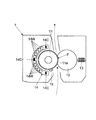
図3に示すように、本実施形態の定着部1は、加熱ローラー11、加圧ローラー12、付勢部材13、励磁コイル14、温度センサー15を含む。尚、加熱ローラー11と加圧ローラー12は、それぞれの軸線方向が平行となるように、回転可能に支持される。   As shown in FIG. 3, the fixing unit 1 of the present embodiment includes a heating roller 11, a pressure roller 12, an urging member 13, an excitation coil 14, and a temperature sensor 15. Note that the heating roller 11 and the pressure roller 12 are rotatably supported so that their axial directions are parallel to each other.

加熱ローラー11は、図3の紙面奥行き方向(用紙搬送方向と垂直な方向、用紙幅方向)を軸線方向とする。そして、加熱ローラー11は、励磁コイル14によって誘導加熱される。加熱ローラー11は、金属製の筒状の管の表面に、励磁コイル14からの磁束による誘導加熱作用によって発熱するニッケルのような金属の加熱ベルト11aを巻き付けたものである。尚、加熱ローラー11の管内部は、蓄熱性の材料で埋められていてもよい。尚、加熱ローラー11は上記の構成に限られず、誘導加熱されるものであればよい。   The heating roller 11 has the axial direction in the paper surface depth direction (direction perpendicular to the paper conveyance direction, paper width direction) in FIG. The heating roller 11 is induction heated by the exciting coil 14. The heating roller 11 is formed by winding a metal heating belt 11a such as nickel that generates heat by the induction heating action by the magnetic flux from the exciting coil 14 around the surface of a metal cylindrical tube. Note that the inside of the tube of the heating roller 11 may be filled with a heat storage material. Note that the heating roller 11 is not limited to the above-described configuration, and may be any one that is induction-heated.

そして、加熱ローラー11に対向して、加圧ローラー12が設けられる。加圧ローラー12の周面は弾性を有する。加圧ローラー12の周面の材料は、例えば、シリコンゴムである。そして、加圧ローラー12は、加熱ローラー11と圧接される。付勢部材13は、バネのような加圧ローラー12を加熱ローラー11に押しつける方向に付勢する部材である。この加熱ローラー11と加圧ローラー12の圧接により、定着のための定着ニップFが形成される。   A pressure roller 12 is provided to face the heating roller 11. The peripheral surface of the pressure roller 12 has elasticity. The material of the peripheral surface of the pressure roller 12 is, for example, silicon rubber. The pressure roller 12 is in pressure contact with the heating roller 11. The urging member 13 is a member that urges the pressure roller 12 such as a spring in a direction in which the pressure roller 12 is pressed against the heating roller 11. A fixing nip F for fixing is formed by the pressure contact between the heating roller 11 and the pressure roller 12.

定着部1に設けられる定着モーター16(図4参照)の駆動力が、加圧ローラー12に伝達される。これにより、加圧ローラー12が回転する。加圧ローラー12が回転すると、加圧ローラー12が当接している加熱ローラー11も従動して回転する。そして、加熱ローラー11と加圧ローラー12を回転させて定着ニップFに用紙Pを通過させる。これにより、トナー像が、加熱、加圧され、トナー像は用紙Pに定着する。尚、図3では用紙搬送方向を破線で図示している。   A driving force of a fixing motor 16 (see FIG. 4) provided in the fixing unit 1 is transmitted to the pressure roller 12. Thereby, the pressure roller 12 rotates. When the pressure roller 12 rotates, the heating roller 11 in contact with the pressure roller 12 is also driven to rotate. Then, the sheet P is passed through the fixing nip F by rotating the heating roller 11 and the pressure roller 12. As a result, the toner image is heated and pressurized, and the toner image is fixed on the paper P. In FIG. 3, the paper conveyance direction is indicated by broken lines.

次に、励磁コイル14を説明する。図3に示すように、加圧ローラー12が設けられる側と反対側に、加熱ローラー11に対向して、励磁コイル14が設けられる。そして、図3に示すように、励磁コイル14は、加熱ローラー11を周方向から見てハ字状になるように、加熱ローラー11の軸線方向に沿って電線14Wをかけ回したものである。   Next, the exciting coil 14 will be described. As shown in FIG. 3, an exciting coil 14 is provided on the side opposite to the side where the pressure roller 12 is provided so as to face the heating roller 11. As shown in FIG. 3, the exciting coil 14 is formed by winding the electric wire 14 </ b> W along the axial direction of the heating roller 11 so that the heating roller 11 is formed in a letter C shape when viewed from the circumferential direction.

励磁コイル14は、1本の電線14Wを複数回巻いたものである。電線14Wは、表面が絶縁体で被覆される。そして、電線14Wの両端を端子として、端子に電圧が印加される。これにより、電流が励磁コイル14に流れ、磁束が発生する。そして、励磁コイル14から発生した磁束は、加熱ローラー11の加熱ベルト11aに鎖交する。これにより、加熱ベルト11aは、渦電流によるジュール熱により温められる。この誘導加熱により、定着部1の急速加熱が可能である。   The exciting coil 14 is obtained by winding one electric wire 14W a plurality of times. The surface of the electric wire 14W is covered with an insulator. And a voltage is applied to a terminal by using both ends of the electric wire 14W as terminals. Thereby, an electric current flows into the exciting coil 14 and a magnetic flux is generated. The magnetic flux generated from the excitation coil 14 is linked to the heating belt 11 a of the heating roller 11. Thereby, the heating belt 11a is warmed by Joule heat caused by eddy current. By this induction heating, the fixing unit 1 can be rapidly heated.

そして、励磁コイル14の磁束により発熱する位置をずらし、満遍なく加熱ローラー11を温めるため、加熱ローラー11は回転する。又、加熱ローラー11の回転により、熱が加圧ローラー12にも伝導する。これにより、加圧ローラー12も温められる。尚、印刷開始時や印刷中に加熱ローラー11は誘導加熱される。一方、印刷ジョブと印刷ジョブの間や、省電力モードなどの画像形成を行っていない状態では、加熱ローラー11は誘導加熱されない。尚、電源投入時や省電力モードからの復帰時のウォームアップ処理のとき、加熱ローラー11は誘導加熱されてもよい。   Then, the heating roller 11 rotates in order to shift the position where heat is generated by the magnetic flux of the exciting coil 14 and warm the heating roller 11 evenly. Also, heat is conducted to the pressure roller 12 by the rotation of the heating roller 11. Thereby, the pressure roller 12 is also warmed. The heating roller 11 is induction-heated at the start of printing or during printing. On the other hand, the heating roller 11 is not induction-heated between print jobs or in a state where image formation such as a power saving mode is not performed. In addition, the heating roller 11 may be induction-heated at the time of warm-up processing when turning on the power or returning from the power saving mode.

又、励磁コイル14の内部には、3つのフェライトコア14Cが設けられる。図3に示すように、フェライトコア14Cは、加熱ローラー11の周面に沿うように、軸線方向からみて励磁コイル14の巻き線の中央と両端位置に設けられる。フェライトコア14Cは、励磁コイル14から生ずる磁束の拡散を防ぎ、効率よく磁束を加熱ベルト11aに鎖交させるためのものである。   In addition, three ferrite cores 14 </ b> C are provided inside the excitation coil 14. As shown in FIG. 3, the ferrite core 14 </ b> C is provided at the center and both end positions of the winding of the exciting coil 14 as viewed from the axial direction so as to follow the peripheral surface of the heating roller 11. The ferrite core 14 </ b> C is for preventing diffusion of the magnetic flux generated from the exciting coil 14 and efficiently linking the magnetic flux to the heating belt 11 a.

又、本実施形態の定着部1に、温度センサー15が設けられる。温度センサー15は、用紙Pの定着ニップFへの進入部分近傍に加熱ローラー11に接するように設けられる。言い換えると、温度センサー15は接触式である。そして、温度センサー15は、サーミスタを含み、加熱ローラー11(加熱ベルト11a)の温度によって、出力電圧が異なる。尚、加熱ローラー11の軸線方向の複数の位置の温度を検知するため、温度センサー15は、複数設けられてもよい。   Further, a temperature sensor 15 is provided in the fixing unit 1 of the present embodiment. The temperature sensor 15 is provided in contact with the heating roller 11 in the vicinity of the portion where the paper P enters the fixing nip F. In other words, the temperature sensor 15 is a contact type. The temperature sensor 15 includes a thermistor, and the output voltage varies depending on the temperature of the heating roller 11 (heating belt 11a). In addition, in order to detect the temperature of the several position of the axial direction of the heating roller 11, the temperature sensor 15 may be provided with two or more.

(定着部1のハードウェア構成)
次に、図4を用いて、実施形態に係る定着部1と誘導加熱に関する部分のハードウェア構成を説明する。図4は、定着部1と誘導加熱に関する部分のハードウェア構成を説明する図である。
(Hardware configuration of fixing unit 1)
Next, the hardware configuration of the fixing unit 1 and the portion related to induction heating according to the embodiment will be described with reference to FIG. FIG. 4 is a diagram for explaining the hardware configuration of the fixing unit 1 and a portion related to induction heating.

図4示すように、本実施形態の定着部1には、定着部1の加熱に関する制御を行う加熱制御部6が設けられる。加熱制御部6は、主制御部5から受ける目標電力指示S1を受けて加熱制御を行う。加熱制御部6は、CPU61や加熱の制御に関するデータやプログラムを記憶したメモリー62を含む。加熱制御部6内のCPU61が駆動回路部71を制御して誘導加熱による加熱ローラー11の温度制御を行う(詳細は後述)。   As shown in FIG. 4, the fixing unit 1 of the present embodiment is provided with a heating control unit 6 that performs control related to heating of the fixing unit 1. The heating control unit 6 receives the target power instruction S1 received from the main control unit 5 and performs heating control. The heating control unit 6 includes a CPU 61 and a memory 62 that stores data and programs related to heating control. The CPU 61 in the heating control unit 6 controls the drive circuit unit 71 to control the temperature of the heating roller 11 by induction heating (details will be described later).

尚、定着部1には、加熱ローラー11や加圧ローラー12を回転駆動させる定着モーター16が設けられる。加熱ローラー11を誘導加熱するときなど、主制御部5は、定着モーター16を回転させる。   The fixing unit 1 is provided with a fixing motor 16 that rotationally drives the heating roller 11 and the pressure roller 12. When the heating roller 11 is induction-heated, the main control unit 5 rotates the fixing motor 16.

図4に示すように、定着部1内では、励磁コイル14が設けられる。尚、励磁コイル14にはコンデンサ(不図示)が接続され、共振回路が構成される。そして、この励磁コイル14に電力供給を行う電源部7が設けられる。加熱制御部6は電源部7から励磁コイル14に供給される電力を制御する。   As shown in FIG. 4, an excitation coil 14 is provided in the fixing unit 1. Note that a capacitor (not shown) is connected to the excitation coil 14 to form a resonance circuit. And the power supply part 7 which supplies electric power to this exciting coil 14 is provided. The heating control unit 6 controls the power supplied from the power source unit 7 to the exciting coil 14.

ここで、図4を用いて、励磁コイル14への電力供給を説明する。まず、プリンター100(定着部1)の電源部7には、商用電源が接続される。言い換えると、商用電源から交流電力が電源部7に入力される。そして、電源部7には、励磁コイル14への電力供給のON/OFFを行う駆動回路部71が設けられる。駆動回路部71は、励磁コイル14への電力の供給のON/OFFを行うためのスイッチング素子72を含む。   Here, the power supply to the exciting coil 14 will be described with reference to FIG. First, a commercial power source is connected to the power source unit 7 of the printer 100 (fixing unit 1). In other words, AC power is input to the power supply unit 7 from a commercial power supply. The power supply unit 7 is provided with a drive circuit unit 71 that turns ON / OFF the power supply to the excitation coil 14. The drive circuit unit 71 includes a switching element 72 for turning on / off the supply of electric power to the exciting coil 14.

商用電源から供給された交流電力を変換せずに励磁コイル14に入力する場合、加熱制御部6は交流電圧波形の1周期中にスイッチング素子72をONするタイミング(位相)を調整することにより、励磁コイル14に供給する電力の大きさを制御する。   When the AC power supplied from the commercial power source is input to the exciting coil 14 without being converted, the heating control unit 6 adjusts the timing (phase) at which the switching element 72 is turned ON during one cycle of the AC voltage waveform. The magnitude of power supplied to the exciting coil 14 is controlled.

又、駆動回路部71は商用電源から供給された交流電力の周波数を変換し、一定電圧を出力するインバーターでもよい。周波数が高いほど励磁コイル14に電流は流れにくくなり、励磁コイル14とコンデンサーからなる共振回路の共振周波数に近づくほど励磁コイル14に大きな電流が流れる。そこで、駆動回路部71にインバーターを用いる場合、加熱制御部6は生成すべき励磁コイル14への印加電圧の周波数を駆動回路部71に指示して励磁コイル14に供給する電力の大きさを制御する。   The drive circuit unit 71 may be an inverter that converts the frequency of AC power supplied from a commercial power source and outputs a constant voltage. The higher the frequency, the less the current flows through the exciting coil 14, and the larger the current approaches the resonant frequency of the resonant circuit comprising the exciting coil 14 and the capacitor, the larger the current flows through the exciting coil 14. Therefore, when an inverter is used for the drive circuit unit 71, the heating control unit 6 controls the magnitude of the power supplied to the excitation coil 14 by instructing the drive circuit unit 71 the frequency of the applied voltage to the excitation coil 14 to be generated. To do.

又、駆動回路部71は、商用電源を整流、平滑して一定電圧を生成するコンバーターと、励磁コイル14へのコンバーターの出力の印加のON/OFFのスイッチングを行うスイッチング素子72で構成してもよい。この場合、加熱制御部6はスイッチング素子72のスイッチング周波数を制御して励磁コイル14に供給する電力の大きさを制御する。   Further, the drive circuit unit 71 may be composed of a converter that rectifies and smoothes the commercial power supply to generate a constant voltage, and a switching element 72 that performs ON / OFF switching of application of the converter output to the excitation coil 14. Good. In this case, the heating control unit 6 controls the switching frequency of the switching element 72 to control the amount of power supplied to the exciting coil 14.

このように、加熱制御部6は、駆動回路部71を制御して、励磁コイル14への電力供給のON/OFFや、励磁コイル14に投入する電力を制御できる。   As described above, the heating control unit 6 can control the drive circuit unit 71 to control ON / OFF of the power supply to the excitation coil 14 and the power supplied to the excitation coil 14.

そして、図4に示すように、本実施形態の定着部1には、温度センサー15が設けられる。温度センサー15の出力(電圧)は、主制御部5に入力される。そして、主制御部5は、記憶部52に記憶された温度センサー15の出力電圧に対応する温度のデータである温度検知用データD1を参照する。これにより、主制御部5は、加熱ローラー11の温度を認識する。主制御部5は加熱ローラー11の温度認識を予め定められた周期で行う。予め定められた周期は、百数十m秒〜数百m秒程度である。   As shown in FIG. 4, a temperature sensor 15 is provided in the fixing unit 1 of the present embodiment. The output (voltage) of the temperature sensor 15 is input to the main controller 5. Then, the main control unit 5 refers to temperature detection data D <b> 1 that is temperature data corresponding to the output voltage of the temperature sensor 15 stored in the storage unit 52. Thereby, the main control unit 5 recognizes the temperature of the heating roller 11. The main controller 5 recognizes the temperature of the heating roller 11 at a predetermined cycle. The predetermined period is about several hundreds of milliseconds to several hundreds of milliseconds.

又、主制御部5は、認識した温度に応じて、加熱制御部6に励磁コイル14の目標出力、言い換えると、励磁コイル14に投入すべき目標電力を示すデータ(目標電力指示S1)を送信する。主制御部5は、百数十ミリ秒〜数百m秒程度の周期で、加熱制御部6に向けて、目標電力を示すデータの送信を行う。   Further, the main control unit 5 transmits to the heating control unit 6 the target output of the excitation coil 14, that is, data indicating the target power to be input to the excitation coil 14 (target power instruction S1) according to the recognized temperature. To do. The main control unit 5 transmits data indicating the target power to the heating control unit 6 with a period of about several hundreds of milliseconds to several hundreds of milliseconds.

主制御部5は、加熱ローラー11の温度が低ければ低いほど、大きな目標電力を示す目標電力指示S1を加熱制御部6に与える。又、加熱ローラー11の温度が高く、定着制御温度に近ければ近いほど、主制御部5は、小さな目標電力を示す目標電力指示S1を加熱制御部6に与える。一方、加熱ローラー11の温度が定着制御温度を越えていれば、主制御部5は、目標電力を0とする目標電力指示S1を加熱制御部6に与える。従って、主制御部5は、励磁コイルに投入できる最大電力から0Wの範囲の何れかの値を示す目標電力指示S1を加熱制御部6に与える。尚、本実施形態の定着部1では、定着制御温度は170°C程度である。加熱ローラー11の温度に対する目標電力を示すデータは予め記憶部52に電力指示用データD2として記憶される。主制御部5は、電力指示用データD2を参照して、認識した温度に基づき、目標電力を定める。   The main control unit 5 gives the heating control unit 6 a target power instruction S1 indicating a larger target power as the temperature of the heating roller 11 is lower. Further, as the temperature of the heating roller 11 is higher and closer to the fixing control temperature, the main control unit 5 gives a target power instruction S1 indicating a small target power to the heating control unit 6. On the other hand, if the temperature of the heating roller 11 exceeds the fixing control temperature, the main control unit 5 gives a target power instruction S1 for setting the target power to 0 to the heating control unit 6. Accordingly, the main control unit 5 gives the heating control unit 6 a target power instruction S1 indicating any value in the range from the maximum power that can be supplied to the exciting coil to 0 W. In the fixing unit 1 of the present embodiment, the fixing control temperature is about 170 ° C. Data indicating the target power with respect to the temperature of the heating roller 11 is stored in advance in the storage unit 52 as power instruction data D2. The main control unit 5 refers to the power instruction data D2 and determines a target power based on the recognized temperature.

(加熱制御部6による加熱の基本的な流れ)
次に、図4、図5を用いて、加熱ローラー11の誘導加熱の基本的な流れを説明する。図5は加熱制御部6による加熱の基本的な流れを示すフローチャートである。
(Basic flow of heating by the heating controller 6)
Next, the basic flow of induction heating of the heating roller 11 will be described with reference to FIGS. FIG. 5 is a flowchart showing a basic flow of heating by the heating control unit 6.

図5のスタートは、加熱ローラー11の温度を定着制御温度とし、定着制御温度で維持するため、加熱制御部6が主制御部5から励磁コイル14への電力供給を行う旨の指示を受け、目標電力指示S1を受けた時点である。印刷のために加熱ローラー11を定着制御温度にまで熱して維持するとき、主制御部5は加熱ローラー11の誘導加熱を開始する指示や目標電力指示S1を加熱制御部6に与える。   In the start of FIG. 5, the heating control unit 6 receives an instruction to supply power to the exciting coil 14 from the main control unit 5 in order to set the temperature of the heating roller 11 as the fixing control temperature and maintain the fixing control temperature. This is the time when the target power instruction S1 is received. When the heating roller 11 is heated to the fixing control temperature and maintained for printing, the main control unit 5 gives an instruction to start the induction heating of the heating roller 11 and a target power instruction S1 to the heating control unit 6.

加熱制御部6は、主制御部5から指示された目標電力(消費電力)となるように、電源部7(駆動回路部71)を制御して、励磁コイル14に電力の供給を行う(ステップ♯11)。尚、加熱ローラー11の温度が定着制御温度を超えているなどの理由により、加熱制御部6は目標電力ゼロの指示を受けると、一時的に励磁コイル14への電力供給を停止させる。   The heating control unit 6 controls the power supply unit 7 (drive circuit unit 71) so that the target power (power consumption) instructed by the main control unit 5 is obtained, and supplies power to the excitation coil 14 (step). # 11). When the temperature of the heating roller 11 exceeds the fixing control temperature, the heating control unit 6 temporarily stops the power supply to the exciting coil 14 when receiving an instruction of zero target power.

そして、図4に示すように、定着部1には、励磁コイル14に供給される電力に関し、電圧検知センサー63と電流検知センサー64が設けられる。電圧検知センサー63と電流検知センサー64の出力は、加熱制御部6に入力される。加熱制御部6は、電圧検知センサー63と電流検知センサー64の出力に基づき、励磁コイル14に供給される電力の大きさを認識する(ステップ♯12)。   As shown in FIG. 4, the fixing unit 1 is provided with a voltage detection sensor 63 and a current detection sensor 64 for the power supplied to the excitation coil 14. Outputs of the voltage detection sensor 63 and the current detection sensor 64 are input to the heating control unit 6. The heating controller 6 recognizes the magnitude of the electric power supplied to the exciting coil 14 based on the outputs of the voltage detection sensor 63 and the current detection sensor 64 (step # 12).

加熱制御部6のメモリー62は、電圧検知センサー63と電流検知センサー64の出力に対応して、励磁コイル14への入力電圧値や入力電流値や入力電力を示すデータを記憶する。加熱制御部6は、電圧検知センサー63と電流検知センサー64の出力とこのデータを参照して、入力電力の大きさを認識する。   The memory 62 of the heating control unit 6 stores data indicating the input voltage value, the input current value, and the input power to the exciting coil 14 corresponding to the outputs of the voltage detection sensor 63 and the current detection sensor 64. The heating control unit 6 recognizes the magnitude of the input power with reference to the output of the voltage detection sensor 63 and the current detection sensor 64 and this data.

続いて、加熱制御部6は、フィードバック制御を行って、励磁コイル14の消費電力が目標電力と一致するように、駆動回路部71に励磁コイル14に供給する電力を調整させる(ステップ♯13)。言い換えると、加熱制御部6は、目標電力と、認識した励磁コイル14の消費電力に差分を埋めるように駆動回路部71を制御して、励磁コイル14に供給される電力を調整する。これにより、誤差等により励磁コイル14の消費電力が目標電力からずれても、励磁コイル14に供給される電力が調整される。   Subsequently, the heating control unit 6 performs feedback control to cause the drive circuit unit 71 to adjust the power supplied to the excitation coil 14 so that the power consumption of the excitation coil 14 matches the target power (step # 13). . In other words, the heating control unit 6 controls the drive circuit unit 71 so as to fill the difference between the target power and the recognized power consumption of the excitation coil 14 to adjust the power supplied to the excitation coil 14. Thereby, even if the power consumption of the exciting coil 14 deviates from the target power due to an error or the like, the power supplied to the exciting coil 14 is adjusted.

加熱制御部6は、励磁コイル14の消費電力が目標電力よりも小さければ、駆動回路部71を制御して励磁コイル14に供給する電力を増やす。一方、加熱制御部6は、励磁コイル14の消費電力が目標電力よりも大きければ、駆動回路部71を制御して励磁コイル14に供給する電力を減らす。メモリー62は、目標電力と認識した励磁コイル14の消費電力との差分の大きさに応じ、どのように駆動回路部71を制御するかを示すデータを記憶する。そして、加熱制御部6は、メモリー62に記憶されるデータに基づき、目標電力と認識した励磁コイル14の消費電力との差分の大きさに応じて、駆動回路部71を制御する。このように、加熱制御部6は、目標電力と認識した励磁コイル14に供給される電力が一致するように、駆動回路部71を制御する。   If the power consumption of the excitation coil 14 is smaller than the target power, the heating control unit 6 controls the drive circuit unit 71 to increase the power supplied to the excitation coil 14. On the other hand, if the power consumption of the excitation coil 14 is larger than the target power, the heating control unit 6 controls the drive circuit unit 71 to reduce the power supplied to the excitation coil 14. The memory 62 stores data indicating how to control the drive circuit unit 71 in accordance with the magnitude of the difference between the target power and the power consumption of the exciting coil 14 recognized. The heating control unit 6 controls the drive circuit unit 71 according to the magnitude of the difference between the target power and the power consumption of the exciting coil 14 recognized based on the data stored in the memory 62. In this way, the heating control unit 6 controls the drive circuit unit 71 so that the power supplied to the excitation coil 14 recognized as the target power matches.

又、加熱制御部6は、電圧検知センサー63と電流検知センサー64の出力に基づき、励磁コイル14に供給される電力に異常があるか否かを検知する(ステップ♯14)。言い換えると、加熱制御部6は励磁コイル14に供給される電圧や電流が予め定められた供給条件から外れているか否かを検知する。尚、励磁コイル14に供給される電力の異常は、プリンター100と同じコンセントに接続された機器の消費電力増大や、一時的なノイズや、タコ足配線などのような様々な要因により生じ得る。   The heating control unit 6 detects whether or not there is an abnormality in the power supplied to the exciting coil 14 based on the outputs of the voltage detection sensor 63 and the current detection sensor 64 (step # 14). In other words, the heating control unit 6 detects whether or not the voltage or current supplied to the exciting coil 14 is out of predetermined supply conditions. An abnormality in the power supplied to the exciting coil 14 may be caused by various factors such as an increase in power consumption of a device connected to the same outlet as the printer 100, temporary noise, and octopus wiring.

励磁コイル14に印加される電圧が予め定められた供給条件外のとき、加熱制御部6は電力異常と判断する。駆動回路部71が励磁コイル14に印加する電圧の大きさの定格が仕様上決まっているとする。そして、加熱制御部6は、仕様上の定格の電圧値に対し、電圧値が動作を保証できる電圧値の範囲として予め定められた電圧値範囲から外れた大きさとなると電力異常と判断する。言い換えると、加熱制御部6は、電源部7が励磁コイル14に印加する電圧の大きさを検知し、電圧値が予め定められた電圧値範囲に無いとき、電力異常と検知する。本実施形態のプリンター100では、加熱制御部6は電圧値が仕様上の定格の電圧の大きさに対し±10〜15%の範囲から外れると、電力異常と判断する。   When the voltage applied to the exciting coil 14 is outside a predetermined supply condition, the heating control unit 6 determines that the power is abnormal. It is assumed that the rating of the magnitude of the voltage applied to the exciting coil 14 by the drive circuit unit 71 is determined in the specification. The heating control unit 6 determines that the power is abnormal when the voltage value is out of a predetermined voltage value range as a voltage value range in which operation can be guaranteed with respect to the rated voltage value in the specification. In other words, the heating control unit 6 detects the magnitude of the voltage applied to the excitation coil 14 by the power supply unit 7 and detects that the power is abnormal when the voltage value is not within a predetermined voltage value range. In the printer 100 of the present embodiment, the heating control unit 6 determines that the power is abnormal when the voltage value is out of the range of ± 10 to 15% with respect to the rated voltage magnitude in the specification.

又、予め定められた供給条件は電流に対して定められてもよい。目標電力を励磁コイル14に供給するときの理想的な電流の大きさに対し、一定範囲外の電流が流れたとき、加熱制御部6は電流値の異常による電力異常と判断する。   Also, the predetermined supply condition may be determined for the current. When a current outside a certain range flows with respect to the ideal current when supplying the target power to the exciting coil 14, the heating control unit 6 determines that the power is abnormal due to an abnormal current value.

もし、電力異常があれば(ステップ♯14のYes)、励磁コイル14への電力供給を続けることは好ましくないので、加熱制御部6は、自発的に励磁コイル14への電力供給を停止させる(ステップ♯15)。言い換えると、加熱制御部6は励磁コイル14による誘導加熱を停止させる。   If there is a power abnormality (Yes in step # 14), it is not preferable to continue supplying power to the excitation coil 14, so the heating control unit 6 voluntarily stops power supply to the excitation coil 14 ( Step # 15). In other words, the heating control unit 6 stops the induction heating by the exciting coil 14.

更に、加熱制御部6は、電力異常に基づき、励磁コイル14への電力供給を停止した旨の停止通知S2を主制御部5に通知する(ステップ♯16)。これにより、主制御部5は電圧や電流の異常により、加熱制御部6が励磁コイル14への電力供給を停止させていることを認識できる。又、主制御部5は停止通知S2のあったこと、及び、停止通知S2を受けた時間を記憶部52に記憶させ、停止通知履歴D3として残す。   Furthermore, the heating control unit 6 notifies the main control unit 5 of a stop notification S2 indicating that the power supply to the exciting coil 14 is stopped based on the power abnormality (step # 16). Thereby, the main control part 5 can recognize that the heating control part 6 has stopped the electric power supply to the exciting coil 14 by abnormality of a voltage or an electric current. Further, the main control unit 5 stores the stop notification S2 and the time when the stop notification S2 is received in the storage unit 52, and leaves it as the stop notification history D3.

続いて、加熱制御部6は、励磁コイル14に印加する電圧の異常が回復して、電力異常が回復したか否かを確認する(ステップ♯17)。加熱制御部6は、電圧が予め定められた供給条件の範囲内になり、電力異常が回復するまで確認を続ける(ステップ♯17のNo→ステップ♯17)。   Subsequently, the heating control unit 6 confirms whether or not the abnormality of the voltage applied to the excitation coil 14 has been recovered and the abnormality of the power has been recovered (step # 17). The heating control unit 6 continues the confirmation until the voltage falls within a predetermined supply condition range and the power abnormality is recovered (No in step # 17 → step # 17).

一方、電力異常が回復したとき(ステップ♯17のYes)、加熱制御部6は、励磁コイル14への目標電力指示S1に基づく電力供給を再開する(ステップ♯18)。又、加熱制御部6は電力異常が回復し、励磁コイル14への電力供給を再開した旨の再開通知S3を主制御部5に通知する(ステップ♯19)。言い換えると、加熱制御部6は、電力異常が回復したことを認識すると励磁コイル14への電力供給を再開するとともに、再開通知S3を主制御部5に通知する。これにより、主制御部5は電圧や電流の異常が正常の範囲に回復し、加熱制御部6が励磁コイル14への電力供給を再開したことを認識できる。又、主制御部5は再開通知S3のあったこと、及び、再開通知S3を受けた時間を記憶部52に記憶させ、再開通知履歴D4として残す。   On the other hand, when the power abnormality is recovered (Yes in step # 17), the heating control unit 6 resumes the power supply based on the target power instruction S1 to the exciting coil 14 (step # 18). The heating control unit 6 notifies the main control unit 5 of a restart notification S3 indicating that the power abnormality has been recovered and the power supply to the exciting coil 14 has been restarted (step # 19). In other words, when the heating control unit 6 recognizes that the power abnormality has been recovered, the heating control unit 6 restarts the power supply to the exciting coil 14 and notifies the main control unit 5 of the restart notification S3. As a result, the main control unit 5 can recognize that the abnormality of the voltage or current has been restored to the normal range, and the heating control unit 6 has resumed the supply of power to the excitation coil 14. Further, the main control unit 5 stores the restart notification S3 and the time when the restart notification S3 was received in the storage unit 52 and leaves it as the restart notification history D4.

そして、電力異常が無いとき(ステップ♯14のNo)や、ステップ♯19の後、加熱制御部6は、主制御部5から誘導加熱停止の指示を受けたか否かを確認する(ステップ♯110)。印刷完了などのような場合、主制御部5は加熱制御部6に対して誘導加熱停止の指示を与える。言い換えると、加熱ローラー11を定着制御温度で温める必要がなくなると、主制御部5は励磁コイル14への電力供給停止の指示を加熱制御部6に与える。   Then, when there is no power abnormality (No in Step # 14) or after Step # 19, the heating control unit 6 confirms whether or not an induction heating stop instruction has been received from the main control unit 5 (Step # 110). ). When printing is completed, the main control unit 5 gives an instruction to stop the induction heating to the heating control unit 6. In other words, when it is no longer necessary to heat the heating roller 11 at the fixing control temperature, the main control unit 5 gives the heating control unit 6 an instruction to stop power supply to the exciting coil 14.

加熱制御部6が主制御部5から誘導加熱停止の指示を受けたとき(ステップ♯110のYes)、加熱制御部6は励磁コイル14への電力供給を停止する(ステップ♯111→エンド)。そして、印刷ジョブを開始するときのような場合、再び本フローが開始される。尚、本説明では、印刷完了にともない、誘導加熱を停止する例を説明するが、通常モードにあるとき(省電力モード移行前)、主制御部5は加熱制御部6に励磁コイル14への電力供給を断続的に行わせ、加熱ローラー11の温度を定着制御温度で維持するようにしてもよい。   When the heating control unit 6 receives an instruction to stop induction heating from the main control unit 5 (Yes in Step # 110), the heating control unit 6 stops supplying power to the exciting coil 14 (Step # 111 → End). Then, in the case of starting a print job, this flow is started again. In this description, an example in which induction heating is stopped upon completion of printing will be described. However, when in the normal mode (before the transition to the power saving mode), the main control unit 5 connects the heating control unit 6 to the excitation coil 14. The power supply may be intermittently performed so that the temperature of the heating roller 11 is maintained at the fixing control temperature.

一方、加熱制御部6が主制御部5から誘導加熱停止の指示を受けていないとき(ステップ♯110のNo)、加熱制御部6は、主制御部5から新たな目標電力指示S1を受ける(ステップ♯112)。そして、フローはステップ♯11に戻る。   On the other hand, when the heating control unit 6 has not received an instruction to stop induction heating from the main control unit 5 (No in step # 110), the heating control unit 6 receives a new target power instruction S1 from the main control unit 5 ( Step # 112). Then, the flow returns to step # 11.

(温度異常の検知と報知)
次に、図6を用いて、本実施形態のプリンター100での主制御部5による温度異常の検知と、異常の報知を説明する。図6は、温度異常の検知と、異常の報知の流れを示すフローチャートである。
(Temperature abnormality detection and notification)
Next, temperature abnormality detection and abnormality notification by the main control unit 5 in the printer 100 of the present embodiment will be described with reference to FIG. FIG. 6 is a flowchart showing a flow of temperature abnormality detection and abnormality notification.

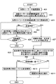
本実施形態の主制御部5は温度センサー15の出力に基づき、加熱ローラー11の温度を認識する。そして、主制御部5は目標電力指示S1を加熱制御部6に与えているのに、加熱ローラー11の温度が予め定められた温度帯から外れていたり、加熱ローラー11の温度が高すぎたり、低すぎたりすると、加熱ローラー11の温度異常と検知する。そこで、図6を用いて、温度異常の検知と、異常の報知の流れを説明する。
The main control unit 5 of the present embodiment recognizes the temperature of the heating roller 11 based on the output of the temperature sensor 15. And although the main control part 5 is giving the target electric power instruction | command S1 to the heating control part 6, the temperature of the heating roller 11 has remove | deviated from the predetermined temperature range, the temperature of the heating roller 11 is too high, If it is too low, it is detected that the temperature of the heating roller 11 is abnormal. Therefore, with reference to FIG. 6, illustrating a temperature abnormality detection, the flow of notification of the abnormality.

まず、図6のスタートは、印刷の開始時などに、主制御部5が加熱ローラー11の温度を定着制御温度に到達させるため、励磁コイル14への電力供給を開始する時点である。   First, the start of FIG. 6 is a time when the main control unit 5 starts supplying power to the exciting coil 14 so that the temperature of the heating roller 11 reaches the fixing control temperature at the start of printing.

尚、本フロー中、主制御部5は図5を用いて説明したように、加熱制御部6から主制御部5に対し、励磁コイル14への電力供給の状況に応じて停止通知S2や再開通知S3がなされ、主制御部5はこれらの通知を受信する。   During this flow, as described with reference to FIG. 5, the main control unit 5 notifies the main control unit 5 from the heating control unit 6 to the stop notification S <b> 2 or the restart according to the power supply status to the exciting coil 14. Notification S3 is made, and the main control unit 5 receives these notifications.

加熱ローラー11の温度を定着制御温度にまで誘導加熱するとき、まず、主制御部5は、温度センサー15の出力に基づき、加熱ローラー11の温度を認識する(ステップ♯21)。そして、主制御部5は認識した温度に基づき、加熱ローラー11を定着制御温度にまで誘導加熱するのに必要な電力を求める(ステップ♯22)。そして、主制御部5は求めた電力に基づき目標電力を加熱制御部6に指示し、加熱ローラー11を定着制御温度にまで誘導加熱させる(ステップ♯23)。主制御部5は、認識した温度が定着制御温度よりも一定温度以上低ければ、励磁コイル14に投入できる最大電力を示す目標電力指示S1を加熱制御部6に与える。又、主制御部5は、認識した温度が定着制御温度よりも一定温度以上であり、定着制御温度未満であれば、励磁コイル14に投入できる最大電力以下であるが、温度が低いほど大きい電力を示す目標電力指示S1を加熱制御部6に与える。   When induction heating the temperature of the heating roller 11 to the fixing control temperature, first, the main control unit 5 recognizes the temperature of the heating roller 11 based on the output of the temperature sensor 15 (step # 21). Based on the recognized temperature, the main control unit 5 obtains electric power necessary for induction heating the heating roller 11 to the fixing control temperature (step # 22). Then, the main control unit 5 instructs the heating control unit 6 on the target power based on the obtained power, and causes the heating roller 11 to be inductively heated to the fixing control temperature (step # 23). If the recognized temperature is lower than the fixing control temperature by a certain temperature or more, the main control unit 5 gives a target power instruction S1 indicating the maximum power that can be supplied to the exciting coil 14 to the heating control unit 6. In addition, the main control unit 5 is less than the maximum power that can be supplied to the exciting coil 14 if the recognized temperature is equal to or higher than the fixing control temperature and lower than the fixing control temperature. Is provided to the heating control unit 6.

加熱ローラー11の温度が室温程度まで冷えている状態から定着制御温度にまで加熱ローラー11を誘導加熱する場合、加熱ローラー11を定着制御温度にまで温めるのに要する電力は、大きくなる。一方、プリンター100がリセットされた場合など、ある程度、加熱ローラー11が暖まっている場合には、加熱ローラー11を定着制御温度にまで温めるのに要する電力は、小さくなる   When the heating roller 11 is induction-heated from the state where the temperature of the heating roller 11 is cooled to about room temperature to the fixing control temperature, the electric power required to warm the heating roller 11 to the fixing control temperature is increased. On the other hand, when the heating roller 11 is warmed to some extent, such as when the printer 100 is reset, the power required to warm the heating roller 11 to the fixing control temperature is small.

そして、主制御部5は温度センサー15の出力に基づき、定着制御温度を維持するように誘導加熱された加熱ローラー11に、温度異常が生じているか否かを確認する(ステップ♯24)。本実施形態のプリンター100では、定着制御温度を170°Cとして、フィードバック制御を行いつつ温度維持制御を行うと、加熱ローラー11の温度は実質的に、160〜180°C程度の範囲で維持される。   Based on the output of the temperature sensor 15, the main control unit 5 checks whether or not a temperature abnormality has occurred in the heating roller 11 that has been induction-heated so as to maintain the fixing control temperature (step # 24). In the printer 100 of this embodiment, when the fixing control temperature is set to 170 ° C. and the temperature maintenance control is performed while performing feedback control, the temperature of the heating roller 11 is substantially maintained in a range of about 160 to 180 ° C. The

そこで、加熱ローラー11の温度を定着制御温度で維持しようとしているとき、主制御部5は加熱ローラー11の温度が室温〜100°C程度の範囲(異常温度範囲)になると、温度異常と認識する。言い換えると、定着制御温度での温度維持中、主制御部5は加熱ローラー11の温度が異常温度範囲になると温度異常と認識する。尚、定着制御温度よりも高温側についても、異常温度範囲が設定されてもよい。例えば、250°C以上を異常温度範囲と設定することができるが、プリンター100に用いる部材との兼ね合いにより適宜決定すればよい。   Therefore, when trying to maintain the temperature of the heating roller 11 at the fixing control temperature, the main control unit 5 recognizes that the temperature is abnormal when the temperature of the heating roller 11 is in the range of about room temperature to 100 ° C. (abnormal temperature range). . In other words, while maintaining the temperature at the fixing control temperature, the main control unit 5 recognizes that the temperature of the heating roller 11 is abnormal when the temperature of the heating roller 11 falls within the abnormal temperature range. Note that the abnormal temperature range may also be set for a temperature higher than the fixing control temperature. For example, 250 ° C. or more can be set as the abnormal temperature range, but may be determined as appropriate depending on the balance with the member used in the printer 100.

もし、温度異常が発生していなければ(ステップ♯24のNo)、主制御部5は加熱ローラー11の温度認識と目標電力指示S1を行って、加熱ローラー11の温度を定着制御温度で維持する(ステップ♯25)。   If no temperature abnormality has occurred (No in step # 24), the main controller 5 performs temperature recognition of the heating roller 11 and target power instruction S1, and maintains the temperature of the heating roller 11 at the fixing control temperature. (Step # 25).

そして、主制御部5は加熱ローラー11の温度を定着制御温度で維持する温度維持制御を終了すべきか否かを確認する(ステップ♯26)。本実施形態のプリンター100では、主制御部5は、印刷が完了したとき温度維持制御を終了すると判断する。温度維持制御を終了すべきであれば、本フローは終了する。一方、まだ印刷が継続されるなどのように、温度維持制御を継続すべきであれば、フローはステップ♯24に戻る。   Then, the main control unit 5 checks whether or not the temperature maintenance control for maintaining the temperature of the heating roller 11 at the fixing control temperature should be terminated (step # 26). In the printer 100 of this embodiment, the main control unit 5 determines that the temperature maintenance control is to be terminated when printing is completed. If the temperature maintenance control is to be ended, this flow ends. On the other hand, if the temperature maintenance control is to be continued such that printing is still continued, the flow returns to step # 24.

一方、温度維持制御を行っているのに加熱ローラー11の温度が100°C以下になった場合などのように、温度異常が生ずれば(ステップ♯24のYes)、主制御部5は画像形成部4や定着部1や第2搬送部3cや第1搬送部3bや給紙部3aによる印刷を停止させる(ステップ♯27)。   On the other hand, if a temperature abnormality occurs, such as when the temperature of the heating roller 11 becomes 100 ° C. or less even though the temperature maintenance control is performed (Yes in step # 24), the main control unit 5 displays the image. Printing by the forming unit 4, the fixing unit 1, the second transport unit 3c, the first transport unit 3b, and the paper feed unit 3a is stopped (step # 27).

更に、主制御部5は加熱制御部6との通信履歴に基づき、温度異常が誘導加熱の停止に基づくか否かを判断する(ステップ♯28)。言い換えると、主制御部5は加熱制御部6から受けた停止通知S2の通信履歴である停止通知履歴D3と再開通知S3の通信履歴である再開通知履歴D4を参照し、温度異常が励磁コイル14に供給する電力の異常に基づくものか否かを判断する。このように、本実施形態のプリンター100では、主制御部5は、励磁コイル14への電力供給が一時的に停止し、加熱制御部6から停止通知S2を受けても、温度異常を認識するまで画像形成部4や定着部1には、印刷動作を継続させる。   Further, main controller 5 determines whether or not the temperature abnormality is based on the stop of induction heating based on the communication history with heating controller 6 (step # 28). In other words, the main control unit 5 refers to the stop notification history D3 that is the communication history of the stop notification S2 received from the heating control unit 6 and the restart notification history D4 that is the communication history of the restart notification S3. It is determined whether or not the power supply is based on an abnormality in the power supplied to. As described above, in the printer 100 of the present embodiment, the main control unit 5 recognizes the temperature abnormality even when the power supply to the excitation coil 14 is temporarily stopped and the stop notification S2 is received from the heating control unit 6. Until the image forming unit 4 and the fixing unit 1, the printing operation is continued.

プリンター100に入力される電力の異常や、電源部7の回路における異常により、加熱制御部6の判断により励磁コイル14への電力供給が停止されていれば、加熱ローラー11の温度は次第に低下してゆく。そこで、主制御部5は電源系統の異常により加熱ローラー11の温度低下が生じたか否かを判断する。   If the power supply to the exciting coil 14 is stopped by the determination of the heating control unit 6 due to an abnormality in the power input to the printer 100 or an abnormality in the circuit of the power supply unit 7, the temperature of the heating roller 11 gradually decreases. Go. Therefore, the main control unit 5 determines whether or not the temperature of the heating roller 11 has decreased due to an abnormality in the power supply system.

具体的には、主制御部5は、誘導加熱の開始から単位時間あたりの停止通知S2の回数が予め定められた回数を超えていることや、誘導加熱を開始してからの間、加熱制御部6から停止通知S2を受けてから再開通知S3を受けるまでの時間が予め定められた時間を超えていることに基づき、温度異常が誘導加熱停止に基づくと判断する。単位時間あたりの停止通知S2の回数や、予め定められた時間は誘導加熱停止時の加熱ローラー11の温度低下の程度を勘案して適宜定めることができる。
Specifically, the main control unit 5 performs the heating control after the number of times of the stop notification S2 per unit time from the start of the induction heating exceeds a predetermined number or after the induction heating is started. Based on the fact that the time from receipt of the stop notification S2 from the unit 6 to the receipt of the resume notification S3 exceeds a predetermined time, it is determined that the temperature abnormality is based on induction heating stop. The number of stop notifications S2 per unit time and a predetermined time can be appropriately determined in consideration of the degree of temperature drop of the heating roller 11 when induction heating is stopped.

一方、主制御部5は、再開通知S3から停止通知S2を受けること無く予め定められた猶予時間が経過してから温度異常を認識したとき、温度異常が誘導加熱停止に基づかないと判断する。これは、励磁コイル14への電力供給再開されてからの時間が経過しているので、温度異常は励磁コイル14に電力を供給する回路や系統の異常を要因としないと認められるからである。尚、予め定められた猶予時間も、誘導加熱停止時の加熱ローラー11の温度低下の程度を勘案して適宜定めることができる。   On the other hand, the main control unit 5 determines that the temperature abnormality is not based on the induction heating stop when the temperature abnormality is recognized after a predetermined grace period has elapsed without receiving the stop notification S2 from the restart notification S3. This is because it has been recognized that the temperature abnormality has not been caused by an abnormality in the circuit or system supplying power to the exciting coil 14 since the time since the power supply to the exciting coil 14 was resumed. In addition, the predetermined grace time can also be appropriately determined in consideration of the degree of temperature drop of the heating roller 11 when induction heating is stopped.

もし、主制御部5は温度異常が誘導加熱の停止に基づくと判断したとき(ステップ♯29のYes)、操作パネル2に電源異常が発生している旨を報知させる(ステップ♯210)。   If the main control unit 5 determines that the temperature abnormality is based on the stop of induction heating (Yes in step # 29), the main control unit 5 notifies the operation panel 2 that a power supply abnormality has occurred (step # 210).

一方、主制御部5は温度異常が誘導加熱の停止に基づくものではないと判断したとき(ステップ♯29のNo)、励磁コイル14への電力供給に異常はなく、定着部1の温度センサー15などの異常と考えられる。そこで、温度異常が誘導加熱の停止に基づくものではないと判断したとき、主制御部5は、操作パネル2に定着部1の異常を報知させる(ステップ♯211)。   On the other hand, when the main controller 5 determines that the temperature abnormality is not based on the stop of induction heating (No in step # 29), there is no abnormality in the power supply to the exciting coil 14, and the temperature sensor 15 of the fixing unit 1 It is considered abnormal. Thus, when determining that the temperature abnormality is not based on the induction heating stop, the main control unit 5 causes the operation panel 2 to notify the abnormality of the fixing unit 1 (step # 211).

このようにして、本実施形態の画像形成装置(プリンター100)は、トナー像を形成し、用紙Pに転写する画像形成部4と、加熱回転体(加熱ローラー11)と、加熱回転体に圧接して定着ニップFを形成する加圧回転体(加圧ローラー12)と、加熱回転体を誘導加熱するための励磁コイル14と、加熱回転体の温度を検知するための温度検知体(温度センサー15)を含み、定着ニップFにトナー像が転写された用紙Pを通過させてトナー像を用紙Pに定着させる定着部1と、温度検知体の出力に基づき加熱回転体の温度を認識し、加熱回転体の温度を定着に適した温度である定着制御温度で維持するとき、予め定められた温度異常範囲となる温度異常を認識すると画像形成部4と定着部1による印刷動作を停止させる主制御部5と、主制御部5が温度異常を認識したときに異常報知を行う報知部(操作パネル2)と、励磁コイル14に電力を供給する電源部7と、電源部7から励磁コイル14への電力供給を制御するとともに、励磁コイル14への供給電力を検知し、予め定められた供給条件から外れると励磁コイル14への供給電力の異常である電力異常を検知する加熱制御部6と、を含み、加熱制御部6は、励磁コイル14への電力供給制御を行っている状態で電力異常を検知したとき、電力供給を停止して誘導加熱を停止し、電力異常により誘導加熱停止を行った旨の停止通知S2を主制御部5に通知し、主制御部5は、加熱制御部6からの停止通知S2の履歴に基づき、温度異常が誘導加熱停止に基づくか否かを判断し、誘導加熱停止に基づくと判断したとき、報知部(操作パネル2)に電源異常を報知させ、誘導加熱停止に基づかないと判断したとき、報知部に定着部1の異常を報知させる。   In this way, the image forming apparatus (printer 100) of the present embodiment forms a toner image and transfers it onto the paper P, the heating rotating body (heating roller 11), and the heating rotating body. A pressure rotator (pressure roller 12) that forms the fixing nip F, an excitation coil 14 for induction heating the heating rotator, and a temperature detector (temperature sensor) for detecting the temperature of the heating rotator. 15), the fixing unit 1 that passes the paper P on which the toner image is transferred to the fixing nip F and fixes the toner image on the paper P, and the temperature of the heating rotator based on the output of the temperature detector, When the temperature of the heating rotator is maintained at the fixing control temperature, which is a temperature suitable for fixing, when the temperature abnormality within the predetermined temperature abnormality range is recognized, the printing operation by the image forming unit 4 and the fixing unit 1 is stopped. A control unit 5; Control part 5 controls power supply unit 7 that supplies power to excitation coil 14 and power supply unit 7 that supplies power to excitation coil 14 for notifying abnormality when control unit 5 recognizes a temperature abnormality (operation panel 2). And a heating control unit 6 that detects the power supplied to the exciting coil 14 and detects a power abnormality that is an abnormality in the power supplied to the exciting coil 14 when it deviates from a predetermined supply condition. When the power supply control to the exciting coil 14 is detected, the unit 6 stops the power supply, stops the induction heating, and notifies that the induction heating is stopped due to the power abnormality. S2 is notified to the main control unit 5, and the main control unit 5 determines whether the temperature abnormality is based on the induction heating stop based on the history of the stop notification S2 from the heating control unit 6, and based on the induction heating stop. When it is judged Parts (Operation Panel 2) to notify power failure, when it is determined not based on the induction heating is stopped, thereby informing the abnormality of the fixing unit 1 to the notification unit.

これにより、温度異常が生じた原因が区別されたうえで報知がなされる。従って、使用者やサービスマンは、異常の原因の判別を容易に行うことができる。そのため、電源系統に異常があるのに定着部1の交換を行うことや、温度検知体(温度センサー15)や励磁コイル14といった定着部1の部材に異常があるのに電源系統の点検を行うような無駄な作業を無くすことができる。   As a result, the cause of the occurrence of the temperature abnormality is identified and the notification is made. Therefore, the user or service person can easily determine the cause of the abnormality. Therefore, replacement of the fixing unit 1 is performed even though there is an abnormality in the power supply system, or the power supply system is inspected even if there is an abnormality in the members of the fixing unit 1 such as the temperature detection body (temperature sensor 15) and the excitation coil 14. Such useless work can be eliminated.

又、加熱制御部6は、電力異常が回復したことを認識すると励磁コイル14への電力供給を再開するとともに、励磁コイル14への電力供給を再開した旨の再開通知S3を主制御部5に通知する。これにより、励磁コイル14に供給する電圧、電流の異常が解消されたことを主制御部5は、認識することができる。従って、電圧、電流の異常が解消されてから温度異常を認識しても、温度異常は、励磁コイル14に供給する電圧、電流の異常に基づかないと判別することができる。   When the heating control unit 6 recognizes that the power abnormality has been recovered, the heating control unit 6 restarts the power supply to the excitation coil 14 and also notifies the main control unit 5 of the restart notification S3 to the effect that the power supply to the excitation coil 14 has been restarted. Notice. Thereby, the main controller 5 can recognize that the abnormality of the voltage and current supplied to the exciting coil 14 has been eliminated. Therefore, even if the temperature abnormality is recognized after the abnormality of the voltage and current is resolved, it can be determined that the temperature abnormality is not based on the abnormality of the voltage and current supplied to the exciting coil 14.

又、主制御部5は、単位時間あたりの停止通知S2の回数が予め定められた回数を超えていることと、加熱制御部6から停止通知S2を受けてから再開通知S3を受けるまでの時間が予め定められた時間を超えていることの何れか一方、又は、両方に該当しているとき、温度異常が誘導加熱停止に基づくと判断する。これにより、励磁コイル14に電力を供給する電源系統に異常がある可能性が高い場合、電源の異常が報知される。従って、正確に温度異常が生じた原因を報知することができる。
Further, the main control unit 5 determines that the number of stop notifications S2 per unit time exceeds a predetermined number of times, and the time from receiving the stop notification S2 from the heating control unit 6 to receiving the restart notification S3. Is determined to correspond to one or both of exceeding a predetermined time, it is determined that the temperature abnormality is based on induction heating stop. Thereby, when there is a high possibility that there is an abnormality in the power supply system that supplies power to the exciting coil 14, the abnormality of the power supply is notified. Therefore, the cause of the temperature abnormality can be notified accurately.

又、主制御部5は、再開通知S3から停止通知S2を受けること無く予め定められた猶予時間が経過してから温度異常を認識したとき、報知部(操作パネル2)に定着部1の異常を報知させる。これにより、一時的な電圧、電流に異常から回復し、励磁コイル14に正常な電力が供給されている場合、電源系統に異常があるという判断はなされない。従って、正確に温度異常の原因を判別することができる。   Further, when the main control unit 5 recognizes the temperature abnormality after the predetermined grace time has elapsed without receiving the stop notification S2 from the restart notification S3, the main control unit 5 notifies the abnormality (fixing unit 1) to the notification unit (operation panel 2). To let you know. Thus, when the temporary voltage and current are recovered from the abnormality and normal power is supplied to the exciting coil 14, it is not determined that the power supply system is abnormal. Therefore, the cause of the temperature abnormality can be accurately determined.

又、主制御部5は、加熱制御部6から停止通知S2を受けても、温度異常を認識するまで画像形成部4と定着部1には、印刷動作を継続させる。これにより、励磁コイル14に印加する電圧や電流に異常があっても、印刷は、直ちに停止されない。従って、一時的な電圧ドロップやノイズにより、電圧や電流に異常が生じても、印刷は継続される。そのため、一時的な電圧や電流の異常が生ずるごとに、使用者は、印刷のやり直しをしなくて済む。   Further, even when the main control unit 5 receives the stop notification S2 from the heating control unit 6, the image forming unit 4 and the fixing unit 1 continue the printing operation until the temperature abnormality is recognized. Thereby, even if there is an abnormality in the voltage or current applied to the exciting coil 14, printing is not immediately stopped. Therefore, printing is continued even if an abnormality occurs in voltage or current due to temporary voltage drop or noise. Therefore, each time a temporary voltage or current abnormality occurs, the user does not have to reprint.

又、主制御部5は、認識した温度に基づき、定着制御温度の維持に必要な電力を求め、求めた電力に基づき励磁コイル14に供給すべき電力を加熱制御部6に指示し、加熱制御部6は、主制御部5からの指示に基づき、電源部7から励磁コイル14に供給される電力を制御する。これにより、加熱制御部6が行うべき処理が少なくなり、緻密に、迅速に電源部7から励磁コイル14に供給される電力を制御することができる。   Further, the main control unit 5 obtains electric power necessary for maintaining the fixing control temperature based on the recognized temperature, and instructs the heating control unit 6 of electric power to be supplied to the exciting coil 14 based on the obtained electric power. The unit 6 controls the power supplied from the power supply unit 7 to the exciting coil 14 based on an instruction from the main control unit 5. Thereby, the process which the heating control part 6 should perform decreases, and the electric power supplied to the exciting coil 14 from the power supply part 7 can be controlled precisely and rapidly.

又、加熱制御部6は、電源部7が励磁コイル14に印加する電圧の大きさを検知し、電圧の大きさが予め定められた電圧値範囲内に無いとき、電力異常と検知する。これにより、定着を行う上で性能的に保証できないような電圧値のとき、電力異常として励磁コイル14による加熱を停止させることができる。   Further, the heating control unit 6 detects the magnitude of the voltage applied to the exciting coil 14 by the power supply unit 7, and detects that the power is abnormal when the magnitude of the voltage is not within a predetermined voltage value range. As a result, when the voltage value cannot be guaranteed in terms of fixing, heating by the exciting coil 14 can be stopped as a power abnormality.

以上、本発明の実施形態につき説明したが、本発明の範囲は、これに限定されるものでは、なく、発明の主旨を逸脱しない範囲で種々の変更を加えて実施することができる。   Although the embodiments of the present invention have been described above, the scope of the present invention is not limited to these embodiments, and various modifications can be made without departing from the spirit of the invention.

本発明は、誘導加熱方式の定着装置を有する画像形成装置に利用可能である。   The present invention can be used for an image forming apparatus having an induction heating type fixing device.

100 プリンター(画像形成装置) 1 定着部
11 加熱ローラー(加熱回転体) 12 加圧ローラー(加圧回転体)
14 励磁コイル 15 温度センサー(温度検知体)
2 操作パネル(報知部) 4 画像形成部
5 主制御部 6 加熱制御部
7 電源部 S1 目標電力指示
S2 停止通知 S3 再開通知
F 定着ニップ P 用紙
DESCRIPTION OF SYMBOLS 100 Printer (image forming apparatus) 1 Fixing part 11 Heating roller (heating rotary body) 12 Pressure roller (pressing rotary body)
14 Excitation coil 15 Temperature sensor (temperature detector)
2 Operation panel (notification unit) 4 Image forming unit 5 Main control unit 6 Heating control unit 7 Power supply unit S1 Target power instruction S2 Stop notification S3 Restart notification F Fixing nip P Paper

Claims (7)

トナー像を形成し、用紙に転写する画像形成部と、
加熱回転体と、加熱回転体に圧接して定着ニップを形成する加圧回転体と、前記加熱回転体を誘導加熱するための励磁コイルと、前記加熱回転体の温度を検知するための温度検知体を含み、前記定着ニップにトナー像が転写された用紙を通過させてトナー像を用紙に定着させる定着部と、
前記温度検知体の出力に基づき温度を認識し、前記加熱回転体の温度を定着に適した温度である定着制御温度で維持するとき、予め定められた温度異常範囲となる温度異常を認識すると前記画像形成部と前記定着部による印刷動作を停止させる主制御部と、
前記主制御部が前記温度異常を認識したときに異常報知を行う報知部と、
前記励磁コイルに電力を供給する電源部と、
前記電源部から前記励磁コイルへの電力供給を制御するとともに、前記励磁コイルへの供給電力を検知し、予め定められた供給条件から外れると前記励磁コイルへの供給電力の異常である電力異常を検知する加熱制御部と、を含み、
前記加熱制御部は、前記励磁コイルへの電力供給制御を行っている状態で前記電力異常を検知したとき、電力供給を停止して前記誘導加熱を停止し、前記電力異常により前記誘導加熱停止を行った旨の停止通知を前記主制御部に通知し、
前記主制御部は、前記加熱制御部からの前記停止通知の履歴に基づき、前記温度異常が誘導加熱停止に基づくか否かを判断し、前記誘導加熱停止に基づくと判断したとき、前記報知部に電源異常を報知させ、前記誘導加熱停止に基づかないと判断したとき、前記報知部に前記定着部の異常を報知させることを特徴とする画像形成装置。
An image forming unit that forms a toner image and transfers the toner image to a sheet;
A heating rotator, a pressure rotator that presses against the heating rotator to form a fixing nip, an excitation coil for induction heating the heating rotator, and a temperature detection for detecting the temperature of the heating rotator A fixing unit that includes a body and passes the sheet on which the toner image is transferred to the fixing nip to fix the toner image on the sheet;
When recognizing the temperature based on the output of the temperature detection body and maintaining the temperature of the heating rotator at a fixing control temperature that is a temperature suitable for fixing, if a temperature abnormality that falls within a predetermined temperature abnormality range is recognized, A main control unit for stopping a printing operation by the image forming unit and the fixing unit;
An informing unit for informing an abnormality when the main control unit recognizes the temperature abnormality;
A power supply for supplying power to the excitation coil;
While controlling the power supply from the power supply unit to the excitation coil, the power supply to the excitation coil is detected, and if the power supply unit is out of a predetermined supply condition, a power abnormality that is an abnormality in the power supply to the excitation coil A heating control unit to detect,
When the heating control unit detects the power abnormality while performing power supply control to the excitation coil, the heating control unit stops power supply to stop the induction heating, and stops the induction heating due to the power abnormality. Notifying the main control unit of a stop notification to the effect that
The main control unit determines whether the temperature abnormality is based on induction heating stop based on a history of the stop notification from the heating control unit, and determines that the temperature abnormality is based on the induction heating stop, the notification unit An image forming apparatus characterized by causing the notification unit to notify the fixing unit of an abnormality when it is determined that the abnormality is not based on the induction heating stop.
前記加熱制御部は、前記電力異常が回復したことを認識すると前記励磁コイルへの電力供給を再開するとともに、前記励磁コイルへの電力供給を再開した旨の再開通知を前記主制御部に通知することを特徴とする請求項1に記載の画像形成装置。   When the heating control unit recognizes that the power abnormality has been recovered, the heating control unit restarts the power supply to the excitation coil and notifies the main control unit of a restart notification to the effect that the power supply to the excitation coil has been restarted. The image forming apparatus according to claim 1. 前記主制御部は、単位時間あたりの前記停止通知の回数が予め定められた回数を超えていることと、前記加熱制御部から前記停止通知を受けてから前記再開通知を受けるまでの時間が予め定められた時間を超えていることの何れか一方、又は、両方に該当しているとき、前記温度異常が前記誘導加熱停止に基づくと判断することを特徴とする請求項2に記載の画像形成装置。
The main control unit is configured such that the number of times of the stop notification per unit time exceeds a predetermined number of times, and the time from when the stop notification is received from the heating control unit until the restart notification is received in advance. 3. The image formation according to claim 2, wherein the temperature abnormality is determined to be based on the induction heating stop when one or both of the times exceeding a predetermined time are satisfied. apparatus.
前記主制御部は、前記再開通知から前記停止通知を受けること無く予め定められた猶予時間が経過してから前記温度異常を認識したとき、前記報知部に前記定着部の異常を報知させることを特徴とする請求項2又は3に記載の画像形成装置。   The main control unit causes the notification unit to notify the fixing unit of an abnormality when the temperature abnormality is recognized after a predetermined grace period has elapsed without receiving the stop notification from the restart notification. The image forming apparatus according to claim 2, wherein the image forming apparatus is an image forming apparatus. 前記主制御部は、前記加熱制御部から前記停止通知を受けても、前記温度異常を認識するまで前記画像形成部と前記定着部には、印刷動作を継続させることを特徴とする請求項1乃至4の何れか1項に記載の画像形成装置。   The main control unit continues the printing operation in the image forming unit and the fixing unit until the temperature abnormality is recognized even when the stop notification is received from the heating control unit. 5. The image forming apparatus according to any one of items 1 to 4. 前記主制御部は、認識した温度に基づき、前記定着制御温度の維持に必要な電力を求め、求めた電力に基づき前記励磁コイルに供給すべき電力を前記加熱制御部に指示し、
前記加熱制御部は、前記主制御部からの指示に基づき、前記電源部から前記励磁コイルに供給される電力を制御することを特徴とする請求項1乃至5の何れか1項に記載の画像形成装置。
The main control unit obtains electric power necessary for maintaining the fixing control temperature based on the recognized temperature, and instructs the heating control unit to supply electric power to the exciting coil based on the obtained electric power.
The image according to any one of claims 1 to 5, wherein the heating control unit controls electric power supplied from the power supply unit to the excitation coil based on an instruction from the main control unit. Forming equipment.
前記加熱制御部は、前記電源部が前記励磁コイルに印加する電圧の大きさを検知し、電圧の大きさが予め定められた電圧値範囲内に無いとき、前記電力異常と検知することを特徴とすることを特徴とする請求項1乃至6の何れか1項に記載の画像形成装置。   The heating control unit detects the magnitude of the voltage applied to the exciting coil by the power supply unit, and detects the power abnormality when the voltage level is not within a predetermined voltage value range. The image forming apparatus according to claim 1, wherein the image forming apparatus is an image forming apparatus.
JP2013003493A 2013-01-11 2013-01-11 Image forming apparatus Expired - Fee Related JP5757963B2 (en)

Priority Applications (3)

Application Number Priority Date Filing Date Title
JP2013003493A JP5757963B2 (en) 2013-01-11 2013-01-11 Image forming apparatus
CN201410009203.7A CN103926817B (en) 2013-01-11 2014-01-08 The control method of image processing system and image processing system
US14/151,624 US9031427B2 (en) 2013-01-11 2014-01-09 Image forming apparatus and method of controlling same

Applications Claiming Priority (1)

Application Number Priority Date Filing Date Title
JP2013003493A JP5757963B2 (en) 2013-01-11 2013-01-11 Image forming apparatus

Publications (2)

Publication Number Publication Date
JP2014134727A JP2014134727A (en) 2014-07-24
JP5757963B2 true JP5757963B2 (en) 2015-08-05

Family

ID=51145081

Family Applications (1)

Application Number Title Priority Date Filing Date
JP2013003493A Expired - Fee Related JP5757963B2 (en) 2013-01-11 2013-01-11 Image forming apparatus

Country Status (3)

Country Link
US (1) US9031427B2 (en)
JP (1) JP5757963B2 (en)
CN (1) CN103926817B (en)

Families Citing this family (10)

* Cited by examiner, † Cited by third party
Publication number Priority date Publication date Assignee Title
US10008513B2 (en) 2013-09-05 2018-06-26 Semiconductor Energy Laboratory Co., Ltd. Semiconductor device
JP6483399B2 (en) 2014-10-23 2019-03-13 エイチピー プリンティング コリア カンパニー リミテッド Induction heating type image fixing apparatus and induction heating type image fixing apparatus driving program
CN106154781A (en) * 2015-03-27 2016-11-23 日本冲信息株式会社 Image processing system
CN105278306B (en) * 2015-11-17 2018-02-02 珠海奔图电子有限公司 A kind of fixing device and its temperature abnormality detection method and image formation equipment
JP6813791B2 (en) * 2016-05-20 2021-01-13 株式会社リコー Control method of image forming apparatus
JP6711132B2 (en) * 2016-05-20 2020-06-17 株式会社リコー Image forming apparatus control method
JP6871766B2 (en) * 2017-03-10 2021-05-12 株式会社東芝 Image forming device and image forming method
JP6962083B2 (en) * 2017-09-06 2021-11-05 富士フイルムビジネスイノベーション株式会社 Fixing device and image forming device
JP6753537B2 (en) * 2017-09-29 2020-09-09 京セラドキュメントソリューションズ株式会社 Fixing device
US11237506B2 (en) 2018-05-11 2022-02-01 Hewlett-Packard Development Company, L.P. Status of a temperature sensor of a printing device

Family Cites Families (14)

* Cited by examiner, † Cited by third party
Publication number Priority date Publication date Assignee Title
US5794096A (en) * 1995-10-25 1998-08-11 Minolta Co., Ltd. Induction type heat fixing device
JP4685235B2 (en) * 2000-12-06 2011-05-18 東芝テック株式会社 Image forming apparatus
JP4679009B2 (en) * 2001-09-20 2011-04-27 キヤノン株式会社 Image forming apparatus
WO2004068245A2 (en) * 2003-01-31 2004-08-12 Matsushita Electric Industrial Co., Ltd. Heat generating apparatus using electromagnetic induction
JP2004264341A (en) * 2003-01-31 2004-09-24 Matsushita Electric Ind Co Ltd Heating device and fixing device using electromagnetic induction
JP2005099711A (en) * 2003-08-25 2005-04-14 Ricoh Co Ltd Fixing controller, image forming apparatus and fixing control method
JP2006039143A (en) * 2004-07-26 2006-02-09 Canon Inc Image forming apparatus and its control method
JP2006154456A (en) * 2004-11-30 2006-06-15 Canon Inc Image forming device
JP4553914B2 (en) * 2007-03-15 2010-09-29 シャープ株式会社 Image forming apparatus
JP5424012B2 (en) * 2008-08-27 2014-02-26 株式会社リコー Fixing device control method, fixing device, and image forming apparatus
JP5412322B2 (en) * 2010-02-26 2014-02-12 京セラドキュメントソリューションズ株式会社 Fixing and heating apparatus and image forming apparatus having the same
JP5298058B2 (en) * 2010-03-30 2013-09-25 京セラドキュメントソリューションズ株式会社 Image forming apparatus
JP5627093B2 (en) * 2010-09-30 2014-11-19 京セラドキュメントソリューションズ株式会社 Image forming apparatus
KR20120083764A (en) * 2011-01-18 2012-07-26 삼성전자주식회사 Apparatus and method for protecting fusing unit in image forming apparatus, and image forming apparatus having it

Also Published As

Publication number Publication date
CN103926817B (en) 2016-04-06
US20140199086A1 (en) 2014-07-17
JP2014134727A (en) 2014-07-24
CN103926817A (en) 2014-07-16
US9031427B2 (en) 2015-05-12

Similar Documents

Publication Publication Date Title
JP5757963B2 (en) Image forming apparatus
JP5315176B2 (en) Image forming apparatus
EP3428734B1 (en) Image heating apparatus, image forming apparatus and heater
JP2013125116A (en) Fixing device and image forming device
JP2005099711A (en) Fixing controller, image forming apparatus and fixing control method
JP2016029460A (en) Fixing device
JP2010014864A (en) Heating device and image forming apparatus
JP4494762B2 (en) Image forming apparatus and auxiliary power supply method for image forming apparatus
JP2021043246A (en) Heating device, fixing device, and image forming apparatus
JP2008070686A (en) Fixing device and image forming apparatus
JP2008003469A (en) Heating device and image forming apparatus
JP5412322B2 (en) Fixing and heating apparatus and image forming apparatus having the same
JP2009192993A (en) Heating device and image forming apparatus
US9046836B2 (en) Image forming apparatus for restricting excessive temperature rise of fixing member
JP5725675B2 (en) Image forming apparatus
JP2013037055A (en) Image heating device
JP5440303B2 (en) Fixing device, image forming apparatus using the same, fixing device control method, and fixing device control program
JP5656376B2 (en) Electromagnetic induction heating system
JP2005301070A (en) Image forming apparatus
JP5921041B2 (en) Image forming apparatus
JP2012252258A (en) Fixing device and image forming apparatus
JP2005091890A (en) Fixing control device, image forming apparatus, and fixing control method
JP2006163427A (en) Image forming apparatus and control method for fixing device
JP2006337954A (en) Image forming apparatus and method for controlling temperature of fixing member of the same
JP6099905B2 (en) Image forming apparatus

Legal Events

Date Code Title Description
A621 Written request for application examination

Free format text: JAPANESE INTERMEDIATE CODE: A621

Effective date: 20141208

A871 Explanation of circumstances concerning accelerated examination

Free format text: JAPANESE INTERMEDIATE CODE: A871

Effective date: 20150105

A975 Report on accelerated examination

Free format text: JAPANESE INTERMEDIATE CODE: A971005

Effective date: 20150202

A131 Notification of reasons for refusal

Free format text: JAPANESE INTERMEDIATE CODE: A131

Effective date: 20150210

A521 Written amendment

Free format text: JAPANESE INTERMEDIATE CODE: A523

Effective date: 20150331

RD03 Notification of appointment of power of attorney

Free format text: JAPANESE INTERMEDIATE CODE: A7423

Effective date: 20150331

TRDD Decision of grant or rejection written
A01 Written decision to grant a patent or to grant a registration (utility model)

Free format text: JAPANESE INTERMEDIATE CODE: A01

Effective date: 20150507

A61 First payment of annual fees (during grant procedure)

Free format text: JAPANESE INTERMEDIATE CODE: A61

Effective date: 20150602

R150 Certificate of patent or registration of utility model

Ref document number: 5757963

Country of ref document: JP

Free format text: JAPANESE INTERMEDIATE CODE: R150

LAPS Cancellation because of no payment of annual fees