JP2010117652A - Image forming device and control method of the same - Google Patents
Image forming device and control method of the same Download PDFInfo
- Publication number
- JP2010117652A JP2010117652A JP2008292164A JP2008292164A JP2010117652A JP 2010117652 A JP2010117652 A JP 2010117652A JP 2008292164 A JP2008292164 A JP 2008292164A JP 2008292164 A JP2008292164 A JP 2008292164A JP 2010117652 A JP2010117652 A JP 2010117652A
- Authority
- JP
- Japan
- Prior art keywords
- fixing
- image forming
- power
- voltage
- forming apparatus
- Prior art date
- Legal status (The legal status is an assumption and is not a legal conclusion. Google has not performed a legal analysis and makes no representation as to the accuracy of the status listed.)
- Pending
Links
Images


Classifications
-
- G—PHYSICS
- G03—PHOTOGRAPHY; CINEMATOGRAPHY; ANALOGOUS TECHNIQUES USING WAVES OTHER THAN OPTICAL WAVES; ELECTROGRAPHY; HOLOGRAPHY
- G03G—ELECTROGRAPHY; ELECTROPHOTOGRAPHY; MAGNETOGRAPHY
- G03G15/00—Apparatus for electrographic processes using a charge pattern
- G03G15/50—Machine control of apparatus for electrographic processes using a charge pattern, e.g. regulating differents parts of the machine, multimode copiers, microprocessor control
- G03G15/5004—Power supply control, e.g. power-saving mode, automatic power turn-off
-
- G—PHYSICS
- G03—PHOTOGRAPHY; CINEMATOGRAPHY; ANALOGOUS TECHNIQUES USING WAVES OTHER THAN OPTICAL WAVES; ELECTROGRAPHY; HOLOGRAPHY
- G03G—ELECTROGRAPHY; ELECTROPHOTOGRAPHY; MAGNETOGRAPHY
- G03G15/00—Apparatus for electrographic processes using a charge pattern
- G03G15/20—Apparatus for electrographic processes using a charge pattern for fixing, e.g. by using heat
- G03G15/2003—Apparatus for electrographic processes using a charge pattern for fixing, e.g. by using heat using heat
- G03G15/2014—Apparatus for electrographic processes using a charge pattern for fixing, e.g. by using heat using heat using contact heat
- G03G15/2039—Apparatus for electrographic processes using a charge pattern for fixing, e.g. by using heat using heat using contact heat with means for controlling the fixing temperature
Landscapes
- Physics & Mathematics (AREA)
- General Physics & Mathematics (AREA)
- Engineering & Computer Science (AREA)
- Microelectronics & Electronic Packaging (AREA)
- Control Or Security For Electrophotography (AREA)
- Fixing For Electrophotography (AREA)
Abstract
Description
本発明は、複写機や静電プリンタ、ファクシミリ等の電子写真方式の画像形成装置及びその制御方法に関する。 The present invention relates to an electrophotographic image forming apparatus such as a copying machine, an electrostatic printer, and a facsimile, and a control method thereof.
一般的に、電子写真プロセスを利用した画像形成装置には、加熱式の定着装置が配備されている。この種の画像形成装置では、感光体上に光照射して得られた静電潜像を現像材(以降トナー)で現像することによってトナー像を形成し、そのトナー像を転写紙など記録媒体上に転写した後、定着装置によって転写紙上に熱定着する。 Generally, a heating type fixing device is provided in an image forming apparatus using an electrophotographic process. In this type of image forming apparatus, a toner image is formed by developing an electrostatic latent image obtained by irradiating light onto a photoconductor with a developer (hereinafter referred to as toner), and the toner image is formed on a recording medium such as transfer paper. After the image is transferred onto the transfer paper, the image is fixed on the transfer paper by a fixing device.
定着装置は、円筒状芯金の表面に樹脂被膜を形成して成る加熱ローラと、これに圧接する弾性体層を表面に有する加圧ローラとを備えている。そして、定着は、加熱ローラの表面温度が所定の定着温度に達した状態で行われる。即ち、加熱ローラと加圧ローラとのニップ部に未定着のトナー像を担持する転写紙を、トナー像面が加熱ローラに接するように通紙して、熱と圧力によりトナー像を転写紙面に融着させて定着させる。 The fixing device includes a heating roller formed by forming a resin film on the surface of a cylindrical metal core, and a pressure roller having an elastic layer on the surface thereof in pressure contact therewith. Fixing is performed in a state where the surface temperature of the heating roller reaches a predetermined fixing temperature. That is, the transfer paper carrying an unfixed toner image is passed through the nip portion between the heating roller and the pressure roller so that the toner image surface is in contact with the heating roller, and the toner image is transferred to the transfer paper surface by heat and pressure. Fix by fusing.
加熱ローラは、画像形成装置の電源投入後の立ち上げ時において、所定の時間内に概略200℃前後の定着温度になるようにサーミスタなどで温度監視しながら所定の電力を印加して温度上昇させる。また、画像形成装置の画像形成中は、通過する記録紙に奪われる熱量を補償して定着温度を維持するため、加熱ローラの温度と目標温度との差に応じた電力を印加する必要がある。この画像形成中の温度について、画像形成開始直後は加熱ローラと対向する加圧ローラの温度が飽和していないなどのために記録紙に奪われる熱量以上の電力の印加が必要である。その後の動作の継続により上記加圧ローラなど定着装置内の温度が飽和するにしたがって、必要な電力は徐々に低減する。 When the image forming apparatus is started up after the power is turned on, the temperature of the heating roller is increased by applying predetermined power while monitoring the temperature with a thermistor or the like so that the fixing temperature is approximately 200 ° C. within a predetermined time. . Further, during the image formation of the image forming apparatus, in order to maintain the fixing temperature by compensating the amount of heat taken by the passing recording paper, it is necessary to apply electric power according to the difference between the temperature of the heating roller and the target temperature. . As for the temperature during image formation, it is necessary to apply electric power more than the amount of heat taken away by the recording paper because the temperature of the pressure roller facing the heating roller is not saturated immediately after the start of image formation. As the temperature in the fixing device such as the pressure roller saturates as the operation continues thereafter, the necessary power gradually decreases.
このように、電源投入後の立ち上げ時及びその直後の画像形成開始時に最も定着電力を必要とする。この場合、画像形成装置本体は一般商用電源から電力を得ているが、屋内配線や商用電源取り出し口(以下コンセント)から画像形成装置までの電源ケーブルのインピーダンスによって、画像形成装置の電源入力部では相応の電源電圧の低下が生じる。日本国内での使用の場合、公称100V入力に対して電圧が概ね15%以上低下すると装置の誤動作などが発生しやすくなる。そのため、特許文献1のように、電圧低下に比例して画像形成処理の速度を低下させることで本体消費電力を低減させる手法が提案されている。また、特許文献2のように、主に定着電力を上下限内で制御して電圧の低下を小さくする手法が提案されている。
しかしながら、商用電源の電圧は、画像形成装置が設置される地域や屋内配線などの外部環境によって変動する。また、電力を多く使用する他の機器とコンセントを共用するなど使用条件等の外的要因によっても変動する。つまり、電源スイッチがオフのときなど画像形成装置の電力消費量が微少な状態でも、商用電源の電圧は、既に下限電圧近くまで低下している可能性がある。 However, the voltage of the commercial power supply varies depending on the area where the image forming apparatus is installed and the external environment such as indoor wiring. It also varies depending on external factors such as usage conditions such as sharing outlets with other devices that use a lot of power. That is, even when the power consumption of the image forming apparatus is very small, such as when the power switch is turned off, the voltage of the commercial power supply may already have dropped to near the lower limit voltage.
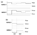
図6(a),(b)は、画像形成装置の消費電力と商用電源の電圧低下の関係を示すグラフであり、図7は、画像形成装置の消費電力と商用電源の入力部の電圧低下と定着温度の関係を示すグラフである。 6A and 6B are graphs showing the relationship between the power consumption of the image forming apparatus and the voltage drop of the commercial power supply, and FIG. 7 is the voltage drop of the power consumption of the image forming apparatus and the input portion of the commercial power supply. 5 is a graph showing the relationship between the fixing temperature and the fixing temperature.
図6(a)のように、画像形成装置の消費電力Pが下限電力Pmin以下の微少のときには、通常電圧Vtyp=100Vに対して電源電圧Vの電圧低下量が微少である。その後、消費電力Pが上限電力Pmaxまで増加しても、電源電圧Vが動作保証できる下限保証電圧Vlimit=85Vまで低下しなければ装置は正常に動作可能である。 As shown in FIG. 6A, when the power consumption P of the image forming apparatus is very small below the lower limit power Pmin, the amount of voltage drop of the power supply voltage V is small with respect to the normal voltage Vtyp = 100V. Thereafter, even if the power consumption P increases to the upper limit power Pmax, the apparatus can operate normally if the power supply voltage V does not decrease to the lower limit guaranteed voltage Vlimit = 85V at which the operation can be guaranteed.
しかし、図6(b)のように、消費電力Pが微少であるときに既に電源電圧Vが外的要因で85V近傍まで低下している場合(601)には、その後の定着電力の印加などで消費電力が増加すると、電源電圧Vが下限保証電圧85Vを下回る恐れがある。
However, as shown in FIG. 6B, when the power supply voltage V has already decreased to about 85 V due to an external factor when the power consumption P is very small (601), the subsequent application of fixing power, etc. When the power consumption increases, the power supply voltage V may fall below the lower limit guaranteed
このため、上記状態で、特許文献2のように、定着性確保できる下限定着電力から画像形成装置を動作させようとしても、次のような問題が生ずる。即ち、該画像形成装置の電力消費による電圧低下が重畳され、画像形成装置自身またはコンセントを共用している他の装置の異常動作につながる恐れがある。 For this reason, even if the image forming apparatus is operated from the lower limit fixing power capable of ensuring the fixing property in the above-described state, the following problem occurs. That is, the voltage drop due to the power consumption of the image forming apparatus is superimposed, which may lead to abnormal operation of the image forming apparatus itself or another apparatus sharing the outlet.
さらに、画像形成中に電圧低下を検知した場合でも、外部要因による電圧低下時は下限定着電力まで定着電力を下げても電圧低下を解消できない。従って、プリント動作の継続、即ち定着電力の印加を継続すると、画像形成装置自身またはコンセントを共用している他の装置の異常動作につながる恐れがある。 Further, even when a voltage drop is detected during image formation, the voltage drop cannot be resolved even if the fixing power is lowered to the lower limit fixing power when the voltage drops due to an external factor. Therefore, if the printing operation is continued, that is, the application of the fixing power is continued, there is a possibility that the image forming apparatus itself or another apparatus sharing the outlet may be abnormally operated.
一方、電圧低下が定着電力を低減することで解消されるような画像形成装置本体による要因である場合、次のようなことが言える。即ち、図7の603のように消費電力Pが上限電力Pmaxまで増加すると電圧低下が下限保証電圧Vlimit=85Vまで達するので異常動作に至る懸念がある。しかし、604〜605のように消費電力を低減させれば、電圧低下量が下限保証電圧Vlimit=85Vに対して余裕が増加する。そのため、例えば最大印加可能電力をPmax2に低下させれば動作継続可能である。
On the other hand, when the voltage drop is a factor of the image forming apparatus main body that can be eliminated by reducing the fixing power, the following can be said. That is, when the power consumption P increases to the upper limit power Pmax as indicated by
また、このときでも定着温度Tfixは、最大電力が低減するために目標温度(=Ttarget)よりも低下するが、定着性が確保できる最低温度Tlimit以上であれば用紙搬送速度を低下させる必要はない。 Even at this time, the fixing temperature Tfix is lower than the target temperature (= Ttarget) because the maximum power is reduced, but it is not necessary to reduce the sheet conveyance speed as long as it is equal to or higher than the minimum temperature Tlimit that can secure the fixing property. .
然るに、特許文献1のように、上記の点を考慮せずにプリント速度を電圧低下率に比例して低下させることで電力低減を図る方法は、即座に画像形成処理枚数の低下につながるため、利用者に不利益をもたらす。
However, as in
本発明は上記従来の問題点に鑑み、商用電源の電圧低下による動作異常を防ぎ、かつ電圧低下があっても画像形成動作を効率的に継続することができる画像形成装置及びその制御方法を提供することを目的とする。 SUMMARY OF THE INVENTION In view of the above-described conventional problems, the present invention provides an image forming apparatus capable of preventing an abnormal operation due to a voltage drop of a commercial power source and efficiently continuing an image forming operation even when the voltage drops, and a control method therefor. The purpose is to do.
本発明は上記目的を達成するため、画像情報に基づいて記録媒体にトナー画像を形成する手段と、前記記録媒体上のトナー画像を加熱定着させる定着手段とを備えた画像形成装置において、商用電源の入力部における電圧低下を測定する電圧検知手段と、前記定着手段の駆動電力である定着電力を設定する設定手段と、前記設定手段によって設定された定着設定電力が閾値以下である場合に前記電圧検知手段を用いて測定された電圧低下量が所定値以上であることを検知したとき、当該画像形成装置の動作を停止させる制御を行う第1の制御手段と、前記定着設定電力が前記閾値以上である場合に前記電圧検知手段を用いて測定された電圧低下量が所定値以上であることを検知したとき、前記定着設定電力を低減させて当該画像形成装置の動作を継続する制御を行う第2の制御手段とを備えたことを特徴とする。 In order to achieve the above object, the present invention provides an image forming apparatus comprising a unit for forming a toner image on a recording medium based on image information and a fixing unit for heating and fixing the toner image on the recording medium. Voltage detecting means for measuring a voltage drop at the input section, setting means for setting fixing power which is driving power of the fixing means, and the voltage when the fixing setting power set by the setting means is less than or equal to a threshold value A first control unit that performs control to stop the operation of the image forming apparatus when it is detected that the amount of voltage decrease measured using the detection unit is equal to or greater than a predetermined value; When it is detected that the amount of voltage drop measured using the voltage detecting means is equal to or greater than a predetermined value, the fixing power setting is reduced to operate the image forming apparatus. Characterized by comprising a second control means for controlling to continue.
また、本発明は、画像情報に基づいて記録媒体にトナー画像を形成する手段と、前記記録媒体上のトナー画像を加熱定着させる定着手段と、商用電源の入力部における電圧低下を測定する電圧検知手段とを備えた画像形成装置の制御方法であって、前記定着手段の駆動電力である定着電力を設定する設定工程と、前記設定工程によって設定された定着設定電力が閾値以下である場合に前記電圧検知手段を用いて測定された電圧低下量が所定値以上であることを検知したとき、当該画像形成装置の動作を停止させる制御を行う第1の制御工程と、前記定着設定電力が前記閾値以上である場合に前記電圧検知手段を用いて測定された電圧低下量が所定値以上であることを検知したとき、前記定着設定電力を低減させて当該画像形成装置の動作を継続する制御を行う第2の制御工程とを有することを特徴とする。 The present invention also provides a means for forming a toner image on a recording medium based on image information, a fixing means for heating and fixing the toner image on the recording medium, and a voltage detection for measuring a voltage drop at an input section of a commercial power source. A setting step of setting a fixing power that is a driving power of the fixing unit, and when the fixing setting power set by the setting step is equal to or less than a threshold value. A first control step for performing control to stop the operation of the image forming apparatus when it is detected that the amount of voltage decrease measured using the voltage detection unit is equal to or greater than a predetermined value; When it is above, when it is detected that the voltage drop amount measured using the voltage detecting means is a predetermined value or more, the fixing set power is reduced and the operation of the image forming apparatus is continued. And having a second control step of performing control to.
本発明によれば、商用電源の電圧低下による動作異常を防ぐことができ、かつ電圧低下があっても画像形成動作を効率的に継続することが可能である。 According to the present invention, it is possible to prevent an abnormal operation due to a voltage drop of a commercial power supply, and to continue an image forming operation efficiently even if the voltage drops.
以下、本発明の実施の形態について、図面を参照しながら説明する。 Hereinafter, embodiments of the present invention will be described with reference to the drawings.
[第1の実施の形態]
<画像処理装置の構成>
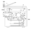
図1は、本発明の実施の形態における画像処理装置の全体的な概略構成を示す断面図である。本実施の形態では、画像処理装置として、原稿給送装置1、リーダ部100、プリンタ部200、及び操作部300から構成されるディジタル複写装置を例に挙げる。
[First Embodiment]
<Configuration of image processing apparatus>
FIG. 1 is a cross-sectional view showing an overall schematic configuration of an image processing apparatus according to an embodiment of the present invention. In the present embodiment, a digital copying apparatus including the
図1に示すように、原稿給送装置1は、載置された原稿を1枚ずつ或いは2枚連続に原稿台ガラス面2上の所定位置に給送するADF(オート・ドキュメント・フィーダ)等で構成されている。原稿給送装置1により原稿が原稿台ガラス面2に載置されると、リーダ部100のスキャナ4が所定方向に往復走査されて原稿反射光を走査ミラーやレンズを通過してイメージセンサ部101に結像する。イメージセンサ部101で光電変換された画像データ(画像情報)はコントローラ部CONTへ送出される。
As shown in FIG. 1, the
プリンタ部200は、コントローラ部CONT、露光制御部10、感光体11、現像器12,13、記録媒体積載部14,15、転写分離帯電器16、及び定着器102等で構成されている。
The
コントローラ部CONTは、画像データに基づいて変調された光ビームを生成する。露光制御部10は、レーザースキャナで構成され、コントローラ部CONTから出力される画像データに基づいて変調された光ビームを感光体11に照射する。
The controller unit CONT generates a light beam modulated based on the image data. The
現像器12,13は、感光体11に形成された静電潜像を所定色の現像剤(トナー)で可視化してトナー画像を形成する。記録媒体積載部14,15は、定形サイズの記録媒体Pを積載して収納している。記録媒体積載部14,15から給紙された記録媒体Pは、給送ローラの駆動によりレジストローラ25の配置位置まで給送されて一時停止する。その後、感光体11に形成される画像とのタイミングをとられた状態で再給紙される。
The developing
転写分離帯電器16は、感光体11に現像されたトナー像を記録媒体Pに転写する。その後、記録媒体Pは、感光体11より分離して搬送ベルトを介して定着器102に搬送される。定着器102は、対向する加熱ローラと加圧ローラ17を有し、これらローラで形成されるニップを記録媒体Pが通過することで、未定着のトナー像を記録媒体Pの表面に加熱定着する。
The
排紙ローラ18は、上記のようにして画像形成を終了した記録媒体Pをトレー20に積載排紙する。操作部300は動作指令を入力するSW及び情報表示手段を備えたである。
The
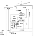
図2は、第1の実施の形態における画像形成装置の電力系統の概略構成を示すブロック図である。 FIG. 2 is a block diagram illustrating a schematic configuration of the power system of the image forming apparatus according to the first embodiment.
本実施の形態の画像形成装置は、主な電気的な構成要素として、本体制御部202、電圧検知部203、定着制御部204、DC電源205、DC負荷206、及びAC負荷(定着器102以外)207などを有している。
The image forming apparatus according to the present embodiment includes main
本体制御部202は、例えば図1中のコントローラCONT内に設けられ、プリンタ部200の動作を制御する機能を有する。電圧検知部203は、画像形成装置本体の電源を取り込む入力部に入力される商用電源201の電圧Vacを測定し、本体制御部202へ随時通知する。定着制御部204は、本体制御部202からの定着電力制御に応じて、定着器102の駆動電力である定着電力を定着設定電力として設定して制御する。
The main
DC電源205は、本体制御部202から動作制御されるモータなどを含むDC負荷206や原稿読取装置1にDC電力を供給する電源回路である。また、ACラインには上記定着器102やDC電源205のほかにも補助ヒータなどを含むAC負荷207も接続されており、本体制御部202の制御で適切に駆動される。
The
また、本体制御部202は、定着器102の温度Tfixをサーミスタ209などの温度検知素子で常時監視し、定着設定電力Pfixが常に最適化されるように動作する。つまり、プリント動作中は
Tfix≒目標温度(定着適温度)
となるように定着設定電力Pfixを上限値Pmaxから0の範囲で適切に制御し、過大設定や過少設定にならないようにする。
Further, the main
The fixing setting power Pfix is appropriately controlled in the range from the upper limit value Pmax to 0 so that the setting value does not become an excessive setting or an under setting.
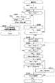
<第1の実施の形態における動作>
次に、上記画像形成装置の電圧監視及び電力制御動作について、図3を参照して説明する。図3は、第1の実施の形態に係る動作を示すフローチャートである。このフローチャートは本体制御部(以下、制御部と称す)202により実行される。
<Operation in First Embodiment>
Next, voltage monitoring and power control operations of the image forming apparatus will be described with reference to FIG. FIG. 3 is a flowchart showing an operation according to the first embodiment. This flowchart is executed by a main body control unit (hereinafter referred to as a control unit) 202.
まず画像形成装置の電源をオンすると、制御部202は定着設定電力Pfix=0に設定する(ステップS301)。制御部202は、電圧検知部203にて入力電圧Vacを計測し、入力電圧Vacが動作保証下限電圧Vmin以下になっているか否かを判断する(ステップS302)。入力電圧Vacが動作保証下限電圧Vmin以下の場合、制御部202は定着電力がどの程度印加されているかを判断する(ステップS303)。即ち、制御部202は定着設定電力Pfixと画像形成装置の下限電力Pminとの大小比較を行う。
First, when the power of the image forming apparatus is turned on, the
ここで、動作保証下限電圧Vminは、例えば日本における公称電圧100Vに対して当該画像形成装置が正常に動作保証できる電圧80〜85V程度に設定するのが適切であり、先に説明した動作保証下限電圧Vlimitに対して、
Vlimit<Vmin
とする。
Here, the operation guarantee lower limit voltage Vmin is appropriately set to a voltage of about 80 to 85 V at which the image forming apparatus can normally guarantee the operation with respect to the
Vlimit <Vmin
And
最初は定着設定電力Pfix=0であり、定着設定電力Pfixが下限電力Pminより明らかに小さいので、ステップS304の処理が実行される。即ち、制御部202は、プリント動作を停止し、商用電源電圧が異常に低下して正常動作できないことを使用者に操作部300の表示部に警告表示したり音などで通知する。
Initially, the fixing setting power Pfix = 0, and the fixing setting power Pfix is clearly smaller than the lower limit power Pmin, so the process of step S304 is executed. That is, the
一方、ステップS302で、入力電圧Vacが動作保証下限電圧Vminに達していなければ、本体制御部202は、定着電力を立ち上げて定着設定電力PfixをP1に設定する(ステップS305)。これにより、定着器102が加熱される。そして、制御部202は、サーミスタ209で検知される定着温度Tfixがプリント可能温度T1になるまで加熱する(ステップS307)。
On the other hand, if the input voltage Vac does not reach the operation guarantee lower limit voltage Vmin in step S302, the main
但し、この定着電力立ち上げ中も入力電圧Vacの測定は継続している。そして、入力電圧Vacが動作保証下限電圧Vmin以下に低下した場合、制御部202は、定着設定電力Pfixが下限電力Pminより大きければ一定電力ΔPずつ低減して入力電圧Vacの低下を軽減しようとする(ステップS306)。
However, the measurement of the input voltage Vac is continued even during the rise of the fixing power. When the input voltage Vac falls below the operation guarantee lower limit voltage Vmin, the
なお、初期の設定電力P1と下限電力Pminは
0≦Pmin<P1
と設定されるのが通常である。
The initial set power P1 and the lower limit power Pmin are 0 ≦ Pmin <P1.
It is usually set as
次に定着温度Tfixがプリント可能温度T1に達すると、プリント可能となるので制御部202は、定着設定電力Pfixを目標温度T1と測定温度Tfixの差に比例した電力に設定し、
Tfix≒T1
を維持するよう制御する。また制御部202は、プリント速度Vpを初期の最大速度Vpmaxに設定する(ステップS308)。
Next, when the fixing temperature Tfix reaches the printable temperature T1, printing is possible, so the
Tfix≈T1
Control to maintain. The
制御部202はプリント動作中も、上記の定着電力立ち上げ中と同様に入力電圧Vacの測定を継続し、Vac<Vminになったか否かを判断する(ステップS309)。Vac<Vminになると、制御部202は定着設定電力Pfixが下限電力Pminより小ければ(ステップS310)、前記ステップS304の処理を実行する。即ち、制御部202はプリント動作を停止するとともに、外部要因による電圧低下の可能性あることを操作部300において報知する。
The
定着設定電力Pfixが下限電力Pminよりも大きい場合、制御部202は、一定電力ΔPだけ定着電力を減ずる(ステップS311)。但し、定着温度Tfixには、記録媒体上にトナー画像を定着するのに最低限必要な下限温度T2が設定されているので、制御部202は定着電力を減じたことで定着器温度TfixがT2を下回ったか否かを監視する(ステップS312)。
When the fixing setting power Pfix is larger than the lower limit power Pmin, the
Tfix<T2となると、制御部202は、例えばプリント速度Vpを初期の速度VpMAxの1/2に低下させる(ステップS313)。これにより、定着器102は記録媒体に単位時間当たり奪われる熱量が減じられ、Tfix≧T2に回復するよう制御される。
When Tfix <T2, the
温度がT2以上になれば、制御部202は、プリント速度をVpmaxに復帰させる(ステップS314)。これにより、定着性の確保と生産性の両立が図られる。
If the temperature becomes equal to or higher than T2, the
この制御は、プリント動作が所望の枚数終了するまで継続される(ステップS315)。 This control is continued until the desired number of print operations is completed (step S315).
<第1の実施の形態に係る利点>
第1の実施の形態によれば、次のような利点を有する。
(1)定着設定電力Pfixが閾値以下(例えば下限電力Pmin以下)に設定されている場合に、測定された電圧低下量が所定値以上であることを検知したときは(例えば入力電圧Vac<動作保証下限電圧Vmin)、次のような制御(第1の制御)を行う。即ち、外部要因による電圧低下であると判断し、当該画像形成装置のプリント動作を停止させると共に、商用電源電圧が異常に低下して正常動作できない旨を、使用者に対して通知する。これにより、画像形成装置自身或いはコンセントを共用する他の機器の動作停止など不要な異常動作に至る可能性を減少させることができる。
<Advantages of First Embodiment>
The first embodiment has the following advantages.
(1) When the fixing set power Pfix is set to a threshold value or less (for example, the lower limit power Pmin or less), when it is detected that the measured voltage drop amount is a predetermined value or more (for example, input voltage Vac <operation Guaranteed lower limit voltage Vmin), the following control (first control) is performed. That is, it is determined that the voltage is reduced due to an external factor, and the printing operation of the image forming apparatus is stopped, and the user is notified that the commercial power supply voltage is abnormally lowered and cannot be normally operated. As a result, it is possible to reduce the possibility of an unnecessary abnormal operation such as an operation stop of the image forming apparatus itself or another device sharing the outlet.
(2)定着設定電力Pfixが閾値以上(例えば下限電力Pmin以上)に設定されている場合に、電圧検知部203を用いて測定された電圧低下量が所定値以上であることを検知したときは、次のような制御(第2の制御)を行う。即ち、当該画像形成装置自身の電力消費に起因する電圧低下であると判断し、定着設定電力を低減させて電圧低下を軽減するように制御する。これにより、電圧低下検知時であっても、極力、プリント処理の生産性を低下させず画像形成装置の動作を継続することができる。
(2) When it is detected that the voltage drop amount measured using the
なお、第1の実施の形態において、定着温度が所定値以下の時の復帰手段として、記録媒体搬送速度を1/2に低下させる、つまり、単位時間当たりの画像形成処理枚数を低下することで必要熱量を低下させる例を示したが、この場合の速度低下率は一義に決定する必要はなく、定着ローラ17の熱容量などで経験的に求めてよい。また、複数段階の速度切り換えでも構わないのは容易に推測可能である。また、記録媒体を搬送する間隔を広げることでも同様に単位必要熱量を低下させて定着温度を回復させる効果があるのは明らかである。
In the first embodiment, as a return means when the fixing temperature is equal to or lower than a predetermined value, the recording medium conveyance speed is reduced to ½, that is, the number of image forming processes per unit time is reduced. Although an example of reducing the required heat amount has been shown, the speed reduction rate in this case does not need to be uniquely determined, and may be obtained empirically from the heat capacity of the fixing
[第2の実施の形態]
次に、本発明の第2の実施の形態について説明する。
[Second Embodiment]
Next, a second embodiment of the present invention will be described.
<第2の実施の形態に係る構成>
図4は、本発明の第2の実施の形態における画像形成装置の電力系統の概略構成を示すブロック図であり、図2と共通の要素には同一の符号を付し、その説明を省略する。
<Configuration according to the second embodiment>
FIG. 4 is a block diagram showing a schematic configuration of the power system of the image forming apparatus according to the second embodiment of the present invention. Elements common to those in FIG. .
第2の実施の形態の構成が第1の実施の形態の構成と異なる点は、画像形成装置本体の総消費電流を測定する電流センサ401(電流検知手段)を設け、本体制御部202では、電流センサ401の測定値を用いた制御を行うようにした点である。即ち、本体制御部202では、定着駆動開始前に所定負荷を駆動したときの電流増加量と電圧低下量から定着器102に印加する定着設定電力の最大値を算出するようにする。以下、本実施の形態の動作を具体的に説明する。
The configuration of the second embodiment is different from the configuration of the first embodiment in that a current sensor 401 (current detection unit) that measures the total current consumption of the image forming apparatus main body is provided. This is a point where control using the measured value of the
<第2の実施の形態に係る動作>
次に、本実施の形態の動作について図5を参照して説明する。図5は、第2の実施の形態に係る動作を示すフローチャートである。このフローチャートは本体制御部(以下、制御部と称す)202により実行される。
<Operation According to Second Embodiment>
Next, the operation of the present embodiment will be described with reference to FIG. FIG. 5 is a flowchart showing an operation according to the second embodiment. This flowchart is executed by a main body control unit (hereinafter referred to as a control unit) 202.
画像形成装置の電源のオン時において、制御部202は、第1の実施の形態と同様に、定着設定電力Pfix=0としておく(ステップS501)。また、制御部202は電圧検知部203及び電流センサ401により入力電圧Vac及び消費電流Iallを測定し、それぞれVac1、Iall1として制御部202内の不図示のメモリに記憶しておく(ステップS502)。その後、制御部202は、例えばAC負荷207を動作させ(ステップS503)、同様に入力電圧Vac2、Iall2を記憶する(ステップS504)。
When the power of the image forming apparatus is turned on, the
そして、制御部202は、次式に基づいて電圧低下量ΔV及び電流増加量ΔIを計算する(ステップS505)。
Then, the
電圧低下量ΔV=Vac1−Vac2
電流増加量ΔI=Iall2−Iall1
また、制御部202は、次式に基づいて最大低下電圧ΔVmax及び印加可能最大電流Imaxを決定する(ステップS506)。
Voltage drop amount ΔV = Vac1−Vac2
Current increase amount ΔI = Iall2-Iall1
Further, the
最大低下電圧ΔVmax=Vac1−Vmin
印加可能最大電流Imax=ΔVmax×ΔI/ΔV
そして制御部202は、定着器102に印加できる最大電力
Pfixmax≒Vmin×Imax
で定着器102を立ち上げる(ステップS507)。これにより、電圧低下を動作保証下限電圧Vmin以内に収めることが可能である。
Maximum drop voltage ΔVmax = Vac1−Vmin
Applicable maximum current Imax = ΔVmax × ΔI / ΔV
The
Pfixmax≈Vmin × Imax
Then, the fixing
その後の制御は第1の実施の形態と同様である。 Subsequent control is the same as in the first embodiment.
<第2の実施の形態に係る利点>
第2の実施の形態によれば、上記第1の実施の形態と同等の利点を奏すると共に、商用電源の電圧低下を、画像形成装置の動作保証下限電圧Vmin以内に収めることが可能である。
<Advantages of Second Embodiment>
According to the second embodiment, the same advantages as the first embodiment can be obtained, and the voltage drop of the commercial power supply can be kept within the operation guarantee lower limit voltage Vmin of the image forming apparatus.
なお、第2の実施の形態において電圧低下量を測定するときに動作させる負荷をAC負荷207としたが 入力電流増加と入力電圧低下が測定可能であれば、特定のDC負荷206を動作させても可能である。または、定着設定電力Pfixを微少に設定して、定着器102を動作させることでも測定可能なのは明らかである。
In the second embodiment, the
本発明の目的は、以下の処理を実行することによっても達成される。即ち、上述した実施形態の機能を実現するソフトウェアのプログラムコードを記録した記憶媒体を、システム或いは装置に供給し、そのシステム或いは装置のコンピュータ(またはCPUやMPU等)が記憶媒体に格納されたプログラムコードを読み出す処理である。 The object of the present invention can also be achieved by executing the following processing. That is, a storage medium in which a program code of software that realizes the functions of the above-described embodiments is supplied to a system or apparatus, and a computer (or CPU or MPU) of the system or apparatus is stored in the storage medium. This is the process of reading the code.
この場合、記憶媒体から読み出されたプログラムコード自体が前述した実施の形態の機能を実現することになり、そのプログラムコード及び該プログラムコードを記憶した記憶媒体は本発明を構成することになる。 In this case, the program code itself read from the storage medium realizes the functions of the above-described embodiments, and the program code and the storage medium storing the program code constitute the present invention.
また、プログラムコードを供給するための記憶媒体としては、次のものを用いることができる。例えば、フロッピー(登録商標)ディスク、ハードディスク、光磁気ディスク、CD−ROM、CD−R、CD−RW、DVD−ROM、DVD−RAM、DVD−RW、DVD+RW、磁気テープ、不揮発性のメモリカード、ROM等である。または、プログラムコードをネットワークを介してダウンロードしてもよい。 Moreover, the following can be used as a storage medium for supplying the program code. For example, floppy (registered trademark) disk, hard disk, magneto-optical disk, CD-ROM, CD-R, CD-RW, DVD-ROM, DVD-RAM, DVD-RW, DVD + RW, magnetic tape, nonvolatile memory card, ROM or the like. Alternatively, the program code may be downloaded via a network.
また、コンピュータが読み出したプログラムコードを実行することにより、上記実施の形態の機能が実現される場合も本発明に含まれる。加えて、そのプログラムコードの指示に基づき、コンピュータ上で稼動しているOS(オペレーティングシステム)等が実際の処理の一部または全部を行い、その処理によって前述した実施形態の機能が実現される場合も含まれる。 Further, the present invention includes a case where the function of the above embodiment is realized by executing the program code read by the computer. In addition, an OS (operating system) running on the computer performs part or all of the actual processing based on an instruction of the program code, and the functions of the above-described embodiments are realized by the processing. Is also included.
更に、前述した実施形態の機能が以下の処理によって実現される場合も本発明に含まれる。即ち、記憶媒体から読み出されたプログラムコードが、コンピュータに挿入された機能拡張ボードやコンピュータに接続された機能拡張ユニットに備わるメモリに書き込まれる。その後、そのプログラムコードの指示に基づき、その機能拡張ボードや機能拡張ユニットに備わるCPU等が実際の処理の一部または全部を行う場合である。 Furthermore, a case where the functions of the above-described embodiment are realized by the following processing is also included in the present invention. That is, the program code read from the storage medium is written in a memory provided in a function expansion board inserted into the computer or a function expansion unit connected to the computer. Thereafter, based on the instruction of the program code, the CPU or the like provided in the function expansion board or function expansion unit performs part or all of the actual processing.
102 定着器
202 本体制御部
203 電圧検知部
204 定着制御部
300 操作部
209 サーミスタ
401 電流検知センサ
102
Claims (7)
商用電源の入力部における電圧低下を測定する電圧検知手段と、
前記定着手段の駆動電力である定着電力を設定する設定手段と、
前記設定手段によって設定された定着設定電力が閾値以下である場合に前記電圧検知手段を用いて測定された電圧低下量が所定値以上であることを検知したとき、当該画像形成装置の動作を停止させる制御を行う第1の制御手段と、
前記定着設定電力が前記閾値以上である場合に前記電圧検知手段を用いて測定された電圧低下量が所定値以上であることを検知したとき、前記定着設定電力を低減させて当該画像形成装置の動作を継続する制御を行う第2の制御手段とを備えたことを特徴とする画像形成装置。 In an image forming apparatus comprising: means for forming a toner image on a recording medium based on image information; and fixing means for heating and fixing the toner image on the recording medium.
Voltage detection means for measuring voltage drop at the input of the commercial power supply;
Setting means for setting fixing power which is driving power of the fixing means;
When the fixing power set by the setting unit is less than or equal to a threshold value, the operation of the image forming apparatus is stopped when it is detected that the amount of voltage drop measured using the voltage detection unit is greater than or equal to a predetermined value. First control means for performing control,
When it is detected that the amount of voltage drop measured using the voltage detection unit is greater than or equal to a predetermined value when the fixing setting power is greater than or equal to the threshold value, the fixing setting power is reduced to reduce the fixing setting power. An image forming apparatus comprising: a second control unit that performs control to continue the operation.
前記第1の制御手段は、前記報知手段によって、商用電源の入力が異常である旨を報知することを特徴とする請求項1に記載の画像形成装置。 Having a notification means for reporting information to the outside;
The image forming apparatus according to claim 1, wherein the first control unit notifies that the input of a commercial power source is abnormal by the notification unit.
前記温度検知手段によって検知された温度が所定値以下である場合に単位時間当たりの画像形成処理枚数を低下させる制御を行う手段とを備えたことを特徴とする請求項1または2に記載の画像形成装置。 Temperature detecting means for detecting the temperature of the fixing means;
3. The image according to claim 1, further comprising: a control unit configured to control to reduce the number of image forming processes per unit time when the temperature detected by the temperature detection unit is equal to or lower than a predetermined value. Forming equipment.
前記定着手段の駆動開始前に、所定負荷を駆動したときの電流増加量と電圧低下量に基づいて前記定着設定電力の最大値を決定する手段とを有することを特徴とする請求項1乃至5のいずれか一項に記載の画像形成装置。 Current detection means for measuring the total current consumption of the image forming apparatus;
6. The apparatus according to claim 1, further comprising: a unit that determines a maximum value of the fixing setting power based on a current increase amount and a voltage decrease amount when a predetermined load is driven before driving of the fixing unit. The image forming apparatus according to claim 1.
前記定着手段の駆動電力である定着電力を設定する設定工程と、
前記設定工程によって設定された定着設定電力が閾値以下である場合に前記電圧検知手段を用いて測定された電圧低下量が所定値以上であることを検知したとき、当該画像形成装置の動作を停止させる制御を行う第1の制御工程と、
前記定着設定電力が前記閾値以上である場合に前記電圧検知手段を用いて測定された電圧低下量が所定値以上であることを検知したとき、前記定着設定電力を低減させて当該画像形成装置の動作を継続する制御を行う第2の制御工程とを有することを特徴とする画像形成装置の制御方法。 An image comprising means for forming a toner image on a recording medium based on image information, fixing means for heating and fixing the toner image on the recording medium, and voltage detection means for measuring a voltage drop at an input section of a commercial power source A method for controlling a forming apparatus, comprising:
A setting step of setting a fixing power which is a driving power of the fixing unit;
The operation of the image forming apparatus is stopped when it is detected that the amount of voltage decrease measured using the voltage detection unit is equal to or greater than a predetermined value when the fixing setting power set in the setting step is less than or equal to a threshold value. A first control step for performing control,
When it is detected that the amount of voltage drop measured using the voltage detection unit is greater than or equal to a predetermined value when the fixing setting power is greater than or equal to the threshold value, the fixing setting power is reduced to reduce the fixing setting power. And a second control step for performing control to continue the operation.
Priority Applications (2)
| Application Number | Priority Date | Filing Date | Title |
|---|---|---|---|
| JP2008292164A JP2010117652A (en) | 2008-11-14 | 2008-11-14 | Image forming device and control method of the same |
| US12/616,602 US8285158B2 (en) | 2008-11-14 | 2009-11-11 | Image forming apparatus and control method therefor |
Applications Claiming Priority (1)
| Application Number | Priority Date | Filing Date | Title |
|---|---|---|---|
| JP2008292164A JP2010117652A (en) | 2008-11-14 | 2008-11-14 | Image forming device and control method of the same |
Publications (2)
| Publication Number | Publication Date |
|---|---|
| JP2010117652A true JP2010117652A (en) | 2010-05-27 |
| JP2010117652A5 JP2010117652A5 (en) | 2012-01-05 |
Family
ID=42172149
Family Applications (1)
| Application Number | Title | Priority Date | Filing Date |
|---|---|---|---|
| JP2008292164A Pending JP2010117652A (en) | 2008-11-14 | 2008-11-14 | Image forming device and control method of the same |
Country Status (2)
| Country | Link |
|---|---|
| US (1) | US8285158B2 (en) |
| JP (1) | JP2010117652A (en) |
Cited By (5)
| Publication number | Priority date | Publication date | Assignee | Title |
|---|---|---|---|---|
| JP2015049345A (en) * | 2013-08-30 | 2015-03-16 | 京セラドキュメントソリューションズ株式会社 | Image forming apparatus |
| JP2016218176A (en) * | 2015-05-18 | 2016-12-22 | 株式会社リコー | Image forming apparatus, image forming method, and program |
| JP2017207705A (en) * | 2016-05-20 | 2017-11-24 | 株式会社リコー | Method for controlling image forming apparatus |
| JP2018116186A (en) * | 2017-01-19 | 2018-07-26 | キヤノン株式会社 | Image forming device |
| US11156949B2 (en) | 2017-01-19 | 2021-10-26 | Canon Kabushiki Kaisha | Image forming apparatus |
Families Citing this family (3)
| Publication number | Priority date | Publication date | Assignee | Title |
|---|---|---|---|---|
| JP5780812B2 (en) * | 2010-05-12 | 2015-09-16 | キヤノン株式会社 | Voltage detection device and image heating device |
| JP5494989B2 (en) * | 2012-01-26 | 2014-05-21 | コニカミノルタ株式会社 | Printing system and image forming apparatus |
| JP6711132B2 (en) * | 2016-05-20 | 2020-06-17 | 株式会社リコー | Image forming apparatus control method |
Citations (3)
| Publication number | Priority date | Publication date | Assignee | Title |
|---|---|---|---|---|
| JPS60121480A (en) * | 1983-12-05 | 1985-06-28 | Sharp Corp | Heat fixing device |
| JP2003103876A (en) * | 2001-09-27 | 2003-04-09 | Canon Inc | Imaging apparatus and its controlling method |
| JP2007102008A (en) * | 2005-10-06 | 2007-04-19 | Sharp Corp | Image forming apparatus |
Family Cites Families (5)
| Publication number | Priority date | Publication date | Assignee | Title |
|---|---|---|---|---|
| JP2004226888A (en) | 2003-01-27 | 2004-08-12 | Konica Minolta Holdings Inc | Image forming apparatus |
| JP4449547B2 (en) * | 2003-09-17 | 2010-04-14 | コニカミノルタビジネステクノロジーズ株式会社 | Image forming apparatus |
| US7433620B2 (en) * | 2004-07-13 | 2008-10-07 | Canon Kabushiki Kaisha | Image forming apparatus with controlled electric power supply to heating member |
| JP4943100B2 (en) * | 2005-09-16 | 2012-05-30 | 株式会社リコー | Image forming apparatus |
| JP4931045B2 (en) * | 2006-06-06 | 2012-05-16 | 株式会社リコー | Power supply device and image forming apparatus |
-
2008
- 2008-11-14 JP JP2008292164A patent/JP2010117652A/en active Pending
-
2009
- 2009-11-11 US US12/616,602 patent/US8285158B2/en active Active
Patent Citations (3)
| Publication number | Priority date | Publication date | Assignee | Title |
|---|---|---|---|---|
| JPS60121480A (en) * | 1983-12-05 | 1985-06-28 | Sharp Corp | Heat fixing device |
| JP2003103876A (en) * | 2001-09-27 | 2003-04-09 | Canon Inc | Imaging apparatus and its controlling method |
| JP2007102008A (en) * | 2005-10-06 | 2007-04-19 | Sharp Corp | Image forming apparatus |
Cited By (7)
| Publication number | Priority date | Publication date | Assignee | Title |
|---|---|---|---|---|
| JP2015049345A (en) * | 2013-08-30 | 2015-03-16 | 京セラドキュメントソリューションズ株式会社 | Image forming apparatus |
| JP2016218176A (en) * | 2015-05-18 | 2016-12-22 | 株式会社リコー | Image forming apparatus, image forming method, and program |
| JP2017207705A (en) * | 2016-05-20 | 2017-11-24 | 株式会社リコー | Method for controlling image forming apparatus |
| JP2018116186A (en) * | 2017-01-19 | 2018-07-26 | キヤノン株式会社 | Image forming device |
| US11156949B2 (en) | 2017-01-19 | 2021-10-26 | Canon Kabushiki Kaisha | Image forming apparatus |
| JP6991715B2 (en) | 2017-01-19 | 2022-01-12 | キヤノン株式会社 | Image forming device |
| US11720040B2 (en) | 2017-01-19 | 2023-08-08 | Canon Kabushiki Kaisha | Image forming apparatus |
Also Published As
| Publication number | Publication date |
|---|---|
| US20100124425A1 (en) | 2010-05-20 |
| US8285158B2 (en) | 2012-10-09 |
Similar Documents
| Publication | Publication Date | Title |
|---|---|---|
| JP2010117652A (en) | Image forming device and control method of the same | |
| US9235182B2 (en) | Fixing device capable of detecting wrap jam of recording sheet and image forming apparatus | |
| JP2007327989A (en) | Power supply and image forming apparatus | |
| JP2010049087A (en) | Image forming apparatus and electric power control method | |
| JP2007102008A (en) | Image forming apparatus | |
| US9523948B2 (en) | Image forming apparatus, image formation control method, and computer program product | |
| JP2005148581A (en) | Image forming apparatus and auxiliary power supply feeding method for image forming apparatus | |
| JP4944546B2 (en) | Electrical apparatus and image forming apparatus | |
| US9046836B2 (en) | Image forming apparatus for restricting excessive temperature rise of fixing member | |
| JP5298845B2 (en) | Image forming apparatus | |
| JP2015194600A (en) | Image forming device | |
| JP2008216549A (en) | Image forming device | |
| JP5873827B2 (en) | Image forming apparatus and method of controlling image forming apparatus | |
| US8095029B2 (en) | Controlling fixing device temperature of an image forming apparatus based on target temperature | |
| JP2007298834A (en) | Image forming apparatus | |
| JP2005181778A (en) | Image forming apparatus | |
| JP2020024313A (en) | Image formation apparatus and method of controlling the same | |
| JP2009145748A (en) | Image forming apparatus | |
| JP2007148194A (en) | Image forming apparatus | |
| JP5752895B2 (en) | Image forming apparatus | |
| JP2005241660A (en) | Image forming apparatus | |
| JP2005047152A (en) | Image forming device | |
| JP2015169662A (en) | Fixing control device, image forming apparatus, fixing control method, and fixing control program | |
| JP2015040929A (en) | Thermal power generation apparatus, image forming apparatus, thermal power generation control method, and thermal power generation control program | |
| JP2013041175A (en) | Image forming apparatus, fixation control method, program, and record medium |
Legal Events
| Date | Code | Title | Description |
|---|---|---|---|
| A521 | Written amendment |
Free format text: JAPANESE INTERMEDIATE CODE: A523 Effective date: 20111111 |
|
| A621 | Written request for application examination |
Free format text: JAPANESE INTERMEDIATE CODE: A621 Effective date: 20111111 |
|
| A977 | Report on retrieval |
Free format text: JAPANESE INTERMEDIATE CODE: A971007 Effective date: 20121121 |
|
| A131 | Notification of reasons for refusal |
Free format text: JAPANESE INTERMEDIATE CODE: A131 Effective date: 20121127 |
|
| A521 | Written amendment |
Free format text: JAPANESE INTERMEDIATE CODE: A523 Effective date: 20130128 |
|
| A02 | Decision of refusal |
Free format text: JAPANESE INTERMEDIATE CODE: A02 Effective date: 20130319 |