JP2006038843A - Method for calibrating distance image sensor - Google Patents
Method for calibrating distance image sensor Download PDFInfo
- Publication number
- JP2006038843A JP2006038843A JP2005198450A JP2005198450A JP2006038843A JP 2006038843 A JP2006038843 A JP 2006038843A JP 2005198450 A JP2005198450 A JP 2005198450A JP 2005198450 A JP2005198450 A JP 2005198450A JP 2006038843 A JP2006038843 A JP 2006038843A
- Authority
- JP
- Japan
- Prior art keywords
- calibration
- image sensor
- distance image
- determined
- vehicle
- Prior art date
- Legal status (The legal status is an assumption and is not a legal conclusion. Google has not performed a legal analysis and makes no representation as to the accuracy of the status listed.)
- Pending
Links
Images


Classifications
-
- G—PHYSICS
- G01—MEASURING; TESTING
- G01S—RADIO DIRECTION-FINDING; RADIO NAVIGATION; DETERMINING DISTANCE OR VELOCITY BY USE OF RADIO WAVES; LOCATING OR PRESENCE-DETECTING BY USE OF THE REFLECTION OR RERADIATION OF RADIO WAVES; ANALOGOUS ARRANGEMENTS USING OTHER WAVES
- G01S7/00—Details of systems according to groups G01S13/00, G01S15/00, G01S17/00
- G01S7/48—Details of systems according to groups G01S13/00, G01S15/00, G01S17/00 of systems according to group G01S17/00
- G01S7/497—Means for monitoring or calibrating
- G01S7/4972—Alignment of sensor
-
- G—PHYSICS
- G01—MEASURING; TESTING
- G01S—RADIO DIRECTION-FINDING; RADIO NAVIGATION; DETERMINING DISTANCE OR VELOCITY BY USE OF RADIO WAVES; LOCATING OR PRESENCE-DETECTING BY USE OF THE REFLECTION OR RERADIATION OF RADIO WAVES; ANALOGOUS ARRANGEMENTS USING OTHER WAVES
- G01S17/00—Systems using the reflection or reradiation of electromagnetic waves other than radio waves, e.g. lidar systems
- G01S17/86—Combinations of lidar systems with systems other than lidar, radar or sonar, e.g. with direction finders
-
- G—PHYSICS
- G01—MEASURING; TESTING
- G01S—RADIO DIRECTION-FINDING; RADIO NAVIGATION; DETERMINING DISTANCE OR VELOCITY BY USE OF RADIO WAVES; LOCATING OR PRESENCE-DETECTING BY USE OF THE REFLECTION OR RERADIATION OF RADIO WAVES; ANALOGOUS ARRANGEMENTS USING OTHER WAVES
- G01S17/00—Systems using the reflection or reradiation of electromagnetic waves other than radio waves, e.g. lidar systems
- G01S17/88—Lidar systems specially adapted for specific applications
- G01S17/93—Lidar systems specially adapted for specific applications for anti-collision purposes
- G01S17/931—Lidar systems specially adapted for specific applications for anti-collision purposes of land vehicles
-
- G—PHYSICS
- G01—MEASURING; TESTING
- G01S—RADIO DIRECTION-FINDING; RADIO NAVIGATION; DETERMINING DISTANCE OR VELOCITY BY USE OF RADIO WAVES; LOCATING OR PRESENCE-DETECTING BY USE OF THE REFLECTION OR RERADIATION OF RADIO WAVES; ANALOGOUS ARRANGEMENTS USING OTHER WAVES
- G01S7/00—Details of systems according to groups G01S13/00, G01S15/00, G01S17/00
- G01S7/02—Details of systems according to groups G01S13/00, G01S15/00, G01S17/00 of systems according to group G01S13/00
- G01S7/40—Means for monitoring or calibrating
- G01S7/4004—Means for monitoring or calibrating of parts of a radar system
- G01S7/4026—Antenna boresight
-
- G—PHYSICS
- G01—MEASURING; TESTING
- G01S—RADIO DIRECTION-FINDING; RADIO NAVIGATION; DETERMINING DISTANCE OR VELOCITY BY USE OF RADIO WAVES; LOCATING OR PRESENCE-DETECTING BY USE OF THE REFLECTION OR RERADIATION OF RADIO WAVES; ANALOGOUS ARRANGEMENTS USING OTHER WAVES
- G01S7/00—Details of systems according to groups G01S13/00, G01S15/00, G01S17/00
- G01S7/02—Details of systems according to groups G01S13/00, G01S15/00, G01S17/00 of systems according to group G01S13/00
- G01S7/40—Means for monitoring or calibrating
- G01S7/4052—Means for monitoring or calibrating by simulation of echoes
- G01S7/4082—Means for monitoring or calibrating by simulation of echoes using externally generated reference signals, e.g. via remote reflector or transponder
- G01S7/4086—Means for monitoring or calibrating by simulation of echoes using externally generated reference signals, e.g. via remote reflector or transponder in a calibrating environment, e.g. anechoic chamber
Abstract
Description
本発明は、少なくとも1つの走査エリアに沿って検出レンジを走査することが可能であり、かつ対応する距離画像を検出することが可能である、車両に取り付ける電磁放射線のための距離画像センサの較正方法に関する。 The present invention calibrates a range image sensor for electromagnetic radiation mounted on a vehicle capable of scanning a detection range along at least one scanning area and detecting a corresponding range image. Regarding the method.
距離画像センサは、基本的に既知である。同センサにより、その検出レンジの距離画像は検出されることが可能であり、距離画像の距離画像点は、物体上の対応する検出点又は領域の位置に関する、特には距離画像センサからの距離に関するデータを含んでいる。これにより多くの場合検出レンジは、本発明のコンテキストにおいては物体上の点又は領域が検出され得るエリアを意味するものと理解される少なくとも1つの走査エリアを含む。 Distance image sensors are basically known. The sensor can detect the distance image of the detection range, and the distance image point of the distance image relates to the position of the corresponding detection point or region on the object, particularly to the distance from the distance image sensor. Contains data. Thereby, the detection range often includes at least one scanning area which is understood in the context of the present invention to mean an area where a point or region on the object can be detected.
このような距離画像センサの一例は、その検出レンジにおいてパルス・レーザビームを揺動させ、物体から角度解像式に投げ返されるレーザビーム光線を検出するレーザスキャナである。距離は、レーザパルスの送信から物体によって投げ返されるレーザパルス成分の検出までの経過時間から決定されることが可能である。これにより、揺動されるレーザビームと、物体から投げ返される放射線がレーザスキャナの検出器によって受信されかつ検出され得る受信レンジとが、走査エリアを画定する。 An example of such a distance image sensor is a laser scanner that detects a laser beam that is oscillated from an object in an angular resolution manner by oscillating a pulse laser beam in its detection range. The distance can be determined from the elapsed time from the transmission of the laser pulse to the detection of the laser pulse component thrown back by the object. Thereby, the scanning laser area and the receiving range in which the radiation thrown back from the object can be received and detected by the detector of the laser scanner define a scanning area.
このような距離画像センサは、効果的には自動車の前方、側方及び/又は後方領域を監視するために使用されることが可能である。検出される物体の車両に対する位置を正確に決定することが可能であるためには、距離画像センサの、従って同じく走査エリアの車両に対する位置及び位置合わせが正確に認識されなければならない。一方で設置が不正確であれば、車両に対する距離画像センサの位置合わせが仕様に適合せず、距離画像センサは結果的に車両の長手軸、垂直軸及び/又は横軸を中心に回転されることになる可能性がある。距離画像センサのデータ処理の間の調整又は測定によってこのような偏差を少なくとも部分的に補償し得るためには、その位置合わせを可能な限り正確に決定し得ることが望ましい。例えばビデオカメラ等のビデオ・センサを使用する際にも、類似の問題が発生する可能性がある。 Such a distance image sensor can effectively be used to monitor the front, side and / or rear area of the vehicle. In order to be able to accurately determine the position of the detected object relative to the vehicle, the position and alignment of the distance image sensor and thus also the scanning area relative to the vehicle must be accurately recognized. On the other hand, if the installation is inaccurate, the alignment of the distance image sensor with respect to the vehicle does not meet the specifications, and the distance image sensor is consequently rotated about the longitudinal, vertical and / or horizontal axis of the vehicle. There is a possibility. In order to be able to at least partially compensate for such deviations by adjustment or measurement during data processing of the range image sensor, it is desirable to be able to determine its alignment as accurately as possible. Similar problems can occur when using a video sensor such as a video camera.
従って本発明は、距離画像センサの車両に対する位置合わせに関して少なくとも部分的な較正を高精度で実行することのできる上述の類の方法を利用可能にするという目的を基礎とするものである。 The present invention is therefore based on the object of making it possible to use a method of the above-mentioned type that can carry out at least a partial calibration with respect to the alignment of the distance image sensor with respect to the vehicle.
この目的は、請求項1に記載された特徴を有する方法によって達成される。 This object is achieved by a method having the features set forth in claim 1.
少なくとも1つの走査エリアに沿った検出レンジを走査することが可能でありかつ車両に対する走査エリア又は距離画像センサの位置合わせに関して対応する距離画像を検出することが可能である車両上に取り付けられる電磁放射線用距離画像センサの少なくとも部分的な較正のための本発明による方法においては、距離画像センサと少なくとも1つの較正面上の領域との距離が距離画像センサによって求められ、求められた距離を使用して位置合わせを少なくとも部分的に記述するパラメータの値が決定される。 Electromagnetic radiation mounted on a vehicle capable of scanning a detection range along at least one scanning area and capable of detecting a corresponding range image with respect to the alignment of the scanning area or range image sensor with respect to the vehicle In the method according to the invention for at least partial calibration of a range image sensor, the distance between the range image sensor and the region on the at least one calibration surface is determined by the range image sensor and the determined distance is used. Parameter values that at least partially describe the alignment are determined.
冒頭で述べたように、電磁放射線用距離画像センサという用語は、本発明のコンテキストにおいては、距離画像センサから検出される物体の点及び/又は同センサと一定の関係にある基準点との間隔に関するデータを含む検出領域の距離画像を電磁放射線を使用して検出することができるセンサとして理解される。例えば、対応するレーダ・センサの使用が可能である。 As mentioned at the outset, the term electromagnetic range image sensor means in the context of the present invention the distance between a point of the object detected from the range image sensor and / or a reference point in a fixed relationship with the sensor. It is understood as a sensor capable of detecting a distance image of a detection region containing data on using electromagnetic radiation. For example, a corresponding radar sensor can be used.
レーザスキャナは、好適には電磁スペクトルの赤外領域、可視領域又は紫外領域における光学放射線、例えば電磁放射線により検出領域を検出するものが使用される。特にレーザスキャナは、検出領域を介してパルス・レーザビームを移動、好適には揺動させ、物体から投げ返される、又は反射して戻される放射線を検出できるものを使用可能である。距離は、距離画像センサから物体へ当たって距離画像センサへ戻るまでのパルスの経過時間から検出されることが可能である。 A laser scanner is preferably used that detects a detection region by optical radiation in the infrared region, visible region or ultraviolet region of the electromagnetic spectrum, such as electromagnetic radiation. In particular, a laser scanner can be used that can detect the radiation that is moved back, preferably oscillated, through the detection region, and thrown back from the object or reflected back. The distance can be detected from the elapsed time of the pulse from hitting the object from the distance image sensor to returning to the distance image sensor.
距離画像センサは、物体がそれに沿って検出され得る少なくとも1つの走査エリアを有する。走査エリアは、例えばレーザスキャナにおいて、送信される走査ビーム及び任意選択としてその動作により、かつ/又は検出される物体から投げ返される放射線のレーザスキャナの検出領域により画定されることが可能である。走査エリアの位置は配置により、かつ/又は任意選択として距離画像センサのオペレーティング・モードにより距離画像センサに対して定められ、かつ好適には既知である。走査エリアは平面である必要はないが、平面であることが好適である。 The range image sensor has at least one scanning area along which an object can be detected. The scanning area can be defined, for example in a laser scanner, by the scanning beam transmitted and optionally its operation and / or by the detection area of the laser scanner of radiation thrown back from the object to be detected. The position of the scanning area is determined with respect to the distance image sensor by arrangement and / or optionally by the operating mode of the distance image sensor and is preferably known. The scanning area need not be flat, but is preferably flat.
本発明では、距離画像センサの、及び/又は走査エリアの位置合わせの少なくとも部分的な決定のために、少なくとも1つの較正面が使用される。較正面は、特に較正に使用されるより大きい表面における表面部分を意味することも理解されるであろう。 In the present invention, at least one calibration surface is used for at least partial determination of the alignment of the range image sensor and / or the scan area. It will also be understood that a calibration surface means a surface portion, especially on a larger surface used for calibration.
距離画像センサ又は走査エリアの位置合わせは、本発明により、車両及び/又は対応する基準システムに対する距離画像センサ又は走査エリアの方向性、及び距離画像センサの少なくとも1つの基準軸又は少なくともほぼ走査面に沿った走査面の基準方向の角度位置を意味することが理解されるであろう。この関連において、車両に対する走査エリアの方向性は、特には車両の長手軸及び横軸により決定される車両平面に対する、又は車両がその上に位置する面に対する所定の相対位置における走査エリアへの法線ベクトルの方向性として理解されるものと思われる。センサの、又はセンサに対する走査エリアの所望される位置合わせは基本的には所望の通りであることが可能であり、例えば表面との間で角度90゜を形成することが可能であるが、走査エリアは好適には所望される位置合わせにおいて表面まで15゜未満の角度を形成する。 The alignment of the distance image sensor or scanning area is in accordance with the invention in the direction of the distance image sensor or scanning area relative to the vehicle and / or a corresponding reference system, and at least one reference axis or at least approximately the scanning plane of the distance image sensor. It will be understood to mean the angular position in the reference direction of the scan plane along. In this context, the directionality of the scanning area with respect to the vehicle is a measure to the scanning area at a given relative position, in particular relative to the vehicle plane determined by the longitudinal and lateral axes of the vehicle, or to the plane on which the vehicle is located. It can be understood as the directionality of the line vector. The desired alignment of the scanning area of the sensor or with respect to the sensor can basically be as desired, for example an angle of 90 ° with the surface can be formed, but the scanning The area preferably forms an angle of less than 15 ° to the surface in the desired alignment.
従って、距離画像センサの位置合わせは、対応するパラメータ又は変数によって記述されることが可能である。例えば、少なくとも1つの対応する角度又は角度の余弦を使用可能である。この関連において、方向性の完全な記述には少なくとも2つのパラメータが必要である。 Thus, the alignment of the distance image sensor can be described by corresponding parameters or variables. For example, at least one corresponding angle or angle cosine can be used. In this connection, a complete description of directionality requires at least two parameters.
方向性を少なくとも部分的に記述するためには、方向性を少なくとも部分的に再現する方向角度、特には車両の長手軸に対する走査エリア又は距離画像センサの方向性を再現するピッチ角及び/又は車両の横軸に対する走査エリア又は距離画像センサの方向性を再現するロール角を使用可能である。角度位置に関しては、距離画像センサの少なくともほぼ走査エリアに沿って所定の基準軸と、車両の長手軸及び横軸に平行である車両の対応する所定の基準軸との間のヨー角を、位置合わせを少なくとも部分的に記述するパラメータとして使用可能である。 In order to at least partially describe the directionality, a direction angle that at least partially reproduces the directionality, in particular a pitch angle and / or vehicle that reproduces the directionality of the scanning area or distance image sensor relative to the longitudinal axis of the vehicle. A roll angle that reproduces the direction of the scanning area or the distance image sensor with respect to the horizontal axis can be used. With respect to angular position, position the yaw angle between a predetermined reference axis and a corresponding predetermined reference axis of the vehicle parallel to the longitudinal and lateral axes of the vehicle at least approximately along the scanning area of the distance image sensor. It can be used as a parameter that at least partially describes the alignment.
本発明によれば、例えば方向角度又はヨー角の位置合わせを再現する1つのパラメータの値が決定されれば足りる。但し好適には、方向性を再現する少なくとも2つのパラメータの値が決定される。さらに、角度位置を再現するパラメータも決定されれば特に好適である。 According to the present invention, it is only necessary to determine the value of one parameter for reproducing the alignment of the direction angle or the yaw angle, for example. Preferably, however, the values of at least two parameters that reproduce the directionality are determined. Further, it is particularly preferable that the parameter for reproducing the angular position is determined.
本発明によれば、距離画像センサにより、距離画像センサと較正面上の領域との間の距離が決定される。求められるこの距離及び任意選択としてさらなるパラメータを使用して、次には少なくとも部分的に位置合わせを再現するパラメータの値が決定される。 According to the present invention, the distance image sensor determines the distance between the distance image sensor and the area on the calibration surface. Using this determined distance and optionally further parameters, the value of the parameter that at least partially reproduces the alignment is then determined.
角度の測定値より高い精度を有する距離の測定値の使用を介して、特にはレーザスキャナの使用により、このようにして正確な較正を達成することが可能である。 Through the use of distance measurements with a higher accuracy than angular measurements, in particular by using a laser scanner, it is possible to achieve an accurate calibration in this way.
本発明のさらなる展開及び好適な実施形態は、請求の範囲、明細書本文及び図面に説明されている。 Further developments and preferred embodiments of the invention are described in the claims, the description text and the drawings.
較正の精度を高めるために、好適には複数の距離画像を検出することが可能であり、これは次の段階で平均化される。特には、時間平均の形成が可能である。この目的に沿って、複数の走査中に検出される同一走査エリアの距離画像点は合計距離画像に組み合わされ、纏めて評価される。 In order to increase the accuracy of the calibration, it is possible preferably to detect multiple range images, which are averaged in the next step. In particular, a time average can be formed. For this purpose, distance image points of the same scanning area detected during a plurality of scans are combined into a total distance image and evaluated together.
較正中に、たとえ僅か1つの距離画像又はほんの幾つかの距離画像を検出する場合であっても可能な最高精度を達成するために、較正面は、距離画像センサによる較正のために走査エリアに沿って隣接する2つの領域がその上で空間分解式に検出され得る既知の形状を有するものを使用することが好適である。こうすれば、較正面に対する距離画像センサの走査エリアの位置合わせは、少なくとも1つの個々の距離画像の少なくとも2つの対応する距離画像点を使用してさらに正確に決定されることが可能である。特に、個々の距離画像の検出された複数の距離画像点を基礎として平均値を形成し、よってレーザスキャナにおける角度決定誤差を少なくとも部分的に補償することが可能であり、これにより較正の精度を向上させることができる。 During calibration, to achieve the highest possible accuracy even if only one range image or only a few range images are detected, the calibration plane is placed in the scan area for calibration by the range image sensor. It is preferred to use one having a known shape on which two adjacent areas can be detected in a spatially resolved manner. In this way, the alignment of the scanning area of the distance image sensor with respect to the calibration plane can be determined more accurately using at least two corresponding distance image points of at least one individual distance image. In particular, it is possible to form an average value on the basis of a plurality of detected range image points of the individual range image, thus at least partly compensating for the angle determination error in the laser scanner, thereby increasing the accuracy of the calibration. Can be improved.
さらに、少なくとも2つの異なる走査エリアに沿った検出レンジを走査することができる距離画像センサを較正することが好ましい。このような距離画像センサは特に車両分野にも適しているが、これは、2つの走査エリアの使用を介して、車両のピッチ動作に関わらず2つの走査エリアの使用により原則として走査エリアに対応する少なくとも1つの距離画像が利用可能であることによる。少なくとも2つの走査エリアを有するレーザスキャナは、例えば、本参照によりその内容が開示に含まれるドイツ国特許出願公式参照ファイル101430060.4に記述されている。 Furthermore, it is preferable to calibrate a range image sensor that can scan a detection range along at least two different scanning areas. Such a range image sensor is also particularly suitable for the vehicle field, which, in principle, corresponds to the scanning area through the use of two scanning areas, regardless of the pitch movement of the vehicle. This is because at least one range image is available. A laser scanner having at least two scanning areas is described, for example, in German patent application official reference file 101430060.4, the contents of which are hereby incorporated by reference.
よってこの場合、特に、距離画像センサは距離画像センサの座標系に対する走査エリアの位置及び/又は位置合わせが既知であるものが較正されることと、座標は、検出される距離画像の走査エリアに関連づけられる距離画像点に関して距離画像センサの座標系において決定されることと、これらの座標は少なくとも部分的な位置合わせの決定に使用されることが好適である。この手順は、対応する補正が供給されず、代わりに座標が距離画像センサの座標系において単に近似的に決定される距離画像センサにとって特に効果的である。これを実践するためには、走査エリア内の1つの位置を特に検出することが可能であり、これは次に既知の関数によって座標系における対応する座標に変換されることが可能である。このさらなる展開は、例えば、互いに対して少なくとも断面方向へ傾斜されている複数の走査エリアを有する距離画像センサにおいて効果的であるが、これはこの場合、そうでなければ走査エリアの互いに対する相対的傾斜によって不正確さが生じる可能性があるためである。 Thus, in this case, in particular, the distance image sensor is calibrated with a known position and / or alignment of the scanning area with respect to the coordinate system of the distance image sensor, and the coordinates are in the scanning area of the detected distance image. It is preferred that the distance image points to be associated are determined in the coordinate system of the distance image sensor and that these coordinates are used in determining at least partial alignment. This procedure is particularly effective for distance image sensors where no corresponding correction is supplied and instead the coordinates are simply determined approximately in the coordinate system of the distance image sensor. In order to practice this, it is possible to specifically detect one position within the scanning area, which can then be transformed into a corresponding coordinate in the coordinate system by a known function. This further development is effective, for example, in a distance image sensor having a plurality of scanning areas that are inclined at least in the cross-sectional direction with respect to each other, which in this case would otherwise be relative to each other relative to each other. This is because inaccuracy may occur due to the inclination.
第1の代替例によれば、2つの走査エリアを有する距離画像センサを使用する場合、2つの走査エリアにおいて個々に検出される領域は、位置合わせの少なくとも部分的な決定に纏めて使用されることが好適である。このようにすれば、特に単純なデータ処理の実行が可能である。 According to a first alternative, when using a distance image sensor having two scanning areas, the individually detected areas in the two scanning areas are used together for at least partial determination of alignment. Is preferred. In this way, particularly simple data processing can be executed.
第2の代替例によれば、個々の走査エリアに関連づけられる値は、較正面上の検出領域から走査エリアの各々の距離画像センサまでの距離から位置合わせを少なくとも部分的に再現するパラメータに関して決定されることと、距離画像センサの位置合わせを少なくとも部分的に再現するパラメータの値は走査エリアに関連づけられる値から求められることが好適である。言い替えれば、走査エリアの位置合わせは少なくとも部分的には互いに独立して決定され、距離画像センサ自体又は距離画像センサの座標系の位置合わせはこれらの位置合わせから決定される。これにより、高精度の達成が可能である。 According to a second alternative, the values associated with the individual scanning areas are determined with respect to parameters that at least partly reproduce the alignment from the distance from the detection area on the calibration surface to each distance image sensor of the scanning area. Preferably, the value of the parameter that at least partially reproduces the alignment of the distance image sensor is determined from the value associated with the scanning area. In other words, the alignment of the scanning area is determined at least partially independently of each other, and the alignment of the distance image sensor itself or the coordinate system of the distance image sensor is determined from these alignments. As a result, high accuracy can be achieved.
特に単純な較正を可能にするためには、較正面は平坦であることが好適である。この場合、較正中の距離画像センサに対する較正面の位置の不正確さが与える影響は比較的小さいものでしかない。 In order to allow a particularly simple calibration, the calibration surface is preferably flat. In this case, the influence of the inaccuracy of the position of the calibration surface on the distance image sensor being calibrated is only relatively small.
例えば、走査エリア上の所定の位置における法線ベクトルの走査エリアに対する方向性によって与えられる可能性のある走査エリアの方向性の決定に際しては、較正面の領域は、車両に対する走査エリアの、又は距離画像センサの方向性、特にはピッチ角を少なくとも部分的に決定するために、車両の長手軸又は垂直軸に対して所定の方法で個々に傾斜されることと、方向性、特にはピッチ角を少なくとも部分的に再現するパラメータの値は、距離画像センサにより検出される領域の検出された距離から、それらの傾斜に依存して決定されることが好適である。較正面の位置合わせは、基本的には車両に関する走査エリアの所望される位置に従って方向づけられることが可能である。位置合わせは、好適にはこれにより90゜未満の角度を形成する。特に較正面は、距離画像の検出中又は較正中に車両がその上に位置する面に対して傾斜されることが可能である。このようにして、走査エリアと較正面との共通部分の上記面及び/又は車両座標系の対応する平面からの距離、又は較正面の領域における走査エリアの上記面及び/又は車両座標系の対応する平面に対する傾斜は、単に距離の測定によって決定されることが可能であり、例えばレーザスキャナの場合、これは角度の測定に比べて高い精度を有する。この決定は、対応するただ1つの距離画像点を基礎として行われる必要はなく、むしろ検出される距離画像点からは、次に高さ及び/又は傾斜の実際の決定に使用されることが可能な基準点も求められる可能性がある。 For example, in determining the direction of a scan area that may be given by the direction of the normal vector to the scan area at a given location on the scan area, the area of the calibration plane is the scan area or distance to the vehicle In order to determine at least partly the directionality of the image sensor, in particular the pitch angle, it is individually tilted in a predetermined manner with respect to the longitudinal or vertical axis of the vehicle and the directionality, in particular the pitch angle, is determined. The parameter values that are at least partially reproduced are preferably determined from the detected distance of the area detected by the range image sensor, depending on their inclination. The alignment of the calibration plane can basically be oriented according to the desired position of the scanning area with respect to the vehicle. The alignment preferably forms an angle of less than 90 °. In particular, the calibration plane can be tilted with respect to the plane on which the vehicle is located during distance image detection or calibration. In this way, the distance of the intersection of the scanning area and the calibration plane from the corresponding plane of the plane and / or vehicle coordinate system, or the correspondence of the plane and / or vehicle coordinate system of the scanning area in the area of the calibration plane The tilt with respect to the plane to be determined can be determined simply by distance measurement, for example in the case of a laser scanner, which has a higher accuracy than angle measurement. This determination need not be made on the basis of a corresponding single distance image point, but rather from the detected distance image point, it can then be used for the actual determination of height and / or slope. May also be required.
走査エリア又は距離画像センサの方向性を少なくとも部分的に決定するためには、特に、走査エリアの領域における較正面の距離は距離画像センサにより較正面の領域の検出された少なくとも2つの間隔から決定されることと、走査エリア又は距離画像センサの方向性、特にはピッチ角を少なくとも部分的に再現するパラメータの値が、決定された較正面の間隔を使用して決定されることが好適である。測定誤差の補償は、特にこのようにして実行されることが可能であり、これにより較正の精度が向上される。 In order to determine at least partly the direction of the scanning area or the distance image sensor, in particular, the distance of the calibration surface in the area of the scanning area is determined from at least two intervals detected in the area of the calibration surface by the distance image sensor. And the value of the parameter that at least partially reproduces the directionality of the scanning area or range image sensor, in particular the pitch angle, is preferably determined using the determined calibration plane spacing. . Measurement error compensation can in particular be carried out in this way, which improves the accuracy of the calibration.
走査エリアの所定の領域において較正面が1つしか使用されなければ、距離画像センサからのその距離は既知でなければならない。 If only one calibration plane is used in a given area of the scan area, its distance from the distance image sensor must be known.
少なくとも2つの走査エリアを有する距離画像センサが使用される場合、車両がその上に位置する面に直交する方向にある走査エリアと較正面との交点の位置は、同じ較正面に対応する異なる走査エリアの距離画像点から決定されること、又は上記表面に対する走査エリアの少なくとも1つの傾斜は距離画像センサから較正面への方向で求められることが好適である。従って、較正面の距離画像センサからの距離は既知である必要はない。 If a range image sensor having at least two scanning areas is used, the position of the intersection of the scanning area and the calibration plane in the direction perpendicular to the plane on which the vehicle is positioned is different from the corresponding scanning plane. Preferably, it is determined from the distance image points of the area, or at least one inclination of the scanning area relative to the surface is determined in the direction from the distance image sensor to the calibration plane. Thus, the distance of the calibration surface from the distance image sensor need not be known.
或いは、互いに対して所定の位置に配置される2つの較正面は、特にはピッチ角の方向性を少なくとも部分的に決定するために使用され、較正の使用される較正面の領域は車両の長手軸又は垂直軸に対して異なる所定の方法で傾斜されることと、距離画像センサと走査エリアに近い較正面上の領域との距離は距離画像センサによって決定されることと、求められる距離の差は、走査エリア又は距離画像センサの方向性を少なくとも部分的に再現する、特にはピッチ角であるパラメータの値の決定に使用されることが好適である。近接している較正面という言及は、特にはこれらが互いにかなり近づいて並行していて、距離画像センサから走査エリアへ向かうビーム方向における走査エリアの傾斜が決定され得ることを意味する点は理解されるであろう。差は、特には区別的なものとして使用されることが可能である。較正面は、これに関しては互いに物理的に分離又は接続される場合もあれば、任意選択的に一体形成される場合もある。この点で較正面の傾斜は同一でなく、好適には反対方向へ傾斜される。 Alternatively, two calibration surfaces arranged in a predetermined position relative to each other are used in particular to determine at least partly the direction of the pitch angle, the area of the calibration surface used for the calibration being the length of the vehicle The difference between the required distance being tilted in a different predetermined way with respect to the axis or the vertical axis and the distance image sensor being determined by the distance image sensor and the distance on the calibration surface close to the scanning area. Is preferably used to determine the value of a parameter that at least partially reproduces the directionality of the scanning area or range image sensor, in particular the pitch angle. It is understood that the reference to close calibration surfaces means in particular that they are quite close to each other in parallel and that the tilt of the scanning area in the beam direction from the distance image sensor towards the scanning area can be determined. It will be. The difference can be used in particular as a distinction. The calibration surfaces may be physically separated or connected to each other in this regard, and optionally may be integrally formed. In this regard, the calibration planes are not identically inclined, and are preferably inclined in opposite directions.
方向性を完全に決定し得るためには、距離画像センサのビーム方向に対して横断方向へ互いから離隔されている少なくとも2つの較正面が方向性の決定に使用され、較正面には車両の長手軸又は垂直軸に対して所定の方法で個々に傾斜される領域が存在することが好適である。 In order to be able to determine the directionality completely, at least two calibration planes that are spaced apart from each other in the transverse direction with respect to the beam direction of the range image sensor are used to determine the directionality, It is preferred that there are regions that are individually inclined in a predetermined manner with respect to the longitudinal or vertical axis.
この関連において、特に較正面間の接続線と距離画像センサとの角度は5゜乃至175゜の範囲であることが好適である。こうすれば、走査エリアの中心ビームをほぼ横断する方向での方向性の正確な決定が可能である。 In this connection, the angle between the connecting line between the calibration surfaces and the distance image sensor is preferably in the range of 5 ° to 175 °. In this way, it is possible to accurately determine the directionality in a direction substantially transverse to the central beam of the scanning area.
距離画像センサ又は走査エリアの方向性を少なくとも部分的に記述するパラメータの値は、基本的には本発明方法により予め設定されることが可能であり、かつ他の値も本発明方法により決定されることが可能である。但し、方向性を記述するパラメータの値は、互いに依存して求められることが好適である。このようにして、単純な方法による方向性に関する完全な較正が可能である。 The values of the parameters that at least partly describe the direction of the range image sensor or the scanning area can basically be preset by the method of the invention, and other values are also determined by the method of the invention. Is possible. However, it is preferable that the parameter values describing the directionality are obtained depending on each other. In this way a complete calibration of directionality by a simple method is possible.
車両の長手軸と走査エリア内の基準方向又は距離画像センサの基準方向との、車両平面又は走査平面における少なくともほぼ車両の垂直軸又は走査エリアに対する法線を中心とする回転を伴う角度を決定し得るためには、少なくとも車両の基準方向に対するその形状及び位置合わせが予め決められる較正面は、走査エリアにおける基準方向又は距離画像センサの基準方向の少なくともほぼ車両の垂直軸を中心とする、又は走査エリアの法線を中心とする回転の決定に使用されることと、較正面上の少なくとも2つの領域の位置は距離画像センサによって決定されることと、回転の角度を再現する、特にはヨー角であるパラメータの値は決定される位置に依存して求められることが好適である。このように、角度又はパラメータの決定に際しては、角度測定値が使用されるだけでなく、距離の測定値も使用され、これにより精度が著しく向上される。較正面は、好適には車両がその上に位置する面に直交して位置合わせされる。 Determining an angle with rotation of the longitudinal axis of the vehicle and the reference direction in the scanning area or the reference direction of the distance image sensor, at least approximately in the vehicle plane or scanning plane, about a normal to the vehicle's vertical axis or scanning area. In order to obtain, at least a calibration plane whose shape and alignment with respect to the reference direction of the vehicle is predetermined is centered on or at least approximately the vertical axis of the vehicle in the reference direction in the scanning area or in the reference direction of the distance image sensor. Used to determine the rotation around the normal of the area, the position of at least two regions on the calibration plane is determined by the distance image sensor, and reproduces the angle of rotation, in particular the yaw angle The parameter value is preferably determined depending on the position to be determined. Thus, in determining angles or parameters, not only angle measurements are used, but distance measurements are also used, which significantly improves accuracy. The calibration plane is preferably aligned perpendicular to the plane on which the vehicle is located.
較正の精度を上げるためには、特に、2つの較正面は形状が予め決められかつ車両がその上に位置する面に平行な平面において互いに対して傾斜されているものが使用され、車両の基準方向に対する較正面のうちの少なくとも1つの位置合わせは予め設定されることと、個々の場合において較正面の各々の上の少なくとも2つの領域の位置は距離画像センサによって決定されることと、パラメータの値はこの位置に依存して決定されることが好適である。較正面の互いに対する傾斜は、較正面の全ての断面において同一である必要はない。この場合もまた、較正面は車両がその上に位置する面に直交して位置合わせされることが好適である。 In order to increase the accuracy of the calibration, in particular, the two calibration planes are used that have a predetermined shape and are inclined with respect to each other in a plane parallel to the plane on which the vehicle is situated. The alignment of at least one of the calibration planes with respect to the direction is preset, the position of at least two regions on each of the calibration planes in each case is determined by the range image sensor, and the parameter The value is preferably determined depending on this position. The slopes of the calibration surfaces relative to each other need not be the same in all cross sections of the calibration surfaces. Again, the calibration plane is preferably aligned perpendicular to the plane on which the vehicle is located.
上述の代替方法によれば、角度、即ちヨー角は、較正面の面に平行な方向が車両の長手軸のそれに比較されることにおいても決定されることが可能である。但し、2つの較正面はその形状及び互いに対する、かつ少なくとも部分的に車両に対するその位置が予め設定されるもの、及び車両がその上に位置する面方向の断面において互いに対して傾斜されるものが使用されることと、少なくとも2つの距離画像点は較正面の各々の上で距離画像センサによって検出されることと、較正面により設定される基準点の位置は、距離画像点の検出された位置と、較正面の形状と、較正面の互いに対する、及び車両に対する相対位置とを基礎として決定され、これは所定の所望される位置に関連して設定されることが好適である。このようにすれば、較正の精度はさらに向上されることが可能である。検出される位置は、例えば所望される位置との関連において、その効用が所望される位置を前提としている公式を使用することにより設定されることが可能である。 According to the alternative method described above, the angle, i.e. the yaw angle, can also be determined in that the direction parallel to the plane of the calibration surface is compared to that of the longitudinal axis of the vehicle. However, the two calibration planes are pre-set in shape and position relative to each other and at least partially relative to the vehicle, and are inclined relative to each other in a cross-section in the plane direction over which the vehicle is positioned. Used, that at least two distance image points are detected by the distance image sensor on each of the calibration planes, and the position of the reference point set by the calibration plane is the detected position of the distance image point And the shape of the calibration surfaces and the relative positions of the calibration surfaces relative to each other and to the vehicle, which are preferably set in relation to a predetermined desired position. In this way, the accuracy of calibration can be further improved. The detected position can be set, for example, by using a formula that assumes the position where its utility is desired in the context of the desired position.
このためには、特に、輪郭線は較正面上で検出される距離画像点によって求められることと、基準点の位置はこの輪郭線から決定されることが好適である。このようにして、測定誤差は簡単に補償されることが可能である。 For this purpose, in particular, it is preferred that the contour line is determined by distance image points detected on the calibration plane and that the position of the reference point is determined from this contour line. In this way, measurement errors can be easily compensated.
距離画像の簡単な評価を可能にするためには、較正面は平坦であることと、基準点は較正面により設定される平面の交線上に存在することが好適である。 In order to allow a simple evaluation of the distance image, it is preferred that the calibration plane is flat and that the reference points lie on the intersection of planes set by the calibration plane.
較正のために、車両は、好適には基準点が少なくともほぼ車両の長手軸の延長上に存在するようにその長手軸に位置合わせされる。 For calibration, the vehicle is preferably aligned with its longitudinal axis so that the reference point is at least approximately on an extension of the longitudinal axis of the vehicle.
可能な限り少数の較正面しか使用されないとすれば、これらは好適には、方向性及びヨー角の決定を同時に有効化するように設計され、配置される。 Given that as few calibration surfaces as possible are used, they are preferably designed and arranged to enable directionality and yaw angle determination simultaneously.
多くの場合、車両の前方及び/又は側方及び/又は後方領域をより良く監視することができるように、車両の距離画像センサ及びビデオカメラの双方を提供することが賢明である。ビデオカメラのデータを利用することができるためには、ビデオカメラの較正を提供することもまた必要である。従って、距離画像センサの検出レンジの少なくとも一部のビデオ画像を検出するためのビデオカメラは、少なくとも部分的に距離画像センサ及び/又は車両に対する位置合わせに関連して較正され、その場合、ビデオ・較正のための表面の位置は距離画像センサにより距離画像センサの較正を考慮して決定され、表面上の較正機能の位置はビデオカメラによりビデオ・較正に関して決定され、位置合わせを少なくとも部分的に再現するパラメータの値はビデオ画像内の較正機能の位置から、及びビデオ・較正のための表面の位置から求められることが好適である。このように、車両は較正に使用される面に対して正確に予め設定された位置に配置される必要はなく、かつこのように、車両は較正に使用される面に対して精密に予め設定された位置に配置される必要はない。反対にこれは距離画像センサによって決定され、較正後に高精度で行われることが可能であり、基本的には任意の所望される方法で行われることが可能である。ビデオ画像内に抽出されることが可能な予め設定された所望される機能は何れも、較正機能として使用されることが可能である。ビデオカメラの位置合わせを考慮すれば、距離センサの位置合わせに関して同じ一般論が当てはまる。特には、対応する角度を記述に使用することができる。 In many cases, it is advisable to provide both a vehicle range image sensor and a video camera so that the front and / or side and / or rear area of the vehicle can be better monitored. In order to be able to utilize video camera data, it is also necessary to provide video camera calibration. Accordingly, a video camera for detecting a video image of at least a portion of the range of the range image sensor is at least partially calibrated in relation to alignment with the range image sensor and / or vehicle, in which case The position of the surface for calibration is determined by the distance image sensor taking into account the calibration of the distance image sensor, the position of the calibration function on the surface is determined with respect to video calibration by the video camera, and at least partially reproduces the alignment. The value of the parameter to be determined is preferably determined from the position of the calibration function in the video image and from the position of the surface for video calibration. In this way, the vehicle need not be accurately positioned at a preset position with respect to the plane used for calibration, and thus the vehicle is precisely preset with respect to the plane used for calibration. It is not necessary to be placed at the designated position. Conversely, this is determined by the range image sensor and can be done with high accuracy after calibration, and can basically be done in any desired manner. Any preset desired function that can be extracted into the video image can be used as a calibration function. Considering the alignment of the video camera, the same general theory applies for the alignment of the distance sensor. In particular, the corresponding angle can be used for the description.
ビデオ画像における較正機能の位置と距離画像センサによって検出される位置との比較を有効化するためには、画像内の較正機能の位置は、三次元空間におけるビームをビデオカメラのセンサ面上へ好適にはカメラ・モデルによって画像化するための規則を使用して距離画像センサにより決定される較正機能の位置座標に依存して決定されることが好適である。このようにして、不完全にしか行われ得ない場合の多い、空間における較正機能の位置のビデオ画像からの決定は回避されることが可能である。ビデオカメラによる画像化を再現する画像化の規則は、例えばルックアップ・テーブルとして存在することが可能である。個々のビデオカメラに適する所望されるモデルは何れも、例えばホールカメラ・モデルであるカメラ・モデルとして使用されることが可能である。大きい画角のビデオカメラの場合には、他のモデルを使用可能である。全方向カメラ用のモデルは、例えばB. Micusik、T. Pajdla共著の刊行物「エピポーラ幾何からの全方向カメラモデルの推定」(コンピュータ・ビジョン及びパターン認識(CVPR)に関する会議、米国、マディソン、2003年)及び「全方向カメラモデルとバケッティングを使用するRANSACによるエピポーラ幾何の推定」(画像解析に関するスカンジナビア会議(SCIA)、スウェーデン、ゲーテボルグ、2003年)、に記述されている。 In order to validate the comparison of the position of the calibration function in the video image with the position detected by the distance image sensor, the position of the calibration function in the image is suitable for the beam in three-dimensional space onto the sensor surface of the video camera. Is preferably determined depending on the position coordinates of the calibration function determined by the range image sensor using the rules for imaging by the camera model. In this way, the determination from the video image of the position of the calibration function in space, which can often only be done incompletely, can be avoided. The imaging rules that reproduce the imaging by the video camera can exist, for example, as a lookup table. Any desired model suitable for an individual video camera can be used as a camera model, for example a hall camera model. In the case of a video camera with a large angle of view, other models can be used. Models for omnidirectional cameras can be found in, for example, the publication “Estimation of omnidirectional camera models from epipolar geometry” by B. Micusik and T. Pajdla (Conference on Computer Vision and Pattern Recognition (CVPR), Madison, USA, 2003). And "Estimation of epipolar geometry by RANSAC using omnidirectional camera model and bucketing" (Scandinavian Conference on Image Analysis (SCIA), Goetheborg, Sweden, 2003)).
較正機能により表面位置の特に正確な決定を達成するために、ビデオ・較正のための面は、走査エリア内の基準方向又は距離画像センサの基準方向の少なくともほぼ車両の垂直軸を中心とする、又は走査エリアに対する法線を中心とする回転を決定するための較正面に対して既知の位置に配置されることと、特にこれは両者に関連づけられることが好適である。 In order to achieve a particularly accurate determination of the surface position by means of the calibration function, the plane for video calibration is centered on at least approximately the vehicle's vertical axis in the reference direction in the scanning area or the reference direction of the distance image sensor, Alternatively, it is preferably arranged at a known position relative to the calibration plane for determining the rotation about the normal to the scanning area, and in particular this is related to both.
特に単純な較正を達成するためには、較正機能は較正面のうちの1つの上に形成されることが好適である。 In order to achieve a particularly simple calibration, it is preferred that the calibration function is formed on one of the calibration surfaces.
カメラ・モデルは、主として引き続き決定されなければならないパラメータを使用する。従って、第1の代替例によれば、ビデオカメラのカメラ・モデルの内部パラメータは位置合わせに関連するビデオカメラの較正に先行して決定されることが好適である。このためには基本的に、例えばビデオカメラに対して所定の位置にあるチェスボード・パターンを使用する既知方法を使用可能である。第2の代替例によれば、ビデオカメラのカメラ・モデルの内部パラメータは較正機能によって決定されることが好適である。このためには、複数の較正機能を使用する必要のある場合がある。 The camera model uses parameters that must continue to be determined. Thus, according to the first alternative, it is preferred that the internal parameters of the camera model of the video camera are determined prior to the calibration of the video camera associated with the alignment. To this end, it is basically possible to use known methods, for example using a chessboard pattern in place with respect to the video camera. According to a second alternative, the internal parameters of the camera model of the video camera are preferably determined by a calibration function. This may require the use of multiple calibration functions.
以下、図面を参照して本発明をより詳細に、例示的に説明する。 Hereinafter, the present invention will be described in more detail and with reference to the drawings.
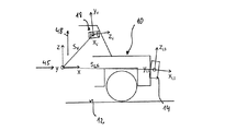
図1及び2において、面12上に位置する車両10は、車両10の前側で車両10の前方領域を監視するために車両10に取り付けられる、本例ではレーザスキャナである距離画像センサ14と、車両10に取り付けられかつ単眼ビデオカメラ18を有するビデオシステム16とを搭載している。車両10には、レーザスキャナ14及びビデオシステム16に関連づけられるデータ処理デバイス20がさらに位置づけられる。第1の較正オブジェクト22l及び22r、及び第2の較正オブジェクト24、24'及び24''も、車両10の前及び側方の進行方向に位置づけられる。
1 and 2, a
レーザスキャナ14は、図1に一部のみが示されている、180゜を幾分超える角度をカバーする検出レンジ26を有する。図1において、検出レンジ26は、説明を分かりやすくするために単に略示され、特に半径方向の表示が短縮されている。検出レンジは、図2に略示されているように、互いに、かつレーザスキャナ14に対して予め設定された既知の位置を採用する4つのファン状の走査エリア28、28'、28''及び28'''を含む。対応するレーザスキャナは、例えば先に述べたドイツ国特許出願に開示されている。較正オブジェクト22l及び22rと24、24'及び24''は、検出レンジ26内に位置づけられている。
The
レーザスキャナ14は、その検出レンジ26を基本的には既知方法により、一定の角速度で揺動されかつ検出レンジ26の中心へと揺動される位置において車両がその上に位置する面12に垂直である略矩形の細長い断面を有するパルス・レーザビーム30を使用して走査する。検出は、レーザビーム30の揺動動作に調和された方法で回転式に、中心角αiの周りの一定の角度範囲において一定の時間間隔Δtで時間τiにおいて行われ、レーザビーム30が例えば較正オブジェクト22l及び22r及び24、24'及び24''のうちの1つである物体の点32から、又は領域から反射されるかどうかが決定される。これにより、指数iは1から検出レンジ26内の角度範囲数まで増加する。これらの角度範囲のうち、図1は中心角αiに対応する1つの角度範囲だけを示している。この関連において、この角度範囲は、より明確な表示を目的として誇張的に大きく示されている。この関連において、物体から投げ返される光は、その受信範囲が対応的に同時に揺動される対応的に位置合わせされた4つの検出器によって受信される。従って結果的に、4つの走査エリア28、28'、28''及び28'''において走査が行われる。レーザビーム30に沿った断面と走査平面の断面とは既知の僅かな角度で互いに対して傾斜され、その大きさは揺動角度に依存しかつ既知である。従って検出レンジ26は、図2から認識できるように、レーザビーム30の広がりに関係なく二次元的な4つの走査エリア28、28'、28''及び28'''を含む。
The
オブジェクトポイントi(図1における例では、走査エリアjにおけるオブジェクトポイント32)の距離画像センサとの間隔dijは、レーザスキャナ14によりレーザビーム・パルスの経過時間を参照して決定される。従ってレーザスキャナ14は、走査エリアjに加えて、角度αi及びこの角度で検出される距離dijをオブジェクトポイント32に対応する距離画像点における座標として、即ち極座標におけるオブジェクトポイント32の位置として検出する。従って、オブジェクトポイントは各距離画像点に関連づけられる。
The distance d ij between the object point i (the
走査中に検出される距離画像点の集合は、本出願の意味合いにおける距離画像を形成する。 The set of range image points detected during scanning forms a range image in the sense of this application.
レーザスキャナ14は、走査の時間シーケンス及び対応する距離画像が発生するように、第1の検出レンジ26を順次走査で個々に走査する。
The
ビデオシステム16の単眼ビデオカメラ18は、CCDエリアセンサ34と画像形成システムとを有する、本例では車両10のフロントガラスの裏側のバックミラー領域に取り付けられる従来型の白黒ビデオカメラである。これが有する画像形成システムは、図1及び2では単純なレンズ36として略示されているが、実際にはレンズ系より成り、ビデオシステムのビデオ検出領域40からの入射光の画像をCCDエリアセンサ34上へ形成する。ビデオカメラ18の光軸38は、レーザスキャナ14の走査エリア28、28'、28''及び28'''に対して、図2には誇張して大きく示されているが僅かな角度で傾斜される。
The
CCDエリアセンサ34は、行列状に配置される光検出素子を有する。光検出素子の信号は読み出され、もともと行列内の光検出素子の位置又は光検出素子の別の特性を含み、かつ各場合毎に対応する光検出素子から受信される光の強度に対応する強度値を含むビデオ画像点を有するビデオ画像が形成される。この実施形態では、ビデオ画像は距離画像がレーザスキャナ14によって検出される速度と同じ速度で検出される。
The
例えば較正オブジェクト24であるオブジェクトから到来する光は、画像形成システム36を介してCCDエリアセンサ34上へ画像化される。これは、図1及び2において、例えば較正オブジェクト24であるオブジェクトの輪郭として短い破線で略示されている。
Light coming from an object, for example a
ビデオカメラ18のカメラモデルにより、行列形式に配置された光検出素子により形成されかつオブジェクトポイントが画像化されるCCDエリアセンサ34の位置は、CCDエリアセンサ34と画像形成システム36との距離、画像形成システム36の位置及び画像形成特性(例えば焦点幅)、及び較正オブジェクト上のオブジェクトポイント(例えばオブジェクトポイント32)の位置から計算可能である。
The position of the
監視領域42は、図1において点線で略示され、各々レーザスキャナ14の検出レンジ26とビデオシステム16の検出領域40との共通部分によって与えられる。
The monitoring area 42 is shown schematically in dotted lines in FIG. 1 and is provided by the intersection of the
データ処理デバイス20は、レーザスキャナ14及びビデオシステム16の画像を処理するために供給され、この目的に沿ってレーザスキャナ14及びビデオシステム16へ接続される。データ処理デバイス20は、とりわけ、検出される距離画像及びビデオ画像を評価するようにプログラムされるデジタル信号プロセッサと、デジタル信号プロセッサに接続されるメモリ・デバイスとを有する。別の実施形態では、データ処理デバイスは、データ処理デバイスに格納されるコンピュータ・プログラムを検出される画像を評価するように設計する従来のプロセッサも有することが可能である。
A data processing device 20 is provided to process the images of the
第1の較正オブジェクト22l及び22rと第2の較正オブジェクト24、24'及び24''は基準線44に対して鏡面対称式に配置され、較正オブジェクト24の中央の1つが基準線44上に配置されている。車両10は、その長手軸45を基準線44に平行に、かつ特には基準線44より上にして配置される。
The first calibration objects 22 l and 22 r and the second calibration objects 24, 24 ′ and 24 ″ are arranged in mirror symmetry with respect to the reference line 44, and one center of the
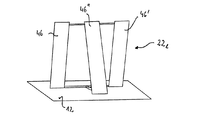
図1及び3に示すように、同じように設計されている較正オブジェクト22l及び22rは、レーザスキャナ14及び基準線44に対して本例では基準線44の左右45゜の角度で配置され、面12に対して本例では約30゜及び−30゜の所定の角度で傾斜された類似する大きさの3つの平らな第1の較正面46、46'及び46''を含む。この関連において、第1の較正面46及び46'は互いに対して平行に配置され、第1の較正面46''は車両の面12の法線又は垂直軸に対して第1の較正面46及び46'と同じ角度を異なる符号で張られており、よって側面図では切り妻屋根又は二等辺三角形に似た形状がもたらされる(図9参照)。三角形の高さH、及び面12おける第1の較正面46、46'及び46''の第1の較正面の傾斜方向の間隔Bは既知である。第1の較正面46、46'及び46''は、レーザスキャナ14による検出に際して順次距離画像点が較正オブジェクト上に、即ち第1の較正面46、46'及び46''のうちの1つの前でも後でもなくその上に、間隙なしに存在するように互いに隣接して配置される。
As shown in FIGS. 1 and 3, similarly designed calibration objects 22 l and 22 r are arranged at an angle of 45 ° to the left and right of the reference line 44 in this example with respect to the
同様に同じ設計である第2の較正オブジェクト24、24'及び24''は各々、面12に対して直交する、よって車両の垂直軸48に平行であって端52で互いに交差する、互いに傾斜されている2つの第2の平坦な較正面50及び50'を含む(図1及び3参照)。
Similarly, the second calibration objects 24, 24 ′ and 24 ″ of the same design are each inclined relative to the
本例ではチェスボート状のパターンである既知の較正機能を有する第3の平坦な較正面54は、較正オブジェクト24、24'及び24''上で第2の較正面50及び50'と対称に、どの場合も面12に直交する端52上に配置される。チェスボード状のパターンの中心点は、面12に直交する端52の延長線上の既知の高さにある。
A third
以下で説明する本発明の好適な実施形態による較正方法においては、複数の座標系を使用する(図5A、5B及び6参照)。 In the calibration method according to a preferred embodiment of the present invention described below, a plurality of coordinate systems are used (see FIGS. 5A, 5B and 6).
レーザスキャナ14には軸xLS、yLS、zLSを有するレーザスキャナのデカルト座標系が関連づけられ、距離画像点の座標はレーザスキャナ座標系において与えられる。オブジェクトの座標は、さらに、ビデオカメラ18に固定的に関連づけられる軸xV、yV、zVを有するカメラのデカルト座標系において特定することが可能である。最後に、x軸が車両の長手軸45と同軸を成しかつy軸及びz軸が各々車両の横軸55及び車両の垂直軸48に平行して延びる、車両のデカルト座標系が供給される(図3A及び3B)。レーザの座標系における座標は指数LSで指示され、カメラの座標系における座標は指数Vで指示されているが、車両の座標系における座標は指数を持たない。
Associated with the
レーザスキャナ座標系の原点は、車両座標系の原点に対して、レーザスキャナ14の車両10上への据付け位置によって決定されかつ既知であるベクトルsLSだけシフトされている。
The origin of the laser scanner coordinate system is shifted relative to the origin of the vehicle coordinate system by a known vector s LS determined by the position of the
カメラ座標系の原点は、車両座標系の原点に対して、ビデオカメラ18の車両10上への据付け位置によって決定されかつ既知であるベクトルsVだけ相応にシフトされている。
The origin of the camera coordinate system is correspondingly shifted with respect to the origin of the vehicle coordinate system by a known vector s V determined by the installation position of the
レーザスキャナ座標系及びカメラ座標系の座標軸は、車両座標系の対応する軸に対して回転されるのが一般的である。レーザスキャナ座標系の場合、走査エリアもまた車両の長手軸及び横軸に対して同じように傾斜される。方向性は、ピッチ角θLS及びθVとロール角φLS及びφVにより記述される。さらに、両座標系は各々ヨー角ψLS及びψVだけ回転される。 Generally, the coordinate axes of the laser scanner coordinate system and the camera coordinate system are rotated with respect to the corresponding axes of the vehicle coordinate system. In the case of a laser scanner coordinate system, the scanning area is also tilted in the same way with respect to the longitudinal and lateral axes of the vehicle. Directionality is described by pitch angles θ LS and θ V and roll angles φ LS and φ V. Further, both coordinate systems are rotated by yaw angles ψ LS and ψ V, respectively.
より正確に言えば、レーザスキャナ座標系は車両座標系から進み、まずベクトルsLSによる平行移動が実行され、次にシフトされたz軸を中心とするヨー角ψLSによる回転、シフトされかつ回転されたx軸を中心とするロール角しφLSによる回転及び最後にシフトされかつ回転されたy軸を中心とするピッチ角θLSによる回転が相次いで実行される(図6参照)。 More precisely, the laser scanner coordinate system proceeds from the vehicle coordinate system and is first translated by the vector s LS and then rotated, shifted and rotated by the yaw angle ψ LS about the shifted z axis. The rotation by the roll angle φ LS centered on the x-axis and the rotation by the pitch angle θ LS centered on the last shifted and rotated y-axis are successively performed (see FIG. 6).
車両座標系に座標X、Y、Zを有する点の座標XLS、YLS、ZLSへの変換は、エントリrmnを有する回転行列Rと成分sLSx、sLSy及びsLSzを有する平行移動ベクトルsLSを用いた同次変換により次のように記述されることが可能である。

平行移動ベクトルsLSの成分は、車両座標系におけるレーザ座標系の原点の座標に対応する。 The component of the translation vector s LS corresponds to the origin coordinate of the laser coordinate system in the vehicle coordinate system.
回転行列Rは、x軸を中心とする回転に関する基本回転行列、
回転の順序は所望される通りに選択可能であるが、較正に関しては選択されたとおりに維持されなければならない。この点で、順序は正確にピッチ角、ロール角及びヨー角を規定する。本例では、回転はまずz軸を中心に行われ、次いでx軸を中心に、最後にy軸を中心にして行われる(図6参照)。よって、結果は下記のようになる。
従って、レーザスキャナ14及び走査エリア28、28'、28''及び28'''の位置合わせはピッチ角、ロール角及びヨー角の列挙によって記述可能であり、ピッチ角及びロール角は車両座標系に対する、又は長手軸45及び横軸55の各々を含む平面に対する方向性を再現する。
Therefore, the alignment of the
較正の間、座標及びデータはレーザスキャナ座標系に存在することから、この座標系は始点として作用する。この座標は、段階的に車両座標系へと変換される。 During calibration, this coordinate system serves as a starting point because coordinates and data are present in the laser scanner coordinate system. These coordinates are converted step by step into the vehicle coordinate system.
この点に関しては、車両座標系からベクトルSLSだけ平行移動しかつ平行移動されたz軸を中心としてヨー角ψLSだけ回転して得られる中間座標系が使用される。この座標系における座標は、指数zsによって示される。ピッチ角及びロール角は、走査エリア、即ちレーザ座標系のxLS−yLS平面の車両及び/又は中間座標系に対する方向性の決定からもたらされる。 With respect to this point, an intermediate coordinate system obtained by translating from the vehicle coordinate system by the vector S LS and rotating by the yaw angle ψ LS around the translated z axis is used. The coordinates in this coordinate system are indicated by the index zs. The pitch and roll angles result from determining the direction of the scan area, ie, the x LS -y LS plane of the laser coordinate system, relative to the vehicle and / or the intermediate coordinate system.
ヨー角は、レーザスキャナ14の基準方向、例えばx−y又はxZS−yZS平面におけるxLS軸の回転をもたらし、引き続き必要な回転として最後に決定される。
The yaw angle results in rotation of the x LS axis in the reference direction of the
カメラ座標系における座標の車両座標系における座標への変換は、対応するピッチ角、ロール角及びヨー角を使用して同様に行われる。 Conversion of coordinates in the camera coordinate system to coordinates in the vehicle coordinate system is similarly performed using the corresponding pitch angle, roll angle, and yaw angle.
本発明方法においては、ビデオ画像の像点は、レーザスキャナ14によって検出されるオブジェクトポイント及び/又は対応する距離画像点に関連づけられる。このために要求されるカメラの画像形成特性を記述するためには、マットディスク・モデルが使用される(図7参照)。本例ではビデオ画像が処理に先立って歪を除去すべく相応に処理されるため、これで十分である。
In the method of the present invention, the image points of the video image are associated with object points and / or corresponding range image points detected by the
画像形成システム36の焦点に原点が存在するカメラ座標系におけるオブジェクト(xV,yV,zV)は、焦点から距離fを隔てて存在する、軸u及びvを有するデカルト座標系を画定している画像形成平面上へ投射される。
An object (x V , y V , z V ) in the camera coordinate system where the origin is at the focal point of the
カメラ座標系において座標XV、YV、ZVを有するオブジェクトポイントのピクセル単位の像点座標(u,v)は、ビームの法則を使用して像点で引用される焦点幅fu及びfv及びマットディスクを伴うzV軸の交点(u0,v0)により下記のように列挙されることが可能である。
較正は、本発明の好適な実施形態の方法により、下記のように実行される。 Calibration is performed as follows by the method of the preferred embodiment of the present invention.
第1のステップにおいて、車両及び較正面、即ち較正本体22l及び22r及び同じく24、24'及び24''は、中央の第2の較正本体24'の端52が車両の長手軸45上、従って車両座標系のx軸上に存在するように互いに対して配置される。さらに、2つの第1の較正本体22l及び22rは、車両の長手軸45の両側で向かい合うように同軸に対して約45゜の角度で配置される。
In the first step, the vehicle and calibration surfaces,
次のステップでは、情景の距離画像及びビデオ画像が検出され、事前処理される。事前処理の間、好適には例えば歪を除去するためにビデオ画像データの調整を実行することができる。次に、実際の距離画像及び実際のビデオ画像が後の利用のために格納される。 In the next step, the distance image and video image of the scene are detected and preprocessed. During the preprocessing, adjustments of the video image data can be performed, preferably to remove distortion, for example. The actual distance image and the actual video image are then stored for later use.
次の諸ステップでは、まず検出された距離画像を基礎とするレーザスキャナ14の方向性の決定が行われ、ピッチ角及びロール角が決定される。
In the next steps, the directionality of the
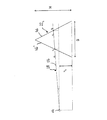
あるステップでは、レーザスキャナ14から走査エリア内へ放射状に進む走査ビーム又は仮想ビーム56の傾斜が、少なくとも2つの較正オブジェクト22l及び22rに関して決定される(図8及び9参照)。これについては、走査エリア28に関連して説明する。
In one step, the tilt of the scanning beam or
このために、まず、レーザスキャナ14の方へ傾斜された各々2つの第1の較正面46、46'上の領域に対応する距離画像点から、各々較正オブジェクト22l及び22rの双方について後部基準点Phの位置が求められる。較正面の端上の距離画像点は、この目的のためには考慮されない。これに対応して、前部基準点Pvの位置が、レーザスキャナ14から遠方向に傾斜された個々の較正面46''の領域に対応する距離画像点から決定される。各々の場合の基準点Ph及びPvは、走査エリア28が対応する較正面46、46'及び46''と交わる高さを表す。さらにこれらは、距離画像点の後部基準点Phに関して決定される回帰直線に対しかつ距離画像点の前部基準点Pvに関して求められる回帰直線に対して直交しかつレーザスキャナ14又はレーザスキャナ座標系の原点を通って延びる仮想走査ビーム56上に存在する(図8参照)。
To this end, first the distance image points corresponding to the regions on each of the two first calibration surfaces 46, 46 ′ tilted towards the
何れの場合も、回帰直線(図8参照)は後部基準点Phに関する距離画像点57から、及び前部基準点Pvに関するそれらから例えば直線回帰によって決定される。次に、回帰直線とこれらに直交しかつレーザスキャナ座標系の原点を通って延びる仮想ビーム56との交点が、各々後部及び前部基準点Ph及びPvとして決定される(図8参照)。基準点Ph及びPvの位置のこの種の決定を介して、距離画像の検出中の角度決定における不正確さの影響は格段に低く維持され、又は除去される。
In either case, (see FIG. 8) regression line from the distance image points 57 about the rear reference point P h, and is determined therefrom, for example by linear regression about a front reference point P v. Next, the intersection of the regression line and the
こうして、これらの基準点Ph及びPvに関して、レーザスキャナ座標系の原点からの距離dh及びdv、及びレーザ座標系における座標から計算されるべき対応する旋回角度αが既知となる、即ち距離画像点から容易に求められる。 Thus, in these reference points P h and P v, the distance d h and d v from the origin of the laser scanner coordinate system, and the turning angle α corresponding to be calculated from the coordinates in the laser coordinate system is known, i.e. It is easily obtained from the distance image point.
前部及び後部基準点はさらに、面12から上、即ち車両座標系から上に、レーザスキャナ14即ち走査エリアが車両座標系のx−y平面に対して正確に平行に延びない場合に各々較正面46、46'及び46''の異なる傾斜を原因として生じる個々の高さを有する。h0が、車両内のレーザスキャナ14の据付け位置から既知である、レーザスキャナ座標系即ち走査エリアの原点の車両座標系からのz方向における間隔を表していれば、走査エリア28における仮想ビーム56の傾斜βに関して、図9から次のような式を導出することができる。
この式は、較正面46、46'及び46''及び車両10がこの関係式において予め正確に設定された相対位置を一切守る必要がないように、較正面46、46'及び46''のレーザスキャナ14からの所定の距離を含んでいない。
This equation is used for the calibration surfaces 46, 46 'and 46 "and for the calibration surfaces 46, 46' and 46" so that the
従って、本方法においては、この式は角βについて、数値的に発生し得るdh、dv、H、B及びh0の既知の又は決定される値を使用して解かれる。但し代替として、これらの値は解析的に得られる上記式の解において使用されることも可能である。 Thus, in the present method, this equation is solved for the angle β using known or determined values of d h , d v , H, B and h 0 that can be numerically generated. However, as an alternative, these values can also be used in the solution of the above equation obtained analytically.
後続ステップでは、走査エリア28がレーザスキャナ座標系のxLS−yLS平面において伸長しない場合、仮想ビームの旋回角度αにより設定される方向へのレーザスキャナ座標系の対応する傾斜は、決定された角βを値β'=β−ε(α)に置換することにより、小さいロール角について近似的に決定可能である。但しε(α)は、レーザスキャナ14及び走査エリア28について既知である、走査エリア28に沿ったビームとレーザスキャナ座標系の旋回角度αにおけるxLS−yLS平面との間で使用される傾斜角を示す。
In a subsequent step, if the
従ってこの後、β'は、レーザスキャナ座標系における方向αに沿った対応する較正オブジェクトに関するレーザスキャナ座標系の傾斜を示す。 Therefore, after this, β ′ indicates the tilt of the laser scanner coordinate system with respect to the corresponding calibration object along the direction α in the laser scanner coordinate system.
従って、走査エリア28の方向αl及びαrにおける傾斜βl及びβrの個々の角度は、基準線44の左右の2つの較正面22l及び22rに関するレーザスキャナ座標系において求められ、これはさらなるステップにおいて使用可能である。
Thus, the individual angles of inclination beta l and beta r in the direction alpha l and alpha r scan area 28 is determined in the laser scanner coordinate system for the two
後続ステップでは、中間座標系及び/又は車両座標系に対する角度θLS及びφLSが、レーザスキャナ座標系における方向αl及びαrの2つの傾斜角βl'及びβr'から計算される。先に既に述べたように、レーザ座標系は中間座標系から進み、中間座標系はまずxZS軸を中心に角度φLSだけ回転され、次に回転されたyZS軸を中心に角度θLSだけ回転される。 In a subsequent step, the angles θ LS and φ LS with respect to the intermediate coordinate system and / or the vehicle coordinate system are calculated from the two tilt angles β l ′ and β r ′ in the directions α l and α r in the laser scanner coordinate system. As previously already mentioned, the laser coordinate system proceeds from the intermediate coordinate system, the intermediate coordinate system is first rotated x ZS axis by an angle phi LS centered, angle around the y ZS shaft that is rotated next theta LS Only rotated.
このために使用される公式は、例えば次のようにして求めることができる。各々方向αl及びαrへ中間座標系のxZS−yZS平面に平行に傾斜されて延びる、即ち各々レーザスキャナ座標系のxZS−yZS平面に対して傾斜角βl'及びβr'で延びるレーザスキャナ座標系における2つの単位ベクトルを決定する。これらの単位ベクトルのベクトル積は、長さが正確に2つの単位ベクトル間の角度の正弦である中間座標系のzLS方向のベクトルに相当する。レーザスキャナ座標系の座標において計算されるベクトル積を、結果が既知である中間座標系に変換する。変換方程式から次のように、ロール角φLSについて、式、
ピッチ角及びロール角の値は各々計算された旋回角度αl及びαrに依存するが、基準点は本質的に距離情報を基礎として求められることから、導出に使用されるのは本質的に距離情報である。 The pitch angle and roll angle values depend on the calculated turning angles α l and α r respectively, but the reference point is essentially determined on the basis of the distance information, so that it is essentially used for the derivation. Distance information.
本方法に必要な作業は、これらの公式に対応する値を代入することだけである。 The only work required for this method is to substitute values corresponding to these formulas.
次の諸ステップでは、残りのヨー角ψLSが車両の長手軸45上に配置される第2の較正オブジェクト24を使用して求められる(図11及び12参照)。
In the next steps, the remaining yaw angle ψ LS is determined using the
このために、まず、第2の較正面50及び50'上の2つの輪郭線の交点によって与えられる第2の較正オブジェクト24の基準点58が求められる。輪郭線は、第2の較正面上で検出される距離画像点により、較正面の既知の形状、即ち走査エリアと第2の較正面50及び50'との共通部分を考慮して決定される。
For this purpose, first a reference point 58 of the
基準点58は、走査エリア28と平らな第2の較正面50、50'の真っ直ぐな交線との共通部分を介して、かつ第2の較正面50、50'上に広がる領域の距離画像点60を介する輪郭線に対応する回帰直線62の交点によってもたらされる。この目的に沿って、回帰直線は、レーザ座標系において対応する距離画像点62を介して直線回帰により配置される。次には、直線回帰の交点が求められる。これを行なう際に、端上の距離画像点はやはり使用されない(図12参照)。
The reference point 58 is a distance image of a region extending through the intersection of the
こうして求められた基準点58の座標は、次に中間座標系における座標において決定されるロール角の値及びピッチ角の値を使用して変換される。ヨー角を決定するためには、車両座標系のy方向における基準点58の位置は既知であるという事実、即ち端は真っ直ぐな基準線44の上に、よって車両の長手軸即ちx軸上に直接存在し、故にy座標0を有するという事実が利用される。x座標はXで示されるが、次のステップでは何の役目も果たさない。次には、中間座標系における基準点の座標(XZS,YZS)と車両座標系における座標(X,0)との間の関係式、
本方法においてこの方程式は、値ψLSについて、傾斜の決定と同様にして数値的又は解析的に解かれる。 In the present method, this equation is solved numerically or analytically for the value ψ LS in the same way as the determination of the slope.
従って、レーザスキャナ14の車両座標系に対する方向性は、完全に認識される。
Therefore, the directionality of the
別の実施形態では、角εが存在するレーザスキャナ座標系のxLS−yLS平面に垂直な平面と、角βが決定される車両座標系のx−y平面に垂直な平面との間の実際の角度がより正確に考慮される。この目的に沿って、ピッチ角及びロール角の出発値が第1の実施形態によって導出される値を手始めに計算される。次には、これらの値を使用して、角εが存在する平面及び角βが決定される車両座標系のx−y平面に垂直な平面の位置合わせが既知の三角法の関係式によって決定される。これで、既知の位置合わせにより、角ε又はβ'は第1の近似値まで決定されることが可能である。これを基礎として、ピッチ角及びロール角の新たな値が求められる。位置合わせは反復により極めて正確に決定されることが可能であり、反復においてピッチ角及びロール角の値は各々最終の値へと変わる。 In another embodiment, between the plane perpendicular to the x LS -y LS plane of the laser scanner coordinate system where the angle ε is present and the plane perpendicular to the xy plane of the vehicle coordinate system where the angle β is determined. The actual angle is taken into account more accurately. For this purpose, the starting values of the pitch angle and roll angle are calculated starting from the values derived by the first embodiment. Next, using these values, the alignment of the plane in which the angle ε exists and the plane perpendicular to the xy plane of the vehicle coordinate system in which the angle β is determined is determined by a known trigonometric relation. Is done. Now, with known registration, the angle ε or β ′ can be determined up to the first approximation. Based on this, new values of the pitch angle and roll angle are obtained. The alignment can be determined very accurately by iteration, with the pitch angle and roll angle values each changing to a final value in the iteration.
次には、レーザスキャナ14の既知となった方向性を基礎として、ビデオカメラ18のレーザスキャナ14に対する方向性、延ては車両座標系に対する方向性が発生し得る。
Next, based on the known directionality of the
この目的に沿って、車両座標系における少なくとも2つの較正機能の位置がレーザスキャナ14により検出された距離画像を基礎として求められ、車両座標系に変換される。これらの較正機能は、車両座標系におけるビデオカメラ18の既知の位置及び車両座標系からカメラ座標系への変換のための仮想回転角を使用して変換される。次には、カメラ・モデルにより、距離画像を基礎として決定される対応する較正機能の位置がビデオ画像において求められる。
In accordance with this purpose, the positions of at least two calibration functions in the vehicle coordinate system are obtained on the basis of the distance image detected by the
距離画像により求められたビデオ画像におけるこれらの位置は、ビデオ画像において実際に決定された位置とu−v平面において比較される。 These positions in the video image determined by the distance image are compared in the uv plane with the positions actually determined in the video image.
例えば共役勾配を使用するプロセスである数値的な最適化プロセスを使用して、車両座標系とカメラ座標系との間の座標変換のための回転角は、ビデオ画像における較正機能の実際の位置と距離画像を基礎として予測された位置との間の平均二乗間隔が最小化されるように、又は回転角の絶対又は相対変化の大きさが所定のしきい値より下に下がるように最適化される。 For example, using a numerical optimization process, which is a process that uses conjugate gradients, the rotation angle for coordinate transformation between the vehicle coordinate system and the camera coordinate system is calculated as the actual position of the calibration function in the video image. Optimized to minimize the mean square distance from the predicted position based on the distance image, or to reduce the magnitude of absolute or relative change in rotation angle below a predetermined threshold The
本例では、第3の較正面54又は較正・パネル上のパターンの通過点が、次に較正機能として使用される。位置は、この関連において距離画像から決定され、車両座標系のx−y平面上の基準点の位置が車両座標系において求められ、通過点の面12からの、又は車両座標系のx−y平面からの既知の間隔のz座標として使用される。
In this example, the
通過点は、単にビデオ画像において、予め設定されたテンプレートに関連して求められることが可能である。 The passing point can be determined simply in the video image in relation to a preset template.
レーザスキャナ及びビデオカメラの較正もまた、互いに独立して実行されることが可能である。 Calibration of the laser scanner and video camera can also be performed independently of each other.
別の実施形態では、仮想ビームの決定された傾斜を基礎とするピッチ角及びロール角の導出において、レーザスキャナ座標系上の前部又は後部基準点の座標及び同じく車両座標系における位置のz成分が求められる。次には、座標変換を基礎として、ピッチ角及びロール角を求めることができる。 In another embodiment, in the derivation of the pitch angle and roll angle based on the determined tilt of the virtual beam, the coordinates of the front or rear reference point on the laser scanner coordinate system and also the z component of the position in the vehicle coordinate system Is required. Next, the pitch angle and the roll angle can be obtained based on coordinate transformation.
さらなる実施形態では、車両10の生産ライン内で平行に延びる壁が、その上で平行に延びるネットライン66がビデオカメラ16の位置合わせの較正のための較正機能として適用される第2の較正面64として使用される(図12及び13参照)。
In a further embodiment, a second calibration surface in which the parallel extending walls in the production line of the
ヨー角を決定するために、第2の較正面64上を延びる回帰直線及びヨー角に対応する車両の長手軸45に対するそれらの角度が再度、第2の較正面64上の距離画像点を使用して決定される。この場合も使用されるのは本質的に距離データであり、よって角度決定における誤差は重大ではない。
To determine the yaw angle, the regression line extending over the
第3の実施形態では、各々第1の較正面46''と同様に傾斜されている、車両の長手軸を横断してもう一方から離隔された2つの第1の較正面のみが使用される。 In the third embodiment, only two first calibration surfaces are used, each inclined in the same manner as the first calibration surface 46 '' and spaced from the other across the longitudinal axis of the vehicle. .
第1の較正面46''の各々について、第1の実施形態に従って決定された車両座標系のそのz方向における基準点Pvの位置は、個々の較正面46''のレーザスキャナ14からの所定の既知の距離Dを使用して求めることができる(図14参照)。レーザスキャナ座標系では、この点はzLS座標0を有する。次式、
従って、xLS−yLS平面の3つの点、較正面の2つの基準点及びレーザスキャナ座標系の原点が既知となり、これらからピッチ角及びロール角を決定することができる。 Therefore, the three points on the x LS -y LS plane, the two reference points on the calibration surface, and the origin of the laser scanner coordinate system are known, and the pitch angle and roll angle can be determined from these.
第4の実施形態では、2つの走査エリアにおける距離画像点が先程説明した較正面と共に使用され、これにより、対応する仮想ビームの面12に対する傾斜が既知となり、これからピッチ角及びロール角を求めることができる。
In the fourth embodiment, the distance image points in the two scanning areas are used with the calibration surface described above, so that the corresponding inclination of the virtual beam with respect to the
10…車両
12…面
14…レーザスキャナ
16…ビデオシステム
18…ビデオカメラ
20…データ処理デバイス
22l,22r…第1の較正オブジェクト
24,24',24''…第2の較正オブジェクト
26…検出レンジ
28,28',28'',28'''…走査エリア
30…レーザビーム
32…オブジェクトポイント
34…CCDエリアセンサ
36…画像形成システム
38…光軸
40…ビデオ検出レンジ
42…監視レンジ
44…基準線
45…車両の長手軸
46,46',46''…第1の較正面
48…車両の垂直軸
50,50'…第2の較正面
52…端
54…第3の較正面
55…車両の横軸
56…仮想走査ビーム
57…距離画像点
58…基準点
60…距離画像点
62…回帰直線
64…第2の較正面
66…ネットライン
10 ...
Claims (23)
前記走査エリア(28,28',28'',28''')又は距離画像センサ(14)の車両(10)に対する位置合わせに関して対応する距離画像を検出することが可能であるような、
車両(10)に取り付けられる電磁放射線のための該距離画像センサ(14)を少なくとも部分的に較正する方法であって、
前記距離画像センサ(14)と少なくとも1つの較正面(46,46',46'',50,50')上の領域との距離が本距離画像センサ(14)によって求められ、かつ、
求められた前記距離を使用して、前記位置合わせを少なくとも部分的に記述するパラメータの値が決定される方法。 It is possible to scan the detection range (26) along at least one scanning area (28, 28 ', 28'',28'''); and
A corresponding distance image can be detected with respect to the alignment of the scanning area (28, 28 ′, 28 ″, 28 ′ ″) or the distance image sensor (14) with respect to the vehicle (10),
A method for at least partially calibrating the range image sensor (14) for electromagnetic radiation attached to a vehicle (10) comprising:
A distance between the distance image sensor (14) and a region on the at least one calibration surface (46, 46 ′, 46 ″, 50, 50 ′) is determined by the distance image sensor (14); and
A method wherein a value of a parameter that at least partially describes the alignment is determined using the determined distance.
上記距離画像センサ(14)の座標系における座標が、上記走査エリア(28,28',28'',28''')に関連づけられる検出された距離画像の距離画像点に関して決定されること、
前記座標が上記位置合わせの少なくとも部分的な決定に使用されること、
を特徴とする先行する任意の請求項に記載の方法。 The distance image sensor (14) with known position and / or alignment of the scanning area (28, 28 ′, 28 ″, 28 ′ ″) with respect to the coordinate system of the distance image sensor (14) is calibrated. That
Coordinates in the coordinate system of the distance image sensor (14) are determined with respect to the distance image points of the detected distance image associated with the scanning area (28, 28 ′, 28 ″, 28 ′ ″);
The coordinates are used for at least partial determination of the alignment;
A method according to any preceding claim characterized by:
上記距離画像センサ(14)の位置合わせを少なくとも部分的に再現するパラメータの値が、上記走査エリア(28,28',28'',28''')に関連づけられる値から決定されること、
を特徴とする請求項3又は請求項3及び4に記載の方法。 For each of the scanning areas (28, 28 ′, 28 ″, 28 ′ ″), individual scanning areas (28, 28 ′, 28 ″, 28 ′) of parameters that at least partially reproduce the alignment. ″) Is determined from the distance of the detection area on the calibration surface (46, 46 ′, 46 ″, 50, 50 ′) to the distance image sensor (14);
A value of a parameter that at least partially reproduces the alignment of the distance image sensor (14) is determined from a value associated with the scanning area (28, 28 ′, 28 ″, 28 ′ ″);
5. A method according to claim 3 or claims 3 and 4.
特にはピッチ角である上記方向性を少なくとも部分的に再現するパラメータの値が、上記距離画像センサ(14)によって検出される領域の検出距離から該領域の傾斜に従い決定されること、
を特徴とする先行する任意の請求項に記載の方法。 The areas of the calibration surface (46, 46 ′, 46 ″) are respectively the scanning area (28, 28 ′, 28 ″, 28 ″ ′) or the vehicle (10) of the distance image sensor (14). Tilted in a predetermined manner with respect to the longitudinal or vertical axis of the vehicle for at least partial determination of directionality, in particular pitch angle
In particular, the value of the parameter that at least partially reproduces the directionality that is the pitch angle is determined according to the inclination of the region from the detection distance of the region detected by the distance image sensor (14),
A method according to any preceding claim characterized by:
上記走査エリア(28,28',28'',28''')又は上記距離画像センサ(14)の特にはピッチ角である方向性を少なくとも部分的に再現するパラメータの値が、上記較正面(46,46',46'')の決定された距離を使用して決定されること、
を特徴とする先行する任意の請求項に記載の方法。 The distance of the calibration surface (46, 46 ′, 46 ″) from the distance image sensor (14) in the range of the scanning area (28, 28 ′, 28 ″, 28 ′ ″) is the calibration surface. Being determined from at least two detection distances in the region (46, 46 ′, 46 ″);
The value of the parameter that at least partially reproduces the directionality of the scanning area (28, 28 ′, 28 ″, 28 ′ ″) or the distance image sensor (14), in particular the pitch angle, is the calibration plane. Being determined using the determined distance of (46, 46 ′, 46 ″),
A method according to any preceding claim characterized by:
上記距離画像センサ(14)と上記走査エリア(28,28',28'',28''')に近接する上記較正面(46,46',46'')上の領域との距離が、該距離画像センサ(14)によって決定されること、
決定される前記距離の差が、上記走査エリア(28,28',28'',28''')又は上記距離画像センサ(14)の特にはピッチ角である方向性を少なくとも部分的に再現するパラメータの値の決定に使用されること、
を特徴とする先行する任意の請求項に記載の方法。 Two calibration planes (46, 46 ′, 46 ″) arranged adjacent to each other in a predetermined position for at least partial determination of directionality, in particular the pitch angle, used for calibration The calibration surface area to be used is inclined with respect to the longitudinal or vertical axis of the vehicle in different predetermined ways;
The distance between the distance image sensor (14) and the area on the calibration surface (46, 46 ′, 46 ″) adjacent to the scanning area (28, 28 ′, 28 ″, 28 ′ ″) is Being determined by the distance image sensor (14);
The determined distance difference at least partially reproduces the directionality of the scanning area (28, 28 ′, 28 ″, 28 ′ ″) or the distance image sensor (14), in particular the pitch angle. Used to determine the value of the parameter to be
A method according to any preceding claim characterized by:
上記較正面(50,50')上の少なくとも2つの領域の位置が上記距離画像センサ(14)によって決定されること、
前記回転の角度を再現する特にはヨー角であるパラメータの値が、求められる前記位置に従い決定されることを特徴とする先行する任意の請求項に記載の方法。 A reference direction in the scanning area (28, 28 ′, 28 ″, 28 ′ ″) or a reference direction of the distance image sensor (14), at least approximately around the vertical axis of the vehicle or the scanning area ( 28, 28 ′, 28 ″, 28 ′ ″) to determine rotation about a normal to at least one calibration plane (50, 50 ′), the vehicle (10) reference That the shape and alignment with respect to the direction are determined in advance,
The position of at least two regions on the calibration surface (50, 50 ') is determined by the distance image sensor (14);
Method according to any preceding claim, characterized in that the value of a parameter that reproduces the angle of rotation, in particular the yaw angle, is determined according to the position that is sought.
上記較正面(50,50')の各々の上の少なくとも2つの領域の位置が、いずれの場合も上記距離画像センサ(14)によって決定されること、
上記パラメータの値が上記位置に従い決定されること、
を特徴とする請求項14に記載の方法。 Two calibration surfaces (50, 50 ') are used which are pre-determined in shape and inclined with respect to each other in a plane parallel to the surface (12) on which the vehicle (10) is located, Alignment of at least one of the calibration surfaces (50, 50 ′) with respect to the reference direction of the vehicle (10) is determined in advance;
The position of at least two regions on each of the calibration planes (50, 50 ') is determined in any case by the distance image sensor (14);
The value of the parameter is determined according to the position,
The method of claim 14, wherein:
少なくとも2つの像点が上記距離画像センサ(14)によって上記較正面(50,50')の各々の上において決定されること、
上記較正面(50,50')によって設定される基準点の位置が、検出された前記距離画像点の位置と、上記較正面(50,50')の形状と、上記較正面(50,50')の互いに対するかつ上記車両(10)に対する相対位置とを基礎として決定され、かつ所定の所望される位置を有する関係式へと設定されること、
を特徴とする請求項14に記載の方法。 Two calibration planes (50, 50 ') whose planes and positions relative to each other and at least partly relative to the vehicle (10) are predetermined and on which the vehicle (10) is located (12 ) That are inclined relative to each other in the cross section in the direction toward
At least two image points are determined on each of the calibration planes (50, 50 ') by the distance image sensor (14);
The position of the reference point set by the calibration plane (50, 50 ′) is the position of the detected distance image point, the shape of the calibration plane (50, 50 ′), and the calibration plane (50, 50). ') Determined relative to each other and relative to the vehicle (10) and set to a relational expression having a predetermined desired position;
The method of claim 14, wherein:
上記基準点が上記較正面(50,50')によって設定される平面の交線上に存在すること、
を特徴とする請求項16又は17に記載の方法。 The calibration surface is flat,
The reference point lies on the intersection of planes set by the calibration plane (50, 50 ');
The method according to claim 16 or 17, characterized in that
前記ビデオ較正のための面(54)の位置が、上記距離画像センサ(14)により該距離画像センサ(14)の較正を考慮して決定されること、
前記面(54)上の較正機能部の位置が、前記ビデオ較正のためのビデオカメラによって検出されること、
上記位置合わせを少なくとも部分的に再現するパラメータの値が、前記ビデオ画像における前記較正機能部の位置及び前記ビデオ較正のための前記面(54)の位置から決定されること、
を特徴とする先行する任意の請求項に記載の方法。 In order for the video camera (18) to detect a video image of at least part of the detection range (26) of the distance image sensor (14), at least partially the distance image sensor (14) and / or the vehicle (10). Being calibrated with respect to alignment with respect to
The position of the surface (54) for video calibration is determined by the distance image sensor (14) taking into account the calibration of the distance image sensor (14);
The position of the calibration function on the surface (54) is detected by a video camera for the video calibration;
The value of the parameter that at least partially reproduces the alignment is determined from the position of the calibration function in the video image and the position of the surface (54) for the video calibration;
A method according to any preceding claim characterized by:
23. A method according to any of claims 19-22, characterized in that internal parameters of the camera model of the video camera (18) are determined by the calibration function.
Applications Claiming Priority (1)
| Application Number | Priority Date | Filing Date | Title |
|---|---|---|---|
| DE102004033114A DE102004033114A1 (en) | 2004-07-08 | 2004-07-08 | Method for calibrating a distance image sensor |
Publications (1)
| Publication Number | Publication Date |
|---|---|
| JP2006038843A true JP2006038843A (en) | 2006-02-09 |
Family
ID=35063138
Family Applications (1)
| Application Number | Title | Priority Date | Filing Date |
|---|---|---|---|
| JP2005198450A Pending JP2006038843A (en) | 2004-07-08 | 2005-07-07 | Method for calibrating distance image sensor |
Country Status (4)
| Country | Link |
|---|---|
| US (1) | US20060290920A1 (en) |
| EP (1) | EP1615047A3 (en) |
| JP (1) | JP2006038843A (en) |
| DE (1) | DE102004033114A1 (en) |
Cited By (6)
| Publication number | Priority date | Publication date | Assignee | Title |
|---|---|---|---|---|
| JP2007218738A (en) * | 2006-02-16 | 2007-08-30 | Kumamoto Univ | Calibration device, target detection device, and calibration method |
| JP2009204532A (en) * | 2008-02-28 | 2009-09-10 | Aisin Seiki Co Ltd | Calibration device and calibration method of range image sensor |
| JP2011027574A (en) * | 2009-07-27 | 2011-02-10 | Nippon Signal Co Ltd:The | Range image processing system |
| JP2014173922A (en) * | 2013-03-07 | 2014-09-22 | Omron Corp | Imaging apparatus, rotation angle estimation method, and rotation angle estimation program |
| JP2016006403A (en) * | 2014-06-20 | 2016-01-14 | 船井電機株式会社 | Laser rangefinder |
| JP2017026551A (en) * | 2015-07-27 | 2017-02-02 | 日産自動車株式会社 | Calibration target and calibration method |
Families Citing this family (106)
| Publication number | Priority date | Publication date | Assignee | Title |
|---|---|---|---|---|
| USRE46672E1 (en) | 2006-07-13 | 2018-01-16 | Velodyne Lidar, Inc. | High definition LiDAR system |
| DE202007000327U1 (en) * | 2007-01-10 | 2007-04-12 | Sick Ag | Opto-electric scanner uses light transmitter whose beam is controlled so that its angle increases and photoreceptor which detects objects in area being scanned, digital camera detecting orientation of zone protected by scanner |
| DE102007046287B4 (en) * | 2007-09-27 | 2009-07-30 | Siemens Ag | Method for calibrating a sensor arrangement |
| DE102008016188A1 (en) * | 2008-03-26 | 2009-10-01 | Robot Visual Systems Gmbh | Method for the parallel alignment of a laser scanner to a roadway |
| US7525670B1 (en) * | 2008-04-02 | 2009-04-28 | Eastman Kodak Company | Distance and orientation measurement of an object |
| AT507618B1 (en) * | 2008-11-26 | 2012-01-15 | Riegl Laser Measurement Sys | METHOD FOR DETERMINING THE RELATIVE POSITION OF A LASER SCANNER TO A REFERENCE SYSTEM |
| GB2465793A (en) * | 2008-11-28 | 2010-06-02 | Sony Corp | Estimating camera angle using extrapolated corner locations from a calibration pattern |
| DE102009013667A1 (en) * | 2009-03-24 | 2010-09-30 | Jenoptik Robot Gmbh | A method of producing a known fixed spatial relationship between a laser scanner and a digital camera for traffic surveillance |
| KR101734354B1 (en) * | 2009-04-29 | 2017-05-11 | 코닌클리케 필립스 엔.브이. | A laser diode based multiple-beam laser spot imaging system for characterization of vehicle dynamics |
| DE102009021483B3 (en) * | 2009-05-15 | 2011-02-24 | Fraunhofer-Gesellschaft zur Förderung der angewandten Forschung e.V. | Device and method for position and position determination |
| US20120280853A1 (en) * | 2009-11-06 | 2012-11-08 | Saab Ab | Radar system and method for detecting and tracking a target |
| DE102009047324A1 (en) | 2009-12-01 | 2011-06-09 | Robert Bosch Gmbh | Hand-held device for calibrating optical sensor e.g. fixed irradiating linear detection and ranging sensor, in vehicle at e.g. workshop, has multipixel detector, and faceplate mask arranged in optical path between sensor and detector |
| CN102226696B (en) * | 2011-03-21 | 2014-01-01 | 王辉 | Measuring method of vehicle positioning ranging system for automatic coal sample acquisition system |
| DE102011006910A1 (en) * | 2011-04-07 | 2012-10-11 | Robert Bosch Gmbh | A method for determining adjustment deviations of an image acquisition chip of an optical camera and corresponding Justierprüfvorrichtungen |
| DE102011056948A1 (en) * | 2011-12-22 | 2013-06-27 | Jenoptik Robot Gmbh | Method for calibrating a camera to a position sensor |
| KR20130084720A (en) * | 2012-01-18 | 2013-07-26 | 삼성전기주식회사 | Apparatus and method for processing image |
| JP6111618B2 (en) * | 2012-06-29 | 2017-04-12 | 株式会社リコー | Optical axis adjusting device and optical axis adjusting method for laser device |
| DE102012217176A1 (en) * | 2012-09-24 | 2014-03-27 | Evonik Litarion Gmbh | Method for aligning a laser sensor to a measured object |
| KR101543073B1 (en) * | 2013-07-12 | 2015-08-07 | 현대자동차주식회사 | Apparatus and Method for Driving Guide of Vehicle |
| US20150362587A1 (en) * | 2014-06-17 | 2015-12-17 | Microsoft Corporation | Lidar sensor calibration using surface pattern detection |
| JP6303956B2 (en) * | 2014-09-24 | 2018-04-04 | 株式会社デンソー | Axis deviation estimation device |
| JP6413957B2 (en) * | 2014-12-26 | 2018-10-31 | 株式会社デンソー | Pitching judgment device |
| JP6475543B2 (en) * | 2015-03-31 | 2019-02-27 | 株式会社デンソー | Vehicle control apparatus and vehicle control method |
| CN105068065B (en) * | 2015-07-29 | 2017-06-27 | 武汉大学 | The in-orbit calibration method of spaceborne laser altimeter system instrument and system |
| GB2540816B (en) * | 2015-07-30 | 2021-10-27 | Guidance Automation Ltd | Calibrating an Automated Guided Vehicle |
| US10557939B2 (en) | 2015-10-19 | 2020-02-11 | Luminar Technologies, Inc. | Lidar system with improved signal-to-noise ratio in the presence of solar background noise |
| CN115480252A (en) | 2015-11-05 | 2022-12-16 | 路明亮有限责任公司 | Lidar system with improved scan speed for high resolution depth mapping |
| JP6852085B2 (en) | 2015-11-30 | 2021-03-31 | ルミナー テクノロジーズ インコーポレイテッド | Photodetection and ranging systems with distributed lasers and multiple sensor heads, and pulsed lasers for photodetection and ranging systems |
| CN105522988B (en) * | 2015-12-29 | 2018-01-30 | 同方威视技术股份有限公司 | Vehicle guidance system, the method for vehicle directional and safety check vehicle |
| US10627490B2 (en) | 2016-01-31 | 2020-04-21 | Velodyne Lidar, Inc. | Multiple pulse, LIDAR based 3-D imaging |
| WO2017164989A1 (en) | 2016-03-19 | 2017-09-28 | Velodyne Lidar, Inc. | Integrated illumination and detection for lidar based 3-d imaging |
| CA3024510C (en) | 2016-06-01 | 2022-10-04 | Velodyne Lidar, Inc. | Multiple pixel scanning lidar |
| US9905992B1 (en) | 2017-03-16 | 2018-02-27 | Luminar Technologies, Inc. | Self-Raman laser for lidar system |
| US9810786B1 (en) | 2017-03-16 | 2017-11-07 | Luminar Technologies, Inc. | Optical parametric oscillator for lidar system |
| US9810775B1 (en) | 2017-03-16 | 2017-11-07 | Luminar Technologies, Inc. | Q-switched laser for LIDAR system |
| US9869754B1 (en) | 2017-03-22 | 2018-01-16 | Luminar Technologies, Inc. | Scan patterns for lidar systems |
| US10121813B2 (en) | 2017-03-28 | 2018-11-06 | Luminar Technologies, Inc. | Optical detector having a bandpass filter in a lidar system |
| US10114111B2 (en) | 2017-03-28 | 2018-10-30 | Luminar Technologies, Inc. | Method for dynamically controlling laser power |
| US10139478B2 (en) | 2017-03-28 | 2018-11-27 | Luminar Technologies, Inc. | Time varying gain in an optical detector operating in a lidar system |
| US10254388B2 (en) | 2017-03-28 | 2019-04-09 | Luminar Technologies, Inc. | Dynamically varying laser output in a vehicle in view of weather conditions |
| US11119198B2 (en) | 2017-03-28 | 2021-09-14 | Luminar, Llc | Increasing operational safety of a lidar system |
| US10007001B1 (en) | 2017-03-28 | 2018-06-26 | Luminar Technologies, Inc. | Active short-wave infrared four-dimensional camera |
| US10209359B2 (en) | 2017-03-28 | 2019-02-19 | Luminar Technologies, Inc. | Adaptive pulse rate in a lidar system |
| US10267899B2 (en) | 2017-03-28 | 2019-04-23 | Luminar Technologies, Inc. | Pulse timing based on angle of view |
| US10545240B2 (en) | 2017-03-28 | 2020-01-28 | Luminar Technologies, Inc. | LIDAR transmitter and detector system using pulse encoding to reduce range ambiguity |
| US10732281B2 (en) | 2017-03-28 | 2020-08-04 | Luminar Technologies, Inc. | Lidar detector system having range walk compensation |
| US10061019B1 (en) | 2017-03-28 | 2018-08-28 | Luminar Technologies, Inc. | Diffractive optical element in a lidar system to correct for backscan |
| US10254762B2 (en) | 2017-03-29 | 2019-04-09 | Luminar Technologies, Inc. | Compensating for the vibration of the vehicle |
| US10191155B2 (en) | 2017-03-29 | 2019-01-29 | Luminar Technologies, Inc. | Optical resolution in front of a vehicle |
| US11181622B2 (en) | 2017-03-29 | 2021-11-23 | Luminar, Llc | Method for controlling peak and average power through laser receiver |
| US11002853B2 (en) | 2017-03-29 | 2021-05-11 | Luminar, Llc | Ultrasonic vibrations on a window in a lidar system |
| US10983213B2 (en) | 2017-03-29 | 2021-04-20 | Luminar Holdco, Llc | Non-uniform separation of detector array elements in a lidar system |
| US10641874B2 (en) | 2017-03-29 | 2020-05-05 | Luminar Technologies, Inc. | Sizing the field of view of a detector to improve operation of a lidar system |
| US10969488B2 (en) | 2017-03-29 | 2021-04-06 | Luminar Holdco, Llc | Dynamically scanning a field of regard using a limited number of output beams |
| US10976417B2 (en) | 2017-03-29 | 2021-04-13 | Luminar Holdco, Llc | Using detectors with different gains in a lidar system |
| US10663595B2 (en) | 2017-03-29 | 2020-05-26 | Luminar Technologies, Inc. | Synchronized multiple sensor head system for a vehicle |
| US10088559B1 (en) | 2017-03-29 | 2018-10-02 | Luminar Technologies, Inc. | Controlling pulse timing to compensate for motor dynamics |
| US9989629B1 (en) | 2017-03-30 | 2018-06-05 | Luminar Technologies, Inc. | Cross-talk mitigation using wavelength switching |
| US10295668B2 (en) | 2017-03-30 | 2019-05-21 | Luminar Technologies, Inc. | Reducing the number of false detections in a lidar system |
| US10401481B2 (en) | 2017-03-30 | 2019-09-03 | Luminar Technologies, Inc. | Non-uniform beam power distribution for a laser operating in a vehicle |
| US10241198B2 (en) | 2017-03-30 | 2019-03-26 | Luminar Technologies, Inc. | Lidar receiver calibration |
| US10684360B2 (en) | 2017-03-30 | 2020-06-16 | Luminar Technologies, Inc. | Protecting detector in a lidar system using off-axis illumination |
| JP7290571B2 (en) | 2017-03-31 | 2023-06-13 | ベロダイン ライダー ユーエスエー,インコーポレイテッド | Integrated LIDAR lighting output control |
| US11022688B2 (en) | 2017-03-31 | 2021-06-01 | Luminar, Llc | Multi-eye lidar system |
| US20180284246A1 (en) | 2017-03-31 | 2018-10-04 | Luminar Technologies, Inc. | Using Acoustic Signals to Modify Operation of a Lidar System |
| DE102017205720A1 (en) * | 2017-04-04 | 2018-10-04 | Siemens Aktiengesellschaft | Integrated calibration body |
| US10677897B2 (en) | 2017-04-14 | 2020-06-09 | Luminar Technologies, Inc. | Combining lidar and camera data |
| DE102017109039A1 (en) * | 2017-04-27 | 2018-10-31 | Sick Ag | Method for calibrating a camera and a laser scanner |
| CN110809704B (en) | 2017-05-08 | 2022-11-01 | 威力登激光雷达美国有限公司 | LIDAR data acquisition and control |
| US10211593B1 (en) | 2017-10-18 | 2019-02-19 | Luminar Technologies, Inc. | Optical amplifier with multi-wavelength pumping |
| US10310058B1 (en) | 2017-11-22 | 2019-06-04 | Luminar Technologies, Inc. | Concurrent scan of multiple pixels in a lidar system equipped with a polygon mirror |
| US10451716B2 (en) | 2017-11-22 | 2019-10-22 | Luminar Technologies, Inc. | Monitoring rotation of a mirror in a lidar system |
| US11294041B2 (en) | 2017-12-08 | 2022-04-05 | Velodyne Lidar Usa, Inc. | Systems and methods for improving detection of a return signal in a light ranging and detection system |
| CN109917194A (en) * | 2017-12-13 | 2019-06-21 | 清华四川能源互联网研究院 | A kind of automatic laser range calibration external member for wireless charging test macro |
| US10578720B2 (en) | 2018-04-05 | 2020-03-03 | Luminar Technologies, Inc. | Lidar system with a polygon mirror and a noise-reducing feature |
| US11029406B2 (en) | 2018-04-06 | 2021-06-08 | Luminar, Llc | Lidar system with AlInAsSb avalanche photodiode |
| DE102018110776A1 (en) * | 2018-05-04 | 2019-11-07 | Valeo Schalter Und Sensoren Gmbh | Method for determining an angular position of an optoelectronic sensor and test bench |
| US10348051B1 (en) | 2018-05-18 | 2019-07-09 | Luminar Technologies, Inc. | Fiber-optic amplifier |
| CN109084738B (en) * | 2018-07-06 | 2021-09-17 | 上海宾通智能科技有限公司 | Height-adjustable calibration system and calibration method |
| US10591601B2 (en) | 2018-07-10 | 2020-03-17 | Luminar Technologies, Inc. | Camera-gated lidar system |
| US10943367B1 (en) | 2018-07-11 | 2021-03-09 | Waymo Llc | Calibration of detection system to vehicle using a mirror |
| US10627516B2 (en) | 2018-07-19 | 2020-04-21 | Luminar Technologies, Inc. | Adjustable pulse characteristics for ground detection in lidar systems |
| US10551501B1 (en) | 2018-08-09 | 2020-02-04 | Luminar Technologies, Inc. | Dual-mode lidar system |
| US10340651B1 (en) | 2018-08-21 | 2019-07-02 | Luminar Technologies, Inc. | Lidar system with optical trigger |
| US10712434B2 (en) | 2018-09-18 | 2020-07-14 | Velodyne Lidar, Inc. | Multi-channel LIDAR illumination driver |
| US11082010B2 (en) | 2018-11-06 | 2021-08-03 | Velodyne Lidar Usa, Inc. | Systems and methods for TIA base current detection and compensation |
| CN109375628A (en) * | 2018-11-28 | 2019-02-22 | 南京工程学院 | A kind of Intelligent Mobile Robot air navigation aid positioned using laser orientation and radio frequency |
| CN109597037B (en) * | 2018-11-29 | 2023-06-16 | 惠州华阳通用电子有限公司 | Radar calibration method and device |
| JP7056540B2 (en) * | 2018-12-18 | 2022-04-19 | 株式会社デンソー | Sensor calibration method and sensor calibration device |
| US11885958B2 (en) | 2019-01-07 | 2024-01-30 | Velodyne Lidar Usa, Inc. | Systems and methods for a dual axis resonant scanning mirror |
| US11774561B2 (en) | 2019-02-08 | 2023-10-03 | Luminar Technologies, Inc. | Amplifier input protection circuits |
| CN109917345B (en) * | 2019-05-05 | 2020-07-10 | 北京无线电测量研究所 | Method and device for calibrating directional sensitivity of monopulse radar |
| US10613203B1 (en) | 2019-07-01 | 2020-04-07 | Velodyne Lidar, Inc. | Interference mitigation for light detection and ranging |
| DE102019117821A1 (en) * | 2019-07-02 | 2021-01-07 | Valeo Schalter Und Sensoren Gmbh | Calibration of an active optical sensor system using a calibration target |
| US10726579B1 (en) | 2019-11-13 | 2020-07-28 | Honda Motor Co., Ltd. | LiDAR-camera calibration |
| DE102021000474A1 (en) | 2020-02-27 | 2021-09-02 | Sew-Eurodrive Gmbh & Co Kg | Device and method for calibrating a laser scanner |
| KR20230002631A (en) * | 2020-04-24 | 2023-01-05 | 크라운 이큅먼트 코포레이션 | Calibration of distance and ranging devices |
| CN112379330B (en) * | 2020-11-27 | 2023-03-10 | 浙江同善人工智能技术有限公司 | Multi-robot cooperative 3D sound source identification and positioning method |
| US20240085542A1 (en) | 2021-01-14 | 2024-03-14 | Sew-Eurodrive Gmbh & Co. Kg | Method for calibrating a laser scanner, and technical apparatus |
| CN112880592B (en) * | 2021-01-20 | 2022-03-04 | 湘潭大学 | Inclination calibration method of numerical control turntable center based on mandrel |
| DE102021111014A1 (en) * | 2021-04-29 | 2022-11-03 | Valeo Schalter Und Sensoren Gmbh | Determination of a vertical position of a calibration object with a LiDAR-based environment sensor and calibration of a LiDAR-based environment sensor with a scan plane |
| CN113341401A (en) * | 2021-07-12 | 2021-09-03 | 广州小鹏自动驾驶科技有限公司 | Vehicle-mounted laser radar calibration method and device, vehicle and storage medium |
| CN114459423B (en) * | 2022-01-24 | 2023-06-13 | 长江大学 | Method for monocular measuring and calculating distance of navigation ship |
| DE102023001327A1 (en) | 2022-04-14 | 2023-10-19 | Sew-Eurodrive Gmbh & Co Kg | Method for calibrating a laser scanner of a vehicle |
| DE102022118260B3 (en) | 2022-07-21 | 2023-10-05 | Dürr Assembly Products GmbH | Method for calibrating and/or adjusting the intrinsic coordinate system of a vehicle unit relative to a coordinate system of the vehicle and vehicle test bench for carrying out the method |
| CN117119324B (en) * | 2023-08-24 | 2024-03-08 | 合肥埃科光电科技股份有限公司 | Multi-area array sensor camera and installation position adjusting method and device thereof |
Citations (9)
| Publication number | Priority date | Publication date | Assignee | Title |
|---|---|---|---|---|
| JPH1144756A (en) * | 1997-07-29 | 1999-02-16 | Fujitsu Ten Ltd | Radar sensor centering device |
| JPH11194165A (en) * | 1998-01-06 | 1999-07-21 | Hitachi Ltd | Method for adjusting axis of on-vehicle radar |
| JP2001349946A (en) * | 2000-06-09 | 2001-12-21 | Nissan Motor Co Ltd | Device and method for detecting center axis of radar for vehicle |
| JP2002174684A (en) * | 2000-12-08 | 2002-06-21 | Omron Corp | Method for adjusting axis of distance measuring apparatus |
| JP2002228749A (en) * | 2001-02-02 | 2002-08-14 | Hitachi Ltd | On-vehicle millimeter wave radar device |
| JP2003043147A (en) * | 2001-07-31 | 2003-02-13 | Omron Corp | Object detecting device and method |
| JP2003177176A (en) * | 2001-12-12 | 2003-06-27 | Murata Mfg Co Ltd | Measuring method of optical axis of radar module, optical axis adjusting method, and radar module |
| JP2004085326A (en) * | 2002-08-26 | 2004-03-18 | Honda Motor Co Ltd | Aiming adjusting/inspecting device in vehicle-mounted radar and vehicle-mounted camera |
| JP2004184331A (en) * | 2002-12-05 | 2004-07-02 | Denso Corp | Object recognition apparatus for motor vehicle |
Family Cites Families (10)
| Publication number | Priority date | Publication date | Assignee | Title |
|---|---|---|---|---|
| DE3903801A1 (en) * | 1989-02-09 | 1990-08-16 | Diehl Gmbh & Co | METHOD FOR ALIGNING A RADAR SYSTEM TO A TARGET |
| US5525883A (en) * | 1994-07-08 | 1996-06-11 | Sara Avitzour | Mobile robot location determination employing error-correcting distributed landmarks |
| DE19902287B4 (en) * | 1999-01-21 | 2009-04-30 | Volkswagen Ag | Method and arrangement for the automatic adjustment of a laser scanner sensor |
| DE10116278B4 (en) * | 2001-03-31 | 2014-10-16 | Volkswagen Ag | Method for adjusting at least one distance sensor arranged on a vehicle by means of a reference object and reference object therefor |
| US7061628B2 (en) * | 2001-06-27 | 2006-06-13 | Southwest Research Institute | Non-contact apparatus and method for measuring surface profile |
| DE10143060A1 (en) * | 2001-09-03 | 2003-03-20 | Sick Ag | Vehicle laser scanner transmits wide beam front towards moving deflector, causing reflective front to adopt various orientations in scanned space |
| JP3626732B2 (en) * | 2002-02-21 | 2005-03-09 | 本田技研工業株式会社 | Detection axis adjustment method for object detection means |
| DE10217294A1 (en) * | 2002-04-18 | 2003-11-06 | Sick Ag | sensor orientation |
| WO2004027347A1 (en) * | 2002-09-17 | 2004-04-01 | Snap-On Technologies, Inc. | Apparatus for use with a 3d image wheel aligner for facilitating adjustment of an adaptive cruise control sensor on a motor vehicle |
| US6927699B2 (en) * | 2002-12-05 | 2005-08-09 | Denso Corporation | Object recognition apparatus for vehicle, and inter-vehicle distance control unit |
-
2004
- 2004-07-08 DE DE102004033114A patent/DE102004033114A1/en not_active Withdrawn
-
2005
- 2005-06-28 EP EP05013993A patent/EP1615047A3/en not_active Withdrawn
- 2005-07-07 JP JP2005198450A patent/JP2006038843A/en active Pending
- 2005-07-07 US US11/176,776 patent/US20060290920A1/en not_active Abandoned
Patent Citations (9)
| Publication number | Priority date | Publication date | Assignee | Title |
|---|---|---|---|---|
| JPH1144756A (en) * | 1997-07-29 | 1999-02-16 | Fujitsu Ten Ltd | Radar sensor centering device |
| JPH11194165A (en) * | 1998-01-06 | 1999-07-21 | Hitachi Ltd | Method for adjusting axis of on-vehicle radar |
| JP2001349946A (en) * | 2000-06-09 | 2001-12-21 | Nissan Motor Co Ltd | Device and method for detecting center axis of radar for vehicle |
| JP2002174684A (en) * | 2000-12-08 | 2002-06-21 | Omron Corp | Method for adjusting axis of distance measuring apparatus |
| JP2002228749A (en) * | 2001-02-02 | 2002-08-14 | Hitachi Ltd | On-vehicle millimeter wave radar device |
| JP2003043147A (en) * | 2001-07-31 | 2003-02-13 | Omron Corp | Object detecting device and method |
| JP2003177176A (en) * | 2001-12-12 | 2003-06-27 | Murata Mfg Co Ltd | Measuring method of optical axis of radar module, optical axis adjusting method, and radar module |
| JP2004085326A (en) * | 2002-08-26 | 2004-03-18 | Honda Motor Co Ltd | Aiming adjusting/inspecting device in vehicle-mounted radar and vehicle-mounted camera |
| JP2004184331A (en) * | 2002-12-05 | 2004-07-02 | Denso Corp | Object recognition apparatus for motor vehicle |
Cited By (6)
| Publication number | Priority date | Publication date | Assignee | Title |
|---|---|---|---|---|
| JP2007218738A (en) * | 2006-02-16 | 2007-08-30 | Kumamoto Univ | Calibration device, target detection device, and calibration method |
| JP2009204532A (en) * | 2008-02-28 | 2009-09-10 | Aisin Seiki Co Ltd | Calibration device and calibration method of range image sensor |
| JP2011027574A (en) * | 2009-07-27 | 2011-02-10 | Nippon Signal Co Ltd:The | Range image processing system |
| JP2014173922A (en) * | 2013-03-07 | 2014-09-22 | Omron Corp | Imaging apparatus, rotation angle estimation method, and rotation angle estimation program |
| JP2016006403A (en) * | 2014-06-20 | 2016-01-14 | 船井電機株式会社 | Laser rangefinder |
| JP2017026551A (en) * | 2015-07-27 | 2017-02-02 | 日産自動車株式会社 | Calibration target and calibration method |
Also Published As
| Publication number | Publication date |
|---|---|
| EP1615047A2 (en) | 2006-01-11 |
| EP1615047A3 (en) | 2006-03-29 |
| US20060290920A1 (en) | 2006-12-28 |
| DE102004033114A1 (en) | 2006-01-26 |
Similar Documents
| Publication | Publication Date | Title |
|---|---|---|
| JP2006038843A (en) | Method for calibrating distance image sensor | |
| JP5891280B2 (en) | Method and device for optically scanning and measuring the environment | |
| JP4885584B2 (en) | Rangefinder calibration method and apparatus | |
| EP2839238B1 (en) | 3d scanner using merged partial images | |
| JP7056540B2 (en) | Sensor calibration method and sensor calibration device | |
| US6067165A (en) | Position calibrating method for optical measuring apparatus | |
| EP1555507B1 (en) | Three-dimensional visual sensor | |
| WO2012053521A1 (en) | Optical information processing device, optical information processing method, optical information processing system, and optical information processing program | |
| US20110018973A1 (en) | Three-dimensional imaging device and method for calibrating three-dimensional imaging device | |
| US20040196451A1 (en) | Position measurement method, an apparatus, a computer program and a method for generating calibration information | |
| US20070121122A1 (en) | Method for the automatic parameterization of measuring systems | |
| JP6512015B2 (en) | Calibration method | |
| US6730926B2 (en) | Sensing head and apparatus for determining the position and orientation of a target object | |
| JPH07260444A (en) | Method and apparatus for measuring object three-dimensionally by light section method | |
| JP5136108B2 (en) | 3D shape measuring method and 3D shape measuring apparatus | |
| CN116105600A (en) | Aiming target method based on binocular camera, processing device and laser tracker | |
| JP5280918B2 (en) | Shape measuring device | |
| JP2016095243A (en) | Measuring device, measuring method, and article manufacturing method | |
| CN113050073B (en) | Reference plane calibration method, obstacle detection method and distance detection device | |
| JPH10105719A (en) | Optical measurement method for hole position | |
| KR102435313B1 (en) | Method for determining the angular position of an optoelectronic sensor and a test stand | |
| JPH11344321A (en) | Noncontact measuring method for three dimensional object shape and device | |
| JPH10185515A (en) | Coil position detector | |
| JPH08327336A (en) | Three dimensional shape-measuring apparatus | |
| JPH10105718A (en) | Optical measurement method for hole position |
Legal Events
| Date | Code | Title | Description |
|---|---|---|---|
| RD01 | Notification of change of attorney |
Free format text: JAPANESE INTERMEDIATE CODE: A7426 Effective date: 20051101 |
|
| A521 | Request for written amendment filed |
Free format text: JAPANESE INTERMEDIATE CODE: A821 Effective date: 20051101 |
|
| A621 | Written request for application examination |
Free format text: JAPANESE INTERMEDIATE CODE: A621 Effective date: 20080205 |
|
| A977 | Report on retrieval |
Free format text: JAPANESE INTERMEDIATE CODE: A971007 Effective date: 20110126 |
|
| A131 | Notification of reasons for refusal |
Free format text: JAPANESE INTERMEDIATE CODE: A131 Effective date: 20110201 |
|
| A02 | Decision of refusal |
Free format text: JAPANESE INTERMEDIATE CODE: A02 Effective date: 20110712 |