JP2009204532A - Calibration device and calibration method of range image sensor - Google Patents
Calibration device and calibration method of range image sensor Download PDFInfo
- Publication number
- JP2009204532A JP2009204532A JP2008048548A JP2008048548A JP2009204532A JP 2009204532 A JP2009204532 A JP 2009204532A JP 2008048548 A JP2008048548 A JP 2008048548A JP 2008048548 A JP2008048548 A JP 2008048548A JP 2009204532 A JP2009204532 A JP 2009204532A
- Authority
- JP
- Japan
- Prior art keywords
- plane
- calibration
- image sensor
- coordinate system
- distance image
- Prior art date
- Legal status (The legal status is an assumption and is not a legal conclusion. Google has not performed a legal analysis and makes no representation as to the accuracy of the status listed.)
- Granted
Links
Images


Classifications
-
- G—PHYSICS
- G01—MEASURING; TESTING
- G01S—RADIO DIRECTION-FINDING; RADIO NAVIGATION; DETERMINING DISTANCE OR VELOCITY BY USE OF RADIO WAVES; LOCATING OR PRESENCE-DETECTING BY USE OF THE REFLECTION OR RERADIATION OF RADIO WAVES; ANALOGOUS ARRANGEMENTS USING OTHER WAVES
- G01S7/00—Details of systems according to groups G01S13/00, G01S15/00, G01S17/00
- G01S7/48—Details of systems according to groups G01S13/00, G01S15/00, G01S17/00 of systems according to group G01S17/00
- G01S7/497—Means for monitoring or calibrating
-
- G—PHYSICS
- G01—MEASURING; TESTING
- G01S—RADIO DIRECTION-FINDING; RADIO NAVIGATION; DETERMINING DISTANCE OR VELOCITY BY USE OF RADIO WAVES; LOCATING OR PRESENCE-DETECTING BY USE OF THE REFLECTION OR RERADIATION OF RADIO WAVES; ANALOGOUS ARRANGEMENTS USING OTHER WAVES
- G01S17/00—Systems using the reflection or reradiation of electromagnetic waves other than radio waves, e.g. lidar systems
- G01S17/88—Lidar systems specially adapted for specific applications
- G01S17/89—Lidar systems specially adapted for specific applications for mapping or imaging
- G01S17/894—3D imaging with simultaneous measurement of time-of-flight at a 2D array of receiver pixels, e.g. time-of-flight cameras or flash lidar
-
- G—PHYSICS
- G01—MEASURING; TESTING
- G01S—RADIO DIRECTION-FINDING; RADIO NAVIGATION; DETERMINING DISTANCE OR VELOCITY BY USE OF RADIO WAVES; LOCATING OR PRESENCE-DETECTING BY USE OF THE REFLECTION OR RERADIATION OF RADIO WAVES; ANALOGOUS ARRANGEMENTS USING OTHER WAVES
- G01S17/00—Systems using the reflection or reradiation of electromagnetic waves other than radio waves, e.g. lidar systems
- G01S17/88—Lidar systems specially adapted for specific applications
- G01S17/93—Lidar systems specially adapted for specific applications for anti-collision purposes
- G01S17/931—Lidar systems specially adapted for specific applications for anti-collision purposes of land vehicles
Abstract
Description
本発明は、移動体に取り付けられ、検出範囲において方位ごとの距離を検出し、距離画像データを生成する距離画像センサを、当該移動体に取り付けられた状態で校正する距離画像センサの校正装置及び校正方法に関する。 The present invention relates to a distance image sensor calibration apparatus that is attached to a moving body, detects a distance for each direction in a detection range, and calibrates a distance image sensor that generates distance image data while attached to the moving body, and It relates to the calibration method.
近年、車両の安全性の向上、操作性の向上のために車両周辺の状況を検出して運転者を支援する種々の取り組みが実施されている。このため、車両には濃淡画像センサや距離画像センサなど、車両周辺の視覚イメージや三次元情報が検出可能な種々のセンサが搭載される。また、ロボットなどにおいても、人間の目の代わりとなるこれらのセンサが多用される。車両やロボットなどの移動体に、これらのセンサが搭載され、当該移動体の移動中に周辺状況の三次元的な特徴を認識する場合、移動体を基準とする座標系に対してセンサ位置や姿勢が正確に校正されていることが望ましい。三次元の状況を検出することが可能な距離画像センサは、移動体の周辺状況を検出するセンサとして使用されることが多く、高い精度の校正が要求される。 In recent years, in order to improve vehicle safety and operability, various approaches have been implemented to detect a situation around the vehicle and assist the driver. For this reason, various sensors capable of detecting a visual image and three-dimensional information around the vehicle, such as a gray image sensor and a distance image sensor, are mounted on the vehicle. Also, robots and the like often use these sensors instead of human eyes. When these sensors are mounted on a moving body such as a vehicle or a robot, and the three-dimensional characteristics of the surrounding situation are recognized while the moving body is moving, the sensor position and It is desirable that the posture is accurately calibrated. A distance image sensor capable of detecting a three-dimensional situation is often used as a sensor for detecting a surrounding situation of a moving body, and high-precision calibration is required.
下記に示す特許文献1には、距離画像センサの一種としての三次元計測装置を校正する方法が記載されている。これによれば、校正(較正)用対象物としての測定板を当該三次元計測装置に対して移動させる。移動の種類は、ヨー回転、ピッチ回転、及び前後移動である。それら各移動点における距離画像を当該三次元計測装置にて取得し、各画素の距離画像値に基づいて三次元座標値を求める。そして、この三次元座標値から校正値を得るというものである。
しかし、この方法は測定板を移動させる必要があり、測定板の移動精度が校正精度に影響する。測定板の移動精度を向上させるには、測定板の移動手段を綿密に制御する必要が生じ、校正システムの大規模化を招く。また、校正に要する時間も長くなる。移動体が自動車などの場合、生産ラインで実施される校正作業に多くの時間を割くことは生産効率の観点からも好ましくない。また、上記方法は、三次元計測装置単体の校正であるので、三次元計測装置を移動体に搭載した状態で校正を行うものではない。三次元計測装置(距離画像センサ)単独では、高い精度で校正されていても、移動体への設置の際に移動体の基準座標系に対して、距離画像センサの座標系がずれる場合がある。従って、距離画像センサの校正は、移動体に搭載された状態で実施されることが好ましい。 However, this method requires the measurement plate to be moved, and the movement accuracy of the measurement plate affects the calibration accuracy. In order to improve the movement accuracy of the measurement plate, it is necessary to closely control the movement means of the measurement plate, leading to an increase in the scale of the calibration system. Also, the time required for calibration becomes longer. When the mobile body is an automobile or the like, it is not preferable from the viewpoint of production efficiency to spend a lot of time on the calibration work performed on the production line. Further, since the above method is a calibration of the three-dimensional measuring device alone, the calibration is not performed in a state where the three-dimensional measuring device is mounted on the moving body. Even if the three-dimensional measuring device (distance image sensor) alone is calibrated with high accuracy, the coordinate system of the distance image sensor may deviate from the reference coordinate system of the moving object when installed on the moving object. . Therefore, the calibration of the distance image sensor is preferably performed in a state where it is mounted on the moving body.
本発明は、上記課題に鑑みて創案されたもので、簡単なシステム構成により、移動体に取り付けられた距離画像センサを、当該移動体に取り付けられた状態で校正することのできる校正装置及び校正方法を提供することを目的とする。 The present invention has been made in view of the above problems, and a calibration apparatus and calibration capable of calibrating a distance image sensor attached to a moving body with a simple system configuration while attached to the moving body. It aims to provide a method.
上記目的を達成するための本発明に係る距離画像センサの校正装置の特徴構成は、
移動体に取り付けられ、検出範囲において方位ごとの距離を検出し、当該検出した距離情報から距離画像データを生成する距離画像センサを、当該移動体に取り付けられた状態で校正する距離画像センサの校正装置であって、
第1平面と当該第1平面とは異なる第2平面とを有して構成される校正指標の位置情報、所定位置において静止状態にある前記移動体の位置情報、及び当該校正指標の姿勢情報が三次元基準座標系において既知の状態であり、
前記検出範囲内に設置された当該校正指標が含まれる距離画像データである校正対象データを前記距離画像センサから受け取るデータ受取部と、
前記校正対象データに基づいて、前記第1平面及び前記第2平面のそれぞれの平面を前記三次元基準座標系において特定する平面特定部と、
特定された前記第1平面及び前記第2平面のそれぞれの前記三次元基準座標系における法線ベクトルを演算する法線ベクトル演算部と、
前記三次元基準座標系における前記姿勢情報と前記法線ベクトルとに基づいて、前記三次元基準座標系における前記距離画像センサの回転量を演算する回転量演算部と、を備える点にある。
In order to achieve the above object, the characteristic configuration of the calibration apparatus for a distance image sensor according to the present invention is as follows:
Calibration of a distance image sensor that is attached to a moving body, detects a distance for each direction in a detection range, and calibrates the distance image sensor that generates distance image data from the detected distance information while attached to the moving body. A device,
Position information of a calibration index configured to include a first plane and a second plane different from the first plane, position information of the moving object that is stationary at a predetermined position, and posture information of the calibration index It is a known state in the 3D reference coordinate system,
A data receiving unit that receives from the distance image sensor calibration target data that is distance image data including the calibration index set in the detection range;
A plane identifying unit that identifies each of the first plane and the second plane in the three-dimensional reference coordinate system based on the calibration target data;
A normal vector calculator that calculates a normal vector in the three-dimensional reference coordinate system of each of the identified first plane and second plane;
A rotation amount calculation unit that calculates a rotation amount of the distance image sensor in the three-dimensional reference coordinate system based on the posture information and the normal vector in the three-dimensional reference coordinate system.
1つの平面を特定することにより、当該平面の法線を回転軸とする回転を除き、三次元空間上で当該法線に直交する2つの軸を回転軸とする回転を検出することができる。本構成によれば、第1平面とこの第1平面とは異なる第2平面とが特定される。両平面は異なる平面であるから、法線も異なる。一方の平面の法線を回転軸とする回転は、当該一方の平面に基づいて検出することはできないが、他方の平面に基づいて検出することができる。従って、三次元空間において直交する3つの軸のそれぞれに対する回転を検出することができる。つまり、三次元基準座標系における距離画像センサの回転量を、当該距離画像センサが移動体に搭載された状態で演算することができる。平面の特定、法線ベクトルの演算は、CPUなどの演算装置により、比較的軽い負荷で実行可能であるから、簡単なシステム構成で距離画像センサの校正装置を提供することが可能となる。 By specifying one plane, it is possible to detect rotation about two axes orthogonal to the normal line in the three-dimensional space, except for rotation about the normal line of the plane. According to this configuration, the first plane and the second plane different from the first plane are specified. Since both planes are different planes, the normals are also different. The rotation about the normal line of one plane cannot be detected based on the one plane, but can be detected based on the other plane. Therefore, it is possible to detect the rotation about each of the three axes orthogonal in the three-dimensional space. That is, the rotation amount of the distance image sensor in the three-dimensional reference coordinate system can be calculated in a state where the distance image sensor is mounted on the moving body. Since the plane specification and normal vector calculation can be executed with a relatively light load by an arithmetic device such as a CPU, a distance image sensor calibration device can be provided with a simple system configuration.
また、本発明に係る距離画像センサの校正装置は、前記校正対象データから、前記校正指標の位置情報と前記移動体の位置情報と前記校正指標の姿勢情報とに基づいて前記第1平面と前記第2平面とに属する前記距離情報をそれぞれ抽出する距離情報抽出部をさらに備え、
前記平面特定部が、抽出された前記距離情報を用いて平面を特定すると好適である。
Further, the calibration apparatus for a distance image sensor according to the present invention, based on the calibration target data, based on the position information of the calibration index, the position information of the moving body, and the posture information of the calibration index, A distance information extracting unit for extracting each of the distance information belonging to the second plane;
It is preferable that the plane specifying unit specifies a plane using the extracted distance information.
校正指標は、三次元基準座標系において所定の位置に配置される。従って、距離画像センサのずれを考慮しても、距離画像センサの座標系において予測可能な位置に校正指標が配置されていることになる。これは、特定すべき平面の距離画像データが存在するおおよその座標が、既知であることを示す。従って、校正対象データから、特定すべき平面に属する距離情報を予め抽出することで、対象外のデータを省き、平面を特定するための演算を高速化することができる。 The calibration index is arranged at a predetermined position in the three-dimensional reference coordinate system. Therefore, even if the shift of the distance image sensor is taken into consideration, the calibration index is arranged at a position that can be predicted in the coordinate system of the distance image sensor. This indicates that the approximate coordinates where the distance image data of the plane to be specified exist are known. Therefore, by extracting in advance the distance information belonging to the plane to be specified from the calibration target data, it is possible to omit the non-target data and speed up the calculation for specifying the plane.
また、本発明に係る距離画像センサの校正装置は、
前記校正指標が、前記第1平面と前記第2平面とが交差する交差部を有すると共に、少なくとも前記第1平面及び前記第2平面の内の一方の平面端部と前記交差部とが交差する交点を、前記三次元基準座標系における既知の位置に有して構成され、
前記平面特定部が、さらに、前記交差部と交差する前記平面端部を特定するものであり、さらに、
前記平面特定部で特定された前記第1平面及び前記第2平面及び前記平面端部の前記三次元基準座標系における交点座標を演算する交点座標演算部と、
前記三次元基準座標系における前記位置情報と前記交点座標とに基づいて、前記三次元基準座標系における前記距離画像センサの並進量を演算する並進量演算部と、を備えることができる。
In addition, a calibration apparatus for a distance image sensor according to the present invention includes:
The calibration index has an intersection where the first plane and the second plane intersect, and at least one plane end of the first plane and the second plane intersects the intersection. Having an intersection at a known position in the three-dimensional reference coordinate system,
The plane specifying part further specifies the plane end part intersecting with the intersecting part; and
An intersection coordinate calculation unit that calculates an intersection coordinate in the three-dimensional reference coordinate system of the first plane, the second plane, and the end of the plane specified by the plane specifying unit;
A translation amount calculation unit that calculates a translation amount of the distance image sensor in the three-dimensional reference coordinate system based on the position information and the intersection coordinates in the three-dimensional reference coordinate system.
距離画像センサの三次元基準座標系における並進のずれを検出するには、校正指標の所定の1点を特定し、この点のずれを算出する必要がある。校正指標が第1平面と第2平面とが交差する交差部を有している場合、両平面を特定すれば交差部も特定される。さらに、交差部と交差する第1平面又は第2平面の平面端部を特定すれば、交差部と平面端部とが交差する交点が特定できる。従って、この点を対象とすれば、距離画像センサの並進量を検出することができる。 In order to detect a translation shift in the three-dimensional reference coordinate system of the distance image sensor, it is necessary to specify a predetermined point of the calibration index and calculate the shift of this point. When the calibration index has an intersection where the first plane and the second plane intersect, the intersection is also identified by specifying both planes. Furthermore, if the plane end of the first plane or the second plane that intersects the intersection is identified, the intersection where the intersection and the plane end intersect can be identified. Therefore, if this point is targeted, the translation amount of the distance image sensor can be detected.
また、本発明に係る距離画像センサの校正装置は、
前記校正指標が、さらに前記第1平面及び前記第2平面とは異なる第3平面を有すると共に、これら3つの平面が交差する交点を有して構成され、
前記平面特定部が、さらに前記第3平面を前記三次元基準座標系において特定するものであり、さらに、
前記平面特定部で特定された前記第1平面、前記第2平面及び前記第3平面の前記三次元基準座標系における交点座標を演算する交点座標演算部と、
前記三次元基準座標系における前記位置情報と前記交点座標とに基づいて、前記三次元基準座標系における前記距離画像センサの並進量を演算する並進量演算部と、を備えることができる。
In addition, a calibration apparatus for a distance image sensor according to the present invention includes:
The calibration index further includes a third plane different from the first plane and the second plane, and has an intersection where these three planes intersect.
The plane specifying unit further specifies the third plane in the three-dimensional reference coordinate system; and
An intersection coordinate calculation unit that calculates an intersection coordinate in the three-dimensional reference coordinate system of the first plane, the second plane, and the third plane specified by the plane specifying unit;
A translation amount calculation unit that calculates a translation amount of the distance image sensor in the three-dimensional reference coordinate system based on the position information and the intersection coordinates in the three-dimensional reference coordinate system.
上述したように、距離画像センサの三次元基準座標系における並進のずれを検出するには、校正指標の所定の1点を特定し、この点のずれを算出する必要がある。校正指標を互いに異なる3つの平面を有して構成し、この3つの平面を特定すると、特定された3つの平面が交差する交点を特定することができる。校正指標の平面端部を特定するためには、距離画像センサの解像度が高いことが望ましい。しかし、3つの平面を持つ校正指標を用いる場合には、端部を特定する必要がなく、3つの平面が特定されれば足りるので、距離画像センサにはそれほど高い解像度は要求されない。従って、種々の距離画像センサの校正に適用することができる。 As described above, in order to detect a translational shift in the three-dimensional reference coordinate system of the distance image sensor, it is necessary to specify a predetermined point of the calibration index and calculate the shift of this point. By configuring the calibration index having three different planes and specifying these three planes, it is possible to specify an intersection where the three specified planes intersect. In order to specify the planar end of the calibration index, it is desirable that the distance image sensor has a high resolution. However, when a calibration index having three planes is used, it is not necessary to specify the end portion, and it is sufficient that the three planes are specified. Therefore, the range image sensor does not require a very high resolution. Therefore, it can be applied to calibration of various distance image sensors.
また、本発明に係る距離画像センサの校正装置は、
前記校正対象データから、前記第1平面と前記第2平面とに属する距離情報をそれぞれ抽出する距離情報抽出部が、さらに前記第3平面に属する距離情報を抽出し、
前記平面特定部が、抽出された前記距離情報を用いて平面を特定する構成とすることができる。
In addition, a calibration apparatus for a distance image sensor according to the present invention includes:
A distance information extraction unit that extracts distance information belonging to the first plane and the second plane from the calibration target data, respectively, further extracts distance information belonging to the third plane,
The plane specifying unit may specify a plane using the extracted distance information.
上述したように、校正指標は、三次元基準座標系において所定の位置に配置される。従って、距離画像センサのずれを考慮しても、距離画像センサの座標系において予測可能な位置に校正指標が配置されていることになる。校正対象データから、特定すべき平面に属する距離情報を予め抽出することで、対象外のデータを省き、平面を特定するための演算を高速化することができる。 As described above, the calibration index is arranged at a predetermined position in the three-dimensional reference coordinate system. Therefore, even if the shift of the distance image sensor is taken into consideration, the calibration index is arranged at a position that can be predicted in the coordinate system of the distance image sensor. By extracting in advance the distance information belonging to the plane to be specified from the calibration target data, it is possible to omit the non-target data and speed up the calculation for specifying the plane.
また、本発明に係る距離画像センサの校正装置は、前記校正指標が前記第1平面及び前記第2平面を有して構成される際に、前記第1平面及び前記第2平面が、互いに直交する平面であると好適である。また、前記校正指標が前記第1平面、前記第2平面及び前記第3平面を有して構成される際に、前記第1平面、前記第2平面及び前記第3平面が互いに直交する平面であると好適である。 In the calibration apparatus for a distance image sensor according to the present invention, when the calibration index includes the first plane and the second plane, the first plane and the second plane are orthogonal to each other. It is preferable that it is a flat surface. In addition, when the calibration index includes the first plane, the second plane, and the third plane, the first plane, the second plane, and the third plane are planes that are orthogonal to each other. It is preferable.
三次元基準座標系は、直交座標系であるので、特定すべき平面が互いに直交する関係にあると、演算が容易となる。 Since the three-dimensional reference coordinate system is an orthogonal coordinate system, calculation is facilitated when the planes to be specified are in a relationship orthogonal to each other.
また、本発明に係る距離画像センサの校正装置は、前記校正指標が有する平面の内の少なくとも1つが、前記三次元基準座標系における1つの軸に対して直交又は平行する状態で設置されるとよい。 In the distance image sensor calibration apparatus according to the present invention, when at least one of the planes of the calibration index is installed in a state orthogonal or parallel to one axis in the three-dimensional reference coordinate system. Good.
平面が三次元基準座標系の1つの軸に対して直交又は平行していると、演算が容易となる。特に1つの軸に対して平行している場合には、1軸分については演算を省くことが可能となり、さらに演算負荷が抑制される。 If the plane is orthogonal or parallel to one axis of the three-dimensional reference coordinate system, the calculation is facilitated. In particular, in the case of being parallel to one axis, it is possible to omit the calculation for one axis and further suppress the calculation load.
上記目的を達成するための本発明に係る距離画像センサの校正方法の特徴は、
移動体に取り付けられ、検出範囲において方位ごとの距離を検出し、当該検出した距離情報から距離画像データを生成する距離画像センサを、当該移動体に取り付けられた状態で校正する距離画像センサの校正方法であって、
前記移動体を三次元基準座標系における所定位置において静止させる移動体設置工程と、
第1平面と当該第1平面とは異なる第2平面とを有して構成される校正指標を、静止状態にある前記移動体との位置情報、及び当該校正指標の姿勢情報が三次元基準座標系において特定された状態で前記検出範囲内に設置する校正指標設置工程と、
前記移動体が前記所定位置に静止する状態で前記距離画像センサにより生成され、前記校正指標が含まれる距離画像データである校正対象データを前記距離画像センサから受け取るデータ受取工程と、
前記校正対象データに基づいて、前記第1平面及び前記第2平面のそれぞれの平面を前記三次元基準座標系において特定する平面特定工程と、
特定された前記第1平面及び前記第2平面のそれぞれの前記三次元基準座標系における法線ベクトルを演算する法線ベクトル演算工程と、
前記三次元基準座標系における前記姿勢情報と前記法線ベクトルとに基づいて、前記三次元基準座標系における前記距離画像センサの回転量を演算する回転量演算工程と、を備える点にある。
The feature of the calibration method of the distance image sensor according to the present invention for achieving the above object is as follows:
Calibration of a distance image sensor that is attached to a moving body, detects a distance for each direction in a detection range, and calibrates the distance image sensor that generates distance image data from the detected distance information while attached to the moving body. A method,
A moving body installation step for stopping the moving body at a predetermined position in a three-dimensional reference coordinate system;
A calibration index configured to include a first plane and a second plane different from the first plane, position information on the moving object in a stationary state, and posture information of the calibration index are three-dimensional reference coordinates. A calibration index setting step for setting within the detection range in a state specified in the system;
A data receiving step of receiving from the distance image sensor calibration target data that is generated by the distance image sensor in a state where the moving body is stationary at the predetermined position and includes the calibration index;
A plane identifying step for identifying each of the first plane and the second plane in the three-dimensional reference coordinate system based on the calibration object data;
A normal vector calculation step of calculating a normal vector in the three-dimensional reference coordinate system of each of the identified first plane and second plane;
A rotation amount calculation step of calculating a rotation amount of the distance image sensor in the three-dimensional reference coordinate system based on the posture information and the normal vector in the three-dimensional reference coordinate system.
1つの平面を特定することにより、当該平面の法線を回転軸とする回転を除き、三次元空間上で当該法線に直交する2つの軸を回転軸とする回転を検出することができる。本方法によれば、第1平面とこの第1平面とは異なる第2平面とが特定される。両平面は異なる平面であるから、法線も異なる。一方の平面の法線を回転軸とする回転は、当該一方の平面に基づいて検出することはできないが、他方の平面に基づいて検出することができる。従って、三次元空間において直交する3つの軸のそれぞれに対する回転を検出することができる。つまり、三次元基準座標系における距離画像センサの回転量を、当該距離画像センサが移動体に搭載された状態で演算することができる。尚、本発明に係る距離画像センサの校正方法は、上述した距離画像センサの構成装置に関する作用効果、及び全ての追加的特徴とその作用効果を備えることができるものである。 By specifying one plane, it is possible to detect rotation about two axes orthogonal to the normal line in the three-dimensional space, except for rotation about the normal line of the plane. According to this method, a first plane and a second plane different from the first plane are specified. Since both planes are different planes, the normals are also different. The rotation about the normal line of one plane cannot be detected based on the one plane, but can be detected based on the other plane. Therefore, it is possible to detect the rotation about each of the three axes orthogonal in the three-dimensional space. That is, the rotation amount of the distance image sensor in the three-dimensional reference coordinate system can be calculated in a state where the distance image sensor is mounted on the moving body. Note that the distance image sensor calibration method according to the present invention can be provided with the operational effects related to the above-described apparatus for configuring the distance image sensor, and all the additional features and operational effects thereof.
また、本発明に係る距離画像センサの校正方法は、
前記校正指標が、さらに前記第1平面及び前記第2平面とは異なる第3平面を有し、
前記平面特定工程が、さらに前記第3平面を前記三次元基準座標系において特定するものであり、さらに、
前記平面特定部で特定された前記第1平面、前記第2平面及び前記第3平面の前記三次元基準座標系における交点座標を演算する交点座標演算工程と、
前記三次元基準座標系における前記位置情報と前記交点座標とに基づいて、前記三次元基準座標系における前記距離画像センサの並進量を演算する並進量演算工程と、を備えることができる。
In addition, the calibration method of the distance image sensor according to the present invention includes:
The calibration index further has a third plane different from the first plane and the second plane;
The plane specifying step further specifies the third plane in the three-dimensional reference coordinate system;
An intersection coordinate calculation step of calculating an intersection coordinate in the three-dimensional reference coordinate system of the first plane, the second plane, and the third plane specified by the plane specifying unit;
A translation amount calculation step of calculating a translation amount of the distance image sensor in the three-dimensional reference coordinate system based on the position information and the intersection coordinates in the three-dimensional reference coordinate system.
距離画像センサの三次元基準座標系における並進のずれを検出するには、校正指標の所定の1点を特定し、この点のずれを算出する必要がある。校正指標を互いにことなる3つの平面を有して構成し、この3つの平面を特定すると、特定された3つの平面が交差する交点を特定することができる。従って、この点を対象とすれば、距離画像センサの並進量を検出することができる。尚、本発明に係る距離画像センサの校正方法は、上述した距離画像センサの構成装置に関する作用効果、及び全ての追加的特徴とその作用効果を備えることができるものである。 In order to detect a translation shift in the three-dimensional reference coordinate system of the distance image sensor, it is necessary to specify a predetermined point of the calibration index and calculate the shift of this point. When the calibration index is configured to have three planes different from each other and the three planes are specified, an intersection point where the three specified planes intersect can be specified. Therefore, if this point is targeted, the translation amount of the distance image sensor can be detected. Note that the distance image sensor calibration method according to the present invention can be provided with the operational effects related to the above-described apparatus for configuring the distance image sensor, and all the additional features and operational effects thereof.
〔第1実施形態〕
以下、本発明の実施形態を図面に基づいて説明する。本発明は、移動体に取り付けられ、検出範囲において方位ごとの距離を検出し、二次元の距離画像データを生成する距離画像センサを校正する校正装置に関するものである。ここで、距離画像センサとは、所定の基準座標系の原点を基準として、所定の視野内での方位ごとの距離を測定するセンサである。つまり、一般的な画像センサが画素ごとに輝度値などを有して濃淡画像としての二次元データを形成するのに対し、距離画像センサは画素ごとに距離値(距離画像データ)を有して距離画像としての二次元データ形成する。つまり、二次元画像平面の各画素について、輝度値ではなく、いわゆる奥行き情報が対応しているような二次元データとして形成される。各画素は、基準座標の原点からの方位と距離とを情報として持つことから、基準座標の原点からのベクトル量の集まりが、距離画像データということができる。
[First Embodiment]
Hereinafter, embodiments of the present invention will be described with reference to the drawings. The present invention relates to a calibration apparatus that calibrates a distance image sensor that is attached to a moving body, detects a distance for each direction in a detection range, and generates two-dimensional distance image data. Here, the distance image sensor is a sensor that measures the distance for each azimuth in a predetermined field of view with the origin of a predetermined reference coordinate system as a reference. In other words, a general image sensor has a luminance value for each pixel and forms two-dimensional data as a grayscale image, whereas a distance image sensor has a distance value (distance image data) for each pixel. Two-dimensional data is formed as a distance image. That is, for each pixel of the two-dimensional image plane, it is formed as two-dimensional data that corresponds to so-called depth information instead of the luminance value. Since each pixel has the azimuth and distance from the origin of the reference coordinates as information, a collection of vector quantities from the origin of the reference coordinates can be referred to as distance image data.
例えば、ポイントセンサの一種であるスキャン型レーザレーダは、アクティブ型の距離画像センサの好適な一例である。スキャン型レーザレーダは、検出範囲内を走査することによって、画素ごとの距離情報を取得して、二次元の距離画像データを生成する。また、CCD(charge coupled device)やCIS(CMOS image sensor)などにより取得された濃淡画像をステレオ画像処理することによって距離情報を取得して距離画像を生成するステレオ画像処理装置は、パッシブ型の距離画像センサの好適な一例である。また、近赤外の投光LEDなどの光源と、近赤外に感度を有し、照射した光が反射して返ってくる到達時間を画素ごとに計測可能な特殊CCDなどとを用いたセンサもアクティブ型の距離画像センサの好適な一例である。 For example, a scanning laser radar, which is a kind of point sensor, is a suitable example of an active range image sensor. The scanning laser radar obtains distance information for each pixel by scanning within a detection range, and generates two-dimensional distance image data. In addition, a stereo image processing apparatus that generates distance images by acquiring distance information by performing stereo image processing on grayscale images acquired by a charge coupled device (CCD) or a CMOS image sensor (CIS) is a passive distance measurement. It is a suitable example of an image sensor. Also, a sensor using a light source such as a near-infrared light emitting LED and a special CCD that has sensitivity in the near-infrared and can measure the arrival time when the irradiated light is reflected back. Is also a preferred example of an active distance image sensor.
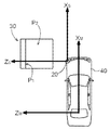
図1は、移動体としての車両40と車両40に搭載された距離画像センサ20との回転ずれを示す説明図である。図1において、XM軸及びZM軸は、車両40を基準とする三次元直交座標系における2つの座標軸を示している。図1において、紙面の裏面から表面に向かい、紙面に直交する方向がYM軸である。XS軸及びZS軸は、距離画像センサ20を基準とする三次元直交座標系における2つの座標軸である。図1において、紙面の裏面から表面に向かい、紙面に直交する方向がYS軸である。距離画像センサ20のZS軸は、画像センサにおける光学中心に相当する主軸である。尚、車両を基準とする座標系のZM軸は、一般的には180度反対方向の紙面右方向に定義される場合が多いが、本発明の説明を容易にするために、距離画像センサのZS軸と同方向としている。図中の符号Vは、距離画像センサ20の視野、即ち検出範囲である。
FIG. 1 is an explanatory diagram showing a rotational deviation between the
距離画像センサ20は、理想的には、XM軸とXS軸、YM軸とYS軸、ZM軸とZS軸とが平行となる状態で車両40に搭載される。しかし、機械的な公差を高精度に管理することは困難であり、現実には各軸が非平行となってずれが生じることになる。図1においては、距離画像センサ20の主軸ZSが、図示時計回りにθPずれたZ’Sとなる場合を例示している。図1では、平面の紙面に表現する関係上、XS−ZS平面上において、つまりYS軸を回転軸として回転しているように見えるが、実際には、全ての軸を回転軸として三次元的に回転する。
図1から明らかであるように、回転ずれに伴う検出位置のずれは、距離画像センサ20から離れるほど大きくなる。従って、距離画像データにより特定される座標値にも誤差が生じることとなる。距離画像センサ20が車両40に搭載される場合、運転支援や駐車支援に距離画像データが利用される。この際、当然ながら誤差が少ない方が好ましい。しかし、上述したように機械的な公差を高精度に管理することは現実的ではない。そこで、距離画像センサ20が車両40に搭載された状態において当該距離画像センサ20の姿勢、即ち座標系の回転に関する情報を取得して距離画像データが補正される。本実施形態では、このように座標系の回転に関する情報を取得することを、距離画像センサ20の校正と称する。校正に際しては、後述するように、所定の校正指標が利用される。
As apparent from FIG. 1, the displacement of the detection position due to the rotational displacement increases as the distance from the
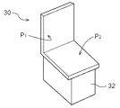
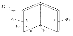
図2は、校正指標30の配置例を示す説明図である。図2に示すように、校正指標30は、第1平面P1と当該第1平面P1とは異なる第2平面P2とを有して構成される。校正指標30の構成は、後述するように図2に示す例に限定されないが、このように校正指標30を構成する工程は、校正指標構成工程である。距離画像センサ20の校正に際して、移動体としての車両40は、三次元基準座標系における所定位置において静止して配置される。この工程は、本発明の移動体設置工程に相当する。移動体としての車両は、輪留めなどを利用して比較的高い機械的公差の範囲内で、所定位置に設置される。三次元基準座標系は、種々の座標系を採用することが可能であるが、本実施形態においては、車両40を基準とする座標系(XM,YM,ZM)を三次元基準座標系とする。
FIG. 2 is an explanatory diagram illustrating an arrangement example of the
校正指標30は、静止状態にある車両40との位置情報、及び当該校正指標30の姿勢情報が三次元基準座標系において特定された状態で距離画像センサ20の検出範囲内Vに設置される。この工程は、本発明の校正指標設置工程に相当する。実際には、生産工場、整備工場などにおいて、校正指標30は固定的に設置されており、校正対象となる車両40が当該工場に入庫する。従って、実際には、車両40を静止させる位置に対して校正指標30の位置及び姿勢が特定され、車両40は、車両40を静止させる位置に対して高い精度で位置決めされる。これによって、車両40を基準とする三次元基準座標系(XM,YM,ZM)において、車両40及び校正指標30の位置及び姿勢が特定される。
The
ここで、車両40、校正指標30、距離画像センサ20のそれぞれを基準とする座標系の関係について、図3を利用して説明する。図3において、校正指標30の有する面の内の1つ、第1平面P1を基準とする座標系を(XT,YT,ZT)とする。第1平面P1は、三次元基準座標系である車両40基準の座標系(XM,YM,ZM)のXM−YM平面に平行に設置されている。第1平面P1を基準とする座標系(XT,YT,ZT)のZT軸と、三次元基準座標系(XM,YM,ZM)のZM軸とは、平行であり方向が逆である。
Here, the relationship between the coordinate systems based on the
上述したように、距離画像センサ20が理想的に車両40に設置された場合には、距離画像センサ20の座標系(XS,YS,ZS)は三次元基準座標系(XM,YM,ZM)と平行であり、方向も同一である。即ち、距離画像センサ20の座標系(XS,YS,ZS)は三次元基準座標系(XM,YM,ZM)が所定量、並進したものと考えることができる。従って、第1平面P1を基準とする座標系(XT,YT,ZT)のZT軸は、距離画像センサ20の座標系(XS,YS,ZS)のZS軸とも平行であり方向が逆である。
As described above, when the
しかし、上述したように、距離画像センサ20の座標系(XS,YS,ZS)は、三次元基準座標系(XM,YM,ZM)が所定量、並進したものと考えることはできず、並進成分及び回転成分の誤差を生じる。回転成分の誤差、つまり姿勢の誤差が距離画像データに与える影響は、並進成分の誤差、つまり位置の誤差が距離画像データに与える影響と比較して大きい。従って、ここでは、回転成分の誤差を校正する技術について説明する。
However, as described above, the coordinate system (X S , Y S , Z S ) of the
図4は、校正指標30と距離画像センサ20との間の回転を示す説明図である。校正指標30と車両40とは、回転成分の誤差なく設置されている条件とするので、校正指標30と距離画像センサ20との間の回転は、車両40と距離画像センサ20との間の回転と等価である。
FIG. 4 is an explanatory diagram showing the rotation between the
はじめに、図4において、距離画像センサ20が回転成分の誤差を有さない場合を考える。校正指標30の第1平面P1が三次元基準座標系のXM−YM平面に平行に設置されていることから、第1平面P1を基準とする座標系のZT軸は、距離画像センサ20の主軸である距離画像センサ20の座標系のZS軸とも平行であり方向が逆である。
First, consider a case in FIG. 4 where the
次に、距離画像センサ20がYS軸回りに回転し、主軸がZ’Sの方向を向いた場合には、主軸の方向であるZ’Sは、第1平面P1を基準とする座標系のZT軸とは平行ではなくなる。一方、主軸の回転を知らない距離画像センサ20からは、校正指標30の第1平面P1がYT軸回りに回転して、ZT軸がZ’Tの方向をむいているように観測される。
Next, the coordinate
上述したZS軸とZ’Sとの角度、及びZT軸とZ’Tとの角度は、距離画像センサ20及び校正指標30の何れの座標系においても同一のθPである。図4では、距離画像センサ20がYS軸回りに回転した、いわゆるパン角のずれを例として説明したが、XS軸回りの回転(チルト角)やZS軸回りの回転(ロール角)についても同様である。
The angle between the Z S axis and Z ′ S and the angle between the Z T axis and Z ′ T described above are the same θ P in both the coordinate systems of the
尚、本実施形態においては、距離画像センサ20の座標系(XS,YS,ZS)及び第1平面P1を基準とする座標系(XT,YT,ZT)の何れも、左手系を用いているが、互いにZ軸が相対している。従って、幾何学的に自明であるが、回転方向については、以下に示すように相違が生じることに留意する必要がある。
XT軸回りに右回転 : XS軸回りに左回転
YT軸回りに右回転 : YS軸回りに右回転
ZT軸回りに右回転 : ZS軸回りに左回転
In the present embodiment, both the coordinate system (X S , Y S , Z S ) of the
X T axis in clockwise rotation: X S axis in clockwise to counterclockwise rotation Y T axis: Y S axis in clockwise clockwise rotation Z T axis: left rotation to Z S axis
尚、図4に示した例において、校正指標30の第1平面P1の法線ベクトルZNの方向は、距離画像センサ20の主軸の方向Z’Sに対して相対的にθPだけ回転しているように見える。従って、校正指標30の第1平面P1の法線ベクトルによって、距離画像センサ20の回転を抽出することができる。
In the example shown in FIG. 4, the direction of the normal vector Z N of the first plane P 1 of the
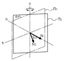
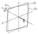
校正指標30の平面を特定して、当該平面の法線ベクトルを求めることにより、距離画像センサ20の回転を求めることが可能であるが、1つの平面からは2つの回転成分しか抽出することができない。この理由について、図5〜図7を利用して説明する。
図5は、平面Π1の垂直軸vを回転軸とする回転(パン角)を示しており、
図6は、平面Π1の水平軸hを回転軸とする回転(チルト角)を示しており、
図7は、平面Π1の法線nを回転軸とする回転(ロール角)を示している。
It is possible to determine the rotation of the
FIG. 5 shows rotation (pan angle) about the vertical axis v of the plane 1 1 as the rotation axis.
FIG. 6 shows rotation (tilt angle) about the horizontal axis h of the plane 1 as a rotation axis.
FIG. 7 shows the rotation (roll angle) about the normal line n of the plane 1 as the rotation axis.
図5に示すように、平面Π1が垂直軸vを回転軸として平面Π2へパン角θPだけ回転すると、その回転に応じて法線ベクトルN1もN2へとパン角θPだけ回転する。また、図6に示すように、平面Π1が水平軸hを回転軸として平面Π2へチルト角θTだけ回転すると、その回転に応じて法線ベクトルN1もN2へとチルト角θTだけ回転する。しかし、図7に示すように、平面Π1が法線N(n)を回転軸として平面Π2へロール角θRだけ回転しても、法線ベクトルNは変化しない。このように、1つの平面を観測するだけでは、三次元空間の全ての回転成分を抽出することはできない。 As shown in FIG. 5, when the plane 回 転1 is rotated by the pan angle θ P to the plane Π 2 with the vertical axis v as the rotation axis, the normal vector N 1 is also changed to N 2 by the pan angle θ P according to the rotation. Rotate. As shown in FIG. 6, when the plane 1 1 rotates about the horizontal axis h as the rotation axis to the plane Π 2 by the tilt angle θ T , the normal vector N 1 also changes to the tilt angle θ to N 2 according to the rotation. Rotate by T However, as shown in FIG. 7, also rotates the plane [pi 1 only roll angle theta R to the plane [pi 2 normals N (n) as a rotation axis, the normal vector N does not change. In this way, it is not possible to extract all rotation components in the three-dimensional space only by observing one plane.
そこで、本発明では、第1平面P1と当該第1平面P1とは異なる第2平面P2とを有して校正指標30が構成される。一方の平面では抽出できない回転成分は、当該一方の平面とは異なる他方の平面から抽出することが可能である。
Therefore, in the present invention, the
以下、このような校正指標を用いた具体的な校正装置の構成、及び校正方法の手順について、説明する。図8は、本発明の距離画像センサの校正装置の構成例を模式的に示すブロック図である。車両40は、距離画像センサ20、距離画像センサ20から距離画像データを受け取って画像処理を行う画像処理部50、距離画像データを補正する校正データが記憶された校正データ記憶部60とを備えている。画像処理部50は、距離画像データを用いて、車両40の周辺環境を認識する。例えば、画像処理部50は、駐車場に駐車された駐車車両を認識して駐車区画を認識する駐車支援装置を構成する1つの機能部として車両40に備えられる。校正データ記憶部60に記憶される校正データは、図8に示した形態では画像処理部50において用いられる。しかし、当然これに限定されることなく、距離画像センサ20において校正データが用いられ、校正済みの距離画像データが画像処理部50に送られる形態であってもよい。その他、校正部を設けて距離画像データを校正するようにしてもよい。
Hereinafter, a specific configuration of a calibration apparatus using such a calibration index and a procedure of a calibration method will be described. FIG. 8 is a block diagram schematically showing a configuration example of a calibration apparatus for a distance image sensor according to the present invention. The
校正データは、本発明の校正装置に相当する校正演算部10によって生成される。校正演算部10は車両40に搭載されていてもよいし、生産工場や整備工場など車両40の外に設置されていてもよい。校正演算部10が車両40に搭載される場合には、距離画像センサ20を制御するECU(electric control unit)や、画像処理部50を構成するマイクロコンピュータなどに内蔵されてもよい。また、校正演算部10が車両40の外に設置される場合には、距離画像センサ20から出力される距離画像データを受け取り、生成された校正データを出力するインターフェイスが、車両40と校正演算部10との間に設けられる。
The calibration data is generated by the
校正演算部10は、校正対象データを受け取るデータ受取部1と、平面を三次元基準座標系において特定する平面特定部3と、法線ベクトルを演算する法線ベクトル演算部4と、距離画像センサ20の回転量を演算する回転量演算部5とを備えて構成される。本実施形態では、校正演算部10は、さらに、校正対象データから、検出対象の平面に属する距離情報を抽出する距離情報抽出部2と、距離画像センサ20の回転量から校正データを生成する校正データ生成部6とを備えて構成される。
The
データ受取部1は、検出範囲V内に設置された校正指標30が含まれる距離画像データである校正対象データを受け取る機能部である。データ受取部1が校正対象データを受け取る際には、車両40は所定位置において静止状態にある。第1平面P1と第1平面P1とは異なる第2平面P2とを有して構成される校正指標30と車両40との位置情報は、三次元基準座標系(XM,YM,ZM)において特定された状態である。また、校正指標30の姿勢情報も、三次元基準座標系(XM,YM,ZM)において特定された状態である。データ受取部1が、距離画像データである校正対象データを受け取る工程は、本発明のデータ受取工程に相当する。
The
平面特定部3は、校正対象データに基づいて、第1平面P1及び第2平面P2のそれぞれの平面を三次元基準座標系(XM,YM,ZM)において特定する機能部である。はじめに、平面特定部3は、校正対象データの中からランダムに3つの画素データ(距離データ)を選択する。画素データはベクトル値であるから方位と距離値とを有する。従って、各点について、三次元基準座標系における座標値が得られる。次に、平面特定部3は、各点の座標値を下記(1)式で示す平面の方程式に代入し、3つの方程式を得る。
The
![]()
![]()
そして、平面特定部3は、3つの方程式からなる連立方程式を解き、A、B、C、Dの4つのパラメータを得て、平面P(P1、P2)の仮平面PTMPを決定する。次に、平面特定部3は、各画素データが仮平面PTMPに対してどの程度適合するかを判定し、適合する画素数をカウントする。ここで、適合の程度は、仮平面PTMPからのユークリッド距離が所定のしきい値以内であることなどを条件として判定される。平面特定部3は、順次、異なる3点をランダムに選択し、カウント値、即ち適合度が最大となる仮平面PTMPを平面Pとして特定する。平面特定部3が平面Pを特定するこの工程は、本発明の平面特定工程に相当する。
Then, the
距離画像センサ20の検出範囲Vは、校正指標30を充分に含む広い範囲である。従って、検出範囲Vの全ての範囲を対象として、上記のような平面を特定する演算を行うと演算時間を要する。そこで、距離情報抽出部2により、校正対象データから、第1平面P1と第2平面P2とに属する距離情報をそれぞれ抽出し、平面特定部3が、抽出された距離情報に基づいて平面P(P1、P2)を特定すると好適である。第1平面P1と第2平面P2とは、三次元基準座標系(XM,YM,ZM)における座標値が既知である。距離画像センサ20が回転成分の誤差を有していることから、第1平面P1と第2平面P2との座標値を距離画像データ(校正対象データ)において特定することはできない。しかし、ある程度の画素群を、それぞれ第1平面P1及び第2平面P2に関する属する距離情報として抽出することは可能である。このようにして、平面特定部3が、平面Pを適合させるためにサーチする画素群を、対象となる平面ごとに抽出することによって、演算負荷並びに演算時間を抑制することが可能となる。このような画素群の抽出は、平面特定工程に先立つ距離情報抽出工程において実行される。
The detection range V of the
尚、画素群の抽出は、上述したような座標値による集合のほか、以下に示す条件によって実施することも可能である。例えば、「奥行き方向(ベクトルの深さ)に差が少ない画素群」、「左右方向(パン方向)に差が少ない画素群」、「上下方向(チルト方向)に差が少ない画素群」などを条件とすることができる。どのような条件が適しているかについては、校正指標30の構造や配置によって異なるので、適宜選択すると好適である。尚、校正指標30の構造や配置についてのバリエーションの例については、図9〜図14を用いて後述する。
The extraction of the pixel group can be performed under the following conditions in addition to the set of coordinate values as described above. For example, "Pixel group with little difference in depth direction (vector depth)", "Pixel group with little difference in horizontal direction (pan direction)", "Pixel group with little difference in vertical direction (tilt direction)", etc. It can be a condition. Since what kind of conditions are suitable varies depending on the structure and arrangement of the
また、本実施形態の校正指標30のように、三次元基準座標系に対して第1平面P1及び第2平面P2の座標系が、平行や直交する場合、平面特定部3が仮平面PTMPの適合性を判定する際に、ユークリッド距離を演算する必要がなくなる。つまり、各軸に沿った距離がそのままユークリッド距離となるので、演算負荷が飛躍的に軽くなる。従って、校正指標30が有する平面の内の少なくとも1つが、三次元基準座標系における1つの軸に対して直交又は平行する状態で設置されると好適である。さらに、第1平面P1及び第2平面P2が、互いに直交する平面であると、両平面が、三次元基準座標系における1つの軸に対して直交又は平行する状態で設置されることとなり、好適である。
Also, as in the
平面特定部3により2つの平面P1及びP2が特定されると、法線ベクトル演算部4は、第1平面P1及び第2平面P2のそれぞれの三次元基準座標系における法線ベクトルを演算する。上記(1)式で示される平面の法線ベクトルは、平面を下記(2)式とおいて、次のように求められる。
When the two planes P 1 and P 2 are specified by the
![]()
![]()
(2)式の関数f(x,y,z)が0である点(x,y,z)における法線ベクトルは▽fである。従って、(3)式より、法線ベクトルは(4)式となる。 The normal vector at the point (x, y, z) where the function f (x, y, z) in the equation (2) is 0 is ff. Therefore, from equation (3), the normal vector becomes equation (4).

法線ベクトル演算部4は、このようにして、第1平面P1及び第2平面P2の法線ベクトルN1([A1,B1,C1]T)、N2([A2,B2,C2]T)を演算する。このようにして法線ベクトルを演算する工程は、本発明の法線ベクトル演算工程に相当する。
Normal
第1平面P1及び第2平面P2は、異なる平面であるので、一方の平面がその法線方向を回転軸として回転した場合でも、他方の法線ベクトルにより回転量を抽出することが可能である。回転量演算部5は、三次元基準座標系における校正指標30の姿勢情報と法線ベクトルN1及びN2とに基づいて、三次元基準座標系における距離画像センサ20の回転量を演算する。校正データ生成部6は、演算された回転量に基づいて、回転行列などの校正データを生成する。生成された校正データは、校正データ記憶部60に記憶される。距離画像センサ20の回転量を演算する工程は、本発明の回転量演算工程に相当する。そして、回転量に基づいて校正データを生成する校正データ生成工程は、回転量演算工程を経て実行される。
Since the first plane P 1 and the second plane P 2 are different planes, even when one plane rotates with its normal direction as the rotation axis, the rotation amount can be extracted by the other normal vector. It is. Rotation
上述したように、校正指標30の構造や配置は、上記実施形態に限定されるものではない。以下、校正指標30の構造や配置についてのバリエーションの例について、図9〜図14を用いて説明する。
As described above, the structure and arrangement of the
図9に示した校正指標30の配置は、第2平面P2を水平面とした場合の例である。図9に示す配置を採用する場合、校正指標30としては、図12及び図13に示すような形態のものが適用できる。図13は、第2平面P2を床面としている。このように、必ずしも校正指標30に2つの平面を形成することなく、適宜壁面や床面を利用して校正指標30を校正してもよい。図14は、第2平面P2を水平面とし、距離画像センサ20の検出範囲Vを考慮して、台32により校正指標30を上方へオフセットさせた例である。
Arrangement of the
図10は、平面Pを三次元基準座標系に直交及び平行させずに、校正指標30が配置される場合の例である。校正指標30には、図11に示すような形態のものが適用可能である。平面Pが三次元基準座標系に対して直交及び平行していなくても、設置位置と姿勢とが既知であれば、直交・平行からのずれ量をオフセット値として、各平面Pの法線ベクトルを演算することができる。
FIG. 10 shows an example in which the
また、上述したように、2つの平面は互いに直交していることが演算負荷上、好ましいが、異なる平面であれば、特に直交している必要はない。 In addition, as described above, the two planes are preferably orthogonal to each other in terms of calculation load. However, if they are different planes, they need not be orthogonal.
〔第2実施形態〕
上述したように、距離画像センサ20が有する取り付け誤差には、位置に関する誤差(並進誤差)と、姿勢に関する誤差(回転誤差)とが存在する。距離画像センサ20によって得られる画像に対しては、回転誤差による影響の方が大きいため、上記第1実施形態では、回転誤差を校正する技術について詳述した。しかし、当然ながら距離画像センサ20が車両40に搭載された状態において当該距離画像センサ20の姿勢及び位置、即ち座標系の回転及び並進に関する情報を取得して距離画像データが補正されることが好ましい。そこで、第2実施形態では回転誤差に加えて、並進誤差を校正する技術について説明する。第2実施形態では、座標系の回転及び並進に関する情報を取得することを、距離画像センサ20の校正と称する。以下、並進誤差の校正について詳述し、回転誤差の校正については、上述した通りであるので、適宜説明を省略する。
[Second Embodiment]
As described above, the attachment error of the
並進移動は、図2に示す座標系の相関図において、三次元基準座標(XM,YM,ZM)の原点OMと、距離画像センサ20の座標系(XS,YS,ZS)の原点OSとの関係により規定される。対応する点は、原点同士に限定されるわけではなく、任意の点を対応させることが可能である。例えば、校正指標30の所定の1点の座標は、既知であるから、この既知の点が距離画像センサ20の画素データとしてどのようなベクトル値を有するのかがわかれば、対応関係が明らかとなる。ただし、距離画像センサ20の解像度は高くはない場合がある。このような場合には、距離画像データ上において直接、対象画素(座標)を特定すると誤差が大きくなる。
Translational movement, in the correlation diagram of the coordinate system shown in FIG. 2, three-dimensional reference coordinate (X M, Y M, Z M) and the origin O M of the distance coordinate system of the image sensor 20 (X S, Y S, Z It is defined by the relationship between the origin O S of S). Corresponding points are not limited to the origins, and arbitrary points can be associated. For example, since the coordinates of one predetermined point of the
第1実施形態で用いた校正指標30を用いて、並進誤差を特定するための対象点PIを特定する原理について、図15を利用して説明する。校正指標30は、第1平面P1と第2平面P2とが交差する交差部LIを有する。また、校正指標30は、少なくとも第1平面P1及び第2平面P2の内の一方の平面端部LE1又はLE2と、交差部PIとが交差する交点PIを有して構成されている。この交点PIは、三次元基準座標系において既知とすることができるから、距離画像データに基づいて交点PIが特定できれば、並進誤差を演算することが可能となる。
The principle of specifying the target point PI for specifying the translation error using the
第1実施形態において説明したように第1平面P1と第2平面P2とは特定可能であるから、第1平面P1と第2平面P2との交線、即ち交差部LIは特定可能である。また、校正指標30の全てが距離画像センサ20の検出範囲Vに含まれていれば、平面端部LE1やLE2は、距離画像データ上においてエッジとなる。従って、平面端部LE1やLE2は、ガウシアンフィルタなどの公知のエッジ検出手法により、特定可能である。そして、平面端部LE1、LE2の少なくとも一方と、交差部LIとが特定されれば、交点PIも特定可能である。
As described in the first embodiment, since the first plane P 1 and the second plane P 2 can be specified, the intersection line of the first plane P 1 and the second plane P 2 , that is, the intersection LI is specified. Is possible. Further, if all of the
尚、このようなエッジ検出の演算を伴う場合、平面端部LE1又はLE2のコントラストが高いことが好ましい。校正指標30は、第1実施形態の場合においても、面を正確に特定する上で、壁面などから一定の距離だけ離して設置されることが好ましい。第2実施形態においては、さらに校正指標30と他のものとが混同されないように、校正指標30が配置されることが好ましい。
In addition, when such an edge detection calculation is involved, it is preferable that the contrast of the planar end portion LE 1 or LE 2 is high. Even in the case of the first embodiment, the
図16は、回転及び並進を校正可能な距離画像センサの校正装置の構成例を模式的に示すブロック図である。図8に示した第1実施形態のブロックに対して、校正演算部10に、交点座標演算部7と並進演算部8とが加えられている点が相違する。後述するように、平面特定部3、校正データ生成部6以外の各機能部については、第1実施形態と同様であるから、説明を省略する。
FIG. 16 is a block diagram schematically illustrating a configuration example of a calibration apparatus for a distance image sensor capable of calibrating rotation and translation. 8 is different from the block of the first embodiment shown in FIG. 8 in that an intersection coordinate
尚、第2実施形態においては、距離情報抽出部2において、校正対象データから、第1平面P1と第2平面P2とに属する距離情報をそれぞれ抽出する場合に、範囲を絞り込まない方が好ましい。平面を特定する上では、平面端部LE1、LE2の近傍の画素データがなくても問題は少なく、逆に、画素データが乱れる可能性がある平面端部LE1、LE2の近傍の画素データを用いない方が好ましい場合がある。しかし、本第2実施形態では、平面端部LE1、LE2を特定する必要があるため、距離情報抽出部2において平面を特定する範囲を絞り込まない方が好ましい。
In the second embodiment, when the distance
平面特定部3は、第1実施形態において説明した機能に加え、さらに、交差部PLと交差する平面端部LE1、LE2を特定する。即ち、平面特定部3は、公知のエッジ検出手法などを用いて、平面端部LE1、LE2を特定する(平面特定工程)。
In addition to the functions described in the first embodiment, the
平面特定工程の後、交点座標特定工程が実施される。交点座標演算部7は、平面特定部3で特定された第1平面P1及び第2平面P2及び平面端部LE1、LE2の三次元基準座標系における交点PIの座標を演算する機能部である。具体的には、第1平面P1及び第2平面P2に基づいて、交差部PLを特定し、交差部PLと平面端部LE1、LE2との交点PIの座標を演算する。
After the plane specifying step, an intersection coordinate specifying step is performed. The intersection coordinate
交点座標特定工程の後、並進量演算工程が実施される。並進量演算部8は、三次元基準座標系における校正指標30の位置情報と交点PIの座標とに基づいて、三次元基準座標系における距離画像センサの並進量を演算する機能部である。
After the intersection point coordinate specifying step, a translation amount calculating step is performed. The translation amount calculation unit 8 is a functional unit that calculates the translation amount of the distance image sensor in the three-dimensional reference coordinate system based on the position information of the
並進量演算工程と平行して、あるいは時分割処理により実行される回転量演算工程及び並進量演算工程の後、校正データ生成工程が実施される。校正データ生成部6は、回転量演算部5で求めた回転量と、並進量演算部8で求めた並進量とを用いて、校正データを生成する。生成された校正データは、校正データ記憶部60に記憶される。
In parallel with the translation amount calculation step or after the rotation amount calculation step and the translation amount calculation step executed by the time-sharing process, a calibration data generation step is performed. The calibration
〔第3実施形態〕
第2実施形態においては、第1平面P1及び第2平面P2の内の一方の平面端部LE1又はLE2をエッジ検出手法などによって検出することによって交点PIを特定した。しかし、距離画像センサ30の解像度や、校正指標30が設置される環境によっては、エッジ検出の誤差が多くなる場合がある。そこで、第3実施形態においては、より確実に並進誤差を校正できる実施形態について説明する。
[Third Embodiment]
In the second embodiment, it was identified intersection PI by the flat end LE 1 or LE 2 of one of the first plane P 1 and a second plane P 2 is detected by an edge detection technique. However, the edge detection error may increase depending on the resolution of the
図17は、第3実施形態において使用される校正指標30の一例を示す斜視図である。図17に示すように、この校正指標30は、第1実施形態の校正指標30に対し、さらに第1平面P1及び第2平面P2とは異なる第3平面P3を有すると共に、これら3つの平面が交差する交点PIを有して構成される。
FIG. 17 is a perspective view showing an example of the
第3実施形態に係る校正演算部10は、図16に示し、第2実施形態において説明したものと同じである。データ受取部1の機能については、第1実施形態及び第2実施形態と同様である。距離情報抽出部2は、第1平面P1及び第2平面P2に加えて、第3平面P3に属する距離データを抽出する点で第1実施形態及び第2実施形態と相違するが、その他の点については同様の機能である。平面特定部3は、第1平面P1及び第2平面P2に加えて、さらに第3平面P3を三次元基準座標系において特定する。平面の特定方法については、第1実施形態で説明したものと同様である。法線ベクトル演算部4は、3つの平面の内、少なくとも2つの平面の法線ベクトルを演算する。回転量演算部5は、少なくとも2つの法線ベクトルに基づいて、回転量を演算する(回転量演算工程)。
The
交点座標演算部7は、平面特定部で特定された第1平面P1、第2平面P2及び第3平面P3の三次元基準座標系における交点PIの座標を演算する。この工程は、本発明の交点座標演算工程に相当する。並進量演算部8は、三次元基準座標系における校正指標30位置情報と交点PIの座標とに基づいて、三次元基準座標系における距離画像センサ20の並進量を演算する。この工程は、本発明の並進量演算工程に相当する。
The intersection coordinate
回転量演算工程及び並進量演算工程の後、校正データ生成工程が実施される。校正データ生成部6は、回転量演算部5で求めた回転量と、並進量演算部8で求めた並進量とを用いて、校正データを生成する。生成された校正データは、校正データ記憶部60に記憶される。
After the rotation amount calculation step and the translation amount calculation step, a calibration data generation step is performed. The calibration
このように、第3平面P3を有する校正指標30を用いることにより、回転量と並進量とをほぼ同じ処理によって演算することができる。尚、校正指標30は、図17に例示した構成に限定されず、図18に示すように構成することも可能である。図18に示した構成指標30は、第3平面P3を床面で代用したものである。このような校正指標30を用いる場合には、第1実施形態で使用した校正指標30を転用することも可能である。校正演算部10がマイクロコンピュータなどによって構成される場合、校正指標30などのハードウェアを変更することなく、回転誤差に加えて並進誤差を校正することが可能な校正装置へアップグレードすることが可能である。
Thus, by using the
尚、第1実施形態における説明で明らかであるが、図17及び図18に例示したように、第1平面P1、第2平面P2及び第3平面P3は互いに直交すると好適である。また、校正指標30が有する平面の内の少なくとも1つが、三次元基準座標系における1つの軸に対して直交又は平行する状態で設置されると好適である。3面の全てが、三次元基準座標系における軸に対して直交又は平行する状態で設置されるとさらに好適である。しかし、第3実施形態においても、第1実施形態と同様に、校正指標30が互いに異なる平面を有して構成されていれば、演算負荷が増加したとしても校正機能そのものの性能に関して問題はない。また、第1実施形態において図9〜図14を用いて例示したように、第3実施形態においても、校正指標30が種々の形態及び姿勢を取り得ることは明らかである。
As is apparent from the description of the first embodiment, as illustrated in FIGS. 17 and 18, it is preferable that the first plane P 1 , the second plane P 2, and the third plane P 3 are orthogonal to each other. In addition, it is preferable that at least one of the planes of the
〔第4実施形態〕
上記、各実施形態においては、主としてアクティブ型の距離画像センサにおいて好適な校正装置及び校正方法について説明した。距離画像センサには、CCDやCISなどにより取得された濃淡画像をステレオ画像処理することによって距離情報を取得して距離画像を生成するようなパッシブ型の構成のものも存在する。このような濃淡画像を用いる距離画像センサの場合には、校正指標の特徴点の検出が容易となるように、校正指標に模様を描いておくと好適である。
[Fourth Embodiment]
In each of the above embodiments, a calibration apparatus and a calibration method suitable mainly for an active distance image sensor have been described. Some distance image sensors have a passive configuration in which distance information is generated by performing stereo image processing on a grayscale image acquired by a CCD or CIS to generate a distance image. In the case of a distance image sensor using such a grayscale image, it is preferable to draw a pattern on the calibration index so that the feature points of the calibration index can be easily detected.
以上説明したように、本発明によって、簡単なシステム構成により、移動体に取り付けられた距離画像センサを、当該移動体に取り付けられた状態で校正することのできる校正装置及び校正方法を提供することが可能となる。 As described above, according to the present invention, there is provided a calibration apparatus and a calibration method capable of calibrating a distance image sensor attached to a moving body with a simple system configuration while attached to the moving body. Is possible.
1:データ受取部
2:距離情報抽出部
3:平面特定部
4:法線ベクトル演算部
5:回転量演算部
7:交点座標演算部
8:並進量演算部
10:校正演算部(校正装置)
20:距離画像センサ
30:校正指標
40:移動体
LE1、LE2:平面端部
P1:第1平面
P2:第2平面
P3:第3平面
PI:交点
PL:交差部
V:検出範囲
1: data receiving unit 2: distance information extracting unit 3: plane specifying unit 4: normal vector calculating unit 5: rotation amount calculating unit 7: intersection coordinate calculating unit 8: translation amount calculating unit 10: calibration calculating unit (calibration device)
20: Distance image sensor 30: Calibration index 40: Moving object LE 1 , LE 2 : Plane end P 1 : First plane P 2 : Second plane P 3 : Third plane PI: Intersection PL: Intersection V: Detection range
Claims (10)
第1平面と当該第1平面とは異なる第2平面とを有して構成される校正指標の位置情報、所定位置において静止状態にある前記移動体の位置情報、及び当該校正指標の姿勢情報が三次元基準座標系において既知の状態であり、
前記検出範囲内に設置された当該校正指標が含まれる距離画像データである校正対象データを前記距離画像センサから受け取るデータ受取部と、
前記校正対象データに基づいて、前記第1平面及び前記第2平面のそれぞれの平面を前記三次元基準座標系において特定する平面特定部と、
特定された前記第1平面及び前記第2平面のそれぞれの前記三次元基準座標系における法線ベクトルを演算する法線ベクトル演算部と、
前記三次元基準座標系における前記姿勢情報と前記法線ベクトルとに基づいて、前記三次元基準座標系における前記距離画像センサの回転量を演算する回転量演算部と、を備える距離画像センサの校正装置。 Calibration of a distance image sensor that is attached to a moving body, detects a distance for each direction in a detection range, and calibrates the distance image sensor that generates distance image data from the detected distance information while attached to the moving body. A device,
Position information of a calibration index configured to include a first plane and a second plane different from the first plane, position information of the moving object that is stationary at a predetermined position, and posture information of the calibration index It is a known state in the 3D reference coordinate system,
A data receiving unit that receives from the distance image sensor calibration target data that is distance image data including the calibration index set in the detection range;
A plane identifying unit that identifies each of the first plane and the second plane in the three-dimensional reference coordinate system based on the calibration target data;
A normal vector calculator that calculates a normal vector in the three-dimensional reference coordinate system of each of the identified first plane and second plane;
A distance image sensor calibration comprising: a rotation amount calculation unit that calculates a rotation amount of the distance image sensor in the three-dimensional reference coordinate system based on the posture information and the normal vector in the three-dimensional reference coordinate system. apparatus.
前記平面特定部は、抽出された前記距離情報を用いて平面を特定する請求項1に記載の距離画像センサの校正装置。 Distances for extracting the distance information belonging to the first plane and the second plane from the calibration target data based on the position information of the calibration index, the position information of the moving body, and the posture information of the calibration index, respectively. An information extraction unit;
The range image sensor calibration device according to claim 1, wherein the plane specifying unit specifies a plane using the extracted distance information.
前記平面特定部は、さらに、前記交差部と交差する前記平面端部を特定するものであり、さらに、
前記平面特定部で特定された前記第1平面及び前記第2平面及び前記平面端部の前記三次元基準座標系における交点座標を演算する交点座標演算部と、
前記三次元基準座標系における前記位置情報と前記交点座標とに基づいて、前記三次元基準座標系における前記距離画像センサの並進量を演算する並進量演算部と、を備える請求項1に記載の距離画像センサの校正装置。 The calibration index has an intersection where the first plane and the second plane intersect, and at least one plane end of the first plane and the second plane intersects the intersection. Having an intersection at a known position in the three-dimensional reference coordinate system,
The plane specifying portion further specifies the plane end portion that intersects the intersecting portion, and
An intersection coordinate calculation unit that calculates an intersection coordinate in the three-dimensional reference coordinate system of the first plane, the second plane, and the end of the plane specified by the plane specifying unit;
The translation amount calculation unit that calculates a translation amount of the distance image sensor in the three-dimensional reference coordinate system based on the position information and the intersection coordinates in the three-dimensional reference coordinate system. Distance image sensor calibration device.
前記平面特定部は、さらに前記第3平面を前記三次元基準座標系において特定するものであり、さらに、
前記平面特定部で特定された前記第1平面、前記第2平面及び前記第3平面の前記三次元基準座標系における交点座標を演算する交点座標演算部と、
前記三次元基準座標系における前記位置情報と前記交点座標とに基づいて、前記三次元基準座標系における前記距離画像センサの並進量を演算する並進量演算部と、を備える請求項1又は2に記載の距離画像センサの校正装置。 The calibration index further includes a third plane different from the first plane and the second plane, and has an intersection where these three planes intersect.
The plane specifying unit further specifies the third plane in the three-dimensional reference coordinate system, and
An intersection coordinate calculation unit that calculates an intersection coordinate in the three-dimensional reference coordinate system of the first plane, the second plane, and the third plane specified by the plane specifying unit;
A translation amount calculation unit that calculates a translation amount of the distance image sensor in the three-dimensional reference coordinate system based on the position information and the intersection coordinates in the three-dimensional reference coordinate system. The distance image sensor calibration apparatus described.
前記平面特定部は、抽出された前記距離情報を用いて平面を特定する請求項4に記載の距離画像センサの校正装置。 A distance information extraction unit for extracting distance information belonging to the first plane and the second plane from the calibration target data, respectively, further extracts distance information belonging to the third plane,
The distance image sensor calibration apparatus according to claim 4, wherein the plane specifying unit specifies a plane using the extracted distance information.
前記移動体を三次元基準座標系における所定位置において静止させる移動体設置工程と、
第1平面と当該第1平面とは異なる第2平面とを有して構成される校正指標を、静止状態にある前記移動体との位置情報、及び当該校正指標の姿勢情報が三次元基準座標系において特定された状態で前記検出範囲内に設置する校正指標設置工程と、
前記移動体が前記所定位置に静止する状態で前記距離画像センサにより生成され、前記校正指標が含まれる距離画像データである校正対象データを前記距離画像センサから受け取るデータ受取工程と、
前記校正対象データに基づいて、前記第1平面及び前記第2平面のそれぞれの平面を前記三次元基準座標系において特定する平面特定工程と、
特定された前記第1平面及び前記第2平面のそれぞれの前記三次元基準座標系における法線ベクトルを演算する法線ベクトル演算工程と、
前記三次元基準座標系における前記姿勢情報と前記法線ベクトルとに基づいて、前記三次元基準座標系における前記距離画像センサの回転量を演算する回転量演算工程と、を備える距離画像センサの校正方法。 Calibration of a distance image sensor that is attached to a moving body, detects a distance for each direction in a detection range, and calibrates the distance image sensor that generates distance image data from the detected distance information while attached to the moving body. A method,
A moving body installation step for stopping the moving body at a predetermined position in a three-dimensional reference coordinate system;
A calibration index configured to include a first plane and a second plane different from the first plane, position information on the moving object in a stationary state, and posture information of the calibration index are three-dimensional reference coordinates. A calibration index setting step for setting within the detection range in a state specified in the system;
A data receiving step of receiving from the distance image sensor calibration target data that is generated by the distance image sensor in a state where the moving body is stationary at the predetermined position and includes the calibration index;
A plane identifying step for identifying each of the first plane and the second plane in the three-dimensional reference coordinate system based on the calibration object data;
A normal vector calculation step of calculating a normal vector in the three-dimensional reference coordinate system of each of the identified first plane and second plane;
A rotation amount calculation step of calculating a rotation amount of the distance image sensor in the three-dimensional reference coordinate system based on the posture information and the normal vector in the three-dimensional reference coordinate system; Method.
前記平面特定工程は、さらに前記第3平面を前記三次元基準座標系において特定するものであり、さらに、
前記平面特定部で特定された前記第1平面、前記第2平面及び前記第3平面の前記三次元基準座標系における交点座標を演算する交点座標演算工程と、
前記三次元基準座標系における前記位置情報と前記交点座標とに基づいて、前記三次元基準座標系における前記距離画像センサの並進量を演算する並進量演算工程と、を備える請求項9に記載の距離画像センサの校正方法。
The calibration index further has a third plane different from the first plane and the second plane,
The plane specifying step further specifies the third plane in the three-dimensional reference coordinate system, and
An intersection coordinate calculation step of calculating an intersection coordinate in the three-dimensional reference coordinate system of the first plane, the second plane, and the third plane specified by the plane specifying unit;
The translation amount calculation step of calculating a translation amount of the distance image sensor in the three-dimensional reference coordinate system based on the position information in the three-dimensional reference coordinate system and the intersection coordinates. Distance image sensor calibration method.
Priority Applications (3)
| Application Number | Priority Date | Filing Date | Title |
|---|---|---|---|
| JP2008048548A JP5278728B2 (en) | 2008-02-28 | 2008-02-28 | Distance image sensor calibration apparatus and calibration method |
| EP09002217.9A EP2096460B1 (en) | 2008-02-28 | 2009-02-17 | Calibration device and calibration method for range image sensor |
| US12/389,025 US7822571B2 (en) | 2008-02-28 | 2009-02-19 | Calibration device and calibration method for range image sensor |
Applications Claiming Priority (1)
| Application Number | Priority Date | Filing Date | Title |
|---|---|---|---|
| JP2008048548A JP5278728B2 (en) | 2008-02-28 | 2008-02-28 | Distance image sensor calibration apparatus and calibration method |
Publications (2)
| Publication Number | Publication Date |
|---|---|
| JP2009204532A true JP2009204532A (en) | 2009-09-10 |
| JP5278728B2 JP5278728B2 (en) | 2013-09-04 |
Family
ID=40674099
Family Applications (1)
| Application Number | Title | Priority Date | Filing Date |
|---|---|---|---|
| JP2008048548A Expired - Fee Related JP5278728B2 (en) | 2008-02-28 | 2008-02-28 | Distance image sensor calibration apparatus and calibration method |
Country Status (3)
| Country | Link |
|---|---|
| US (1) | US7822571B2 (en) |
| EP (1) | EP2096460B1 (en) |
| JP (1) | JP5278728B2 (en) |
Cited By (11)
| Publication number | Priority date | Publication date | Assignee | Title |
|---|---|---|---|---|
| JP2014173922A (en) * | 2013-03-07 | 2014-09-22 | Omron Corp | Imaging apparatus, rotation angle estimation method, and rotation angle estimation program |
| JP2016029350A (en) * | 2014-07-25 | 2016-03-03 | 株式会社デンソー | Sensor attachment angle detector and sensor attachment angle detection program |
| JP2017026551A (en) * | 2015-07-27 | 2017-02-02 | 日産自動車株式会社 | Calibration target and calibration method |
| JP2018185203A (en) * | 2017-04-25 | 2018-11-22 | トヨタ自動車株式会社 | Mobile robot |
| WO2019082460A1 (en) * | 2017-10-23 | 2019-05-02 | ソニー株式会社 | Information processing device, information processing method, and program |
| JP2019132700A (en) * | 2018-01-31 | 2019-08-08 | シナノケンシ株式会社 | Marker and measurement method |
| WO2020045057A1 (en) * | 2018-08-31 | 2020-03-05 | パイオニア株式会社 | Posture estimation device, control method, program, and storage medium |
| JP2020032986A (en) * | 2018-08-31 | 2020-03-05 | パイオニア株式会社 | Posture estimation device, control method, program and storage medium |
| JP2021009634A (en) * | 2019-07-03 | 2021-01-28 | 株式会社ダイヘン | Mobile body |
| CN112654841A (en) * | 2018-07-06 | 2021-04-13 | 云海智行股份有限公司 | System, method and apparatus for calibrating a sensor mounted on a device |
| CN113847874A (en) * | 2021-08-20 | 2021-12-28 | 天津大学 | Vision-based displacement direction calibration method for displacement table |
Families Citing this family (30)
| Publication number | Priority date | Publication date | Assignee | Title |
|---|---|---|---|---|
| US7379769B2 (en) | 2003-09-30 | 2008-05-27 | Sunnybrook Health Sciences Center | Hybrid imaging method to monitor medical device delivery and patient support for use in the method |
| US7940047B2 (en) | 2007-11-23 | 2011-05-10 | Sentinelle Medical, Inc. | Microcontroller system for identifying RF coils in the bore of a magnetic resonance imaging system |
| DE102008042018A1 (en) * | 2008-09-12 | 2010-03-18 | Robert Bosch Gmbh | Method for adjusting or calibrating a vehicle surroundings sensor and vehicle surroundings sensor adjustment or calibration arrangement |
| EP2445413B1 (en) | 2009-06-23 | 2020-02-12 | Invivo Corporation | Variable angle guide holder for a biopsy guide plug |
| EP2503934B1 (en) | 2009-11-27 | 2021-10-20 | Hologic, Inc. | Systems and methods for tracking positions between imaging modalities and transforming a displayed three-dimensional image corresponding to a position and orientation of a probe |
| JP5163713B2 (en) * | 2010-08-24 | 2013-03-13 | カシオ計算機株式会社 | Distance image sensor, distance image generation device, distance image data acquisition method, and distance image generation method |
| US9332926B2 (en) | 2010-11-25 | 2016-05-10 | Invivo Corporation | MRI imaging probe |
| US20120173185A1 (en) * | 2010-12-30 | 2012-07-05 | Caterpillar Inc. | Systems and methods for evaluating range sensor calibration data |
| JP5632762B2 (en) * | 2011-01-25 | 2014-11-26 | パナソニック株式会社 | POSITIONING INFORMATION FORMING DEVICE, DETECTING DEVICE, AND POSITIONING INFORMATION FORMING METHOD |
| WO2013049597A1 (en) * | 2011-09-29 | 2013-04-04 | Allpoint Systems, Llc | Method and system for three dimensional mapping of an environment |
| DE102011084264A1 (en) * | 2011-10-11 | 2013-04-11 | Robert Bosch Gmbh | Method and device for calibrating an environmental sensor |
| ES2961685T3 (en) | 2013-03-15 | 2024-03-13 | Hologic Inc | System and method of review and analysis of cytological samples |
| CN103743410A (en) * | 2013-12-20 | 2014-04-23 | 河北汉光重工有限责任公司 | Beyond visual range target location precision analysis method based on Monte Carlo |
| US9384662B2 (en) | 2014-04-17 | 2016-07-05 | Ford Global Technologies, Llc | Parking assistance for a vehicle |
| KR101755813B1 (en) * | 2015-07-20 | 2017-07-19 | 현대자동차주식회사 | System for Parking Steering Assist System and method for Correcting Parking Guide Line thereof |
| US10757394B1 (en) | 2015-11-09 | 2020-08-25 | Cognex Corporation | System and method for calibrating a plurality of 3D sensors with respect to a motion conveyance |
| US11562502B2 (en) | 2015-11-09 | 2023-01-24 | Cognex Corporation | System and method for calibrating a plurality of 3D sensors with respect to a motion conveyance |
| US10812778B1 (en) | 2015-11-09 | 2020-10-20 | Cognex Corporation | System and method for calibrating one or more 3D sensors mounted on a moving manipulator |
| CN105675014B (en) * | 2016-01-07 | 2018-08-10 | 北京电子工程总体研究所 | A kind of compound detection system benchmark axis deviation scaling method and calibration system |
| CN115686005A (en) * | 2016-06-28 | 2023-02-03 | 柯尼亚塔有限公司 | System and computer-implemented method for training virtual models of an autopilot system |
| CN111033316B (en) * | 2017-08-18 | 2024-04-23 | 株式会社小糸制作所 | Identification sensor, control method therefor, automobile, vehicle lamp, object identification system, and object identification method |
| DE102018205065A1 (en) | 2018-04-04 | 2019-10-10 | Volkswagen Aktiengesellschaft | Method for calibrating a position sensor in a vehicle, computer program, storage means, control unit and calibration path |
| CN110633336B (en) * | 2018-06-05 | 2022-08-05 | 杭州海康机器人技术有限公司 | Method and device for determining laser data search range and storage medium |
| JP6717887B2 (en) * | 2018-07-12 | 2020-07-08 | ファナック株式会社 | Distance measuring device having distance correction function |
| CN110221313B (en) * | 2019-06-18 | 2021-04-16 | 广东嘉腾机器人自动化有限公司 | Laser radar installation position correction method of AGV (automatic guided vehicle) and AGV |
| CN110455277B (en) * | 2019-08-19 | 2023-04-07 | 哈尔滨工业大学 | High-precision attitude measurement device and method based on data fusion of Internet of things |
| DE102019129600B4 (en) * | 2019-11-04 | 2023-11-02 | Evitado Technologies GmbH | Portable sensor system |
| US10814799B1 (en) * | 2019-11-25 | 2020-10-27 | GM Global Technology Operations LLC | Mitigation of errant signal effects on an image sensor of a vehicle |
| CN113188570A (en) * | 2021-04-27 | 2021-07-30 | 西南石油大学 | Attitude error calibration method of inclinometer while drilling based on support vector classifier and K-proximity method |
| US20230089832A1 (en) * | 2021-09-22 | 2023-03-23 | Motional Ad Llc | Calibration courses and targets |
Citations (3)
| Publication number | Priority date | Publication date | Assignee | Title |
|---|---|---|---|---|
| JP2002202122A (en) * | 2001-01-05 | 2002-07-19 | Olympus Optical Co Ltd | Calibration method for two-dimensional distance image sensor |
| JP2006038843A (en) * | 2004-07-08 | 2006-02-09 | Ibeo Automobile Sensor Gmbh | Method for calibrating distance image sensor |
| JP2007256091A (en) * | 2006-03-23 | 2007-10-04 | Space Vision:Kk | Method and apparatus for calibrating range finder |
Family Cites Families (7)
| Publication number | Priority date | Publication date | Assignee | Title |
|---|---|---|---|---|
| JPH08313212A (en) | 1995-05-17 | 1996-11-29 | Yaskawa Electric Corp | Integrating method of depth map |
| JP3453734B2 (en) | 1996-08-07 | 2003-10-06 | 株式会社小松製作所 | Calibration method |
| GB2336057B (en) * | 1998-04-02 | 2002-05-08 | Discreet Logic Inc | Producing image data in a virtual set |
| JP2002046087A (en) | 2000-08-01 | 2002-02-12 | Mitsubishi Heavy Ind Ltd | Three-dimensional position measuring method and apparatus, and robot controller |
| JP2003259357A (en) | 2002-03-05 | 2003-09-12 | Mitsubishi Electric Corp | Calibration method for camera and attachment of camera |
| JP2006252473A (en) | 2005-03-14 | 2006-09-21 | Toshiba Corp | Obstacle detector, calibration device, calibration method and calibration program |
| JP4501003B2 (en) | 2005-07-15 | 2010-07-14 | 国立大学法人静岡大学 | Face posture detection system |
-
2008
- 2008-02-28 JP JP2008048548A patent/JP5278728B2/en not_active Expired - Fee Related
-
2009
- 2009-02-17 EP EP09002217.9A patent/EP2096460B1/en not_active Not-in-force
- 2009-02-19 US US12/389,025 patent/US7822571B2/en not_active Expired - Fee Related
Patent Citations (3)
| Publication number | Priority date | Publication date | Assignee | Title |
|---|---|---|---|---|
| JP2002202122A (en) * | 2001-01-05 | 2002-07-19 | Olympus Optical Co Ltd | Calibration method for two-dimensional distance image sensor |
| JP2006038843A (en) * | 2004-07-08 | 2006-02-09 | Ibeo Automobile Sensor Gmbh | Method for calibrating distance image sensor |
| JP2007256091A (en) * | 2006-03-23 | 2007-10-04 | Space Vision:Kk | Method and apparatus for calibrating range finder |
Cited By (14)
| Publication number | Priority date | Publication date | Assignee | Title |
|---|---|---|---|---|
| JP2014173922A (en) * | 2013-03-07 | 2014-09-22 | Omron Corp | Imaging apparatus, rotation angle estimation method, and rotation angle estimation program |
| JP2016029350A (en) * | 2014-07-25 | 2016-03-03 | 株式会社デンソー | Sensor attachment angle detector and sensor attachment angle detection program |
| JP2017026551A (en) * | 2015-07-27 | 2017-02-02 | 日産自動車株式会社 | Calibration target and calibration method |
| JP2018185203A (en) * | 2017-04-25 | 2018-11-22 | トヨタ自動車株式会社 | Mobile robot |
| WO2019082460A1 (en) * | 2017-10-23 | 2019-05-02 | ソニー株式会社 | Information processing device, information processing method, and program |
| US11240484B2 (en) | 2017-10-23 | 2022-02-01 | Sony Corporation | Information processing apparatus and information processing method for stereo imaging based on corrected parameters |
| CN111183331A (en) * | 2017-10-23 | 2020-05-19 | 索尼公司 | Information processing apparatus, information processing method, and program |
| JP2019132700A (en) * | 2018-01-31 | 2019-08-08 | シナノケンシ株式会社 | Marker and measurement method |
| CN112654841A (en) * | 2018-07-06 | 2021-04-13 | 云海智行股份有限公司 | System, method and apparatus for calibrating a sensor mounted on a device |
| WO2020045057A1 (en) * | 2018-08-31 | 2020-03-05 | パイオニア株式会社 | Posture estimation device, control method, program, and storage medium |
| JP2020032986A (en) * | 2018-08-31 | 2020-03-05 | パイオニア株式会社 | Posture estimation device, control method, program and storage medium |
| JP2021009634A (en) * | 2019-07-03 | 2021-01-28 | 株式会社ダイヘン | Mobile body |
| JP7284011B2 (en) | 2019-07-03 | 2023-05-30 | 株式会社ダイヘン | moving body |
| CN113847874A (en) * | 2021-08-20 | 2021-12-28 | 天津大学 | Vision-based displacement direction calibration method for displacement table |
Also Published As
| Publication number | Publication date |
|---|---|
| EP2096460A2 (en) | 2009-09-02 |
| US7822571B2 (en) | 2010-10-26 |
| JP5278728B2 (en) | 2013-09-04 |
| EP2096460B1 (en) | 2014-12-24 |
| US20090222229A1 (en) | 2009-09-03 |
| EP2096460A3 (en) | 2011-06-22 |
Similar Documents
| Publication | Publication Date | Title |
|---|---|---|
| JP5278728B2 (en) | Distance image sensor calibration apparatus and calibration method | |
| JP7161410B2 (en) | System and method for identifying camera pose in scene | |
| JP4636346B2 (en) | Car camera calibration apparatus, method, and program | |
| US9361687B2 (en) | Apparatus and method for detecting posture of camera mounted on vehicle | |
| JP4803450B2 (en) | On-vehicle camera calibration device and vehicle production method using the device | |
| WO2018196391A1 (en) | Method and device for calibrating external parameters of vehicle-mounted camera | |
| JP4803449B2 (en) | On-vehicle camera calibration device, calibration method, and vehicle production method using this calibration method | |
| US7697029B2 (en) | Image display apparatus and method | |
| US9470548B2 (en) | Device, system and method for calibration of camera and laser sensor | |
| JP5804185B2 (en) | Moving object position / orientation estimation apparatus and moving object position / orientation estimation method | |
| JP5240527B2 (en) | Car camera calibration apparatus, method, and program | |
| US11654571B2 (en) | Three-dimensional data generation device and robot control system | |
| CN107229043B (en) | A kind of range sensor external parameters calibration method and system | |
| JP2006038843A (en) | Method for calibrating distance image sensor | |
| JP5228614B2 (en) | Parameter calculation apparatus, parameter calculation system and program | |
| KR101782317B1 (en) | Robot calibration apparatus using three-dimensional scanner and robot calibration method using the same | |
| KR102285337B1 (en) | Calibration method and apparatus of x-ray apparatus | |
| CN114814865A (en) | Method and system for vehicle ranging, vehicle and program product | |
| KR101436097B1 (en) | Non-Contacting Method for Measuring 6-DOF Motion Based on Laser Sensor | |
| Hu et al. | Registration of image and 3D LIDAR data from extrinsic calibration | |
| JP6156212B2 (en) | Object detection device | |
| JP2019052955A (en) | Measuring apparatus, method for measurement, and program | |
| JP6925428B2 (en) | Measuring device, measuring method, and program | |
| JP4876676B2 (en) | POSITION MEASURING DEVICE, METHOD, AND PROGRAM, AND MOVEMENT DETECTION DETECTING DEVICE, METHOD, AND PROGRAM | |
| CN103645474B (en) | For the formation method of the two dimensional image of millimeter wave 3-D imaging system |
Legal Events
| Date | Code | Title | Description |
|---|---|---|---|
| A621 | Written request for application examination |
Free format text: JAPANESE INTERMEDIATE CODE: A621 Effective date: 20110125 |
|
| A977 | Report on retrieval |
Free format text: JAPANESE INTERMEDIATE CODE: A971007 Effective date: 20121026 |
|
| A131 | Notification of reasons for refusal |
Free format text: JAPANESE INTERMEDIATE CODE: A131 Effective date: 20121122 |
|
| A521 | Request for written amendment filed |
Free format text: JAPANESE INTERMEDIATE CODE: A523 Effective date: 20130116 |
|
| TRDD | Decision of grant or rejection written | ||
| A01 | Written decision to grant a patent or to grant a registration (utility model) |
Free format text: JAPANESE INTERMEDIATE CODE: A01 Effective date: 20130425 |
|
| A61 | First payment of annual fees (during grant procedure) |
Free format text: JAPANESE INTERMEDIATE CODE: A61 Effective date: 20130508 |
|
| R151 | Written notification of patent or utility model registration |
Ref document number: 5278728 Country of ref document: JP Free format text: JAPANESE INTERMEDIATE CODE: R151 |
|
| LAPS | Cancellation because of no payment of annual fees |