JP2006034513A - Game machine - Google Patents
Game machine Download PDFInfo
- Publication number
- JP2006034513A JP2006034513A JP2004217415A JP2004217415A JP2006034513A JP 2006034513 A JP2006034513 A JP 2006034513A JP 2004217415 A JP2004217415 A JP 2004217415A JP 2004217415 A JP2004217415 A JP 2004217415A JP 2006034513 A JP2006034513 A JP 2006034513A
- Authority
- JP
- Japan
- Prior art keywords
- circuit board
- unit
- ball
- main body
- board
- Prior art date
- Legal status (The legal status is an assumption and is not a legal conclusion. Google has not performed a legal analysis and makes no representation as to the accuracy of the status listed.)
- Pending
Links
Images


Abstract
Description
この発明は、球(パチンコ球)を用いて遊技を行う遊技機(例えば、パチンコ機)やメダルを用いて遊技を行う遊技機(例えば、スロットマシン)に関する。 The present invention relates to a gaming machine (for example, a pachinko machine) that uses a ball (pachinko ball) to play a game and a gaming machine (for example, a slot machine) that uses a medal to play a game.
従来、遊技機の所定位置に開閉可能に設けられた開閉体の所定位置に、例えば、表示ユニット、球払出ユニット等の各種の装備ユニットが装着され、これら装備ユニットに回路基板が組み込まれたものが知られている。
また、開閉体の所定位置に装備ユニットが装着された状態において、開閉体が閉じ状態、開き状態、いずれの状態にあっても、回路基板の前後に配置された前後の両不透明部材によって回路基板の前後両面が視認不能に覆われているのが一般的である。
例えば、遊技機の前側に開閉可能に設けられかつ遊技領域を透視可能な窓板を有するガラス扉によって開閉体が構成され、そのガラス扉の金属製扉本体フレームの前側に装備ユニットとしての表示ユニットが装着された場合、その表示ユニットに組み込まれた回路基板の後側は金属製扉本体フレーム(後側の不透明部材)によって覆われ、回路基板の前側は、表示ユニットの前側構成体によって覆われる。
なお、透明な合成樹脂材よりなる基板ボックス(基板カバー)内に収納された回路基板(例えば、制御基板)の一面(実装面)に、基板情報(例えば、基板番号、製造年月日、製造者名、機種名等の基板情報)を表示し、回路基板の基板情報を透明な基板ボックスを透して視認可能に構成したものが知られている(例えば、特許文献1参照)。
In addition, in the state where the equipment unit is mounted at a predetermined position of the opening / closing body, the circuit board is formed by both the front and rear opaque members arranged before and after the circuit board regardless of whether the opening / closing body is in the closed state or the open state. It is common that both front and rear sides of the are covered in an invisible manner.
For example, an opening / closing body is constituted by a glass door having a window plate that can be opened and closed on the front side of a gaming machine and through which a game area can be seen, and a display unit as an equipment unit on the front side of a metal door body frame of the glass door Is attached, the rear side of the circuit board incorporated in the display unit is covered with a metal door body frame (a rear opaque member), and the front side of the circuit board is covered with the front side structure of the display unit. .
In addition, on one surface (mounting surface) of a circuit board (for example, a control board) housed in a substrate box (substrate cover) made of a transparent synthetic resin material, substrate information (for example, a substrate number, a manufacturing date, and a manufacturing date) It is known that the circuit board information on the circuit board is visible through a transparent board box (for example, see Patent Document 1).
ところで、ガラス扉の金属製扉本体フレームの前側に表示ユニットが装着された場合、その表示ユニットに組み込まれた回路基板の後側は金属製扉本体フレーム(後側の不透明部材)によって覆われ、回路基板の前側は、表示ユニットの前側構成体(前側の不透明部材)によって覆われることになり、回路基板の存在を視認することができない。
そこで、表示ユニットの前側構成体を透明な合成樹脂材によって形成したり、部分的に透視可能に構成することで、回路基板の存在が視認可能になるが、表示ユニット内部が露呈され見栄えが悪化されるため、このような構造は採用されない。
このため、表示ユニットに組み込まれた回路基板が正規のものであるか否かを確認する場合には、扉本体フレームから表示ユニットを取り外さなければならず、その取り外し作業やその後の装着作業に多くの手間を必要とし、厄介であった。
By the way, when the display unit is mounted on the front side of the metal door main body frame of the glass door, the rear side of the circuit board incorporated in the display unit is covered with the metal door main body frame (the rear opaque member), The front side of the circuit board is covered with the front structure (front opaque member) of the display unit, and the presence of the circuit board cannot be visually recognized.
Therefore, by forming the front structure of the display unit from a transparent synthetic resin material or by partially allowing it to be seen through, the presence of the circuit board becomes visible, but the inside of the display unit is exposed and the appearance is deteriorated. Therefore, such a structure is not adopted.
For this reason, when checking whether or not the circuit board incorporated in the display unit is genuine, it is necessary to remove the display unit from the door body frame, which is often used for removal and subsequent mounting work. Was troublesome.
この発明の目的は、前記問題点に鑑み、開閉体の所定位置に装備ユニットが装着された状態において、装備ユニットに組み込まれた回路基板の存在を容易に視認することができるとともに、その回路基板が正規のものであるか否かの判断を的確に行うことができる遊技機を提供することである。 In view of the above problems, an object of the present invention is to easily recognize the presence of a circuit board incorporated in an equipment unit in a state in which the equipment unit is mounted at a predetermined position of the opening / closing body. It is to provide a gaming machine that can accurately determine whether or not is genuine.
前記目的を達成するために、請求項1の発明に係る遊技機は、
「開閉可能な開閉体の所定位置に装備ユニットが装着され、前記装備ユニット内には、回路基板が組み込まれた遊技機であって、
前記開閉体の所定位置に前記装備ユニットが装着された状態において、前記開閉体が閉じ状態、開き状態、いずれの状態にあっても前記回路基板の表裏両面が、同回路基板の前後に配置された前後の両不透明部材によって覆われ、
前記開閉体が開かれることで、前記後側の不透明部材が視認可能にされ、
前記後側の不透明部材には、前記回路基板の一面を局部的に透視可能な透視部が形成され、
前記回路基板のその一面には、前記後側の不透明部材の透視部に対応する位置において基板情報が表示されていることを特徴とする遊技機。」
を要旨とする。
In order to achieve the object, a gaming machine according to the invention of claim 1
“A gaming machine in which an equipment unit is mounted at a predetermined position of an opening / closing body that can be opened and closed, and a circuit board is incorporated in the equipment unit,
In a state where the equipment unit is mounted at a predetermined position of the opening / closing body, both the front and back surfaces of the circuit board are arranged in front of and behind the circuit board regardless of whether the opening / closing body is in a closed state or an open state. Covered with both opaque members
By opening the opening / closing body, the opaque member on the rear side is made visible,
The transparent member on the rear side is formed with a see-through portion capable of locally seeing one surface of the circuit board,
A gaming machine characterized in that on one surface of the circuit board, board information is displayed at a position corresponding to a see-through portion of the rear opaque member. "
Is the gist.
前記構成において、開閉体の所定位置に装備ユニットが装着された状態において、その装備ユニットに組み込まれた回路基板の存在や、同回路基板が正規のものであるか否かを判断する場合、開閉体がヒンジ機構を支点として開かれることで、回路基板の後側の不透明部材が視認可能にされる。
そして、後側の不透明部材に形成された透視部を透して回路基板の一面が視認されるとともに、同回路基板のその一面に表示された基板情報を視認することによって、その回路基板が正規のものであるか否かの判断を的確に行うことができる。
In the above configuration, when the equipment unit is mounted at a predetermined position of the opening / closing body, it is determined whether the circuit board incorporated in the equipment unit is present or whether the circuit board is genuine. As the body is opened with the hinge mechanism as a fulcrum, the opaque member on the rear side of the circuit board is made visible.
Then, the one surface of the circuit board is visually recognized through the see-through portion formed in the opaque member on the rear side, and the circuit board is displayed properly by visually recognizing the board information displayed on the one surface of the circuit board. It is possible to accurately determine whether or not it is.
請求項2の発明に係る遊技機は、
「請求項1に記載の遊技機であって、
前側の不透明部材は、装備ユニットの構成体によって構成され、
後側の不透明部材は、装備ユニットが装着される開閉体のユニット装着部によって構成されていることを特徴とする遊技機。」
を要旨とする。
A gaming machine according to the invention of claim 2
“A gaming machine according to claim 1,
The opaque member on the front side is constituted by the structure of the equipment unit,
A gaming machine, wherein the rear opaque member is constituted by a unit mounting portion of an opening / closing body to which the equipment unit is mounted. "
Is the gist.
前記構成において、装備ユニットの構成体と、開閉体のユニット装着部とを、その各部の用途に適した不透明な合成樹脂材や金属材によって形成した上で、開閉体のユニット装着部の透視部を透して回路基板の一面の基板情報を視認することができる。 In the above-mentioned configuration, after forming the component of the equipment unit and the unit mounting portion of the opening / closing body with an opaque synthetic resin material or metal material suitable for the use of each part, the see-through portion of the unit mounting portion of the opening / closing body The board information on one side of the circuit board can be viewed through the screen.
請求項3の発明に係る遊技機は、
「請求項2に記載の遊技機であって、
開閉体は、遊技機の前側にヒンジ機構によって開閉可能に設けられかつ遊技領域を透視可能な窓板を有するガラス扉であり、
装備ユニットは、前記ガラス扉の扉本体フレーム前側のユニット装着部を後側の不透明部材として装着された表示ユニットによって構成され、
前側の不透明部材は、表示ユニットの構成体によって構成されていることを特徴とする遊技機。」
を要旨とする。
A gaming machine according to the invention of claim 3 is:
“A gaming machine according to claim 2,
The opening and closing body is a glass door having a window plate that can be opened and closed by a hinge mechanism on the front side of the gaming machine and can see through the gaming area,
The equipment unit is constituted by a display unit that is mounted with the unit mounting portion on the front side of the door body frame of the glass door as an opaque member on the rear side,
A gaming machine characterized in that the front opaque member is constituted by a display unit component. "
Is the gist.
前記構成において、表示ユニットの構成体を、不透明な合成樹脂材によって形成して外観意匠性を確保し、ガラス扉の扉本体フレームを金属板によって形成して剛性や耐久性を確保しながら、扉本体フレームの透視部を透して回路基板のその一面の基板情報を視認することができる。 In the above configuration, the display unit component is formed of an opaque synthetic resin material to ensure appearance design, and the door body frame of the glass door is formed of a metal plate to ensure rigidity and durability. The board information on the one surface of the circuit board can be seen through the see-through part of the main body frame.
請求項4の発明に係る遊技機は、
「請求項1に記載の遊技機であって、
前側の不透明部材は、装備ユニットが装着される開閉体のユニット装着部によって構成され、
後側の不透明部材は、装備ユニットの構成体によって構成されていることを特徴とする遊技機。」
を要旨とする。
A gaming machine according to the invention of
“A gaming machine according to claim 1,
The front opaque member is constituted by a unit mounting portion of an opening / closing body to which the equipment unit is mounted,
A gaming machine, wherein the rear opaque member is constituted by a component of an equipment unit. "
Is the gist.
前記構成において、開閉体のユニット装着部と、装備ユニットの構成体とを、各部の用途に適した不透明な合成樹脂材や金属材によって形成した上で、装備ユニットの構成体の透視部を透して回路基板のその一面の基板情報を視認することができる。 In the above-described configuration, the unit mounting portion of the opening / closing body and the constituent body of the equipment unit are formed of an opaque synthetic resin material or metal material suitable for the use of each part, and then the transparent part of the constituent body of the equipment unit is transparent. Then, the board information on the one surface of the circuit board can be visually recognized.
請求項5の発明に係る遊技機は、
「請求項4に記載の遊技機であって、
開閉体は、遊技機の外枠にヒンジ機構によって開閉可能に装着されかつ遊技盤が着脱可能に装着される本体枠であり、
装備ユニットは、前記本体枠の後側に設けられたユニット装着部を前側の不透明部材として装着されかつ球を遊技機の前側に払い出す球払出ユニットによって構成され、
後側の不透明部材は、前記球払出ユニットの構成体であることを特徴とする遊技機。」
を要旨とする。
A gaming machine according to the invention of claim 5 is:
“A gaming machine according to
The opening / closing body is a main body frame that is attached to the outer frame of the gaming machine so that it can be opened and closed by a hinge mechanism and the game board is detachably attached,
The equipment unit is constituted by a ball payout unit that is mounted as a front opaque member with a unit mounting portion provided on the rear side of the main body frame and that pays out a ball to the front side of the gaming machine,
A gaming machine, wherein the rear opaque member is a component of the ball dispensing unit. "
Is the gist.
前記構成において、本体枠や球払出ユニットの構成体を、不透明な合成樹脂材のうち、材料費、強度、耐久性等を考慮の上、適宜に材料選択して形成した上で、球払出ユニットの構成体の透視部を透して回路基板の一面の基板情報を視認することができる。 In the above-described configuration, the main body frame and the ball dispensing unit are formed by appropriately selecting materials from among opaque synthetic resin materials in consideration of material cost, strength, durability, and the like. The board information on one surface of the circuit board can be viewed through the see-through part of the structure.
請求項6の発明に係る遊技機は、
「請求項1〜5のいずれか一項に記載の遊技機であって、
回路基板の一面の基板情報は、同回路基板のその一面の配線パターンを形成する銅箔の一部によって形成され、前記配線パターンとともに透明な絶縁層によって覆われていることを特徴とする遊技機。」
を要旨とする。
A gaming machine according to the invention of claim 6 is:
"A gaming machine according to any one of claims 1 to 5,
Board information on one surface of a circuit board is formed by a part of a copper foil forming a wiring pattern on the one surface of the circuit board, and is covered with a transparent insulating layer together with the wiring pattern. . "
Is the gist.
前記構成において、回路基板の一面の配線パターンを形成すると同時に基板情報を形成することができるとともに、その表面が透明な絶縁層によって覆われて保護される。
このため、回路基板の一面の透明な絶縁層の表面にシルク印刷等によって基板情報が表示された場合と比較して印刷コストの低減を図ることができる。
さらに、基板情報が透明な絶縁層によって保護されるため、摩擦等によって基板情報が消失され難い。
In the above configuration, the substrate information can be formed simultaneously with the formation of the wiring pattern on one surface of the circuit board, and the surface thereof is covered and protected by the transparent insulating layer.
For this reason, the printing cost can be reduced as compared with the case where the substrate information is displayed on the surface of the transparent insulating layer on one surface of the circuit board by silk printing or the like.
Furthermore, since the board information is protected by a transparent insulating layer, the board information is hardly lost due to friction or the like.
この発明に係る遊技機によれば、開閉体がヒンジ機構を支点として開かれることで、後側の不透明部材に形成された透視部を透して装備ユニットの回路基板の一面に表示された基板情報を視認することができるため、回路基板の存在や、その回路基板が正規のものであるか否かの判断を容易にかつ的確に行うことができる。 According to the gaming machine of the present invention, the opening / closing body is opened with the hinge mechanism as a fulcrum, so that the board displayed on one surface of the circuit board of the equipment unit through the see-through portion formed in the rear opaque member. Since the information can be visually recognized, it is possible to easily and accurately determine the presence of the circuit board and whether or not the circuit board is genuine.
次に、この発明を実施するための最良の形態を実施例にしたがって説明する。 Next, the best mode for carrying out the present invention will be described with reference to examples.
図1は遊技機を斜め右上前方から示す斜視図である。図2は遊技機の前側全体を示す正面図である。図3は遊技機の外枠の一側に本体枠が開かれその本体枠の一側にガラス扉が開かれた状態を示す斜視図である。図4はガラス扉と表示ユニットとを分離して斜め左上前方から示す斜視図である。図5はガラス扉を斜め左上後方から示す斜視図である。図6は表示ユニットを前側から示す斜視図である。図7は表示ユニットの構成部材を分離した状態を前側から示す斜視図である。図8は表示ユニットの構成部材を分離した状態を後側から示す斜視図である。図9は図5のIX−IX線に基づく断面図である。図10は表示ユニットの回路を示す断面図である。なお、説明の便宜上、遊技機において遊技者側を前、反対側を後として説明する。
この発明の実施例1においては、開閉体が遊技機の所定位置に開閉可能に設けられるガラス扉60によって構成され、装備ユニットがガラス扉60の所定に装着された表示ユニット80によって構成された場合を例示する。
FIG. 1 is a perspective view showing the gaming machine obliquely from the upper right front. FIG. 2 is a front view showing the entire front side of the gaming machine. FIG. 3 is a perspective view showing a state in which the main body frame is opened on one side of the outer frame of the gaming machine and the glass door is opened on one side of the main body frame. FIG. 4 is a perspective view showing the glass door and the display unit separated from the upper left front side. FIG. 5 is a perspective view showing the glass door obliquely from the upper left rear. FIG. 6 is a perspective view showing the display unit from the front side. FIG. 7 is a perspective view showing a state in which the constituent members of the display unit are separated from the front side. FIG. 8 is a perspective view showing a state in which the constituent members of the display unit are separated from the rear side. 9 is a cross-sectional view based on the line IX-IX in FIG. FIG. 10 is a cross-sectional view showing a circuit of the display unit. For convenience of explanation, in the gaming machine, the player side will be described as the front and the opposite side as the back.
In the first embodiment of the present invention, the opening / closing body is configured by the
[遊技機の概要について]
図1〜図3に示すように、遊技機としてのパチンコ機は、外枠10、本体枠20、遊技盤40、ガラス扉60等を備えて構成されている。
外枠10は、上下左右の枠材によって縦長四角形の枠状に形成され、同外枠10の前側下部には、本体枠20の下面を受ける下受板15を有している。
外枠10の前面の一側には、本体枠開閉用ヒンジ機構16によって本体枠20が前方に開閉可能に装着されている。
[About the outline of gaming machines]
As shown in FIGS. 1 to 3, a pachinko machine as a gaming machine includes an
The
A
また、図3に示すように、本体枠20は、前枠体21、遊技盤装着枠22及び機構装着体23を不透明な合成樹脂材によって一体成形することで構成されている。
本体枠20の前部を構成する前枠体21は、外枠10前側の下受板15を除く外郭形状に対応する大きさの矩形枠状に形成されている。
As shown in FIG. 3, the
The
[遊技盤について]
図3に示すように、本体枠20の前枠体21に一体に形成された遊技盤装着枠22には遊技盤40が前方から着脱交換可能に装着されるようになっている。
遊技盤40の盤面(前面)には、外レールと内レールとを備えた案内レール41が設けられ、その案内レール41の内側に遊技領域42が区画形成されている。
遊技盤40には、その遊技領域42内において、遊技に関する役物装置、例えば、センタ役物と呼ばれる役物装置43が装着され、その役物本体44には、その中央部に形成された開口部に表示面を臨ませて図柄表示装置(例えば、液晶表示器、EL表示器,プラズマ表示器,CRT等)45が装着されている。また、遊技盤40の盤面(前面)の遊技領域42内には図示しない入賞器、風車器、誘導釘等の各種の装備品が配設されている。
[About the game board]
As shown in FIG. 3, a
A guide rail 41 having an outer rail and an inner rail is provided on the board surface (front surface) of the
In the
図3に示すように、本体枠20の前枠体21の前側において、遊技盤装着枠22よりも下方に位置する前枠体21の前下部領域の一側寄りには、スピーカ装着板34を介してスピーカ(この実施例では低音用スピーカ)35が装着されている。
また、前枠体21前面の下部領域内の上側部分には、遊技盤40の発射通路に向けて球を導く発射レール30が傾斜状に装着されている。
また、前枠体21前面の下部領域内の下側部分には、下前面部材31が装着されている。下前面部材31の前面の略中央部には、下皿32が設けられ、片側寄りには操作ハンドル33が設けられている。
As shown in FIG. 3, on the front side of the
A
In addition, a
[施錠装置について]
図3に示すように、本体枠(前枠体21)20のヒンジ機構と反対側に自由端側の後側には、外枠10に対し本体枠20を施錠する機能と、本体枠20に対し後に詳述するガラス扉60を施錠する機能とを兼ね備えた施錠装置50が装着されている。
すなわち、施錠装置50は、外枠10に設けられた閉止具17に係脱可能に係合して本体枠20を閉じ状態に施錠する上下複数の本体枠施錠フック53と、後述するガラス扉60の自由端側の後側に設けられた閉止具66に係脱可能に係合してガラス扉60を閉じ状態に施錠する上下複数の扉施錠フック56とを備えている。
そして、シリンダー錠57の鍵穴に鍵が挿入されて一方向に回動操作されることで本体枠施錠フック53と外枠10の閉止具17との係合が外れて本体枠20が解錠され、これとは逆方向に回動操作されることで、扉施錠フック56とガラス扉60の閉止具66との係合が外れてガラス扉60が解錠されるようになっている。
なお、シリンダー錠57の前端部は、遊技機の前方から鍵を挿入して解錠操作可能に、前枠体21及び下前面部材31を貫通してその下前面部材31の前面に露出されている。
[About locking device]
As shown in FIG. 3, a function of locking the
That is, the locking
Then, the key is inserted into the key hole of the
The front end portion of the
[開閉体としてのガラス扉について]
図3と図4に示すように、本体枠(前枠体21)20の前面の一側には、扉開閉用ヒンジ機構59によってガラス扉60が前方に開閉可能に装着されている。
図4と図5に示すように、ガラス扉60は、扉本体フレーム61、音響電飾ユニット70、左右一対のサイド電飾ユニット73、上皿74、表示ユニット80等を備えて構成されている。
扉本体フレーム61は、プレス加工された単数または複数の金属板によって形成され、本体枠20の前枠体21の上端から下前面部材31の上縁にわたる部分を覆う大きさに形成されている。
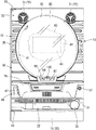
図4と図5に示すように、扉本体フレーム61の略中央部には、遊技盤40の遊技領域42を前方から透視可能な略円形の開口窓62が形成されている。また、扉本体フレーム61の後側には開口窓62よりも大きい矩形枠状をなす窓枠63が設けられ、その窓枠63にはガラス板、透明樹脂板等の透明な窓板65が装着されている。
[About glass doors as opening and closing bodies]
As shown in FIGS. 3 and 4, a
As shown in FIGS. 4 and 5, the
The door
As shown in FIGS. 4 and 5, a substantially
[ガラス扉の前側構成について]
図4に示すように、扉本体フレーム61の前側には、その開口窓62の周縁部の上部に沿って、ユニット化された音響電飾ユニット(トップランプユニット)70がビス等によって装着されている。
音響電飾ユニット70の左右両側部にはスピーカカバー71を前側に有するスピーカ(この実施例では中高音用スピーカ)72が装着されている。
また、音響電飾ユニット70の透明なカバー体によって覆われた状態で複数の光源が配置されたランプ基板(図示しない)が配設されている。
また、図4に示すように、扉本体フレーム61の前側には、その開口窓62の周縁部の左右両側部に沿って左右一対のサイド電飾ユニット73が装着されている。
[About the front side configuration of the glass door]
As shown in FIG. 4, a unitized acoustic decoration unit (top lamp unit) 70 is mounted on the front side of the
Speakers (speakers for middle and high sounds in this embodiment) 72 having a
In addition, a lamp substrate (not shown) on which a plurality of light sources are arranged in a state of being covered with a transparent cover body of the
As shown in FIG. 4, a pair of left and right
[装備ユニットとしての表示ユニットについて]
図4に示すように、扉本体フレーム61の前側には、その開口窓62の周縁部の下部に沿いかつ左右一対のサイド電飾ユニット73の下端部の後側と扉本体フレーム61の前面との間に両端部が挟まれた状態で不透明な合成樹脂材よりなるユニット取付ベース75が配置されている。
そして、扉本体フレーム61の前側、すなわち、ユニット取付ベース75の前面には、装備ユニットとしての表示ユニット80が装着されている。
[Display unit as equipped unit]
As shown in FIG. 4, on the front side of the door
A
表示ユニット80は、遊技機の片側に設置される球貸機(図示しない)のカード挿入口に挿入されたカード(プリペードカード)に記憶されている球貸度数を表示するものであり、図6〜図9に示すように、その前側から後側に向けて前面装飾枠81、ユニット本体90、貸球操作ボタン96、返却操作ボタン97、及び回路基板100を順に備え、これら各部材が相互に組み付けられてユニット化されている。
図7に示すように、表示ユニット80に組み込まれた回路基板100の前面(表面の実装面)の略中央部には、遊技機の片側に設置される球貸機(図示しない)のカード挿入口に挿入されたカード(プリペードカード)に記憶されている球貸度数を7セグメント表示によって表示する度数表示器110が設置され、その左右両側部には、貸球スイッチ111及び返却スイッチ112がそれぞれ設置されている。
The
As shown in FIG. 7, a card of a ball lending machine (not shown) installed on one side of the gaming machine is inserted in the approximate center of the front surface (surface mounting surface) of the
図7〜図9に示すように、前面装飾枠81は、不透明な合成樹脂材によって略四角枠状に形成され、その中央部には、ユニット本体90が嵌込まれて一体に組み付けられる開口部82が形成されている。
また、前面装飾枠81の左右の両枠部の後面には、取付用ボス83が後方に向けて突設されている。
As shown in FIGS. 7 to 9, the front
A mounting
[表示ユニットのユニット本体について]
図7〜図9に示すように、ユニット本体90は、不透明な合成樹脂材によって略四角形状に形成され、前面装飾枠81の開口部82に嵌込まれて一体に組み付けられる。このユニット本体90の略中央部には、回路基板100の度数表示器110に対応する透孔91が形成され、左右両側部には、貸球操作ボタン95と返却操作ボタン96に対応するボタン孔92、93が形成されている。
また、図7に示すように、ユニット本体90の上縁部には、回路基板100の上端部を弾性的に係止する左右一対の基板係止爪94が形成されている。
また、図8に示すように、ユニット本体90の下縁部には、回路基板100の下端部を掛け止めする左右一対の基板係止片95が形成されている。
[Display unit main unit]
As shown in FIGS. 7 to 9, the unit
As shown in FIG. 7, a pair of left and right
Further, as shown in FIG. 8, a pair of left and right
すなわち、ユニット本体90の各ボタン孔92、93に貸球操作ボタン95と返却操作ボタン96とがそれぞれ嵌込まれた状態で、回路基板100の下端部を基板係止片95に掛け止めし、同回路基板100の上端部を基板係止爪94によって弾性的に係止することによって、ユニット本体90の後側に回路基板100が装着される。そして、この状態において、ユニット本体90の透孔91に、回路基板100の度数表示器110が嵌込まれて露出され、貸球操作ボタン95と返却操作ボタン96とが回路基板100の貸球スイッチ111と返却スイッチ112とをスイッチ操作可能に前後方向に所定ストロークだけ移動可能に保持されるようになっている。
That is, with the ball
前記したように、前面装飾枠81、ユニット本体90、貸球操作ボタン96、返却操作ボタン97、及び回路基板100が相互に組み付けられることでユニット化された表示ユニット80が構成される。
そして、図8と図9に示すように、表示ユニット80は、その前面装飾枠81の左右の両取付用ボス83がユニット取付ベース75のボス挿通孔78に挿通された状態で、扉本体フレーム61の後側からその取付孔を通して取付ネジ85が取付用ボス83にねじ込まれることで、扉本体フレーム61のユニット取付ベース75の前側に着脱可能に装着されるようになっている。このようにして、扉本体フレーム61の後側から取付ネジ85を締め付けたリ緩めて外すことによって、扉本体フレーム61の前側にユニット取付ベース75を介して表示ユニット80を容易に着脱することができる。このため、扉本体フレーム61に対し表示ユニット80を取り外した状態で保守・点検、故障時の修理、回路基板100の脱着交換等を容易に行うことができ、サービス性の向上を図ることができる。
As described above, the
As shown in FIGS. 8 and 9, the
図9に示すように、開閉体としてのガラス扉60の扉本体フレーム61の前側に、装備ユニットとしての表示ユニット80が装着された状態において、ガラス扉60が閉じ状態、開き状態、いずれの状態にあっても回路基板100の表裏両面(前後両面)が、同回路基板100の前側に配置された不透明部材としてのユニット本体90と、同回路基板100の後側に配置された不透明部材としての扉本体フレーム61によって覆われるようになっている。
そして、図3と図5に示すように、ガラス扉60が開かれることで、後側の不透明部材としての扉本体フレーム61が視認可能に構成されている。
なお、扉本体フレーム61の後側には、透明な合成樹脂材より形成された透明部品69が装着される場合があり、この場合には透明部品69を透して扉本体フレーム61が視認可能となる。
As shown in FIG. 9, in a state where the
As shown in FIGS. 3 and 5, the
A
[扉本体フレームの透視部と回路基板の基板情報について]
図8に示すように、後側の不透明部材としての扉本体フレーム61には、回路基板100の一面(後面)を局部的に透視可能な角孔状の透視部61aが形成されている。
また、この実施例1においては、回路基板100の後側に位置するユニット取付ベース75に対しても、扉本体フレーム61の透視部61aに対応する位置において切り欠き状の透視部75aが形成されている。
[About the see-through part of the door frame and circuit board information]
As shown in FIG. 8, the
In the first embodiment, a notch-like see-through
一方、図8に示すように、回路基板100の一面(後面の非実装面)には、扉本体フレーム61及びユニット取付ベース75の透視部61a、75aに対応する位置において、基板番号、製造年月日、製造者名、機種名等の基板情報107が表示されている。
図10に示すように、回路基板100は、絶縁材よりなるベース板101の表裏両面には、銅箔によって配線パターン103、106がそれぞれ形成され、その配線パターン103、106が透明な絶縁層104、108によってそれぞれ覆われることで回路基板100が構成されている。
また、回路基板100の一面の基板情報107は、同回路基板100の一面の配線パターン103を形成する銅箔の一部によって形成され、配線パターン103とともに透明な絶縁層104によって覆われている。
On the other hand, as shown in FIG. 8, on one surface (the rear non-mounting surface) of the
As shown in FIG. 10, in the
Further, the
前記したように、回路基板100の一面に配線パターンを形成する銅箔の一部によって基板情報107を形成することで、例えば、回路基板100の一面にシルク印刷等によって基板情報が表示された場合と比較して印刷コストの低減を図ることができる。さらに、基板情報107が透明な絶縁層104によって保護されるため、摩擦等によって基板情報107が消失され難い。
また、回路基板100の反対面(前面の実装面)においては、シルク印刷等によって基板情報が必要に応じて表示される。
As described above, when the
Further, on the opposite surface (front mounting surface) of the
なお、図20に示すように、回路基板100及び球貸機は、接続端子板を介して払出制御基板128にそれぞれ電気的に接続されている。そして、球貸機のカード挿入口に挿入されたカード(プリペードカード)に記憶されている球貸度数が球貸機によって読みとられ、その信号が接続端子板を介して払出制御基板128に伝達される。そして、これに基づいて、払出制御基板128から接続端子板を介して、回路基板100に伝達される制御信号によって、回路基板100の度数表示器110には、カードの球貸度数に対応する表示(7セグメント表示)がなされるようになっている。
As shown in FIG. 20, the
また、貸球操作ボタン96を押圧操作して貸球スイッチ111を作動することで、その信号が接続端子板を介して払出制御基板128に伝達される。これによって、球払出ユニット140の払出モータ160が作動され、所定数の球が遊技機の前側の上皿74に払い出される。さらに、返却操作ボタン97を押圧操作して返却スイッチ112を作動することで、その信号が接続端子板を介して払出制御基板128に伝達される。これによって、球貸機のカード挿入口に挿入されたカードが同カード挿入口から取り出し可能に突出されるようになっている。
Further, when the ball
[実施例1の作用効果について]
上述したように構成されるこの実施例1において、ガラス扉60の所定位置に表示ユニット80が装着された状態において、その表示ユニット80に組み込まれた回路基板100の存在や、同回路基板100が正規のものであるか否かを判断する場合、本体枠20に対し扉開閉用ヒンジ機構59を支点としてガラス扉60が開かれる。
これによって、回路基板100の後側の不透明部材としての扉本体フレーム61の後面が透明部品を透して視認可能となる。
そして、図9に示すように、扉本体フレーム61及びユニット取付ベース75の透視部61a、75aを透して回路基板100の一面が視認されるとともに、同回路基板100一面に表示された基板情報107を視認することによって、その回路基板100が正規のものであるか否かの判断を的確に行うことができる。
このため、回路基板100が不正の回路基板に交換されて不正行為がなされる不具合を防止することができる。
[Effects of Example 1]
In the first embodiment configured as described above, in the state where the
As a result, the rear surface of the door
Then, as shown in FIG. 9, one surface of the
For this reason, the malfunction by which the
特に、この実施例1においては、回路基板100の前側に配置される表示ユニット80の前面装飾枠81及び表示ユニット80を、不透明な合成樹脂材によって形成して外観意匠性を確保することができる。
そして、ガラス扉60の扉本体フレーム61を金属板によって形成して剛性や耐久性を確保しながら、扉本体フレーム61の透視部61aを透して回路基板100の基板情報107を容易に視認することができる。
例えば、仮に、表示ユニット80のユニット本体90を透明な合成樹脂材によって形成し、回路基板100の前面に基板情報107を表示した場合には、そのユニット本体90を透して回路基板100前面の基板情報107を視認することが可能となるが、この場合には、表示ユニット80の内部が視認されることとなり、外観意匠が悪化されるが、この実施例1においては、このような不具合を解消することができる。
In particular, in the first embodiment, the front
And the board |
For example, if the unit
[実施例1の変更例について]
なお、前記実施例1においては、開閉体としてのガラス扉60の扉本体フレーム61に装備ユニットとしての表示ユニット80が装着される場合を例示したが、ガラス扉60の扉本体フレーム61の上部に装着された音響電飾ユニット70や左右一対のサイド電飾ユニット73を装備ユニットとした場合においても、この発明を実施することが可能である。
音響電飾ユニット70や左右一対のサイド電飾ユニット73には、主制御基板131あるいは副制御基板に電気的に接続される回路基板が組み込まれている。
また、図4に示すように、ガラス扉60の扉本体フレーム61の下部片側寄りに装着された演出操作用の操作ユニット46を装備ユニットとした場合においても、この発明を実施することが可能である。
演出操作用の操作ユニット46は、例えば、図柄表示装置45に予め設定された複数の抽選図柄パターンを操作ボタン47の押圧操作によって切り換え可能に構成したり、操作ボタン47の押圧操作によって当り/はずれの予告を表示したりして遊技者の操作が演出表示に反映される操作部であって、遊技者の参加意欲を高揚させることができる。この操作ユニット46には主制御基板131あるいは副制御基板に電気的に接続される回路基板が組み込まれている。
[Modification of Example 1]
In addition, in the said Example 1, although the case where the
A circuit board that is electrically connected to the
In addition, as shown in FIG. 4, the present invention can be implemented even when the
For example, the
次に、この発明の実施例2を図11〜図20にしたがって説明する。
図11は外枠に対し本体枠を開いた状態を斜め左上前方から示す斜視図である。図12は遊技機の後側全体を示す背面図である。図13は本体枠の機構装着体に球払出ユニットが装着された状態を示す側断面図である。図14は球払出ユニットを後側から示す斜視図である。図15は球払出ユニットの構成部材を分離した状態を後側から示す斜視図である。図16は球払出ユニットの構成部材を分離した状態を前側から示す斜視図である。図17は球払出ユニットの背面図である。図18は図17のXVIII−XVIII線に基づく断面図である。図19は球払出ユニットの回路基板を示す断面図である。なお、説明の便宜上、遊技機において遊技者側を前、反対側を後として説明する。
Next, a second embodiment of the present invention will be described with reference to FIGS.
FIG. 11 is a perspective view showing a state in which the main body frame is opened with respect to the outer frame, obliquely from the upper left front. FIG. 12 is a rear view showing the entire rear side of the gaming machine. FIG. 13 is a side sectional view showing a state in which the ball dispensing unit is mounted on the mechanism mounting body of the main body frame. FIG. 14 is a perspective view showing the ball dispensing unit from the rear side. FIG. 15 is a perspective view showing the state in which the constituent members of the ball dispensing unit are separated from the rear side. FIG. 16 is a perspective view showing a state where the constituent members of the ball dispensing unit are separated from the front side. FIG. 17 is a rear view of the ball dispensing unit. 18 is a cross-sectional view based on the line XVIII-XVIII in FIG. FIG. 19 is a cross-sectional view showing a circuit board of the ball dispensing unit. For convenience of explanation, in the gaming machine, the player side will be described as the front and the opposite side as the back.
この発明の実施例2においては、外枠10に開閉可能に設けられかつ遊技盤40が着脱可能に装着される本体枠20を開閉体とし、本体枠20の後側に装着された球払出ユニット140を装備ユニットとした場合を例示する。また、この実施例2に係る遊技機の他の構成は、前記実施例1の遊技機と同様にして構成されるため、同一構成部材に対し同一符号を付記している。
In the second embodiment of the present invention, a ball payout unit mounted on the rear side of the
[本体枠の後側下部の装備について]
図11と図12に示すように、外枠10の前側に本体枠開閉用ヒンジ機構16によって開閉可能に装着された本体枠20において、その前枠体21の後下部領域の片側(図に向かって左側)には、発射ハンマー123、その発射ハンマー123を作動する発射モータ122等が装着されている。
また、遊技機の後側の所定位置には、主制御基板131が収納された主制御基板ボックス130、払出制御基板128が収納された払出制御基板ボックス127が装着されている。
主制御基板131は遊技全般の進行を制御し、払出制御基板128は球(パチンコ球)の払出を制御するものであり、球を払い出す数を記憶するRAMを備え、主制御基板131から送信される払出用信号に従って球を払い出す制御信号を、後述する球払出ユニット140内に組み込まれた中継用の回路基板170に伝達して払出モータ160を作動制御するようになっている。
なお、図20は、前記実施例1の表示ユニット80の回路基板100と、この実施例2の球払出ユニット140の回路基板170、払出制御基板128、主制御基板131の接続状態を示すブロック図である。
[Equipment on the lower rear of the main frame]
As shown in FIGS. 11 and 12, in the
Further, a main
The
FIG. 20 is a block diagram showing a connection state between the
[本体枠の機構装着体、球タンク、タンクレール、球払出ユニット装着部について]
図11と図12に示すように、外枠10の前側に本体枠開閉用ヒンジ機構16によって開閉可能に装着された開閉体としての本体枠20において、その後部に一体に形成された機構装着体23の後側上部には、球タンク135とタンクレール136とがそれぞれ配設されている。
図11と図12に示すように、本体枠20の機構装着体23の片側(図11に向かって右側)寄りの上下方向には、装備ユニットとしての球払出ユニット140に対応する縦長の球払出ユニット装着部25が形成されている。
図13に示すように、球払出ユニット装着部25は、後方に開口する凹状に形成され、その奥壁部(前壁部)29の所定位置には、球払出ユニット140の払出モータ160が遊技盤40の後側に向けて突出可能な開口部29aが形成されている。
[Main body frame mounting body, ball tank, tank rail, ball dispensing unit mounting part]
As shown in FIGS. 11 and 12, in a
As shown in FIGS. 11 and 12, a vertically long ball payout corresponding to a
As shown in FIG. 13, the ball payout
[装備ユニットとしての球払出ユニットについて]
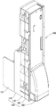
図13に示すように、装備ユニットとしての球払出ユニット140は、ユニット本体141、払出モータ160を駆動源とする払出部材154、回路基板170等が相互に組み付けられてユニット化され、球払出ユニット装着部25の凹部の後方開口部から嵌込まれて適宜の取付手段(例えば、弾性クリップ、係止爪、ビス等の取付手段)によって着脱可能に装着されるようになっている。
[About the ball dispensing unit as an equipment unit]
As shown in FIG. 13, a
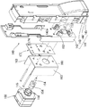
この実施例2において、図14〜図16に示すように、球払出ユニット140のユニット本体141は、前構成体142、中間構成体143、後構成体144及び後カバー体145を備えて構成されている。そして、図17と図18に示すように、前後及び中間の各構成体142、143、144によってタンクレール136の前後のレール通路に出口にそれぞれ連通する流入口を有する球通路150が前後複数列(この実施例では前後2列)に区画されて形成されている。
In the second embodiment, as shown in FIGS. 14 to 16, the unit
また、図17に示すように、ユニット本体141には、その内部に形成された前後複数列の球通路150の下流部が二股状に分岐されて前後複数列の賞球及び貸球用球通路151と球抜き用球通路152とがそれぞれ形成されている。そして、賞球及び貸球用球通路151と球抜き用球通路152との分岐部には、球を賞球及び貸球用球通路151と球抜き用球通路152とのいずれかに振り分けて払い出すための回転体よりなる払出部材154が正逆回転可能に配設されている。
また、球払出ユニット140のユニット本体141の中間構成体143、後構成体144及び後カバー体145は、透明な合成樹脂材により形成され、前構成体142は、不透明な合成樹脂材により形成されている。
これによって、ユニット本体141の球通路150内の球の流れ状態が後カバー体145、後構成体144及び中間構成体143を透して視認可能となっている。
In addition, as shown in FIG. 17, the unit
Further, the
Thereby, the flow state of the sphere in the
また、この実施例において、図17と図18に示すように、前後複数列の球通路150の分岐部近傍には、球通路150を流れる球を払出部材154の直上に流下案内する左右対をなすガイド体153が軸153aを中心として回動可能に配設されている。これら対のガイド体153の間に跨ってばね155が張設されている。これによって、対のガイド体153が所定の球案内姿勢に保持されるようになっている。また、後カバー体145を開放又は取り外すことによって、対のガイド体153の作動不良、例えば、ばね155の両端部の掛け止め作業や交換作業が容易に行われるようになっている。
In this embodiment, as shown in FIGS. 17 and 18, in the vicinity of the branching portion of the front and rear rows of the
[球払出ユニットの中継用の回路基板及び払出モータについて]
図15と図16に示すように、ユニット本体141の前構成体142の前側には、払出制御基板128から送信される払出用信号を払出モータ160に伝達する中継用の回路基板170が配置されている。
ユニット本体141の前構成体142の前側には、中継用の回路基板170を収納する空間部を隔ててモータ用取付板(ブラケット)161が装着されている。この取付板161には、払出部材154をその中心部の回転軸164において正逆方向に回転駆動するための電動アクチュエータとしての払出モータ160が装着されている。
図13に示すように、払出モータ160は、球払出ユニット装着部25の奥壁部29の開口部29aを通して遊技盤40の後面に向けて突出している。
そして、払出モータ160の作動による回転軸164の正回転時には、これに基づいて正回転する払出部材154によって球が賞球及び貸球用球通路151に払い出される。
また、払出制御基板128上に配置された図示しない球抜きスイッチを操作することで、払出モータ160によって回転軸164が逆回転し、これに基づいて逆回転する払出部材154によって球が球抜き用球通路152に排出されるようになっている。
[Relay circuit board and dispensing motor for ball dispensing unit]
As shown in FIGS. 15 and 16, a
A motor mounting plate (bracket) 161 is mounted on the front side of the front
As shown in FIG. 13, the
When the
Further, by operating a ball removal switch (not shown) arranged on the dispensing
また、この実施例2においては、図15と図16に示すように、払出モータ160の取付板161の左右両側部には同払出モータ160の両側方に沿って側壁部163が形成されている。そして、これら両側壁部163によって払出モータ160が保護されるとともに、同払出モータ160の熱が取付板161の両側壁部163に伝導されて放熱され、これによって払出モータ160の過熱による損傷を防止するようになっている。
Further, in the second embodiment, as shown in FIGS. 15 and 16,
また、図15、図16及び図18に示すように、払出モータ160の回転軸164の軸上には、前構成体142の前側に位置しかつ光学式検出器(フォトセンサ)166によって回転状態が検出される回転盤よりなる被検出体165が回転軸164と一体状をなして設けられている。この被検出体165の外周部には複数のスリット、切欠部等の被検出部が設けられている。
また、光学式検出器166は、中継用の回路基板170の前面(実装面)の所定位置に設置されており、被検出体165の外周部が挿通される溝を隔てて発光素子と受光素子とを対向状に備えている。
As shown in FIGS. 15, 16, and 18, on the axis of the
The
なお、光学式検出器166によって被検出体(すなわち、払出モータ160、回転軸164及び払出部材154)165の回転不良が検出されると、その検出信号が払出制御基板128に伝達され、これに基づいて払出制御基板128から出力される制御信号によって払出モータ160が回転不良の動作を開始する。例えば、球噛み等による回転不良を想定して払出モータ160が所定時間において、正逆回転を繰り返す動作が開始され、これによって球噛み等による回転不良が解消されるようになっている。
また、光学式検出器166の検出信号が払出制御基板128に伝達されると、遊技機の所定位置に設置された報知手段(図示しない)が作動し、例えば、ランプが点灯又は点滅したり、あるいはスピーカが作動することによって、払出モータ160、回転軸164及び払出部材154の回転不良(作動不良)が報知される。また、前記した検出信号(異常信号)をホールコンピュータに出力することも可能である。
When the
Further, when the detection signal of the
前記したように、ユニット本体141、払出部材154、払出モータ160、回路基板170等が相互に組み付けられることでユニット化された球払出ユニット140が構成される。
そして、球払出ユニット140は、そのユニット本体141において、本体枠20の球払出ユニット装着部25の凹部の後方開口部から嵌込まれて適宜の取付手段(例えば、弾性クリップ、係止爪、ビス等の取付手段)によって着脱可能に装着されるようになっている。
As described above, the unit
The
図13に示すように、開閉体としての本体枠20の球払出ユニット装着部25の凹部に、装備ユニットとしての球払出ユニット140が装着された状態において、本体枠20が閉じ状態、開き状態、いずれの状態にあっても回路基板170の表裏両面(前後両面)が、同回路基板170の前側に配置された不透明部材としての本体枠20と、同回路基板170の後側に後側に配置された不透明部材としての前構成体142によって覆われるようになっている。
そして、図11に示すように、外枠10に対し本体枠開閉用ヒンジ機構16を支点として本体枠20が開かれることで、図13に示すように、回路基板170の後側の不透明部材としての前構成体142が、透明な中間構成体143及び後構成体144を透して視認可能に構成されている。
As shown in FIG. 13, in a state where the
Then, as shown in FIG. 11, the
[ユニット本体の前構成体の透視部と回路基板の基板情報について]
図15に示すように、後側の不透明部材としてのユニット本体141の前構成体142には、回路基板170の一面(後面)を局部的に透視可能な角孔状の透視部142aが形成されている。
[About the see-through part of the front structure of the unit body and the board information of the circuit board]
As shown in FIG. 15, the
一方、図15に示すように、回路基板170の一面(後面の非実装面)には、前構成体142の透視部142aに対応する位置において、基板番号、製造年月日、製造者名、機種名等の基板情報174が表示されている。
図19に示すように、回路基板170は、絶縁材よりなるベース板171の一面(後面)には、銅箔によって配線パターン173が形成され、その配線パターン173が透明な絶縁層175によって覆われることで回路基板170が構成されている。
また、回路基板170の一面の基板情報174は、同回路基板170の一面の配線パターン173を形成する銅箔の一部によって形成され、配線パターン173とともに透明な絶縁層175によって覆われている。
On the other hand, as shown in FIG. 15, on one surface (rear non-mounting surface) of the
As shown in FIG. 19, the
Further, the
前記したように、回路基板170の一面に、配線パターン173を形成する銅箔の一部によって基板情報174を形成することで、例えば、回路基板170の一面にシルク印刷等によって基板情報が表示された場合と比較して印刷コストの低減を図ることができる。さらに、基板情報174が透明な絶縁層175によって保護されるため、摩擦等によって基板情報174が消失され難い。
また、回路基板170の反対面(前面の実装面)においては、シルク印刷等によって基板情報が必要に応じて表示される。
なお、図20に示すように、払出制御基板128に電気的に接続された回路基板170には、光学式検出器166の他、球払出ユニット140に組み付けられた払出モータ160や払出計数スイッチ、球切れスイッチが電気的に接続されている。
As described above, by forming the
Further, on the opposite surface (front mounting surface) of the
As shown in FIG. 20, the
[実施例2の作用効果について]
上述したように構成されるこの実施例2において、本体枠20の後側の機構装着体23の球払出ユニット装着部25に球払出ユニット140が装着された状態において、球払出ユニット140に組み込まれた回路基板170の存在や、同回路基板170が正規のものであるか否かを判断する場合、図12に示すように、外枠10に対し本体枠開閉用ヒンジ機構16を支点として本体枠20が開かれる。
これによって、図18に示すように、回路基板170の後側の不透明部材としての球払出ユニット140の前構成体142の後面が透明な後構成体144及び中間構成体143を透して視認可能となる。
そして、前構成体142の透視部142aを透して回路基板170の一面が視認されるとともに、同回路基板170一面に表示された基板情報174を視認することによって、その回路基板170が正規のものであるか否かの判断を的確に行うことができる。
このため、回路基板170が不正の回路基板に交換されて不正行為がなされる不具合を防止することができる。
[Effects of Example 2]
In the second embodiment configured as described above, the
As a result, as shown in FIG. 18, the rear surface of the
Then, one surface of the
For this reason, it is possible to prevent a problem in which the
特に、この実施例2においては、球払出ユニット140の前構成体142を不透明な合成樹脂材によって形成することによって、前構成体142の前側に配置されている部品を隠すことができ、ユニット本体141の球通路150内の球の流れ状態を透明な後カバー体145、後構成体144及び中間構成体143を透して容易に視認することができる。
しかも、不透明な前構成体142によって、球払出ユニット140の後方から後構成体144及び中間構成体143を透して球通路150に入射する光を遮光することができ、不透明な前構成体142の前側に配置された回路基板170の光学式検出器166が球払出ユニット140の後方からの光によって誤動作される不具合を防止することができる。
In particular, in the second embodiment, by forming the
In addition, the
[この発明の他の実施例について]
なお、この発明は前記実施例1及び2に限定するものではない。
例えば、前記実施例1及び2においては、前枠体21、遊技盤装着枠22及び機構装着体23が不透明な合成樹脂材によって一体成形されることで本体枠20が構成される場合を例示したが、遊技盤が着脱可能に装着される遊技盤装着枠が一体に形成されたりあるいは別体の遊技盤装着枠が組み付けられる前枠体が本体枠である場合においてもこの発明を実施することができる。
また、前記実施例1及び2においては、球(パチンコ球)を用いて遊技を行う遊技機(例えば、パチンコ機)である場合を例示したが、メダルを用いて遊技を行う遊技機(例えば、スロットマシン)においてもこの発明を実施することができる。
[Other Embodiments of the Invention]
The present invention is not limited to the first and second embodiments.
For example, in the first and second embodiments, the case where the
In the first and second embodiments, a case where a game machine (for example, a pachinko machine) is used to play a game using a ball (pachinko ball) is exemplified. However, a game machine (for example, a game machine that uses a medal to play a game) The present invention can also be implemented in a slot machine.
10 外枠
16 本体枠開閉用ヒンジ機構
20 本体枠(開閉体)
40 遊技盤
42 遊技領域
60 ガラス扉(開閉体)
61 扉本体フレーム
80 表示ユニット
100 回路基板
140 球払出ユニット
170 回路基板
DESCRIPTION OF
40
61
Claims (1)
A gaming machine, wherein an equipment unit is mounted at a predetermined position of an openable / closable opening / closing body, and a circuit board is incorporated in the equipment unit.
Priority Applications (1)
| Application Number | Priority Date | Filing Date | Title |
|---|---|---|---|
| JP2004217415A JP2006034513A (en) | 2004-07-26 | 2004-07-26 | Game machine |
Applications Claiming Priority (1)
| Application Number | Priority Date | Filing Date | Title |
|---|---|---|---|
| JP2004217415A JP2006034513A (en) | 2004-07-26 | 2004-07-26 | Game machine |
Publications (2)
| Publication Number | Publication Date |
|---|---|
| JP2006034513A true JP2006034513A (en) | 2006-02-09 |
| JP2006034513A5 JP2006034513A5 (en) | 2009-04-30 |
Family
ID=35900149
Family Applications (1)
| Application Number | Title | Priority Date | Filing Date |
|---|---|---|---|
| JP2004217415A Pending JP2006034513A (en) | 2004-07-26 | 2004-07-26 | Game machine |
Country Status (1)
| Country | Link |
|---|---|
| JP (1) | JP2006034513A (en) |
Cited By (4)
| Publication number | Priority date | Publication date | Assignee | Title |
|---|---|---|---|---|
| JP2008253339A (en) * | 2007-03-31 | 2008-10-23 | Daiichi Shokai Co Ltd | Game machine |
| JP2010063492A (en) * | 2008-09-08 | 2010-03-25 | Aiwa Raito:Kk | Front door frame |
| JP2019154626A (en) * | 2018-03-09 | 2019-09-19 | 株式会社大一商会 | Game machine |
| JP2019154625A (en) * | 2018-03-09 | 2019-09-19 | 株式会社大一商会 | Game machine |
Citations (6)
| Publication number | Priority date | Publication date | Assignee | Title |
|---|---|---|---|---|
| JPH09299553A (en) * | 1996-05-09 | 1997-11-25 | Sankyo Kk | Circuit board for game machine |
| JPH09308763A (en) * | 1996-05-23 | 1997-12-02 | Kyoraku Sangyo Kk | Ball dispensing device for pachinko game machine |
| JPH1094655A (en) * | 1996-09-24 | 1998-04-14 | Daiichi Shokai Co Ltd | Pachinko machine |
| JPH11276694A (en) * | 1998-03-27 | 1999-10-12 | Sankyo Kk | Game machine |
| JP2001046718A (en) * | 1999-08-12 | 2001-02-20 | Sankyo Kk | Pachinko game machine |
| JP2002045552A (en) * | 2000-08-04 | 2002-02-12 | Adachi Light Co Ltd | Pachinko game machine |
-
2004
- 2004-07-26 JP JP2004217415A patent/JP2006034513A/en active Pending
Patent Citations (6)
| Publication number | Priority date | Publication date | Assignee | Title |
|---|---|---|---|---|
| JPH09299553A (en) * | 1996-05-09 | 1997-11-25 | Sankyo Kk | Circuit board for game machine |
| JPH09308763A (en) * | 1996-05-23 | 1997-12-02 | Kyoraku Sangyo Kk | Ball dispensing device for pachinko game machine |
| JPH1094655A (en) * | 1996-09-24 | 1998-04-14 | Daiichi Shokai Co Ltd | Pachinko machine |
| JPH11276694A (en) * | 1998-03-27 | 1999-10-12 | Sankyo Kk | Game machine |
| JP2001046718A (en) * | 1999-08-12 | 2001-02-20 | Sankyo Kk | Pachinko game machine |
| JP2002045552A (en) * | 2000-08-04 | 2002-02-12 | Adachi Light Co Ltd | Pachinko game machine |
Cited By (6)
| Publication number | Priority date | Publication date | Assignee | Title |
|---|---|---|---|---|
| JP2008253339A (en) * | 2007-03-31 | 2008-10-23 | Daiichi Shokai Co Ltd | Game machine |
| JP2010063492A (en) * | 2008-09-08 | 2010-03-25 | Aiwa Raito:Kk | Front door frame |
| JP2019154626A (en) * | 2018-03-09 | 2019-09-19 | 株式会社大一商会 | Game machine |
| JP2019154625A (en) * | 2018-03-09 | 2019-09-19 | 株式会社大一商会 | Game machine |
| JP7239131B2 (en) | 2018-03-09 | 2023-03-14 | 株式会社大一商会 | game machine |
| JP7239130B2 (en) | 2018-03-09 | 2023-03-14 | 株式会社大一商会 | game machine |
Similar Documents
| Publication | Publication Date | Title |
|---|---|---|
| JP5463121B2 (en) | Game machine | |
| JP4756538B2 (en) | GAME MEMBER AND GAME MACHINE HAVING THE SAME | |
| JP6401461B2 (en) | Game machine | |
| JP5630835B2 (en) | Game machine | |
| JP6839344B2 (en) | Game machine | |
| JP4726819B2 (en) | Amusement stand | |
| JP6931157B2 (en) | Pachinko machine | |
| JP2010201107A (en) | Game machine | |
| JPH11333060A (en) | Game machine | |
| JP5500599B2 (en) | Game machine | |
| JP2006034513A (en) | Game machine | |
| JP2020099818A (en) | Game machine | |
| JP5439142B2 (en) | Game machine | |
| JP2018130307A (en) | Game machine | |
| JP2008237512A (en) | Fraudulent operation preventing structure of game machine | |
| JP4204998B2 (en) | Enclosed ball game machine | |
| JP2008048918A (en) | Game machine | |
| JP2007050029A (en) | Game machine | |
| JP2006230524A (en) | Game machine | |
| EP1417992B1 (en) | Gaming machine | |
| JP2020099817A (en) | Game machine | |
| JP5146842B2 (en) | Sealing structure of game board control board | |
| JP6931156B2 (en) | Pachinko machine | |
| JPH11333102A (en) | Pachinko machine | |
| JP6942320B2 (en) | Pachinko machine |
Legal Events
| Date | Code | Title | Description |
|---|---|---|---|
| A621 | Written request for application examination |
Free format text: JAPANESE INTERMEDIATE CODE: A621 Effective date: 20060531 |
|
| RD05 | Notification of revocation of power of attorney |
Free format text: JAPANESE INTERMEDIATE CODE: A7425 Effective date: 20080715 |
|
| A521 | Written amendment |
Free format text: JAPANESE INTERMEDIATE CODE: A523 Effective date: 20090312 |
|
| A131 | Notification of reasons for refusal |
Free format text: JAPANESE INTERMEDIATE CODE: A131 Effective date: 20091201 |
|
| A977 | Report on retrieval |
Effective date: 20091202 Free format text: JAPANESE INTERMEDIATE CODE: A971007 |
|
| A02 | Decision of refusal |
Free format text: JAPANESE INTERMEDIATE CODE: A02 Effective date: 20100406 |