本発明は、遊技機のハーネスクランプ構造に関する。
The present invention relates to a harness clamp structure for a gaming machine.
従来から、遊技者に娯楽を提供する遊技機として、外周面に複数種類の図柄が記された複数の回転リールを備え、回転状態の回転リールを遊技者に停止させて図柄を揃えさせる遊技を行うスロットマシンが利用されている。このようなスロットマシンは、六面体の箱状に形成されるとともに、前面が開口された筐体と、この筐体の前面の開口を塞ぐ前扉とを備えたものとなっている。
Conventionally, as a gaming machine that provides amusement to a player, a game that has a plurality of rotating reels with a plurality of types of symbols on the outer peripheral surface and causes the player to stop rotating rotating reels to align the symbols The slot machine to be used is used. Such a slot machine is formed in a hexahedron box shape, and includes a housing whose front surface is opened and a front door that closes the opening on the front surface of the housing.
そして、スロットマシンの筐体の内部には、前述の回転リールを有するリールユニット、遊技用のメダルを遊技者に払い出すためのホッパーユニット、並びに、リールユニット及びホッパーユニット等の動作を制御するための制御装置等が収納されている。また、スロットマシンの前扉には、遊技媒体としてのメダルが投入される投入口、並びに、回転リールの回転を開始させるために操作されるスタートスイッチ、及び、回転リールの回転を停止させるために操作されるストップスイッチ等の操作用のスイッチが設けられている。
In the slot machine housing, the reel unit having the above-described rotating reel, the hopper unit for paying out a game medal to the player, and the operation of the reel unit and the hopper unit are controlled. The control device is housed. Also, the slot machine has a front door for inserting a medal as a game medium, a start switch operated to start the rotation of the rotating reel, and a rotation of the rotating reel. An operation switch such as a stop switch to be operated is provided.
ここで、スロットマシンの前扉としては、遊技場で古い機種から新しい機種への機種変更が、既存のスロットマシンの部品交換で行えるように、前扉を複数の部品に分割し、それらを個々に交換可能としたスロットマシンが知られている。すなわち、前扉は、上端からスタートスイッチ等が設けられた操作部までの部分を構成する上部マスクユニットと、この上部マスクユニットよりも下方の部分を構成する下部マスクユニットとの二つに分割されたものとなっている。これらの上部マスクユニット及び下部マスクユニットの両方の裏面には、長方形の枠状に形成されたベース枠体が接合されている。上部マスクユニット及び下部マスクユニットは、このベース枠体によって相互に連結されたものとなっている。
Here, as the front door of the slot machine, the front door is divided into multiple parts so that the model change from the old model to the new model can be done by replacing the parts of the existing slot machine. There are known slot machines that can be replaced. In other words, the front door is divided into two parts: an upper mask unit that constitutes a part from the upper end to the operation part provided with the start switch and the like, and a lower mask unit that constitutes a part below the upper mask unit. It has become. A base frame formed in a rectangular frame shape is bonded to the back surfaces of both the upper mask unit and the lower mask unit. The upper mask unit and the lower mask unit are connected to each other by the base frame.
そして、上部マスクユニットには、スタートスイッチやストップスイッチ等のスイッチが取り付けられている前述の操作部に加えて、内部の回転リールを外部に見せるためのリール窓が設けられるとともに、前扉の裏側に設置される液晶表示装置の画面を外部に見せるための画面表示窓が形成された化粧枠体が取り付けられるようになっている。
The upper mask unit is provided with a reel window for showing the internal rotating reel to the outside in addition to the above-described operation unit to which switches such as a start switch and a stop switch are attached, and the back side of the front door. A decorative frame body on which a screen display window for showing a screen of a liquid crystal display device installed on the outside is formed is attached.
下部マスクユニットには、スロットマシンの機種名入りのパネルが着脱可能に設けられているとともに、ホッパーユニットから払い出されるメダルを受ける受皿が形成されている。ベース枠体には、長方形状の両側に配置されているとともに上下方向に延びる一対の縦材の途中部分同士を連結する補強ステーが設けられている。
The lower mask unit is detachably provided with a panel with a model name of the slot machine, and a tray for receiving medals paid out from the hopper unit is formed. The base frame body is provided with reinforcing stays that are arranged on both sides of the rectangular shape and connect intermediate portions of a pair of vertical members extending in the vertical direction.
補強ステーは、裏側に設置される液晶表示装置の重さでベース枠体が変形しないように、ベース枠体の補強を行うものとなっている。具体的には、ベース枠体の裏側に液晶表示装置を設置するにあたり、液晶表示装置をベース枠体の上辺となる横材と補強ステーとの両方に跨らせ、この状態で液晶表示装置がベース枠体に取り付けられるようになっている。これにより、液晶表示装置の重量が補強ステーにも分散され、液晶表示装置の重さでベース枠体が変形することが未然に防止されるようになっている。
The reinforcing stay reinforces the base frame so that the base frame is not deformed by the weight of the liquid crystal display device installed on the back side. Specifically, when installing the liquid crystal display device on the back side of the base frame body, the liquid crystal display device is straddled over both the cross member and the reinforcing stay on the upper side of the base frame body. It can be attached to the base frame. As a result, the weight of the liquid crystal display device is also distributed to the reinforcing stay, and the base frame body is prevented from being deformed by the weight of the liquid crystal display device.
このようなスロットマシンおいては、機体内部に各種電気部品・各種電子回路基板を備えている。そして、それらが相互に配線(ハーネス)により接続されている。機体内部における配線を結束するものとして、ハーネスクランプが用いられることがある。例えば、特許文献1には、簡単な構造かつ軽量化を図ることができ、配線の損傷を防止し得るとされるハーネスクランプが開示されている。
In such a slot machine, various electrical components and various electronic circuit boards are provided inside the machine body. And they are mutually connected by wiring (harness). A harness clamp may be used to bind the wiring inside the machine body. For example, Patent Document 1 discloses a harness clamp that can achieve a simple structure and light weight and can prevent damage to wiring.
実開平7−3695号公報Japanese Utility Model Publication No. 7-3695
スロットマシン等の遊技機では、筐体に対し前扉が開閉するように構成されている。例えば、筐体側に配置された回路基板と前扉側に配置された電気部品とを接続する配線は、前扉の開閉時に一定量移動する必要がある。また、配線が接続された電気部品が取り付けられた内部構造品(ユニット)を取り外したり移動したりしてメンテナンスをする場合もあり、そのような場合にも、配線が移動可能である必要がある。
A gaming machine such as a slot machine is configured such that a front door is opened and closed with respect to a housing. For example, the wiring that connects the circuit board disposed on the housing side and the electrical components disposed on the front door side needs to move a certain amount when the front door is opened and closed. In some cases, maintenance may be performed by removing or moving the internal structural unit (unit) to which the electrical component to which the wiring is connected is attached. In such a case, the wiring needs to be movable. .
しかしながら、ハーネスクランプが配線を結束するものであると、配線が移動できないか、移動量が限定的に制限され、無理に前扉を開閉したり内部構造品を取り外したりすると、配線の切断や部品の一部の破損を招いてしまうおそれがある。また、ハーネスクランプで配線を結束すると、その結束部分が外部から視認困難となってしまうので、その部分の配線に対する不正行為の早期発見が困難になるという問題もある。
However, if the harness clamp binds the wires, the wires cannot move or the amount of movement is limited, and if the front door is forcibly opened / closed or the internal structure is removed, the wires may be cut or There is a risk of causing some damage. In addition, when wiring is bundled with a harness clamp, it is difficult to visually recognize the bound portion from the outside, and there is also a problem that early detection of fraudulent acts on the wiring of that portion becomes difficult.
そこで、本願は、配線の通過経路を規制しつつ配線の通過方向に沿った移動を許容し、配線や部品の破損を防止し得ると共に、配線に対する不正行為の早期発見に寄与することのできる遊技機のハーネスクランプ構造を提供することを例示的課題とする。
Therefore, the present application allows a movement along the direction of passage of the wiring while restricting the passage route of the wiring, can prevent damage to the wiring and parts, and can contribute to early detection of illegal acts on the wiring. It is an exemplary problem to provide a harness clamp structure of a machine.
上記の課題を解決するために、本発明の例示的側面としての遊技機のハーネスクランプ構造は、配線の通過経路を規制するためのハーネスクランプを内部に有する遊技機であって、ハーネスクランプは、遊技機内のいずれかの位置に取り付けるための取付部と、配線を通過させる配線通過部と、を有し、配線通過部の、配線通過方向に直交する直交面内における断面積が、少なくとも配線通過方向に沿った配線の移動を許容する程度に、直交面内における配線の断面積よりも大きくされ、配線通過部の少なくとも一部が透光性を有して、配線通過部を通過する配線が配線通過部の外側から視認可能とされている。
In order to solve the above problems, a harness clamp structure of a gaming machine as an exemplary aspect of the present invention is a gaming machine having a harness clamp for restricting a passage route of wiring therein, and the harness clamp includes: There is an attachment portion for attachment at any position in the gaming machine and a wiring passage portion for allowing wiring to pass, and the cross-sectional area of the wiring passage portion in an orthogonal plane orthogonal to the wiring passage direction is at least wiring passage The wiring that is larger than the cross-sectional area of the wiring in the orthogonal plane to allow the movement of the wiring along the direction, at least a part of the wiring passage portion is translucent, and the wiring that passes through the wiring passage portion It is visible from the outside of the wiring passage part.
本発明の更なる目的又はその他の特徴は、以下添付図面を参照して説明される好ましい実施の形態によって明らかにされるであろう。
Further objects and other features of the present invention will become apparent from the preferred embodiments described below with reference to the accompanying drawings.
本発明によれば、配線の通過経路を規制しつつ配線の通過方向に沿った移動を許容し、配線や部品の破損を防止し得ると共に、配線に対する不正行為の早期発見に寄与することができる。
ADVANTAGE OF THE INVENTION According to this invention, while restrict | limiting the passage route of wiring, the movement along the passage direction of wiring can be permitted, damage to wiring and components can be prevented, and it can contribute to early detection of fraudulent acts on wiring. .
遊技機を右斜め上方から見た外観斜視図である。It is the external appearance perspective view which looked at the game machine from diagonally upward right.
遊技機を背面側から見た背面図である。It is the rear view which looked at the gaming machine from the back side.
フロント枠をキャビネットに対して前方開放した状態を示す外観図である。It is an external view which shows the state which open | released the front frame with respect to the cabinet.
把手を説明するための説明図であって、(a)は遊技機の右側面図であり、(b)は、把手の変形例を示す断面図である。It is explanatory drawing for demonstrating a handle, Comprising: (a) is a right view of a game machine, (b) is sectional drawing which shows the modification of a handle.
遊技機の内部構造を示す斜視図である。It is a perspective view which shows the internal structure of a game machine.
ハーネスクランプの拡大図である。It is an enlarged view of a harness clamp.
遊技機のドアセンサ近傍を示す外観図である。It is an external view which shows the door sensor vicinity of a game machine.
遊技機のキャビネットとフロント枠とを閉鎖した状態を示すドアセンサ近傍の断面図である。It is sectional drawing of the door sensor vicinity which shows the state which closed the cabinet and front frame of the gaming machine.
フロント枠を背面側の斜め上方から見た斜視図である。It is the perspective view which looked at the front frame from diagonally upward on the back side.
遊技機のキャビネット内部に配置されるリール装置の分解斜視図である。It is a disassembled perspective view of the reel apparatus arrange | positioned inside the cabinet of a game machine.
リールの分解斜視図であって、リール全体を右斜め上方から見た図である。It is the exploded perspective view of a reel, and is the figure which looked at the whole reel from diagonally right above.
リールの分解斜視図であって、リールテープユニットを省略してリールを左斜め後方から見た図である。It is the exploded perspective view of a reel, and is the figure which omitted the reel tape unit and was seen from the diagonally left rear.
遊技機の補助金庫近傍を拡大して示す部分拡大図である。It is the elements on larger scale which expand and show the auxiliary safe vicinity of a game machine.
補助金庫を左斜め上方から見た斜視図である。It is the perspective view which looked at the auxiliary safe from diagonally upper left.
遊技機のメイン基板(主制御基板)近傍を拡大して示す部分拡大図である。It is the elements on larger scale which expand and show the main board (main control board) neighborhood of a game machine.
メイン基板ユニットの概略構成を示す分解斜視図である。It is a disassembled perspective view which shows schematic structure of a main board | substrate unit.
メイン基板ユニットの正面図である。It is a front view of a main board unit.
遊技機のホッパー近傍を拡大して示す部分拡大図である。It is the elements on larger scale which expand and show the hopper vicinity of a game machine.
ホッパーを左後方斜め上から見た外観斜視図である。It is the external appearance perspective view which looked at the hopper from the left back diagonally.
ホッパーの払出部を右前方斜め上から見た外観斜視図であって、一部を分解して示した図である。It is the external appearance perspective view which looked at the discharge part of the hopper from the right front diagonally, Comprising: It is the figure which decomposed | disassembled and showed one part.
ホッパーの底面図である。It is a bottom view of a hopper.
ホッパーにおける放出口近傍のメダル厚み方向における断面図である。It is sectional drawing in the medal thickness direction of the discharge opening vicinity in a hopper.
遊技機の電源ユニット近傍を拡大して示す部分拡大図である。It is the elements on larger scale which expand and show the power supply unit vicinity of a game machine.
電源ユニットの外観斜視図である。It is an external appearance perspective view of a power supply unit.
(a)は、電源ユニットを右側方から見た側面図であり、(b)は電源ユニットのB−B断面図であり、(c)は電源ユニットのC−C断面図である。(A) is the side view which looked at the power supply unit from the right side, (b) is BB sectional drawing of a power supply unit, (c) is CC sectional drawing of a power supply unit.
電源ユニットを上方から見た平面図である。It is the top view which looked at the power supply unit from upper direction.
遊技機のフロント枠の分解斜視図である。It is a disassembled perspective view of the front frame of a game machine.
フレームを斜め前方から見た外観斜視図である。It is the external appearance perspective view which looked at the flame | frame from diagonally forward.
右側のサイドレンズユニットを斜め後方から見た外観斜視図である。It is the external appearance perspective view which looked at the right side lens unit from diagonally backward.
操作パネルユニットを斜め後方から見た外観斜視図である。It is the external appearance perspective view which looked at the operation panel unit from diagonally back.
受皿の一部(右側部分)を斜め後方から見た部分斜視図である。It is the fragmentary perspective view which looked at a part (right side part) of the saucer from diagonally back.
上部レンズユニットを斜め後方から見た外観斜視図である。It is the external appearance perspective view which looked at the upper lens unit from diagonally back.
フロント枠における操作パネルユニット近傍を分解して示す分解斜視図である。It is a disassembled perspective view which decomposes | disassembles and shows the operation panel unit vicinity in a front frame.
フロント枠における受皿ベースプレート近傍を拡大して示す拡大斜視図である。It is an expansion perspective view which expands and shows the saucer baseplate vicinity in a front frame.
操作パネルユニットにおける下マスクユニット近傍の分解斜視図である。It is a disassembled perspective view of the vicinity of the lower mask unit in the operation panel unit.
フロント枠における下部スピーカユニット近傍を分解して示す分解斜視図である。It is a disassembled perspective view which decomposes | disassembles and shows the lower speaker unit vicinity in a front frame.
上部スピーカユニットを分解して示す分解斜視図である。It is a disassembled perspective view which decomposes | disassembles and shows an upper speaker unit.
上部スピーカと後方カバーとの取付状態を示す図であって、(a)は斜視図、(b)は断面図である。It is a figure which shows the attachment state of an upper speaker and a back cover, Comprising: (a) is a perspective view, (b) is sectional drawing.
フロント枠における鍵穴近傍を斜視した拡大斜視図である。It is the expansion perspective view which looked at the keyhole vicinity in a front frame.
錠前ユニットの概略構成を示す分解図である。It is an exploded view which shows schematic structure of a lock unit.
フレームの右上部近傍を右斜め後方から見た斜視図である。It is the perspective view which looked at the upper right part vicinity of the flame | frame from diagonally right back.
シリンダユニットにおける断面図である。It is sectional drawing in a cylinder unit.
操作パネルユニットの分解斜視図である。It is a disassembled perspective view of an operation panel unit.
ベットボタンユニットの拡大斜視図である。It is an expansion perspective view of a bet button unit.
ベットボタンユニットの膨出部への取付け状態を示す構造図である。It is a structural diagram which shows the attachment state to the bulging part of a bet button unit.
ベットボタンユニットを下面側から見た外観斜視図である。It is the external appearance perspective view which looked at the bet button unit from the lower surface side.
ベットボタンユニットのユニット本体を省略して上方から見た斜視図である。It is the perspective view which abbreviate | omitted the unit main body of the bet button unit and was seen from the upper direction.
ストップボタンユニットを右斜め後方から見た外観斜視図である。It is the external appearance perspective view which looked at the stop button unit from diagonally right rear.
センサユニット部分を右斜め前方から見た斜視図である。It is the perspective view which looked at the sensor unit part from diagonally forward right.
遊技機におけるセレクタユニット近傍の分解斜視図である。It is a disassembled perspective view of the vicinity of the selector unit in the gaming machine.
セレクタユニット内部のメダル通路を示す内部構造図である。It is an internal structure figure which shows the medal path inside a selector unit.
セレクタユニット取付ブラケットを後方から見た後面図である。It is the rear view which looked at the selector unit attachment bracket from back.
中央表示基板近傍の分解斜視図である。It is a disassembled perspective view of the center display board | substrate vicinity.
基板ケースの右後方を斜め下方から斜視した斜視図である。It is the perspective view which looked at the right rear of a substrate case from diagonally downward.
遊技機の返却通路近傍の分解斜視図である。It is a disassembled perspective view of the return path vicinity of a gaming machine.
通路部材の外観図である。It is an external view of a channel member.
遊技機の操作パネルユニットのフレームへの取付構造を示す断面図である。It is sectional drawing which shows the attachment structure to the flame | frame of the operation panel unit of a game machine.
操作パネルユニットにおける膨出部(操作パネル部)近傍の部分斜視図である。It is a fragmentary perspective view of the bulging part (operation panel part) vicinity in an operation panel unit.
サイドレンズユニットの内部構造の概略を示す分解斜視図である。It is a disassembled perspective view which shows the outline of the internal structure of a side lens unit.
上部照明ユニットにおけるLED基板、分光プレート、拡散部材の配置を示す配置図である。It is an arrangement drawing showing arrangement of an LED substrate, a spectral plate, and a diffusion member in the upper illumination unit.
遊技機における中央パネルユニットの分解図である。It is an exploded view of the center panel unit in a gaming machine.
遊技機におけるフレームを右斜め後方から見た斜視図である。It is the perspective view which looked at the flame | frame in a game machine from diagonally right backward.
遊技機における上部レンズユニットの分解図であって、右斜め前方から矢視した図である。It is the exploded view of the upper lens unit in a game machine, and is the figure seen from the right diagonally forward.
遊技機における上部レンズユニットの分解図であって、右斜め後方から矢視した図である。It is the exploded view of the upper lens unit in a gaming machine, and is the figure seen from the right diagonally back.
演出基板部を右斜め後方から見た斜視図である。It is the perspective view which looked at the production board part from diagonally right rear.
演出基板部の分解斜視図である。It is a disassembled perspective view of a production board part.
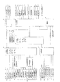
この遊技機における各種基板及び電気装置の接続の様子を示すブロック構成図である。It is a block block diagram which shows the mode of the connection of the various board | substrates and electrical apparatuses in this game machine.
実施するための形態Form to carry out
<A.筐体の構造>
<A−0.全体の概略説明>
本発明の実施の形態について、図面を用いて説明する。
<A. Case structure>
<A-0. Overview of the whole>
Embodiments of the present invention will be described with reference to the drawings.
図1は、遊技機2を右斜め上方から見た外観斜視図である。遊技機2は、3つのリール11〜13の回転及び停止による遊技を実現する遊技機である。より具体的には、遊技者がメダル投入口4から遊技媒体としてのメダルを投入し、若しくはベットボタン5を押下すると、リール11〜13の回転開始準備完了状態となる。その後、遊技者がスタートレバー3を押下操作すると、リール11〜13が上下方向に回転を開始する。ベットボタン5には、1回の遊技で消費可能な最大枚数のメダルを一度にBETすることができるMAXベットボタン5aと、1枚ずつBETすることができる1枚ベットボタン5bとがあり、これらを総称してベットボタン5と呼ぶこととする。
FIG. 1 is an external perspective view of the gaming machine 2 as viewed obliquely from the upper right. The gaming machine 2 is a gaming machine that realizes a game by rotating and stopping the three reels 11 to 13. More specifically, when the player inserts a medal as a game medium from the medal insertion slot 4 or presses the bet button 5, the reels 11 to 13 are ready to start rotation. Thereafter, when the player depresses the start lever 3, the reels 11 to 13 start to rotate in the vertical direction. The bet button 5 includes a MAX bet button 5a for betting the maximum number of medals that can be consumed in one game at a time, and a single bet button 5b for betting one by one. Are collectively referred to as a bet button 5.
リール11〜13は、その周上に各々複数の装飾図柄が配列されており、遊技機2における左右方向(図1における左右方向)に沿って同軸線上に配置され、その左右方向に延びる回転軸周りに回転する。遊技者が各リール11〜13に対応するストップボタン21〜23を押下すると、所定の停止図柄でリール11〜13が停止する。その停止図柄の組合せによって当り/外れが決定され、当りの場合は、遊技者にとって利益の付与が行われる。利益の付与とは、例えば、ビッグボーナス(BB)やレギュラーボーナス(RB)と呼ばれる所定枚数のメダルの払出しやリプレイと呼ばれるメダル投入不要の再遊技等である。外れの場合は、遊技者への利益付与は行われない。
A plurality of decorative symbols are arranged on the circumference of each of the reels 11 to 13, and the reels 11 to 13 are arranged on a coaxial line along the left-right direction (the left-right direction in FIG. 1) in the gaming machine 2, and extend in the left-right direction. Rotate around. When the player presses the stop buttons 21 to 23 corresponding to the reels 11 to 13, the reels 11 to 13 are stopped with a predetermined stop pattern. The winning / losing is determined by the combination of the stop symbols, and in the case of winning, a profit is given to the player. The granting of profit is, for example, a payout of a predetermined number of medals called a big bonus (BB) or a regular bonus (RB), a replay that requires no medal insertion called a replay, or the like. In the case of detachment, no profit is given to the player.
実際には、スタートレバー3の押下を起因として、遊技機2内部で複数の役の抽選が行われ、当選態様が決定される。その当選態様に対応する停止図柄の組合せで、リール11〜13が停止する。なお、リール11〜13の上方には、画像や映像による演出を表示する液晶表示装置6も配置されている。
Actually, due to the pressing of the start lever 3, a plurality of winning combinations are drawn inside the gaming machine 2, and the winning mode is determined. The reels 11 to 13 are stopped by a combination of stop symbols corresponding to the winning mode. In addition, a liquid crystal display device 6 for displaying effects by images and videos is also disposed above the reels 11 to 13.
遊技機2は、全体形状が略直方体形状を呈する箱状の装置である。具体的には、遊技機2の上下左右及び背面側を覆って前面側が開口するキャビネット7とその前面開口を塞ぐようにキャビネット7の前方に配置されるフロント枠8とで箱形状を形成している。キャビネット7は、木材で構成されて内部が中空とされ、その中空内部に遊技機2の主要構成物の多くを内包している。
The gaming machine 2 is a box-like device whose overall shape has a substantially rectangular parallelepiped shape. Specifically, a box shape is formed by a cabinet 7 that covers the top, bottom, left, right, and back side of the gaming machine 2 and that opens on the front side and a front frame 8 that is disposed in front of the cabinet 7 so as to close the front side opening. Yes. The cabinet 7 is made of wood and has a hollow inside, and many of the main components of the gaming machine 2 are contained in the hollow inside.
フロント枠8とキャビネット7とは、通常使用状態においては、錠前ユニットにより施錠され、閉鎖されている。フロント枠8は、キャビネット7に対して左側面7a側において回転可能に軸支されており、鍵穴10に鍵を差し込んで解錠すると、左側面7a側を中心に、前方に向けて開放可能となっている(図3参照)。フロント枠8を前方開放すると、キャビネット7の中空内部にアクセス可能となり、キャビネット7内部のメンテナンスが可能となっている。
The front frame 8 and the cabinet 7 are locked and closed by a lock unit in a normal use state. The front frame 8 is pivotally supported on the left side surface 7a side with respect to the cabinet 7, and when the key is inserted into the key hole 10 and unlocked, the front frame 8 can be opened forward with the left side surface 7a side as a center. (See FIG. 3). When the front frame 8 is opened forward, the hollow interior of the cabinet 7 can be accessed, and maintenance inside the cabinet 7 is possible.
キャビネット7内部には、装飾図柄の回転/停止による遊技を実現するリール11〜13が配置されている。フロント枠8の正面(前面)側略中央には、透明板8aが配置され、その透明板8aを介してリール11〜13が臨み、停止図柄を遊技者に提示することができるようになっている。
Inside the cabinet 7, reels 11 to 13 that realize a game by rotating / stopping decorative symbols are arranged. A transparent plate 8a is disposed approximately at the center of the front (front) side of the front frame 8, and the reels 11 to 13 face through the transparent plate 8a so that stop symbols can be presented to the player. Yes.
透明板8aの上方には、液晶表示装置6が配置されており、その液晶表示装置6の左右両側には上部スピーカが配置されている。透明板8aの下方には、前方に向けて膨出する膨出部8bが形成されており、膨出部8bには、ベットボタン(MAXベットボタン5a、最小ベットボタン5b)5、スタートレバー3、ストップボタン21〜23、メダル投入口4の他に、精算ボタン14、演出ボタンユニット14a、鍵穴10等が配置されている。
A liquid crystal display device 6 is disposed above the transparent plate 8a, and upper speakers are disposed on the left and right sides of the liquid crystal display device 6. A bulging portion 8b that bulges forward is formed below the transparent plate 8a. The bulging portion 8b includes a bet button (MAX bet button 5a, minimum bet button 5b) 5, and a start lever 3. In addition to the stop buttons 21 to 23 and the medal slot 4, a settlement button 14, an effect button unit 14a, a keyhole 10 and the like are arranged.
膨出部8bの下方部分には、意匠等の装飾画像を表示する下パネル15が配置されており、更にその下方には、下部スピーカ88b,88b及び払出しメダルを受ける受皿17が配置されている。そして、それらを囲むように、サイドレンズユニット18、上部レンズユニット19が配置され、遊技機2の前面における電飾による演出を行っている。
A lower panel 15 for displaying a decorative image of a design or the like is disposed at a lower portion of the bulging portion 8b, and further, a lower tray 88b, 88b and a tray 17 for receiving a payout medal are disposed below the lower panel. . And the side lens unit 18 and the upper lens unit 19 are arrange | positioned so that they may be enclosed, and the effect by the electrical decoration in the front surface of the gaming machine 2 is performed.
なお、遊技機2の内部には、多数の構成部品が配置され、また、フロント枠8にも上記に説明したもの以外に多数の構成部品が配置されているが、それらについては、以下各項目において詳細に説明する。
A number of components are arranged inside the gaming machine 2, and a number of components are also arranged on the front frame 8 in addition to those described above. Will be described in detail.
<A−1.キャビネット>
図2は、この遊技機2を背面側から見た背面図である。キャビネット7の背面7bは、平板部材であって略長方形を呈している。背面7bには、キャビネット7内部の熱を放熱するために多数の孔が開口形成されている。また、遊技機2外部からの配線を遊技機2内部へと引き入れるための配線孔7eも開口形成されており、この配線孔7eも放熱機能を発揮する。
<A-1. Cabinet>
FIG. 2 is a rear view of the gaming machine 2 as viewed from the back side. The back surface 7b of the cabinet 7 is a flat plate member and has a substantially rectangular shape. A large number of holes are formed in the back surface 7b so as to dissipate heat inside the cabinet 7. In addition, a wiring hole 7e for drawing wiring from the outside of the gaming machine 2 into the gaming machine 2 is also formed, and this wiring hole 7e also exhibits a heat dissipation function.
例えば、遊技機2内部の外部集中端子基板と遊技機ホールに設置されたホールコンピュータとを接続する接続配線が、配線孔7eを貫通して配線される。これらの配線孔7eは、パチンコ球が通過できない程度のサイズに形成されている。配線孔7eが円形状である場合は、その直径は、例えばφ11mm未満とされる。配線孔7eが長穴形状である場合は、その対向する長辺と長辺との間隔は、例えば11mm未満とされる。同じ遊技機ホール内に遊技機2とパチンコ機とが設置されている場合であっても、遊技機ホール内で取り扱うパチンコ球が配線孔7eを通過することによる遊技機2内部への侵入を有効に防止することができる。
For example, a connection wiring for connecting an external concentration terminal board inside the gaming machine 2 and a hall computer installed in the gaming machine hall is wired through the wiring hole 7e. These wiring holes 7e are formed in such a size that pachinko balls cannot pass through. When the wiring hole 7e is circular, the diameter is, for example, less than φ11 mm. In the case where the wiring hole 7e is in the shape of a long hole, the distance between the opposing long side and the long side is, for example, less than 11 mm. Even if the gaming machine 2 and the pachinko machine are installed in the same gaming machine hall, the pachinko ball handled in the gaming machine hall effectively penetrates into the gaming machine 2 through the wiring hole 7e. Can be prevented.
背面7bには、遊技機ホールの島設備によって遊技機2内部のホッパーにメダルを補給するための補給孔7fも開口形成されている。島設備からの補給ホース(不図示)が補給孔7fを貫通して遊技機2内部のホッパー上部へと至るように配置される。島設備によってメダルを補給しない場合は、カバー部材7gが補給孔7fに蓋をするように取り付けられる。したがって、補給孔7fが閉鎖され、パチンコ球の補給孔7fからの遊技機2内部への侵入が防止されるようになっている。
A replenishing hole 7f for replenishing medals to the hopper inside the gaming machine 2 is also formed in the back surface 7b by an island facility of the gaming machine hall. A supply hose (not shown) from the island facility is arranged so as to pass through the supply hole 7f and reach the upper part of the hopper inside the gaming machine 2. When the medal is not replenished by the island facility, the cover member 7g is attached so as to cover the replenishment hole 7f. Therefore, the replenishment hole 7f is closed so that the pachinko ball is prevented from entering the game machine 2 from the replenishment hole 7f.
図3は、フロント枠8をキャビネット7に対して前方開放した状態を示す外観図であって、遊技機2内部の構成を示している。遊技機2内部には、3つのリール11〜13を有するリール装置(回胴装置)9、ホッパー20、電源ユニット24等が配置されている。キャビネット7の左側面7a及び右側面7cには、把手25が形成されている。把手25は、遊技機2を運搬する際に運搬者が把持するためのもので、親指を除く4本の指が入る程度の大きさに形成された凹部25aを有する。
FIG. 3 is an external view showing a state in which the front frame 8 is opened forward with respect to the cabinet 7, and shows a configuration inside the gaming machine 2. Inside the gaming machine 2, a reel device (cylinder device) 9 having three reels 11 to 13, a hopper 20, a power supply unit 24, and the like are arranged. A handle 25 is formed on the left side surface 7 a and the right side surface 7 c of the cabinet 7. The handle 25 is for a carrier to hold when carrying the gaming machine 2, and has a concave portion 25 a formed to have a size enough to accommodate four fingers excluding the thumb.
図4は、把手25を説明するための説明図であって、(a)は遊技機2の右側面図である。なお、把手25は、右側面7cと同様に左側面7bにも形成されており、その配置は左右対称である。ここでは、右側面7cにおける把手25のみを説明することとし、左側面7bにおける把手25の説明は省略する。
FIG. 4 is an explanatory diagram for explaining the handle 25, and FIG. 4A is a right side view of the gaming machine 2. The handle 25 is formed on the left side surface 7b as well as the right side surface 7c, and the arrangement thereof is symmetrical. Here, only the handle 25 on the right side surface 7c will be described, and the description of the handle 25 on the left side surface 7b will be omitted.
図4(a)に示すように、把手25は、遊技機2の右側面7cにおける略中央やや下方位置に形成されている。把手25の上下方向位置は、運搬者が把手25を把持して遊技機2を持ち上げた際に、適度な高さに持ち上げることができるように設定されている。また、把手25の前後方向における中心軸P1は、右側面7cでの前後方向の中心軸P2(中心軸P2は上面7hにおける中心軸である)に対して、前方(すなわち、図4(a)における左方向)にシフトして形成されている。
As shown in FIG. 4A, the handle 25 is formed at a position slightly below the center of the right side surface 7 c of the gaming machine 2. The vertical position of the handle 25 is set so that the carrier can lift it to an appropriate height when holding the handle 25 and lifting the gaming machine 2. Further, the center axis P1 in the front-rear direction of the handle 25 is forward (ie, FIG. 4A) with respect to the center axis P2 in the front-rear direction on the right side surface 7c (the center axis P2 is the center axis on the upper surface 7h). In the left direction).
運搬者が遊技機2を運搬する際、その背面7b側に立ち、両手を把手25に挿入して持ち上げる。ここで、把手25が遊技機2の前方にシフトして配置されているので、遊技機2の上面7h側が運搬者側に傾くような重心パランスとなる。持ち上げたときに、運搬者にとって遊技機2が近づく方向に倒れこんでくるので、バランスが取りやすく、運搬作業が容易となる。
When the transporter transports the gaming machine 2, the transporter stands on the back surface 7 b side, inserts both hands into the handle 25 and lifts up. Here, since the handle 25 is shifted and arranged in front of the gaming machine 2, the center of gravity balance is such that the upper surface 7h side of the gaming machine 2 is inclined toward the carrier side. When lifted, the transporter falls down in the direction in which the gaming machine 2 approaches, so that it is easy to balance and transport work is facilitated.
把手25の凹部25aは、略直方体形状とされた中空室とされている。その中空の凹部25a内に運搬者が4本の指を掛けて遊技機2を持ち上げる。運搬者の4本の指は、凹部25aの上面25bに掛けられることとなる。したがって、凹部25aの上面25bが、手前側よりも奥側が上方に上がり傾斜する傾斜面とされていれば、持ち易さが一層向上する。
The recess 25a of the handle 25 is a hollow chamber having a substantially rectangular parallelepiped shape. The carrier lifts the gaming machine 2 by placing four fingers in the hollow recess 25a. The four fingers of the carrier will be hung on the upper surface 25b of the recess 25a. Therefore, if the upper surface 25b of the concave portion 25a is an inclined surface in which the back side rises upward rather than the near side, the ease of holding is further improved.
このような把手25の変形例を図4(b)に示す。図4(b)は、把手25の変形例を示す断面図である。図4(b)は、遊技機2における前後方向を法線とする平面で切断している。この変形例においては、把手25における凹部25aの上面25bが手前側(すなわち、右側面7cに近い側)で下がり、奥側(すなわち、遊技機2の中心位置に近い側)で上がる傾斜面となっている。したがって、運搬者が指を掛けたとき、上面25bに指がしっかり掛かって持ち易くなり、運搬時の安全性が増す。
A modification of such a handle 25 is shown in FIG. FIG. 4B is a cross-sectional view showing a modification of the handle 25. FIG. 4B is cut along a plane whose normal is the front-rear direction in the gaming machine 2. In this modified example, the upper surface 25b of the recess 25a in the handle 25 is lowered on the front side (that is, the side close to the right side surface 7c) and is inclined on the back side (that is, the side close to the center position of the gaming machine 2). It has become. Therefore, when the transporter puts his / her finger on the top surface 25b, the finger is securely hooked and easily held, thereby increasing safety during transport.
<A−2.ハーネスクランプ>
図5は、この遊技機2の内部構造を示す斜視図である。図5においては、フロント枠8を省略している。キャビネット7の内面側には、ハーネスクランプ26が配置されている。ハーネスクランプ26は、配線27の通過位置を規制するためのものである。ハーネスクランプ26は、キャビネット7の内面において背面7bと左側面7aとが交差する位置の近傍に配置されており、背面7b及び左側面7aに上下2つのハーネスクランプ26が固定されている。ハーネスクランプ26は、キャビネット7の内面に、例えば、図5に示す取付穴(取付部)を利用してネジにより締結されてもよいし、取付面(取付部)に接着剤又は粘着テープを付して、その接着性又は粘着性により取り付けられてもよい。
<A-2. Harness clamp>
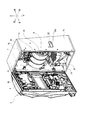
FIG. 5 is a perspective view showing the internal structure of the gaming machine 2. In FIG. 5, the front frame 8 is omitted. A harness clamp 26 is disposed on the inner surface side of the cabinet 7. The harness clamp 26 is for restricting the passage position of the wiring 27. The harness clamps 26 are disposed in the vicinity of the position where the back surface 7b and the left side surface 7a intersect on the inner surface of the cabinet 7, and the two upper and lower harness clamps 26 are fixed to the back surface 7b and the left side surface 7a. The harness clamp 26 may be fastened to the inner surface of the cabinet 7 with a screw using, for example, an attachment hole (attachment portion) shown in FIG. 5, and an adhesive or an adhesive tape is attached to the attachment surface (attachment portion). And you may attach by the adhesiveness or adhesiveness.
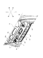
図6は、ハーネスクランプ26の拡大図である。ハーネスクランプ26は、例えば、アクリル、ポリカーボネート等の透光性を有する樹脂で形成されている。ハーネスクランプ26は、略直方体形状の外形を呈しており、その一部に大きく切り欠かれた切欠部(配線通過部)26aが形成されている。この切欠部26aに、リール装置9内に配置され、中継基板としての機能も有するリール制御基板と、電源ユニット24やホッパー20とを接続する配線27が通過するようになっている。
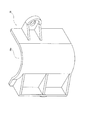
FIG. 6 is an enlarged view of the harness clamp 26. The harness clamp 26 is made of a light-transmitting resin such as acrylic or polycarbonate. The harness clamp 26 has a substantially rectangular parallelepiped outer shape, and a cutout portion (wiring passage portion) 26a that is largely cut out is formed in a part thereof. A wiring 27 that connects the power supply unit 24 and the hopper 20 to the reel control board that is disposed in the reel device 9 and also has a function as a relay board passes through the notch 26a.
配線27の通過方向に直交する直交面内において、通過する配線27の量(すなわち、その断面積)に比較して切欠部26aの断面積が大きく形成されているので、ハーネスクランプ26は配線27を締め付けずに切欠部26a内で緩く位置決めする。そして、切欠部26a内で、配線27はその配線方向(本実施形態においては、上下方向)に沿って移動することができる。なお、本実施形態においては、切欠部26aとキャビネット7の内面の一部とが協働して配線27を通過させる通過孔を形成しているが、もちろん、ハーネスクランプ26が、一部が切り欠かれた切欠部でなく周囲が閉じた配線通過孔(配線通過部)を有していてもよい。
Since the cross-sectional area of the notch 26a is formed larger than the amount of the wiring 27 that passes through (that is, the cross-sectional area) in an orthogonal plane that is orthogonal to the passing direction of the wiring 27, the harness clamp 26 is connected to the wiring 27. Is loosely positioned in the notch 26a without tightening. In the cutout portion 26a, the wiring 27 can move along the wiring direction (the vertical direction in the present embodiment). In this embodiment, the notch 26a and a part of the inner surface of the cabinet 7 cooperate to form a passage hole through which the wiring 27 passes, but of course, the harness clamp 26 is partly cut. You may have the wiring passage hole (wiring passage part) with which the circumference | surroundings were closed instead of the notch | notch part cut out.
ホッパー20のメンテナンス時に、ホッパー20がパチスロ機2手前側に引き出され、ホッパー20に接続されている配線27が引っ張られることがある。配線27自体は、メンテナンスを考慮して余裕をもった長めの配線長としていても、ハーネスクランプ26が配線27を締め付けて固定していると、配線27が移動できず、ホッパー20が充分に引き出せないという状況になってしまう。
During maintenance of the hopper 20, the hopper 20 may be pulled out toward the front side of the pachislot machine 2 and the wiring 27 connected to the hopper 20 may be pulled. Even if the wiring 27 itself has a longer wiring length with a margin in consideration of maintenance, if the harness clamp 26 fastens and fixes the wiring 27, the wiring 27 cannot move, and the hopper 20 can be pulled out sufficiently. It becomes the situation that there is not.
このハーネスクランプ26は、配線27を締め付けず、配線の上下移動を許容するので、ホッパー20のメンテナンス性を向上させる。ホッパー20を手前に引き出す際に、配線27が移動できずにホッパー20が充分に引き出せない、という事態を回避することができる。
Since the harness clamp 26 does not tighten the wiring 27 and allows the wiring to move up and down, the maintainability of the hopper 20 is improved. When the hopper 20 is pulled forward, it is possible to avoid a situation in which the wiring 27 cannot move and the hopper 20 cannot be pulled out sufficiently.
ハーネスクランプ26は、透光性を有しており、望ましくは透明である。したがって、ハーネスクランプ26の切欠部26a内にある配線27を、ハーネスクランプ26を通して視認することができる。配線27に対して不正な改造等が行われても、早期に発見することができる。ひいては、配線に対する不正行為を予防することができる。
The harness clamp 26 has translucency and is preferably transparent. Therefore, the wiring 27 in the notch 26 a of the harness clamp 26 can be visually recognized through the harness clamp 26. Even if unauthorized modification or the like is performed on the wiring 27, it can be detected at an early stage. As a result, fraudulent acts on the wiring can be prevented.
また配線27にチューブカバーなどの保護手段を施すことで断線予防や配線27の移動をさらにスムーズにさせることも可能である。
Further, by providing protective means such as a tube cover to the wiring 27, it is possible to prevent disconnection and to further smoothly move the wiring 27.
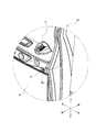
<A−3.ドアセンサの配線構造>
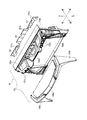
図7は、この遊技機2のドアセンサ28近傍を示す外観図である。図7においては、ドアセンサ28をキャビネット7から取り外した分解状態を示している。ドアセンサ28は、キャビネット7に対するフロント枠8の開閉状態を検出するためのセンサであって、遊技機2の右上方近傍に配置されている。より具体的には、キャビネット7の内面側における右側面7cと上面7hとが交差する位置の近傍に配置されている。
<A-3. Door sensor wiring structure>
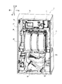
FIG. 7 is an external view showing the vicinity of the door sensor 28 of the gaming machine 2. FIG. 7 shows an exploded state in which the door sensor 28 is removed from the cabinet 7. The door sensor 28 is a sensor for detecting the open / closed state of the front frame 8 with respect to the cabinet 7, and is disposed in the vicinity of the upper right of the gaming machine 2. More specifically, the right side surface 7c and the upper surface 7h on the inner surface side of the cabinet 7 are arranged in the vicinity of the intersection.
キャビネット7内面側に取付ブラケット29が固定されている。取付ブラケット29は、キャビネット7の内周を補強するための補強フレーム30の一部であってもよく、例えば金属プレートにより構成されている。その取付ブラケット29に形成された取付孔29aに挿入され、図示しない係止フック等により係止されてドアセンサ28が取付ブラケット29に取り付けられている。
A mounting bracket 29 is fixed to the inner surface side of the cabinet 7. The mounting bracket 29 may be a part of the reinforcing frame 30 for reinforcing the inner periphery of the cabinet 7, and is constituted by, for example, a metal plate. The door sensor 28 is attached to the mounting bracket 29 by being inserted into a mounting hole 29 a formed in the mounting bracket 29 and locked by a not-shown locking hook or the like.
ドアセンサ28は、例えば、検出片28aを有するスイッチである。その検出片28aは、遊技機2の前後方向に沿って進退する。検出片28aが進出した状態(前方に突出した状態)で、ドアセンサ28はフロント枠8の開放を検出し、退避した状態(後方に押し込まれた状態)で、ドアセンサ28はフロント枠8の閉鎖を検出する。
The door sensor 28 is, for example, a switch having a detection piece 28a. The detection piece 28 a advances and retreats along the front-rear direction of the gaming machine 2. The door sensor 28 detects the opening of the front frame 8 in a state in which the detection piece 28a is advanced (a state in which the detection piece 28a protrudes forward), and the door sensor 28 closes the front frame 8 in a state of being retracted (a state in which the front frame 8 is pushed in). To detect.
ドアセンサ28とリール装置9内のリール制御基板とは、配線31により接続されている。キャビネット7の右側面7cの内面側には、遊技機外部のホールコンピュータ(不図示)からの配線を中継する外部集中端子基板36が配置されている。外部集中端子基板36は、樹脂製のベース部材37に取り付けられている。ベース部材37は透明又は半透明とされており、外部集中端子基板36の周囲を囲むように配置され、右側面7cの内面側に取り付けられている。
The door sensor 28 and the reel control board in the reel device 9 are connected by a wiring 31. On the inner surface side of the right side surface 7c of the cabinet 7, an external concentrated terminal board 36 for relaying wiring from a hall computer (not shown) outside the gaming machine is arranged. The external concentrated terminal board 36 is attached to a resin base member 37. The base member 37 is transparent or semi-transparent, is disposed so as to surround the periphery of the external concentrated terminal board 36, and is attached to the inner surface side of the right side surface 7c.
ベース部材37の一側面には、配線31を挟持可能なベースリブ37aが突出配置されている。リール制御基板からの配線31は、このベースリブ37aを通過して挟持され、ドアセンサ28へと至っている。
On one side surface of the base member 37, a base rib 37a capable of sandwiching the wiring 31 is disposed so as to protrude. The wiring 31 from the reel control board is clamped through the base rib 37 a and reaches the door sensor 28.
配線31の端部にはコネクタ32が取り付けられており、ドアセンサ28と配線31とはコネクタ接続される。このコネクタ32と配線31との接合部分は、透明または半透明な材料で構成された樹脂カバー33で周囲が覆われている。樹脂カバー33は、コネクタ32や配線31に極力密着してその内部への異物の侵入を防止すべく、可撓性を有するビニル素材が望ましい。それにより、コネクタ32、配線31又はその接合部に対する改造等の不正行為を防止することができる。
A connector 32 is attached to the end of the wiring 31, and the door sensor 28 and the wiring 31 are connected by a connector. The joint portion between the connector 32 and the wiring 31 is covered with a resin cover 33 made of a transparent or translucent material. The resin cover 33 is preferably made of a flexible vinyl material so that the resin cover 33 is in close contact with the connector 32 and the wiring 31 as much as possible to prevent foreign matter from entering the inside. Thereby, fraudulent acts such as remodeling of the connector 32, the wiring 31, or the joint portion thereof can be prevented.
樹脂カバー33は透明または半透明な材料で構成されているので、樹脂カバー33を通して内部のコネクタ32や配線31を容易に視認することができる。万一、樹脂カバー33内でコネクタ32、配線31又はその接合部に対して改造等が行われた場合でも、早期に発見することができる。ひいては、不正行為の予防に寄与する。
Since the resin cover 33 is made of a transparent or translucent material, the internal connector 32 and the wiring 31 can be easily visually recognized through the resin cover 33. In the unlikely event that the connector 32, the wiring 31, or the joint thereof is modified in the resin cover 33, it can be detected early. As a result, it contributes to prevention of fraud.
<A−4.ドアセンサの検出構造>
図8は、この遊技機2のキャビネット7とフロント枠8とを閉鎖した状態を示すドアセンサ28近傍の断面図である。図8は、遊技機2における左右方向を法線とする断面で切断している。図9は、フロント枠8を背面側の斜め上方から見た斜視図である。図9では、遊技機2の右上方近傍を示している。
<A-4. Detection structure of door sensor>
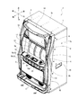
FIG. 8 is a cross-sectional view of the vicinity of the door sensor 28 showing a state in which the cabinet 7 and the front frame 8 of the gaming machine 2 are closed. FIG. 8 is cut along a cross section having the normal direction in the left-right direction in the gaming machine 2. FIG. 9 is a perspective view of the front frame 8 as viewed from obliquely upward on the back side. In FIG. 9, the upper right vicinity of the gaming machine 2 is shown.
フロント枠8の背面側における右上方近傍位置であって、ドアセンサ28に対応する位置には、受け面35aが形成されている。受け面35aは、フロント枠8の閉鎖状態において、スライド動作するドアセンサ28の検出片28aを受けて押し込むための面であって、フロント枠8側に配置されている。この遊技機2では、フロント枠8の周囲フレームを構成する金属製のフレーム部材35の一部が受け面35aとされている。フレーム部材35の一部が受け面35aとされているので、ドアセンサ28と受け面35aとの前後方向における相互の位置精度が向上している。フロント枠8の閉鎖状態におけるドアセンサ28の閉検出、開放状態におけるドアセンサ28の開検出を高い検出精度で実現することができる。
A receiving surface 35 a is formed at a position near the upper right side on the back side of the front frame 8 and corresponding to the door sensor 28. The receiving surface 35a is a surface for receiving and pushing the detection piece 28a of the sliding door sensor 28 in the closed state of the front frame 8, and is disposed on the front frame 8 side. In this gaming machine 2, a part of the metal frame member 35 that constitutes the peripheral frame of the front frame 8 is a receiving surface 35 a. Since a part of the frame member 35 is the receiving surface 35a, the positional accuracy between the door sensor 28 and the receiving surface 35a in the front-rear direction is improved. Close detection of the door sensor 28 in the closed state of the front frame 8 and open detection of the door sensor 28 in the open state can be realized with high detection accuracy.
フレーム部材35には、周壁部材34が取り付けられている。周壁部材34は、透光性を有する(望ましくは透明な)樹脂部材である。周壁部材34には、所定高さの周壁34bが立設形成されており、周壁34bが受け面35aの周囲を囲むように位置している。
A peripheral wall member 34 is attached to the frame member 35. The peripheral wall member 34 is a resin member having translucency (desirably transparent). A peripheral wall 34b having a predetermined height is erected and formed on the peripheral wall member 34, and the peripheral wall 34b is positioned so as to surround the periphery of the receiving surface 35a.
図8に示すように、キャビネット7に対してフロント枠8が閉鎖されると、ドアセンサ28の検出片28aが受け面34aに当接し、更に後方に押し込まれて退避状態となる。このとき、検出片28aの周囲は周壁34bで囲まれており、外部から検出片28aへのアクセスができないようになっている。例えば、キャビネット7とフロント枠8との隙間から不正工具を挿入し、検出片28aに不正アクセスして検出片28aが常に押し込まれている状態(すなわちフロント枠8を開いても遊技機2はフロント枠8が閉じていると認識している状態)にさせようとしても、周壁34bの存在により不正工具の検出片28aへの到達は非常に困難とされている。周壁34bは、受け面34aの全周を囲むように立設形成されることが望ましい。ただし、全周でなくても、キャビネット7とフロント枠8との隙間からの不正アクセスを防止すべく、遊技機2の右側面側から上面側にかけて立設されていれば、一定の不正防止効果を発揮することができる。
As shown in FIG. 8, when the front frame 8 is closed with respect to the cabinet 7, the detection piece 28 a of the door sensor 28 comes into contact with the receiving surface 34 a and is further pushed backward to be in a retracted state. At this time, the periphery of the detection piece 28a is surrounded by a peripheral wall 34b so that the detection piece 28a cannot be accessed from the outside. For example, an unauthorized tool is inserted through the gap between the cabinet 7 and the front frame 8 to illegally access the detection piece 28a so that the detection piece 28a is always pushed in (that is, the gaming machine 2 remains in the front even if the front frame 8 is opened). Even when the frame 8 is recognized as being closed, it is very difficult for the unauthorized tool to reach the detection piece 28a due to the presence of the peripheral wall 34b. The peripheral wall 34b is preferably erected so as to surround the entire periphery of the receiving surface 34a. However, even if it is not all around, if it is erected from the right side surface to the top surface side of the gaming machine 2 in order to prevent unauthorized access from the gap between the cabinet 7 and the front frame 8, a certain fraud prevention effect Can be demonstrated.
<B−1.リール装置>
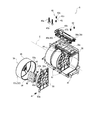
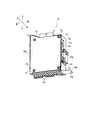
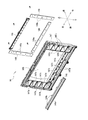
図10は、この遊技機2のキャビネット7内部に配置されるリール装置9の分解斜視図である。リール装置9は、リールユニットベース38、リール11〜13、リール制御基板39、リールランプ基板40を有して大略構成される。なお、図10においては、リール13、リール制御基板39、リールランプ基板40が分解表示されている。
<B-1. Reel device>
FIG. 10 is an exploded perspective view of the reel device 9 disposed inside the cabinet 7 of the gaming machine 2. The reel device 9 includes a reel unit base 38, reels 11 to 13, a reel control board 39, and a reel lamp board 40. In FIG. 10, the reel 13, the reel control board 39, and the reel lamp board 40 are disassembled and displayed.
リールユニットベース38は、前面が開口された中空構造のユニットであって、樹脂材料で形成されている。その中空内部に3つのリール11〜13を保持しており、リール11〜13が、透明板8aを介して遊技機2の前方側から視認できるようになっている。
The reel unit base 38 is a hollow unit having an open front surface, and is formed of a resin material. Three reels 11 to 13 are held inside the hollow, and the reels 11 to 13 are visible from the front side of the gaming machine 2 through the transparent plate 8a.
リールユニットベース38は、キャビネット7内部に固定されたリールブラケット41(図5参照)に載置されて取り付けられている。リール装置9の後面側では、リールユニットベース38後面側下方に突出形成された突起部(不図示)が、リールブラケット41に開口形成された取付孔に挿入されることによって取り付けられている。リール装置9の前面側では、着脱可能な樹脂製のリベット42によって、リールユニットベース38の前面側下方がリールブラケット41に取り付けられている。なお、リベット42は、リールユニットベース38の前面側下方においてリール11〜13、リールユニットベース38、リールブラケット41を共締めしている。
The reel unit base 38 is placed and attached to a reel bracket 41 (see FIG. 5) fixed inside the cabinet 7. On the rear surface side of the reel device 9, a protrusion (not shown) formed to protrude downward on the rear surface side of the reel unit base 38 is attached by being inserted into an attachment hole formed in the reel bracket 41. On the front side of the reel device 9, a lower part on the front side of the reel unit base 38 is attached to the reel bracket 41 by a detachable resin rivet 42. The rivet 42 is fastened together with the reels 11 to 13, the reel unit base 38, and the reel bracket 41 at the lower front side of the reel unit base 38.
リールユニットベース38の上面38aには、リール制御基板39とリールランプ基板40とが取り付けられている。リール制御基板39、リールランプ基板40は、各々透明な基板ケース39a、40aに収納され保護されている。基板ケース39a,40aが透明であるので、基板ケース39a,40aを介して外部からリール制御基板39、リールランプ基板40を容易に視認することができる。したがって、これらの基板39,40に対して改造等の不正行為が行われた場合であっても、容易に早期発見をすることができる。
A reel control board 39 and a reel lamp board 40 are attached to the upper surface 38 a of the reel unit base 38. The reel control board 39 and the reel lamp board 40 are housed and protected in transparent board cases 39a and 40a, respectively. Since the substrate cases 39a and 40a are transparent, the reel control substrate 39 and the reel lamp substrate 40 can be easily visually recognized from the outside through the substrate cases 39a and 40a. Therefore, even if an illegal act such as remodeling is performed on these substrates 39 and 40, early detection can be easily performed.
基板ケース39a,40aは、各々2箇所で着脱可能な樹脂製のリベット43によって上面38aに取り付けられている。樹脂製のリベット43は、基板ケース39a,40aに形成された取付孔と上面38aに形成された取付孔とに挿入し、更に頂部43aを押し込むと底部43bが放射方向に拡張して抜けなくなって取付けが完了するようになっている。取付け状態において頂部43aを引き抜くと底部43bが収縮して取外しができるようになっている。
The substrate cases 39a and 40a are attached to the upper surface 38a by resin rivets 43 that can be attached and detached at two locations. The resin rivet 43 is inserted into the mounting holes formed in the substrate cases 39a and 40a and the mounting holes formed in the upper surface 38a. When the top 43a is further pushed in, the bottom 43b expands in the radial direction and cannot be removed. Installation is completed. When the top 43a is pulled out in the attached state, the bottom 43b contracts and can be removed.
リベット43によって、基板ケース39a,40aは上面38aに対して簡単に着脱可能な構造となっている。基板ケース39a、40aを簡単に取り外すことができるので、リール制御基板39やリールランプ基板40の裏面側(下面側)を確認する作業も容易となっている。基板39,40の裏面側に対し不正な改造等が行われた場合であっても、基板ケース39a,40aの取外しにより早期発見をすることができる。なお、リベット43の着脱構造は、リベット42や後述するリベット44においても共通である。
By the rivets 43, the substrate cases 39a and 40a can be easily attached to and detached from the upper surface 38a. Since the substrate cases 39a and 40a can be easily removed, it is easy to check the back side (lower surface side) of the reel control board 39 and the reel lamp board 40. Even if unauthorized modification or the like is performed on the back side of the substrates 39 and 40, early detection can be performed by removing the substrate cases 39a and 40a. The attachment / detachment structure of the rivet 43 is common to the rivet 42 and the rivet 44 described later.
リール制御基板39は、内部にリール11〜13を回転駆動する駆動モータのドライバ回路を有している。リール制御基板39は、遊技機2の全体動作を制御するメイン基板(主制御基板)45(図3参照)と接続されており、メイン基板45からの動作制御コマンドに基づいて、リール装置9の動作(駆動モータの回転動作)を制御する。
The reel control board 39 has a driver circuit for a drive motor that rotationally drives the reels 11 to 13 inside. The reel control board 39 is connected to a main board (main control board) 45 (see FIG. 3) that controls the entire operation of the gaming machine 2, and based on an operation control command from the main board 45, the reel control board 39 Controls the operation (rotation operation of the drive motor).
リール制御基板39には、キャビネット7の下方に配置された電源ユニット24からの配線46aがコネクタ46bによって接続されている。また、電源ユニット24の近傍に位置するホッパー20からの配線47aがコネクタ47bによって接続されている。これにより、電源ユニット24からの電力が、リール制御基板39を介してホッパー20に供給されるようになっており、リール制御基板39は、電源供給における中継基板としての機能を発揮している。電源ユニット24からの電力は、リール制御基板39を介してメイン制御基板45へも供給されている。
The reel control board 39 is connected to a wiring 46a from the power supply unit 24 disposed below the cabinet 7 by a connector 46b. Further, a wire 47a from the hopper 20 located in the vicinity of the power supply unit 24 is connected by a connector 47b. Thus, power from the power supply unit 24 is supplied to the hopper 20 via the reel control board 39, and the reel control board 39 exhibits a function as a relay board in power supply. Power from the power supply unit 24 is also supplied to the main control board 45 via the reel control board 39.
リールランプ基板40は、各リール11〜13内に配置されたバックランプ48の点灯及び消灯に用いるための中継基板である。リールランプ基板40は、各リール11〜13内のバックランプ48に接続され、かつ、遊技機2の各種演出制御を実行するサブ基板(演出制御基板)49(図3参照)にも接続されており、サブ基板49からの演出制御コマンドに基づくバックランプ48の点灯・消灯を実現する。
The reel lamp substrate 40 is a relay substrate used for turning on and off the back lamps 48 disposed in the reels 11 to 13. The reel lamp board 40 is connected to a back lamp 48 in each reel 11 to 13 and also connected to a sub board (effect control board) 49 (see FIG. 3) for executing various effect controls of the gaming machine 2. Thus, the back lamp 48 is turned on / off based on the effect control command from the sub-board 49.
リール11〜13は、遊技者に呈示する図柄を回転・停止させるためのものである。リール11〜13は、リールユニットベース38の中空内部に、リベット43,44によって着脱可能に取り付けられている。容易に脱着できるリベット43,44によってリール11〜13がリールユニットベース38に取り付けられているので、メンテナンス等の際の取外しが容易である。リール11〜13は、左右方向に並んで配列されている。左右方向に延びる回転軸Xを同軸として、3つのリール11〜13におけるリールテープユニット54が回転可能とされている。
The reels 11 to 13 are for rotating and stopping symbols to be presented to the player. The reels 11 to 13 are detachably attached to the hollow interior of the reel unit base 38 by rivets 43 and 44. Since the reels 11 to 13 are attached to the reel unit base 38 by the rivets 43 and 44 that can be easily attached and detached, it is easy to remove at the time of maintenance or the like. The reels 11 to 13 are arranged side by side in the left-right direction. The reel tape unit 54 in the three reels 11 to 13 is rotatable with the rotation axis X extending in the left-right direction being coaxial.
図10においては、リール11〜13のうち、リール13のみを前方に分解図示している。3つのリール11〜13は、略同様の構造を有しているので、以下、リール13についてのみ説明し、リール11,12についての説明を省略する。図11及び図12は、リール13の分解斜視図である。図10は、リール13全体を右斜め上方から見た図であり、図11は、リールテープユニット54を省略してリール13を左斜め後方(駆動モータ51側)から見た図である。
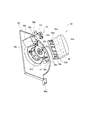
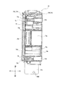
In FIG. 10, among the reels 11 to 13, only the reel 13 is shown in an exploded view forward. Since the three reels 11 to 13 have substantially the same structure, only the reel 13 will be described below, and the description of the reels 11 and 12 will be omitted. 11 and 12 are exploded perspective views of the reel 13. FIG. 10 is a view of the entire reel 13 as viewed from the diagonally upper right side, and FIG. 11 is a diagram of the reel 13 viewed from the diagonally left rear side (drive motor 51 side) with the reel tape unit 54 omitted.
リール13は、リールベース50、駆動モータ51、回転センサ52、バックランプユニット53、リールテープユニット54を有して大略構成されている。リールベース50は、リール13をリールユニットベース38に取り付けるためのベース部材であり、樹脂製の略平板状部材である。リールベース50の上下2箇所には取付孔50aが開口形成されており、この取付孔50aにリベット43,44を貫通させてリールベース50が前方からリールユニットベース38の中空内部に取り付けられる。
The reel 13 has a reel base 50, a drive motor 51, a rotation sensor 52, a back lamp unit 53, and a reel tape unit 54, and is generally configured. The reel base 50 is a base member for attaching the reel 13 to the reel unit base 38, and is a substantially flat plate member made of resin. Mounting holes 50a are formed at two locations on the upper and lower sides of the reel base 50, and the reel base 50 is attached to the hollow interior of the reel unit base 38 from the front through the mounting holes 50a through the rivets 43 and 44.
リールベース50には、駆動モータ51、回転センサ52、バックランプユニット53が取り付けられている。駆動モータ51は、リールテープユニット54を回転駆動するためのモータである。
A drive motor 51, a rotation sensor 52, and a back lamp unit 53 are attached to the reel base 50. The drive motor 51 is a motor for driving the reel tape unit 54 to rotate.
この遊技機2においては駆動モータ51として、バイポーラ型のステッピングモータが用いられている。バイポーラ型のステッピングモータを用いることにより、高い駆動トルク、円滑な回転、高い停止位置精度、確実な停止保持等の機能を実現している。リールテープユニット54の停止時に発生する駆動モータ(バイポーラ型ステッピングモータ)51内のスイッチ切替動作に対して一旦励磁をかけることで貫通電流を防止している。それにより、スムーズなリール停止動作とモータ破損の防止とを実現している。
In the gaming machine 2, a bipolar stepping motor is used as the drive motor 51. By using a bipolar stepping motor, functions such as high drive torque, smooth rotation, high stop position accuracy, and reliable stop and hold are realized. A through current is prevented by applying excitation to the switch switching operation in the drive motor (bipolar stepping motor) 51 that occurs when the reel tape unit 54 is stopped. As a result, a smooth reel stop operation and prevention of motor damage are realized.
駆動モータ51のモータ軸51aには、リールテープユニット54がキー及びキー溝を用いて固定取付けされており、リールテープユニット54は、モータ軸51aと同期回転するようになっている。リールテープユニット54は、取付けリング55、補助リング56、リールテープ57を有している。
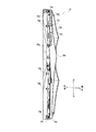
A reel tape unit 54 is fixedly attached to the motor shaft 51a of the drive motor 51 using a key and a key groove, and the reel tape unit 54 rotates synchronously with the motor shaft 51a. The reel tape unit 54 includes a mounting ring 55, an auxiliary ring 56, and a reel tape 57.
取付けリング55は、モータ軸51aに取り付けるためのリング部材であって、回転中心近傍に位置する取付部55aから放射状に延びる複数の支持部55bが、円環部55cを保持するように構成されている。取付部55aには、モータ軸51aを貫通させる貫通孔とモータ軸51a側のキーを挿入するためのキー溝55fとが形成されている。
The attachment ring 55 is a ring member for attachment to the motor shaft 51a, and a plurality of support portions 55b extending radially from the attachment portion 55a located in the vicinity of the rotation center are configured to hold the annular portion 55c. Yes. The attachment portion 55a is formed with a through hole through which the motor shaft 51a passes and a key groove 55f for inserting a key on the motor shaft 51a side.
円環部55cには、その外周面に沿ってリールテープ57が貼付される。リールテープ57は、展開すると縦長の長方形状を呈する透明又は半透明のフィルムであって、その周面57aには、複数の装飾図柄が配列されている。装飾図柄は、例えば、「7」や「チェリー」や「ベル」を示す図柄である。3つのリール11〜13が遊技者に向けて停止表示した装飾図柄の組合せによって、当たり/外れが決定されるようになっている。
A reel tape 57 is attached to the annular portion 55c along the outer peripheral surface thereof. The reel tape 57 is a transparent or translucent film that has a vertically long rectangular shape when unfolded, and a plurality of decorative symbols are arranged on its peripheral surface 57a. The decorative symbol is, for example, a symbol indicating “7”, “cherry”, or “bell”. Whether the three reels 11 to 13 are stopped or displayed toward the player is determined based on the combination of decorative symbols.
円環部55cの外周面に沿うように、リールテープ57が円環状に貼付される。リールテープ57の長辺の長さは、円環部55cの外周面の周長と略一致している。円環部55cは、リールテープ57の左側辺側に貼付される。円環部55cの外周面には、図11に部分拡大図を示すように、基準マーク55dが刻印されている。基準マーク55dは、例えば、左右方向に沿った3つの線で表現されたマークである。リールテープ57を貼付する際、その先端位置(後端位置も略同一である)を基準マーク55dの位置に合わせて貼付する。
The reel tape 57 is affixed in an annular shape along the outer peripheral surface of the annular portion 55c. The length of the long side of the reel tape 57 substantially coincides with the peripheral length of the outer peripheral surface of the annular portion 55c. The annular portion 55 c is attached to the left side of the reel tape 57. A reference mark 55d is engraved on the outer peripheral surface of the annular portion 55c as shown in a partially enlarged view in FIG. The reference mark 55d is, for example, a mark expressed by three lines along the left-right direction. When affixing the reel tape 57, the front end position (the rear end position is also substantially the same) is aligned with the position of the reference mark 55d.
取付けリング55の支持部55bには、回転センサ52によって検出するための検出片55eが突出形成されている。検出片55eは、取付けリング55の1回転で回転センサ52により1回検出されるようになっている。検出片55eと基準マーク55dとの位置関係が予め分かっているので、駆動モータ51を回転駆動したときに、リールテープ57の先端位置がどこにあるかを把握することができる。したがって、検出片55e、基準マーク55dの位置に基づいて、正確に所望の装飾図柄を停止表示することができる。
A detection piece 55 e for detection by the rotation sensor 52 is formed on the support portion 55 b of the attachment ring 55 so as to protrude. The detection piece 55e is detected once by the rotation sensor 52 by one rotation of the mounting ring 55. Since the positional relationship between the detection piece 55e and the reference mark 55d is known in advance, when the drive motor 51 is driven to rotate, it is possible to grasp where the tip position of the reel tape 57 is. Therefore, a desired decorative design can be accurately stopped and displayed based on the positions of the detection piece 55e and the reference mark 55d.
回転センサ52は、図12に示すように、リールベース50の左側面側に突出形成された膨出部50b上に取り付けられている。膨出部50bには複数の取付孔50cが形成され、回転センサ52には、その取付孔50cに対応する位置に複数の取付フック52aが形成されている。取付フック52aを取付孔50cに係止することにより、簡単に回転センサ52を膨出部50bにワンタッチで取り付けることができる。また、取付フック52aは、簡単に解除可能とされているので、メンテナンス時等においては、回転センサ52を膨出部50bからワンタッチで取り外すことができる。
As shown in FIG. 12, the rotation sensor 52 is mounted on a bulging portion 50 b that is formed to protrude from the left side surface of the reel base 50. A plurality of attachment holes 50c are formed in the bulging portion 50b, and a plurality of attachment hooks 52a are formed in the rotation sensor 52 at positions corresponding to the attachment holes 50c. By locking the attachment hook 52a in the attachment hole 50c, the rotation sensor 52 can be easily attached to the bulging portion 50b with one touch. Moreover, since the attachment hook 52a can be easily released, the rotation sensor 52 can be detached from the bulging portion 50b with a single touch during maintenance or the like.
なお、基準マーク55dは、取付けリング55にのみ刻印されており、対面側の補助リング56には刻印されていない。検出片55eが形成された取付けリング55に基準マーク55dが一体的に刻印されているので、検出片55eと基準マーク55dとの高い位置精度、ひいては、検出片55eとリールテープ57先端との高い位置精度が実現され、装飾図柄の停止位置精度の向上に寄与している。
The reference mark 55d is stamped only on the attachment ring 55, and is not stamped on the auxiliary ring 56 on the facing side. Since the reference mark 55d is integrally engraved on the mounting ring 55 on which the detection piece 55e is formed, high positional accuracy between the detection piece 55e and the reference mark 55d, and consequently, the detection piece 55e and the tip of the reel tape 57 are high. Position accuracy is realized, which contributes to improvement of the stop position accuracy of decorative symbols.
リールテープ57の右側辺側には、補助リング56の円環部56aが貼付されている。補助リング56は、取付けリング55と共にリールテープ57を保持するための部材であるが、補助リング56には、取付部55aや支持部55bに相当する部分がなく、円環形状の円環部56aのみで構成されている。したがって、補助リング56は、貼付されたリールテープ57の回転によって連れ回りすることとなる。取付部55aや支持部55bに相当する部分がなく、簡易な構成とされているので、補助リング56を軽量かつ低コストに構成することができる。
An annular portion 56 a of the auxiliary ring 56 is attached to the right side of the reel tape 57. The auxiliary ring 56 is a member for holding the reel tape 57 together with the attachment ring 55. However, the auxiliary ring 56 has no portion corresponding to the attachment portion 55a or the support portion 55b, and an annular ring portion 56a. It consists only of. Therefore, the auxiliary ring 56 is rotated by the rotation of the stuck reel tape 57. Since there is no portion corresponding to the attachment portion 55a and the support portion 55b and it has a simple configuration, the auxiliary ring 56 can be configured to be lightweight and low cost.
リールベース50の左側面には、バックランプユニット53が取り付けられている。バックランプユニット53は、リールテープ57の円環内部であって、遊技者に呈示する装飾図柄の後方に位置するように配置され、リールテープ57上の装飾図柄を後方から照明する。バックランプユニット53の前面側は、隔壁53aにより複数(例えば、6個)の隔室に分割され、各隔室内に各々バックランプ48が配置されている。バックランプ48は、例えばLEDである。各リール11〜13のバックランプ48は、配線によりリールランプ基板40に接続されている。
A back lamp unit 53 is attached to the left side surface of the reel base 50. The back lamp unit 53 is disposed inside the ring of the reel tape 57 and positioned behind the decorative design presented to the player, and illuminates the decorative design on the reel tape 57 from the rear. The front side of the back lamp unit 53 is divided into a plurality of (for example, six) compartments by a partition wall 53a, and a back lamp 48 is disposed in each compartment. The back lamp 48 is, for example, an LED. The back lamps 48 of the reels 11 to 13 are connected to the reel lamp substrate 40 by wiring.
図12に示すように、バックランプユニット53の右側部は、取付部53bとされ、その取付部53bに複数の取付孔53cが開口形成されている。リールベース50の左側面には、取付孔53cに対応する位置に取付フック50dが形成されている。この取付フック50dを取付孔53cに係止することにより、簡単にバックランプユニット53をリールベース50にワンタッチで取り付けることができる。このとき、リールベース50の左側面に突出形成された位置決めピン50eが取付部53bに開口形成された位置決め孔53dに挿入され、バックランプユニット53の位置精度向上が図られている。また、回転センサ52と同様に、取付フック50dは、簡単に解除可能とされているので、メンテナンス時等においては、バックランプユニット53をリールベース50からワンタッチで取り外すことができる。
As shown in FIG. 12, the right side portion of the back lamp unit 53 is an attachment portion 53b, and a plurality of attachment holes 53c are formed in the attachment portion 53b. A mounting hook 50d is formed on the left side surface of the reel base 50 at a position corresponding to the mounting hole 53c. By locking the mounting hook 50d in the mounting hole 53c, the back lamp unit 53 can be easily mounted on the reel base 50 with one touch. At this time, a positioning pin 50e formed to project from the left side surface of the reel base 50 is inserted into a positioning hole 53d formed in the attachment portion 53b so that the positional accuracy of the back lamp unit 53 is improved. Similarly to the rotation sensor 52, the attachment hook 50d can be easily released, so that the back lamp unit 53 can be detached from the reel base 50 with a single touch during maintenance or the like.
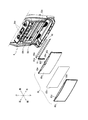
<C−1.補助金庫>
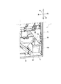
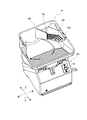
図13は、この遊技機2の補助金庫58近傍を拡大して示す部分拡大図である。補助金庫58は、ホッパー20から溢れたメダルを受け入れて貯留するための箱状部材である。補助金庫58は、キャビネット7内部の、遊技機2の右下方近傍であって、ホッパー20の右方に隣接して配置され、キャビネット7の底板7j上に載置されている。
<C-1. Auxiliary safe>
FIG. 13 is a partially enlarged view showing the vicinity of the auxiliary safe 58 of the gaming machine 2 in an enlarged manner. The auxiliary safe 58 is a box-shaped member for receiving and storing medals overflowing from the hopper 20. The auxiliary safe 58 is disposed in the cabinet 7 near the lower right side of the gaming machine 2 and adjacent to the right side of the hopper 20, and is placed on the bottom plate 7 j of the cabinet 7.
補助金庫58は、ホッパー20の漏出口20a(図5参照)から溢れたメダルを上面開口58aから箱部材58b内部に受け入れて貯留する。図14は、補助金庫58を左斜め上方から見た斜視図である。筐体58bは、略四角筒形状を呈する樹脂部材であって、周囲四方を囲むような形状とされている。上面開口58aと共に、底面側にも排出開口58cが大きく開口形成されている。
The auxiliary safe 58 receives and stores medals overflowing from the leak outlet 20a (see FIG. 5) of the hopper 20 into the box member 58b from the upper surface opening 58a. FIG. 14 is a perspective view of the auxiliary safe 58 as viewed from the upper left. The housing 58b is a resin member having a substantially square cylindrical shape, and has a shape surrounding the surrounding four sides. Along with the top surface opening 58a, a large discharge opening 58c is formed on the bottom surface side.
排出開口58cは、遊技機ホールの島設備がメダルの自動回収システムを有する場合に使用するための開口である。島設備側のメダル回収経路に向けて、排出開口58cからメダルが落下するようになっている。その場合は、キャビネット7の底板7jにも、排出開口58cに対応する位置にメダル落下のための開口(不図示)が形成される。
The discharge opening 58c is an opening for use when the island facility of the gaming machine hall has an automatic medal collection system. The medal is dropped from the discharge opening 58c toward the medal collection path on the island facility side. In that case, an opening (not shown) for dropping a medal is also formed in the bottom plate 7j of the cabinet 7 at a position corresponding to the discharge opening 58c.
島設備がメダル自動回収システムを有さない場合は、排出開口58cが複数(この遊技機2においては、3枚)の底板58dによって閉鎖される。底板58dは、例えば、アルミ又はステンレス等の金属板である。3枚の底板58dによって排出開口58cを閉鎖するので、上面開口58aから受け入れたメダルは、下方に排出されず、補助金庫58内に貯留される。
When the island facility does not have an automatic medal collection system, the discharge opening 58c is closed by a plurality of (three in this gaming machine 2) bottom plate 58d. The bottom plate 58d is, for example, a metal plate such as aluminum or stainless steel. Since the discharge opening 58 c is closed by the three bottom plates 58 d, medals received from the upper surface opening 58 a are not discharged downward but are stored in the auxiliary safe 58.
筐体58bの底面近傍には、各底板58dに対応してフック58eが形成され、底板58dを係止するようになっている。底板58dは、フック58eに係止されることにより、容易に筐体58bの底面から脱落しないようになっている。
In the vicinity of the bottom surface of the housing 58b, hooks 58e are formed corresponding to the respective bottom plates 58d so as to lock the bottom plate 58d. The bottom plate 58d is locked to the hook 58e so that it does not easily fall off the bottom surface of the housing 58b.
なお、排出開口58cを使用する場合は、フック58eを解除して底板58dを筐体58bの底面から取り外す。図14に示すように、筐体58bの、例えば左外側面58fに、取り外した3枚の底板58dを収納するための収納部58gが設けられていてもよい。3枚の底板58dを収納部58gに収納することができるので、底板58dの紛失防止に寄与する。
When the discharge opening 58c is used, the hook 58e is released and the bottom plate 58d is removed from the bottom surface of the housing 58b. As shown in FIG. 14, a housing 58g for housing the removed three bottom plates 58d may be provided, for example, on the left outer surface 58f of the housing 58b. Since the three bottom plates 58d can be stored in the storage portion 58g, it contributes to the prevention of the loss of the bottom plate 58d.
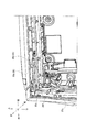
<D−1.メイン基板>
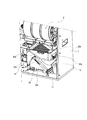
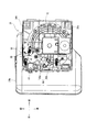
図15は、この遊技機2のメイン基板(主制御基板)45近傍を拡大して示す部分拡大図である。メイン基板45は、この遊技機2の全体の動作を制御するための電子回路基板である。
<D-1. Main board>
FIG. 15 is a partially enlarged view showing the vicinity of the main board (main control board) 45 of the gaming machine 2 in an enlarged manner. The main board 45 is an electronic circuit board for controlling the overall operation of the gaming machine 2.
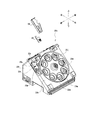
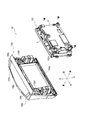
キャビネット7内部の上面7hに近い位置において、キャビネット7の背面7bにメイン基板ユニット59が取り付けられている。図16は、メイン基板ユニット59の概略構成を示す分解斜視図である。図17は、メイン基板ユニット59の正面図である。メイン基板ユニット59は、取付ベース60、基板ケース61、メイン基板45、スイッチボックス62を有して大略構成される。基板ケース61は、本体ケース61aと蓋ケース61bとを有して構成され、本体ケース61aと蓋ケース61bとにメイン基板45が収容されるようになっている。
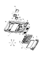
A main board unit 59 is attached to the back surface 7 b of the cabinet 7 at a position close to the top surface 7 h inside the cabinet 7. FIG. 16 is an exploded perspective view showing a schematic configuration of the main board unit 59. FIG. 17 is a front view of the main board unit 59. The main board unit 59 has a mounting base 60, a board case 61, a main board 45, and a switch box 62 and is generally configured. The substrate case 61 includes a main body case 61a and a lid case 61b, and the main substrate 45 is accommodated in the main body case 61a and the lid case 61b.
取付ベース60は、基板ケース61を背面7bに取り付けるための大略盤状とされた部材である。取付ベース60は、透明又は半透明の樹脂材料で形成され、基板ケース61を保持する保持面(基板ケース保持面)60a、スイッチボックス62を受け入れる保持面(スイッチボックス保持面)60bとを有している。
The mounting base 60 is a substantially board-shaped member for mounting the substrate case 61 to the back surface 7b. The mounting base 60 is made of a transparent or translucent resin material and has a holding surface (substrate case holding surface) 60a for holding the substrate case 61 and a holding surface (switch box holding surface) 60b for receiving the switch box 62. ing.
保持面60aには、基板ケース61を保持した際に基板ケース61によって覆われる位置に、取付ベース60を背面7bにネジで取り付けるための取付孔60cが形成されている。保持面60aに保持した基板ケース61を係止する係止フック60dが保持面60a近傍に配置されている。保持面60bの近傍にも、保持面60bに保持したスイッチボックス62を係止する係止フック60gが配置されている。
The holding surface 60a is formed with a mounting hole 60c for mounting the mounting base 60 to the back surface 7b with a screw at a position covered by the substrate case 61 when the substrate case 61 is held. A locking hook 60d that locks the substrate case 61 held on the holding surface 60a is disposed in the vicinity of the holding surface 60a. A locking hook 60g for locking the switch box 62 held on the holding surface 60b is also arranged in the vicinity of the holding surface 60b.
保持面60aには、本体カシメ部60eが2箇所配置されている。この本体カシメ部60eにカシメ部材60fが挿入されて、基板ケース61が保持面60aに保持されると、基板ケース61側の本体カシメ部と係合され、保持面60aからの基板ケース61の取外しが実質的に不可能とされる(又は、取り外した際に、一部が破壊されてその痕跡が残存する)。
Two main body caulking portions 60e are arranged on the holding surface 60a. When the caulking member 60f is inserted into the main body caulking portion 60e and the substrate case 61 is held on the holding surface 60a, the main body caulking portion on the substrate case 61 side is engaged, and the substrate case 61 is removed from the holding surface 60a. Is practically impossible (or, when removed, part of it is destroyed and its trace remains).
基板ケース61は、本体ケース61aと蓋ケース61bとが回転軸部61cを中心に回転することにより開閉可能に構成されている。本体ケース61a及び蓋ケース61bは、共に透明又は半透明の樹脂材料で形成されており、内部に収容するメイン基板45が基板ケース61外部から容易に視認可能となっている。したがって、メイン基板45への改造等の不正行為の早期発見に寄与している。
The substrate case 61 is configured to be openable and closable when the main body case 61a and the lid case 61b rotate about the rotation shaft portion 61c. Both the main body case 61a and the lid case 61b are made of a transparent or translucent resin material, and the main substrate 45 accommodated therein can be easily visually recognized from the outside of the substrate case 61. Therefore, it contributes to early detection of fraudulent acts such as modifications to the main board 45.
本体ケース61aには、取付ベース60の本体カシメ部60eと係合される本体カシメ部61dが本体カシメ部60eに対応する位置に2箇所配置されている。その結果、基板ケース61と取付ベース60とを2回カシメることが可能となっている。その結果、1箇所の本体カシメ部(60e,61d)を破壊して基板ケース61を取付ベース60から1回取り外しても、もう1箇所の本体カシメ部(60e,61d)によって基板ケース61を取付ベース60にカシメることができる。
In the main body case 61a, two main body caulking portions 61d that are engaged with the main body caulking portion 60e of the mounting base 60 are disposed at positions corresponding to the main body caulking portion 60e. As a result, the board case 61 and the mounting base 60 can be crimped twice. As a result, even if the main body crimping portion (60e, 61d) is broken and the substrate case 61 is removed from the mounting base 60 once, the substrate case 61 is attached by the other main body crimping portion (60e, 61d). The base 60 can be caulked.
本体ケース61aと蓋ケース61bとは、ケースカシメ部61fによって相互にカシメ係合されるようになっている。ケースカシメ部61fを破壊しないと本体ケース61aと蓋ケース61bとを開放することができないようになっているので、メイン基板45に不正アクセスした場合にその痕跡が確実に残存するようになっている。
The main body case 61a and the lid case 61b are caulked and engaged with each other by a case caulking portion 61f. Since the main body case 61a and the lid case 61b cannot be opened unless the case caulking portion 61f is destroyed, the trace remains reliably when the main board 45 is illegally accessed. .
また、本体ケース61aと蓋ケース61bとには、シール貼付面61eが形成されている。本体ケース61a側のシール貼付面61eと蓋ケース61b側のシール貼付面61eとは、両ケース61a,61bが閉鎖した状態で面一となるように形成され、この閉鎖状態で両ケースのシール貼付面61eに跨るように封印シール(不図示)が貼付されるようになっている。
Further, a seal sticking surface 61e is formed on the main body case 61a and the lid case 61b. The seal sticking surface 61e on the main body case 61a side and the seal sticking surface 61e on the lid case 61b side are formed so as to be flush with each other when the cases 61a and 61b are closed. A seal seal (not shown) is attached so as to straddle the surface 61e.
更に、そのシール貼付面61eを覆うように、封印カバー61gが取り付けられるようになっている。封印カバー61gは、封印シールを保護するためのもので、不用意な封印シールの破損を防止する。封印カバー61gは透明又は半透明の樹脂材料で形成され、取付状態で、外部から封印シールの破損状態が視認可能となっている。
Further, a sealing cover 61g is attached so as to cover the sticking surface 61e. The seal cover 61g is for protecting the seal seal, and prevents the seal seal from being accidentally damaged. The sealing cover 61g is formed of a transparent or translucent resin material, and in a mounted state, the damaged state of the sealing seal can be visually recognized from the outside.
本体ケース61aと蓋ケース61bとを解放する際には、封印カバー61gを取外し、封印シールを破損する必要がある。そのため、封印シールの破損状態を確認すれば、本体ケース61aと蓋ケース61bとが開放されたか否か、すなわち、メイン基板45への不正アクセスがあったか否かを容易に確認することができる。
When releasing the main body case 61a and the lid case 61b, it is necessary to remove the sealing cover 61g and break the sealing seal. Therefore, if the broken state of the seal seal is confirmed, it can be easily confirmed whether or not the main body case 61a and the lid case 61b are opened, that is, whether or not there is an unauthorized access to the main board 45.
なお、封印シールは、所定の情報部を有することが望ましい。その情報部には、遊技機2やメイン基板45等の管理番号等の情報が含まれていてもよい。情報部は、例えば、封印シールに印刷されたバーコード等であってもよいが、RFID等のICを用いた情報記憶装置が封印シール内に埋めこまれていてもよい。
The seal seal desirably has a predetermined information part. The information portion may include information such as a management number of the gaming machine 2 and the main board 45. The information unit may be, for example, a barcode printed on a seal sticker, or an information storage device using an IC such as an RFID may be embedded in the seal sticker.
メイン基板45は、この遊技機2の全体動作を制御するための電子回路基板であって、電源ユニット24、サブ制御基板49、リール制御基板39等と配線接続されている。メイン基板45の表面には、打止有無スイッチ45aや、遊技機2の遊技状態(例えば、パチスロ機における当選確率を設定する設定値)を設定するための設定値表示LED45b等が実装されている。打止有無スイッチ45aは、所定の契機に基づき打止を発生させるか否かを設定するためのスイッチである。設定値表示LED45bは、後述する設定値変更処理時に、遊技機2の設定値(例えば、“1”〜“6”)を表示するための表示器である。
The main board 45 is an electronic circuit board for controlling the overall operation of the gaming machine 2, and is connected to the power supply unit 24, the sub control board 49, the reel control board 39, and the like. On the surface of the main board 45, a stop presence / absence switch 45a, a setting value display LED 45b for setting a gaming state of the gaming machine 2 (for example, a setting value for setting a winning probability in a pachislot machine), and the like are mounted. . The stop presence / absence switch 45a is a switch for setting whether or not to generate a stop based on a predetermined trigger. The set value display LED 45b is a display for displaying set values (for example, “1” to “6”) of the gaming machine 2 during a set value change process described later.
メイン基板45には、メイン基板45の型番等の文字情報45cが表示されている。この文字情報45cは、エッチング処理等によって作成されてもよいが、この遊技機2においては、文字情報45cはレーザーマーキングによって刻印されている。
On the main board 45, character information 45c such as a model number of the main board 45 is displayed. The character information 45c may be created by etching or the like, but in the gaming machine 2, the character information 45c is imprinted by laser marking.
スイッチボックス62は、略直方体形状のスイッチユニットである。スイッチボックス62は、前面に開閉ドア62aを有しており、内部のスイッチ等が不用意に押されてしまうのを防止している。その開閉ドア62aの開閉状態は、開閉センサ62bによって検出されるようになっている。
The switch box 62 is a switch unit having a substantially rectangular parallelepiped shape. The switch box 62 has an open / close door 62a on the front surface to prevent an internal switch or the like from being inadvertently pressed. The open / close state of the open / close door 62a is detected by an open / close sensor 62b.
スイッチボックス62は、設定値変更キー62cとリセットスイッチ62dとを有している。遊技機2の設定値変更処理時に、設定値変更キー62cの鍵穴に変更用鍵を挿し込み回転させると、遊技機2は設定値変更処理モードとなる。この設定値変更処理モードにおいて、リセットスイッチ62dを押すごとに、設定値が変更できるようになっている。変更された設定値は、設定値表示LED45bにて表示される。
The switch box 62 has a set value change key 62c and a reset switch 62d. When the change key is inserted into the keyhole of the set value change key 62c and rotated during the set value change processing of the gaming machine 2, the gaming machine 2 enters the set value change processing mode. In this set value change processing mode, the set value can be changed each time the reset switch 62d is pressed. The changed set value is displayed by the set value display LED 45b.
リセットスイッチ62dは、遊技機2に何らかのエラーが発生した場合に、そのエラー状態を解除(通常状態への復帰)するためのエラー解除スイッチである。上述したように、リセットスイッチ62dは、設定値変更処理時においては、設定値変更スイッチとしても兼用される。スイッチボックス62の開閉センサ62b、設定値変更キー62c、リセットスイッチ62dは、ハーネス及びコネクタ(不図示)を介してメイン基板45へと接続されている。
The reset switch 62d is an error cancel switch for canceling the error state (returning to the normal state) when any error occurs in the gaming machine 2. As described above, the reset switch 62d is also used as a set value change switch during the set value change process. The open / close sensor 62b, the set value change key 62c, and the reset switch 62d of the switch box 62 are connected to the main board 45 via a harness and a connector (not shown).
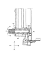
<E−1.ホッパー>
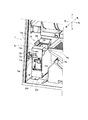
図18は、この遊技機2のホッパー20近傍を拡大して示す部分拡大図である。ホッパー20は、メダル投入口4から投入されたメダルを受け入れる機能、受け入れたメダルを貯留する機能、遊技状況に応じてメダルを計数しつつ払い出す機能を有している。ホッパー20は、キャビネット7内部におけるリール装置9の下方に位置し、底板7j上に載置されている。
<E-1. Hopper>
FIG. 18 is a partially enlarged view showing the vicinity of the hopper 20 of the gaming machine 2 in an enlarged manner. The hopper 20 has a function of receiving medals inserted from the medal insertion slot 4, a function of storing received medals, and a function of paying out medals while counting medals according to the game situation. The hopper 20 is located below the reel device 9 in the cabinet 7 and is placed on the bottom plate 7j.
図19は、ホッパー20を左後方斜め上から見た外観斜視図である。ホッパー20は、貯留タンク20bと払出部20cとを有しており、払出部20cの上方に貯留タンク20bが取り付けられている。
FIG. 19 is an external perspective view of the hopper 20 as viewed obliquely from the upper left rear. The hopper 20 has a storage tank 20b and a payout part 20c, and the storage tank 20b is attached above the payout part 20c.
貯留タンク20bは、メダルを貯留する機能を発揮する。貯留タンク20bの中空内部には、遊技者が投入したメダルが貯留される。貯留タンク20bの周壁の一部には、メダル導入部20dが形成されている。メダル導入部20dは、メダル投入口4から投入されたメダルを受け入れる機能を発揮する部分であって、周囲の上縁よりも一段低く形成されている。メダル投入口4から遊技者によって投入されたメダルは、このメダル導入部20dを介して貯留タンク20b内に貯留される。
The storage tank 20b exhibits a function of storing medals. In the hollow interior of the storage tank 20b, medals thrown by the player are stored. A medal introducing portion 20d is formed on a part of the peripheral wall of the storage tank 20b. The medal introduction part 20d is a part that functions to receive a medal inserted from the medal insertion slot 4, and is formed one step lower than the upper edge of the periphery. The medals inserted by the player from the medal insertion slot 4 are stored in the storage tank 20b through the medal introduction part 20d.
貯留タンク20bの周壁の一部には、漏出口20aも開口形成されている。この漏出口20aは、貯留タンク20bから溢れたメダルを補助金庫58へと導くための開口である。貯留タンク20b内には、タンク内のメダルを漏出口20aへとスムーズに導くための漏出経路20fも配置されている。
A leak outlet 20a is also formed in an opening in a part of the peripheral wall of the storage tank 20b. The leak outlet 20 a is an opening for guiding medals overflowing from the storage tank 20 b to the auxiliary safe 58. A leakage path 20f for smoothly guiding medals in the tank to the leakage outlet 20a is also arranged in the storage tank 20b.
図20は、ホッパー20の払出部20cを右前方斜め上から見た外観斜視図であって、一部を分解して示した図である。払出部20cは、メダルを計数しつつ払い出す機能を発揮する。払出部20cは、払出しモータ72(図21参照)や計数センサ68等の機構部品を収容する収容体20hと払出しモータ72により回転駆動される回転板20jとを有している。
FIG. 20 is an external perspective view of the payout portion 20c of the hopper 20 as viewed obliquely from the upper right front side, and is a view partially exploded. The payout unit 20c exhibits a function of paying out while counting medals. The payout unit 20 c includes a container 20 h that houses mechanical components such as a payout motor 72 (see FIG. 21) and a counting sensor 68, and a rotating plate 20 j that is rotationally driven by the payout motor 72.
収容体20hには、コネクタ63が配置されている(図19)。払出しモータ72や計数センサ68等の電気部品は、コネクタ63及び配線47aによってリール制御基板39のコネクタ47bを中継し、最終的にメイン基板45へと接続されている。配線47aは、コネクタ63によって着脱可能にホッパー20の収容体20hに接続される。したがって、ホッパー20のメンテナンス時等に、容易にホッパー20から配線47aを取り外すことができる。
A connector 63 is disposed in the container 20h (FIG. 19). Electrical components such as the payout motor 72 and the counting sensor 68 are relayed to the connector 47b of the reel control board 39 by the connector 63 and the wiring 47a, and finally connected to the main board 45. The wiring 47a is detachably connected to the container 20h of the hopper 20 by the connector 63. Therefore, the wiring 47a can be easily detached from the hopper 20 during maintenance of the hopper 20 or the like.
回転板20jは、収容体20hの傾斜上面20kに沿って配置され、貯留タンク20bの下方に位置している。回転板20jには、周上に複数の保持穴20mが形成されており、この保持穴20m内にメダルが1枚ずつ保持されるようになっている。
The rotating plate 20j is disposed along the inclined upper surface 20k of the container 20h, and is positioned below the storage tank 20b. A plurality of holding holes 20m are formed on the circumference of the rotating plate 20j, and medals are held one by one in the holding holes 20m.
所定の遊技状況に基づきメダルの払出しを行う場合には、払出しモータ72の駆動により回転板20jが回転する。そうすると貯留タンク20bに貯留されたメダルが、1枚ずつ保持穴20m内に保持される。保持穴20mに保持されたメダルは、放出口20nにおいて外側に押し出される。
When a medal is paid out based on a predetermined game situation, the rotary plate 20j is rotated by driving the payout motor 72. Then, the medals stored in the storage tank 20b are held one by one in the holding hole 20m. The medal held in the holding hole 20m is pushed outward at the discharge port 20n.
放出口20nには、メダルの厚み方向への不用意な移動を規制して、メダルを前方へと円滑に排出させるための押え板64と、放出口20nにおけるメダル受け面20rと押え板64とのメダル厚み方向における間隙を所定間隙に保持するためのスペーサ65とが配置されている。更に、放出口20nにおいては、固定片20pと移動片20qとがメダルの直径より狭い間隔で配置され、移動片20qが固定片20pとの間隔を広げる方向に移動可能とされている。放出口20nにおいて外側に押し出されたメダルは、固定片20pと移動片20qとの隙間に押し入り、固定片20pと移動片20qとの間隔を押し広げながら移動片20qを移動させる。
The discharge port 20n includes a press plate 64 for restricting inadvertent movement of the medal in the thickness direction and smoothly discharging the medal forward, and a medal receiving surface 20r and a press plate 64 at the discharge port 20n. A spacer 65 for holding the gap in the medal thickness direction in a predetermined gap is disposed. Furthermore, in the discharge port 20n, the fixed piece 20p and the moving piece 20q are arranged at a distance narrower than the diameter of the medal, and the moving piece 20q is movable in a direction to increase the distance from the fixed piece 20p. The medal pushed outward at the discharge port 20n enters the gap between the fixed piece 20p and the moving piece 20q, and moves the moving piece 20q while increasing the interval between the fixed piece 20p and the moving piece 20q.
移動片20qは、バネ等の付勢部材により固定片20pとの間隔を狭める方向に付勢されている。その付勢力によってメダルは放出口20nからホッパー20外部へと放出され、遊技機2の受皿17へと排出される。この移動片20qの移動動作が計数センサ68によって検出され、払出枚数が計数されるようになっている。
The moving piece 20q is urged in a direction of narrowing the distance from the fixed piece 20p by an urging member such as a spring. Due to the urging force, the medal is discharged from the discharge port 20 n to the outside of the hopper 20 and discharged to the tray 17 of the gaming machine 2. The movement operation of the moving piece 20q is detected by the counting sensor 68, and the number of payouts is counted.
図21は、ホッパー20の底面図である。収容体20hの底面側に、2つの計数センサ68(68a,68b)及び検出片67が配置されている。計数センサ68は、例えば遮光センサである。検出片67は、中心軸66を中心に揺動可能となっており、中心軸66からずれた位置69に移動片20qが取り付けられている。
FIG. 21 is a bottom view of the hopper 20. Two counting sensors 68 (68a, 68b) and a detection piece 67 are arranged on the bottom surface side of the container 20h. The counting sensor 68 is, for example, a light shielding sensor. The detection piece 67 can swing around the central axis 66, and the moving piece 20 q is attached to a position 69 that is offset from the central axis 66.
メダルの払出しが無い場合(すなわち、初期状態)、検出片67は、2つの計数センサ68のうち一方(例えば、計数センサ68a)のみを遮光し、他方(例えば、計数センサ68b)は透光状態となる。メダルの払出しに伴い移動片20qが移動すると、検出片67が2つの計数センサ68のうち他方(例えば、計数センサ68b)のみを遮光し、一方(例えば、計数センサ68a)は透光状態となる。
When no medal is paid out (that is, in an initial state), the detection piece 67 shields only one of the two counting sensors 68 (for example, the counting sensor 68a) and the other (for example, the counting sensor 68b) is in a light-transmitting state. It becomes. When the moving piece 20q moves as the medal is paid out, the detection piece 67 shields only the other of the two counting sensors 68 (for example, the counting sensor 68b), and the other (for example, the counting sensor 68a) is in a light-transmitting state. .
初期状態において、2つの計数センサ68a,68bのうち一方が遮光状態で、他方が透光状態となる。また、払出しに際して移動片20qが移動した状態においても、2つの計数センサ68a,68bのうち他方のみが遮光状態で、一方が透光状態となる。いずれの場合においても、2つの計数センサ68a,68bの出力信号は、一方(又は他方)がLowとなり、他方(又は一方)がHighとなる。
In the initial state, one of the two counting sensors 68a and 68b is in a light shielding state and the other is in a light transmitting state. Even in the state where the moving piece 20q is moved at the time of payout, only the other of the two counting sensors 68a and 68b is in a light-shielding state and one is in a light-transmitting state. In any case, one (or the other) of the output signals of the two counting sensors 68a and 68b is Low and the other (or one) is High.
例えば、不正な電波を用いてセンサの誤検出を誘発する不正行為が行われると、1つの計数センサ68a,68bの出力信号は、両者ともHigh(又は両者ともLow)となる。したがって、このホッパー20では、電波による不正行為を迅速かつ確実に検知することができる。
For example, when an illegal act that induces erroneous detection of a sensor using an illegal radio wave is performed, the output signals of one counting sensor 68a, 68b are both High (or both are Low). Therefore, the hopper 20 can quickly and reliably detect fraudulent acts caused by radio waves.
図22は、このホッパー20における放出口20n近傍のメダル厚み方向における断面図である。回転板20j側から送り出されたメダルMは、固定片20p及び移動片20qによって弾き出されて受皿17側へと払い出される。
FIG. 22 is a cross-sectional view in the medal thickness direction in the vicinity of the discharge port 20 n of the hopper 20. The medal M sent out from the rotating plate 20j side is flipped out by the fixed piece 20p and the moving piece 20q and paid out to the tray 17 side.
放出口20nにおけるメダル受け面20rは、支持面70と傾斜面71とを有して構成されている。傾斜面71は、金属等の導電性材料で構成されて接地されており、メダルMが接触することによりメダルMの帯電除去が可能となっている。傾斜面71は、根元部71aで支持面70よりも低くなり、先端部71bが根元部71aよりも高くなるように傾斜している。
The medal receiving surface 20r in the discharge port 20n has a support surface 70 and an inclined surface 71. The inclined surface 71 is made of a conductive material such as metal and is grounded, and the medal M can be removed by charging when the medal M comes into contact therewith. The inclined surface 71 is inclined so that the root portion 71a is lower than the support surface 70 and the tip portion 71b is higher than the root portion 71a.
押え板64は少なくともメダル厚み以上の間隙をあけてメダル受け面20rの上方に配置されており、その間隙にメダルMの通過を許容している。押え板64も金属等の導電性材料で構成されて接地されており、メダルMの接触によりメダルMの帯電除去が可能となっている。
The presser plate 64 is disposed above the medal receiving surface 20r with a gap of at least the medal thickness, and allows the medal M to pass through the gap. The presser plate 64 is also made of a conductive material such as a metal and is grounded, and the medal M can be charged and removed by the contact of the medal M.
固定片20p及び移動片20qによって弾き出されたメダルMは、支持面70から傾斜面71へと送り出される。このとき、根元部71aが支持面70よりも低くなっているので、メダルMは、引っかかることなく傾斜面71へと移動する。傾斜面71は、根元部71aから先端部71bに向けて上がり方向に傾斜しているので、傾斜面71へと至ったメダルMは、傾斜面71から押え板64方向への外力を受ける。その結果、メダルMは、その排出速度によっては押え板64に接触する。
The medal M ejected by the fixed piece 20p and the moving piece 20q is sent out from the support surface 70 to the inclined surface 71. At this time, since the root portion 71a is lower than the support surface 70, the medal M moves to the inclined surface 71 without being caught. Since the inclined surface 71 is inclined in the upward direction from the root portion 71a toward the distal end portion 71b, the medal M reaching the inclined surface 71 receives an external force in the direction of the presser plate 64 from the inclined surface 71. As a result, the medal M contacts the presser plate 64 depending on the discharging speed.
メダルMの払出しの際、メダルMは少なくとも傾斜面71に接触することによって帯電除去される。そして、傾斜面71から受ける外力によって、更に押え板64にも接触して帯電除去されることがある。また、メダルMは、押え板64のみに接触して帯電除去されることもある。放出口20nに傾斜面71を配置することにより、スムーズな払出しと確実な帯電除去を実現することができる。
When the medal M is paid out, the medal M is at least removed by being brought into contact with the inclined surface 71. Then, due to the external force received from the inclined surface 71, the presser plate 64 may be further brought into contact with and removed from the charge. Further, the medal M may be removed by electrification by contacting only the presser plate 64. By disposing the inclined surface 71 at the discharge port 20n, smooth discharge and reliable charge removal can be realized.
<F−1.電源ユニット>
図23は、この遊技機2の電源ユニット24近傍を拡大して示す部分拡大図である。電源ユニット24は、この遊技機2の各部に直流電源を供給するためのユニットである、電源ユニット24は、遊技機2のキャビネット7内部における左下方近傍であって、ホッパー20の左方側に配置され、キャビネット7の底板7j上に載置されている。
<F-1. Power supply unit>
FIG. 23 is a partially enlarged view showing the vicinity of the power supply unit 24 of the gaming machine 2 in an enlarged manner. The power supply unit 24 is a unit for supplying DC power to each part of the gaming machine 2. The power supply unit 24 is near the lower left in the cabinet 7 of the gaming machine 2 and on the left side of the hopper 20. It is placed and placed on the bottom plate 7j of the cabinet 7.
この電源ユニット24の前面には、開閉可能な前面扉24aが設けられ、その扉内にオンオフスイッチ(不図示)が配置されている。電源ユニット24は、電源のオンオフ機能を有しているが、リセットスイッチ、打止め有無スイッチ、設定値変更キー等の調整機能を有していない。したがって、この電源ユニット24は汎用性が高く、他の様々な機種にも共通使用することができる。
A front door 24a that can be opened and closed is provided on the front surface of the power supply unit 24, and an on / off switch (not shown) is disposed in the door. The power supply unit 24 has a power on / off function, but does not have adjustment functions such as a reset switch, a stop / presence switch, and a set value change key. Therefore, the power supply unit 24 is highly versatile and can be used in common with other various models.
電源ユニット24の前面には、入力エラー表示LED73a、24V表示LED73b、12V表示LED73c、12V−S表示LED73dが配置されている。これらの表示LED73a〜73dは、遊技機2の各部への正常な電源供給の有無を表示するLEDである。正常に電源供給されている場合には、入力エラー表示LED73aのみが消灯し、その他のLED73b〜73dは点灯する。
On the front surface of the power supply unit 24, an input error display LED 73a, a 24V display LED 73b, a 12V display LED 73c, and a 12V-S display LED 73d are arranged. These display LEDs 73a to 73d are LEDs that display the presence or absence of normal power supply to each part of the gaming machine 2. When the power is normally supplied, only the input error display LED 73a is turned off, and the other LEDs 73b to 73d are turned on.
入力エラー表示LED73aは、電源ユニット24に、適切な電源が供給されている場合に消灯し、電源供給に異常がある場合に点灯する。24V表示LED73bは、電源ユニット24で24Vの直流電源が正常に生成されている場合に点灯し、異常がある場合に消灯する。12V表示LED73cは、メイン基板45に12Vの直流電源が正常に供給されている場合に点灯し、異常がある場合に消灯する。12V−S表示LED73dは、サブ基板49に12Vの直流電源が正常に供給されている場合に点灯し、異常がある場合に消灯する。
The input error display LED 73a is turned off when appropriate power is supplied to the power supply unit 24, and is turned on when there is an abnormality in power supply. The 24V display LED 73b is turned on when a 24V DC power supply is normally generated by the power supply unit 24, and turned off when there is an abnormality. The 12V display LED 73c is turned on when 12V DC power is normally supplied to the main board 45, and turned off when there is an abnormality. The 12V-S display LED 73d is turned on when 12V DC power is normally supplied to the sub-board 49, and turned off when there is an abnormality.
電源ユニット24は、底面を除く全体が樹脂の電源ケース74で覆われており、その内部の電源基板76や各種電子部品が保護されている。電源ケース74は透明又は半透明とされており、電源ユニット24に対して改造等の不正行為が行われた場合の早期発見に寄与している。
The power supply unit 24 is entirely covered with a resin power supply case 74 except for the bottom surface, and the power supply board 76 and various electronic components inside thereof are protected. The power supply case 74 is transparent or semi-transparent, and contributes to early detection when an illegal act such as remodeling is performed on the power supply unit 24.
図24は、電源ユニット24の外観斜視図である。図24においては、電源ユニット24を左前方斜め下から見ている。電源ユニット24の底板24cは、金属板で構成されており、この底板24cが電源ユニット24内部の電源基板76のアースに接続されている。底板24cは、電源ケース74よりも前方に突出しており、その突出部分に取付孔24dが形成されている。取付孔24dは、電源ユニット24をキャビネット7の金属フレームにネジ止めするためのネジ孔である。
FIG. 24 is an external perspective view of the power supply unit 24. In FIG. 24, the power supply unit 24 is seen from diagonally below the left front. The bottom plate 24 c of the power supply unit 24 is made of a metal plate, and the bottom plate 24 c is connected to the ground of the power supply board 76 inside the power supply unit 24. The bottom plate 24c protrudes forward from the power supply case 74, and a mounting hole 24d is formed in the protruding portion. The mounting hole 24 d is a screw hole for screwing the power supply unit 24 to the metal frame of the cabinet 7.
取付孔24dが、電源ケース74の外部に露出するように配置されているので、キャビネット7の金属フレームとのアース接続を容易に着脱することができ、メンテナンス性が向上している。また、電源基板76のアースは、比較的大面積の底板24cを介してキャビネット7の金属フレームに接地される。接地の安定性が高く、ノイズ低減に寄与している。
Since the mounting hole 24d is disposed so as to be exposed to the outside of the power supply case 74, the ground connection with the metal frame of the cabinet 7 can be easily attached and detached, and the maintainability is improved. The ground of the power supply board 76 is grounded to the metal frame of the cabinet 7 via the bottom plate 24c having a relatively large area. Grounding stability is high, contributing to noise reduction.
底板24cには、部分的に切り起こされたフィン24eが多数形成されている。このフィン24eにより、電源ケース74内部と外部との空気の流通が可能となり、放熱が容易となる。また、電源ケース74の背面側にも多数の空気孔(不図示)が開口形成されており、電源ケース74内の冷却に寄与している。
A plurality of fins 24e that are partially cut and raised are formed on the bottom plate 24c. The fins 24e allow air to flow between the inside and outside of the power supply case 74, and heat dissipation is facilitated. A large number of air holes (not shown) are also formed on the back side of the power supply case 74, contributing to cooling of the power supply case 74.
図25(a)は、電源ユニット24を右側方から見た側面図であり、(b)はB−B断面図であり、(c)はC−C断面図である。図26は、電源ユニット24を上方から見た平面図である。電源ユニット24は、電源ケース74内部に電源基板76を有しており、電源基板76上に大型コネクタ24bが実装配置されている。この大型コネクタ24bには配線46aが接続され、リール制御基板のコネクタ46bを介してメイン基板45やサブ基板49に電力が供給されている。
25A is a side view of the power supply unit 24 as viewed from the right side, FIG. 25B is a cross-sectional view taken along the line BB, and FIG. 25C is a cross-sectional view taken along the line CC. FIG. 26 is a plan view of the power supply unit 24 as viewed from above. The power supply unit 24 has a power supply board 76 inside the power supply case 74, and the large connector 24 b is mounted on the power supply board 76. Wiring 46a is connected to the large connector 24b, and power is supplied to the main board 45 and the sub board 49 via the connector 46b of the reel control board.
大型コネクタ24bは、平面視略長方形状を呈しており、電源ケース74の上面74aから露出している。電源ケース74は、2つのケース(74L,74R)が電源基板76を内部に収容し、左右から合わさるように締結されて構成されている。電源ケース74の上面74aには、大型コネクタ24bの長方形外周形状に沿うように略長方形状のコネクタ孔74bが開口形成されている。コネクタ孔74bの開口形状と大型コネクタ24bの平面視形状とが略同形状とされており、大型コネクタ24bとコネクタ孔74bとの隙間が非常に狭くなるように構成されている。したがって、この隙間から電源ケース74内への不正アクセスが有効に防止されている。
The large connector 24 b has a substantially rectangular shape in plan view and is exposed from the upper surface 74 a of the power supply case 74. The power supply case 74 is configured such that two cases (74L, 74R) accommodate the power supply board 76 inside and are fastened so as to be combined from the left and right. A substantially rectangular connector hole 74b is formed in the upper surface 74a of the power supply case 74 so as to follow the rectangular outer peripheral shape of the large connector 24b. The opening shape of the connector hole 74b and the planar view shape of the large connector 24b are substantially the same shape, and the gap between the large connector 24b and the connector hole 74b is very narrow. Therefore, unauthorized access from the gap into the power supply case 74 is effectively prevented.
また、コネクタ孔74bの右側における電源ケース74には、凹部74cが形成されている。この凹部74cは、大型コネクタ24bの側面に沿うように配置されており、大型コネクタ24bの右方向への移動を規制しつつ補強している。大型コネクタ24bへ配線46aをコネクタ接続する際に大きな外力が加わっても、大型コネクタ24bの右方向への不用意な移動は殆どない。大型コネクタ24bが右方向から凹部74cによって支持されているので、右方向への不用意な移動に起因する大型コネクタ24b又はその周囲の破損が有効に予防されている。
The power supply case 74 on the right side of the connector hole 74b has a recess 74c. The recess 74c is disposed along the side surface of the large connector 24b and reinforces while restricting movement of the large connector 24b in the right direction. Even when a large external force is applied when connecting the wiring 46a to the large connector 24b, there is almost no inadvertent movement of the large connector 24b in the right direction. Since the large connector 24b is supported by the recess 74c from the right direction, damage to the large connector 24b or its surroundings due to inadvertent movement in the right direction is effectively prevented.
電源ケース74を構成する2つのケース(74L,74R)は、複数箇所(この遊技機2では4箇所)のネジ75で相互に締結されている。そのネジ75は、電源ユニット24の左側から右方向へと両ケース(74L,74R)を締結しており、ネジ頭がケース74L側、すなわち、左側面74d側に位置している。電源ユニット24は、電源ケース74の左側面74dがキャビネット7の左側面7kと近接して配置された状態で、遊技機2内部に取り付けられる。したがって、遊技機2に電源ユニット24を取り付けた状態で、ネジ75のネジ頭にドライバの先端を差し込むことができず、この状態でネジ75の取外しは殆ど不可能とされている。
Two cases (74L, 74R) constituting the power supply case 74 are fastened to each other by screws 75 at a plurality of locations (four locations in the gaming machine 2). The screws 75 fasten both cases (74L, 74R) from the left side to the right side of the power supply unit 24, and the screw heads are located on the case 74L side, that is, on the left side surface 74d side. The power supply unit 24 is attached to the inside of the gaming machine 2 in a state in which the left side surface 74d of the power supply case 74 is disposed close to the left side surface 7k of the cabinet 7. Therefore, with the power supply unit 24 attached to the gaming machine 2, the tip of the driver cannot be inserted into the screw head of the screw 75, and in this state, the screw 75 is almost impossible to remove.
ケース74Lには、ネジ75に対応する位置にそれぞれザグリ部77Lが凹状形成されており、ネジ頭がそのザグリ部77L内に陥入するようになっている。したがって、左側面74dからネジ頭が出っ張ってしまうことのないように構成されている。また、ネジ75に各々対応する位置には、ケース74R側にもザグリ部77Rが凹状形成されている。したがって、ネジ75の先端部が電源ケース74の右側面74eから突出してしまうことのないように構成されている。なお、ケース74Rが樹脂ケースであるので、締結強度確保のためにネジ75とケース74Rとの螺合長はケースが金属の場合に比較して長く(例えば、1cm以上)確保されている。
In the case 74L, a counterbore 77L is formed in a concave shape at a position corresponding to the screw 75, and the screw head is inserted into the counterbore 77L. Therefore, the screw head is configured not to protrude from the left side surface 74d. Further, at the positions corresponding to the screws 75, a counterbore 77R is also formed in a concave shape on the case 74R side. Therefore, the tip of the screw 75 is configured not to protrude from the right side surface 74e of the power supply case 74. Note that since the case 74R is a resin case, the screw 75 and the case 74R are secured to be longer (for example, 1 cm or more) than the case where the case is made of metal in order to secure the fastening strength.
<G−1.フロント枠全体構造>
図27は、この遊技機2のフロント枠8の分解斜視図である。フロント枠8は、フレーム80に対して透明板8a、左右のサイドレンズユニット18、上部レンズユニット19、操作パネルユニット83、中央パネルユニット84、受皿17が前方から取り付けられて大略構成されている。図27では、中央パネルユニット84以外をフレーム80に対して分解して示している。
<G-1. Front frame overall structure>
FIG. 27 is an exploded perspective view of the front frame 8 of the gaming machine 2. The front frame 8 is generally configured by attaching a transparent plate 8a, left and right side lens units 18, an upper lens unit 19, an operation panel unit 83, a central panel unit 84, and a tray 17 to the frame 80 from the front. In FIG. 27, parts other than the central panel unit 84 are shown disassembled with respect to the frame 80.
図28は、フレーム80を斜め前方から見た外観斜視図である。フレーム80は、外形が正面視略長方形状を呈しており、後方側に配置された金属製のフレーム部材(金属フレーム)35とその前方に配置された樹脂製の樹脂フレーム35bとを有している。フレーム80は、最上方に位置する上部レンズユニット取付部80a、その下方に位置する中央パネル取付部80b、その下方に位置する操作パネル取付部80c、最下方に位置する受皿取付部80dを有している。フレーム80における中央パネル取付部80bの上下には、左右に延びてフレーム80を補強する補強梁部81、82が各々配置されている。
FIG. 28 is an external perspective view of the frame 80 as viewed obliquely from the front. The outer shape of the frame 80 is substantially rectangular when viewed from the front, and includes a metal frame member (metal frame) 35 disposed on the rear side and a resin resin frame 35b disposed in front thereof. Yes. The frame 80 includes an upper lens unit mounting portion 80a positioned at the uppermost position, a central panel mounting portion 80b positioned below the upper lens unit mounting portion 80b, an operation panel mounting portion 80c positioned below the upper portion, and a tray mounting portion 80d positioned at the lowermost position. ing. Reinforcing beam portions 81 and 82 that extend left and right to reinforce the frame 80 are arranged above and below the central panel mounting portion 80b in the frame 80, respectively.
透明板8aは、アクリル、ポリカーボネート等の透明樹脂で形成された正面視略長方形状の平板部材であって、リール11〜13を遊技機2外部から視認可能としつつ、遊技機2内部へのアクセスを防止する機能を有する。透明板8aは、中央パネルユニット84の左右両側に2箇所ずつ、合計4箇所に形成された取付フック84aに係止されて取り付けられるようになっている。
The transparent plate 8a is a substantially rectangular flat plate member made of a transparent resin such as acrylic or polycarbonate, and can access the inside of the gaming machine 2 while making the reels 11 to 13 visible from the outside of the gaming machine 2. It has the function to prevent. The transparent plate 8a is secured to and attached to attachment hooks 84a formed at a total of four locations, two on each of the left and right sides of the central panel unit 84.
フレーム80に対する各ユニットの取付手順は、まずフレーム80の中央パネル取付部80bに対し中央パネルユニット84を後方からネジで締結し、その中央パネルユニット84の取付フック84aに透明板8aを前方から係止する。その後、左右のサイドレンズユニット18をフレーム80に対して前方から取り付け、操作パネルユニット83を操作パネル取付部80cに前方から取り付ける。そして、受皿17を受皿取付部80dに前方から取り付け、上部レンズユニット19を上部レンズユニット取付部80aに前方から取り付ける。
The procedure for attaching each unit to the frame 80 is as follows. First, the central panel unit 84 is fastened to the central panel attachment portion 80b of the frame 80 with screws from the rear, and the transparent plate 8a is engaged with the attachment hook 84a of the central panel unit 84 from the front. Stop. Thereafter, the left and right side lens units 18 are attached to the frame 80 from the front, and the operation panel unit 83 is attached to the operation panel attachment portion 80c from the front. And the saucer 17 is attached to the saucer attaching part 80d from the front, and the upper lens unit 19 is attached to the upper lens unit attaching part 80a from the front.
フレーム80の前面側を、透明板8a、上部レンズユニット19、サイドレンズユニット18、操作パネルユニット83、受皿17が覆うように取り付けられており、各部の隙間が狭くなるように構成されている。したがって、遊技者側(前面側)から遊技機2内部へのアクセスは困難とされている。
The front side of the frame 80 is attached so as to cover the transparent plate 8a, the upper lens unit 19, the side lens unit 18, the operation panel unit 83, and the tray 17 so that the gaps between the respective parts are narrowed. Therefore, it is difficult to access the inside of the gaming machine 2 from the player side (front side).
図29は、右側のサイドレンズユニット18を斜め後方から見た外観斜視図である。左側のサイドレンズユニット18については、右側のものと左右対称の構造をしており、取付方法も略同様であるので、説明を省略する。
FIG. 29 is an external perspective view of the right side lens unit 18 as viewed obliquely from the rear. The left side lens unit 18 has a symmetrical structure with that of the right side, and the mounting method is substantially the same, so the description thereof is omitted.
サイドレンズユニット18の側面18a,18bは、後方に向けて延長されており、その結果サイドレンズユニット18の後面側の水平断面は、大略コ字状となっている。サイドレンズユニット18の側面18a,18b及び後面で囲まれたコ字状部分を内面と称することとする。
The side surfaces 18a and 18b of the side lens unit 18 are extended rearward. As a result, the horizontal cross section of the rear surface side of the side lens unit 18 is substantially U-shaped. A U-shaped portion surrounded by the side surfaces 18a and 18b and the rear surface of the side lens unit 18 is referred to as an inner surface.
サイドレンズユニット18の内面における上部近傍には、上面18c側と側面18a側とに各々フック18dが形成されている。そして、サイドレンズユニット18の底面18eには、下方に突出する係止片18fが形成されている。更に、サイドレンズユニット18の後面には、後方に向けて突出する複数のボス18gが配置されている。
Near the upper portion of the inner surface of the side lens unit 18, hooks 18 d are formed on the upper surface 18 c side and the side surface 18 a side, respectively. Then, a locking piece 18f protruding downward is formed on the bottom surface 18e of the side lens unit 18. Furthermore, a plurality of bosses 18g protruding rearward are disposed on the rear surface of the side lens unit 18.
係止片18fをフレーム80における係止孔80eに上方から挿入し、フック18dをフレーム80の上側頂部近傍に配置された2箇所のフック80fに前方から係合させることで、サイドレンズユニット18をフレーム80に対し仮固定することができる。その後、フレーム80の後方から、複数のボス18gに形成されたネジ穴に、フレーム80を介してネジを螺合することにより、フレーム80に対するサイドレンズユニット18の取付けが完了する。
The locking piece 18f is inserted into the locking hole 80e of the frame 80 from above, and the hook 18d is engaged with the two hooks 80f disposed near the top of the frame 80 from the front, whereby the side lens unit 18 is engaged. It can be temporarily fixed to the frame 80. Thereafter, screws are screwed into the screw holes formed in the plurality of bosses 18g from the rear of the frame 80 via the frame 80, whereby the attachment of the side lens unit 18 to the frame 80 is completed.
図30は、操作パネルユニット83を斜め後方から見た外観斜視図である。操作パネルユニット83の左右側面83aには、後方に向けて突出するフック83bが形成されている。また、操作パネルユニット83の後面側には、後方に向けて突出する複数のボス83cが配置されている。
FIG. 30 is an external perspective view of the operation panel unit 83 as viewed obliquely from the rear. On the left and right side surfaces 83a of the operation panel unit 83, hooks 83b projecting rearward are formed. In addition, a plurality of bosses 83 c protruding rearward are disposed on the rear surface side of the operation panel unit 83.
フレーム80の操作パネル取付部80cには、左右2箇所に係合孔80gが形成されている。左右2箇所の係合孔80gに対し、左右2箇所のフック83bを前方から係合させることにより、操作パネルユニット83をフレーム80に対し仮固定することができる。その後、フレーム80の後方から、複数のボス83cに形成されたネジ穴に、フレーム80を介してネジを螺合することにより、フレーム80に対する操作パネルユニット83の取付けが完了する。
The operation panel mounting portion 80c of the frame 80 is formed with engagement holes 80g at two places on the left and right. The operation panel unit 83 can be temporarily fixed to the frame 80 by engaging the left and right hooks 83b from the front with respect to the left and right engagement holes 80g. Thereafter, screws are screwed into the screw holes formed in the plurality of bosses 83c from the rear of the frame 80 via the frame 80, whereby the operation panel unit 83 is attached to the frame 80.
フレーム80の操作パネル取付部80cにおいては、樹脂フレーム35bが、操作パネルユニット83の側面83aとサイドレンズユニット18の側面18bとの隙間部分を遮蔽するように配置されている。したがって、操作パネルユニット83とサイドレンズユニット18との隙間部分から遊技機2内部に異物を挿入しようとしても樹脂フレーム35bによってその異物の挿入が防止されている。
In the operation panel mounting portion 80 c of the frame 80, the resin frame 35 b is disposed so as to shield a gap portion between the side surface 83 a of the operation panel unit 83 and the side surface 18 b of the side lens unit 18. Therefore, even if a foreign object is to be inserted into the gaming machine 2 from the gap between the operation panel unit 83 and the side lens unit 18, the resin frame 35b prevents the foreign object from being inserted.
図31は、受皿17の一部(右側部分)を斜め後方から見た部分斜視図である。受皿17の後面側には側面近傍位置にフック17aが形成されている。図31には一方のフック17aのみが示されているが、左右両側に2箇所のフック17aが後方に突出形成されている。また、受皿17の後面側には、複数のネジ穴17bが形成されている。
FIG. 31 is a partial perspective view of a part (right side part) of the tray 17 as viewed obliquely from the rear. On the rear surface side of the tray 17, a hook 17 a is formed at a position near the side surface. Although only one hook 17a is shown in FIG. 31, two hooks 17a are formed to protrude rearward on the left and right sides. A plurality of screw holes 17 b are formed on the rear surface side of the tray 17.
フレーム80の受皿取付部80dには、左右2箇所にフック80h(図28において、左側のフック80hは図示省略)が形成されている。左右2箇所のフック17aをフック80hに前方から係合することにより、受皿17をフレーム80に対し仮固定することができる。その後、フレーム80の後方から、複数のネジ穴17bに、フレーム80を介してネジを螺合することにより、フレーム80に対する受皿17の取付けが完了する。
On the tray mounting portion 80d of the frame 80, hooks 80h (the left hook 80h is not shown in FIG. 28) are formed at two places on the left and right. The tray 17 can be temporarily fixed to the frame 80 by engaging the left and right hooks 17a with the hook 80h from the front. Thereafter, screws are screwed into the plurality of screw holes 17b through the frame 80 from the rear of the frame 80, whereby the mounting of the tray 17 to the frame 80 is completed.
図32は、上部レンズユニット19を斜め後方から見た外観斜視図である。上部レンズユニット19の左右側面19aには、後方に向けて突出するフック19bが形成されている。また、上部レンズユニット19の後面側には、後方に向けて突出する複数のボス19cが配置されている。
FIG. 32 is an external perspective view of the upper lens unit 19 as viewed obliquely from the rear. On the left and right side surfaces 19 a of the upper lens unit 19, hooks 19 b that protrude rearward are formed. A plurality of bosses 19c projecting rearward are disposed on the rear surface side of the upper lens unit 19.
左右のサイドレンズユニット18には、フレーム80に取り付けた際に中央寄りとなる側面18bにおける上部近傍位置に、各々取付ガイド18hが形成されている。取付ガイド18hは、上下に規制壁18jを有しており、その間隔がフック19bの上下幅寸法よりも若干大きく形成されている。この取付ガイド18hは、サイドレンズユニット18をフレーム80に取り付けた際に、上部レンズユニット取付部80aの近傍に位置し、左右のフック19bに対応する位置に配置されている。
In the left and right side lens units 18, mounting guides 18 h are formed at positions near the upper portion of the side surface 18 b that is closer to the center when mounted on the frame 80. The mounting guide 18h has a restriction wall 18j on the top and bottom, and the interval is formed to be slightly larger than the vertical width dimension of the hook 19b. The mounting guide 18h is located in the vicinity of the upper lens unit mounting portion 80a when the side lens unit 18 is mounted on the frame 80, and is disposed at a position corresponding to the left and right hooks 19b.
サイドレンズユニット18をフレーム80に取り付けた状態で、上部レンズユニット19を前方から上部レンズユニット取付部80aに取り付けると、左右2箇所のフック19bが左右2箇所の取付ガイド18hによって上下位置を規制された状態で係止される。左右2箇所の取付ガイド18hに対し、左右2箇所のフック19bを前方から係止させることにより、上部レンズユニット19をフレーム80に対し仮固定することができる。その後、フレーム80の後方から、複数のボス19cに形成されたネジ穴に、フレーム80を介してネジを螺合することにより、フレーム80に対する上部レンズユニット19の取付けが完了する。
When the upper lens unit 19 is attached to the upper lens unit attachment portion 80a from the front with the side lens unit 18 attached to the frame 80, the vertical positions of the left and right hooks 19b are regulated by the two right and left attachment guides 18h. It is locked in the state. The upper lens unit 19 can be temporarily fixed to the frame 80 by engaging the left and right hooks 19b from the front with respect to the left and right mounting guides 18h. Thereafter, screws are screwed into the screw holes formed in the plurality of bosses 19c from the rear of the frame 80 via the frame 80, whereby the attachment of the upper lens unit 19 to the frame 80 is completed.
なお、この遊技機2は、フレーム80に対して中央パネルユニット84、透明板8a、サイドレンズユニット18、操作パネルユニット83、受皿17、上部レンズユニット19の順で取り付けることにより組み立てられる。特に、先に透明板8aを取り付けてからサイドレンズユニット18を取り付けること、先にサイドレンズユニット18を取り付けてから上部レンズユニット19を取り付けること、が必要であり、この手順に従い組み立てないと遊技機2が完成しない。逆に、取外しの際は、フレーム80から上部レンズユニット19、受皿17、操作パネルユニット83、サイドレンズユニット18、透明板8a、中央パネルユニット84の順で取り外す必要がある。特に、上部レンズユニット19を取り外した後にサイドレンズユニット18を取り外すこと、サイドレンズユニット18を取り外した後に透明板8aを取り外すこと、が必要であり、この手順に従い取外しを行わないと遊技機2を分解することができない。
The gaming machine 2 is assembled by attaching the central panel unit 84, the transparent plate 8a, the side lens unit 18, the operation panel unit 83, the tray 17 and the upper lens unit 19 in this order to the frame 80. In particular, it is necessary to attach the side lens unit 18 after attaching the transparent plate 8a first, and attach the upper lens unit 19 after attaching the side lens unit 18 first. 2 is not completed. On the contrary, when removing, it is necessary to remove the upper lens unit 19, the tray 17, the operation panel unit 83, the side lens unit 18, the transparent plate 8 a, and the central panel unit 84 from the frame 80 in this order. In particular, it is necessary to remove the side lens unit 18 after removing the upper lens unit 19, and to remove the transparent plate 8 a after removing the side lens unit 18. It cannot be disassembled.
<G−2.操作パネルユニット取付構造>
図33は、フロント枠8における操作パネルユニット83近傍を分解して示す分解斜視図である。図33においては、一部の構成部品を省略している。操作パネルユニット83は、操作パネル本体83dに対し、前方から下マスクユニット85が取り付けられて構成されている。フレーム80の受皿取付部80d近傍には、前方から受皿ベースプレート86が取り付けられている。その受皿ベースプレート86のさらに前方に、操作パネルユニット83とその下方に位置する受皿17とが取り付けられている。
<G-2. Operation panel unit mounting structure>
FIG. 33 is an exploded perspective view showing the vicinity of the operation panel unit 83 in the front frame 8 in an exploded manner. In FIG. 33, some components are omitted. The operation panel unit 83 is configured by attaching a lower mask unit 85 from the front to the operation panel main body 83d. A saucer base plate 86 is attached from the front near the saucer mounting portion 80 d of the frame 80. An operation panel unit 83 and a tray 17 positioned below the operation panel unit 83 are attached further forward of the tray base plate 86.
フレーム80の受皿取付部80d近傍には、下部スピーカユニット88用の開口87が2箇所開口形成されており、その2箇所の開口87に各々対応して、後方から下部スピーカユニット88が取り付けられている。下部スピーカユニット88は、網板88a、下部スピーカ88b、後方カバー88cを有しているが、詳細は後述する。
Two openings 87 for the lower speaker unit 88 are formed in the vicinity of the tray mounting portion 80d of the frame 80, and the lower speaker unit 88 is attached from the rear corresponding to each of the two openings 87. Yes. The lower speaker unit 88 includes a net plate 88a, a lower speaker 88b, and a rear cover 88c, details of which will be described later.
図34は、フロント枠8における受皿ベースプレート86近傍を拡大して示す拡大斜視図である。図34においては、下マスクユニット85及び受皿17を省略している。受皿ベースプレート86は、金属で形成された平板状のプレート部材であって、受皿取付部80dにおいてフレーム80の前面側に取り付けられている。
FIG. 34 is an enlarged perspective view showing the vicinity of the tray base plate 86 in the front frame 8 in an enlarged manner. In FIG. 34, the lower mask unit 85 and the tray 17 are omitted. The saucer base plate 86 is a flat plate member made of metal, and is attached to the front side of the frame 80 at the saucer attachment portion 80d.
受皿ベースプレート86には、2箇所の下部スピーカ88bの放音部(コーン紙部分)に対応するように、放音孔86aが多数開口形成されている。放音孔86aは、放音効果を高めつつ、前方からの異物の挿入等の不正アクセスを防止すべく、多数の小径孔の集合体として構成されており、全体として下部スピーカ88bの放音部形状と同様に円形とされている。
A number of sound emitting holes 86a are formed in the tray base plate 86 so as to correspond to the sound emitting portions (cone paper portions) of the two lower speakers 88b. The sound emitting hole 86a is configured as an assembly of a large number of small diameter holes so as to prevent unauthorized access such as insertion of foreign matter from the front while enhancing the sound emitting effect, and as a whole, the sound emitting part of the lower speaker 88b. Like the shape, it is circular.
操作パネル本体83dの底面83eの一部には、放音孔86aに対応して曲面状の凹部83fが形成されている。凹部83fは、図に示すように、放音孔86aの一部を囲むように位置している。底面83eに凹部83fを形成することにより、下部スピーカ88bを大口径のものとしても放音孔86aの一部が塞がれてしまわずに済み、音質向上を図ることができる。しかも、大口径の下部スピーカ88bを採用しつつも操作パネル本体83dの高さ寸法を大きくとることができる。その結果、下マスクユニット85を大面積とすることができ、この部分に表示される意匠デザインや文字等の情報を目立たせることができる。
A curved recess 83f is formed on a part of the bottom surface 83e of the operation panel body 83d so as to correspond to the sound emission hole 86a. As shown in the figure, the concave portion 83f is positioned so as to surround a part of the sound emitting hole 86a. By forming the concave portion 83f on the bottom surface 83e, even if the lower speaker 88b has a large diameter, a part of the sound emitting hole 86a is not blocked and the sound quality can be improved. Moreover, the height dimension of the operation panel body 83d can be increased while employing the large-diameter lower speaker 88b. As a result, the lower mask unit 85 can have a large area, and information such as design designs and characters displayed in this portion can be made conspicuous.
図35は、操作パネルユニット83における下マスクユニット85近傍の分解斜視図である。下マスクユニット85は、内側マスク85a、意匠プレート85b、外側マスク85cを有している。内側マスク85a及び外側マスク85cは、透明又は半透明の樹脂で形成されており、これらによって意匠プレート85bを挟み込んで保持するようになっている。
FIG. 35 is an exploded perspective view of the operation panel unit 83 in the vicinity of the lower mask unit 85. The lower mask unit 85 includes an inner mask 85a, a design plate 85b, and an outer mask 85c. The inner mask 85a and the outer mask 85c are made of a transparent or translucent resin, and the design plate 85b is sandwiched and held therebetween.
意匠プレート85bは、キャラクタ等の意匠デザインや文字等の情報が記載された表示用部材であって、例えば、透明フィルム上に印刷が施されて構成される。2つのマスク85a,85cによって意匠プレート85bを挟持する構成となっているので、意匠プレート85bの交換を容易に行うことができる。内側マスク85aと外側マスク85cとは、曲面形状を呈するように構成されており、その曲面部分に意匠プレート85bを挟持するようになっている。外側マスク85cに形成された凹部85dに内側マスク85aに形成された凸部85eが嵌入することにより両マスクが係合されて一体化する。内側マスク85aに後方突出するように形成された係合フック85fが、操作パネル本体83dに形成された係合凹部(不図示)に係合されることにより、下マスクユニット85が操作パネル本体83dへと取り付けられる。
The design plate 85b is a display member on which design information such as characters and information such as characters are described, and is configured by printing on a transparent film, for example. Since the design plate 85b is sandwiched between the two masks 85a and 85c, the design plate 85b can be easily replaced. The inner mask 85a and the outer mask 85c are configured to have a curved shape, and the design plate 85b is sandwiched between the curved portions. When the convex portion 85e formed on the inner mask 85a is fitted into the concave portion 85d formed on the outer mask 85c, both masks are engaged and integrated. An engagement hook 85f formed so as to protrude rearward from the inner mask 85a is engaged with an engagement recess (not shown) formed in the operation panel body 83d, whereby the lower mask unit 85 is moved to the operation panel body 83d. It is attached to.
操作パネル本体83dには、凹室89が形成されている。凹室89内には、前方に向けて照明光を発光するLED基板90が2つ配置されている。凹室89の前方に下マスクユニット85が取り付けられるようになっており、このLED基板90からの照明光によって下マスクユニット85の意匠プレート85bが後方から照明される。
A concave chamber 89 is formed in the operation panel body 83d. In the concave chamber 89, two LED substrates 90 that emit illumination light toward the front are disposed. A lower mask unit 85 is attached in front of the concave chamber 89, and the design plate 85b of the lower mask unit 85 is illuminated from behind by the illumination light from the LED substrate 90.
LED基板90は、着脱容易な方法で凹室89内に取り付けられている。すなわち、LED基板90には、その左端近傍に位置決めのための位置決め孔90aが開口形成されている。凹室89内には、LED基板90の右端部を保持する側方保持片89a、LED基板90の中央近傍を保持する中央保持片89b、LED基板90の位置決め孔90aに挿入される位置決め突部89cが形成されている。
The LED substrate 90 is mounted in the concave chamber 89 by a method that allows easy attachment / detachment. That is, the LED board 90 is formed with a positioning hole 90a for positioning near the left end. In the concave chamber 89, a side holding piece 89a that holds the right end of the LED substrate 90, a center holding piece 89b that holds the vicinity of the center of the LED substrate 90, and a positioning protrusion that is inserted into the positioning hole 90a of the LED substrate 90. 89c is formed.
LED基板90の右端部を側方保持片89a部分に挿入し、LED基板90の中央近傍を中央保持片89bに保持させ、位置決め突部89cをLED基板90の位置決め孔90aに挿入することにより、凹室89内へLED基板90が取り付けられる。
By inserting the right end of the LED board 90 into the side holding piece 89a, holding the vicinity of the center of the LED board 90 at the center holding piece 89b, and inserting the positioning protrusion 89c into the positioning hole 90a of the LED board 90, The LED substrate 90 is attached into the concave chamber 89.
更に、LED基板90の位置決め孔90a近傍位置において、押さえ部材91によってLED基板90を保持するようになっている。押さえ部材91は、縦長の樹脂部材であって、上下に2つの係止フック91aを有している。凹室89内の対応位置に形成された2つの係止孔89dに係止フック91aを係止することにより、LED基板90が前方に落下することなく保持されるようになっている。
Further, the LED board 90 is held by the pressing member 91 in the vicinity of the positioning hole 90 a of the LED board 90. The pressing member 91 is a vertically long resin member, and has two hooks 91a on the upper and lower sides. The LED board 90 is held without falling forward by locking the locking hook 91a in the two locking holes 89d formed at the corresponding positions in the concave chamber 89.
<G−3.スピーカ構造>
図36は、フロント枠8aにおける下部スピーカユニット88近傍を分解して示す分解斜視図である。図36においては、フロント枠8aを右斜め後方から矢視している。下部スピーカユニット88は、遊技機2における種々の演出音声、通知音声を遊技者に向けて報知するためのものである。
<G-3. Speaker structure>
FIG. 36 is an exploded perspective view showing the vicinity of the lower speaker unit 88 in the front frame 8a in an exploded manner. In FIG. 36, the front frame 8a is viewed from the diagonally right rear. The lower speaker unit 88 is for notifying the player of various effect sounds and notification sounds in the gaming machine 2.
下部スピーカユニット88は、受皿取付部80dの近傍であって、受皿ベースプレート86の裏側に、フレーム80の後方から左右2箇所に取り付けられている。樹脂フレーム35bの後面側にはスピーカ取付枠35cが形成されており、そのスピーカ取付枠35cの内部が前後方向に貫通開口している。その貫通開口部分に受皿ベースプレート86の放音孔86aが位置するように配置されている。
The lower speaker unit 88 is attached in the vicinity of the saucer mounting portion 80 d and on the back side of the saucer base plate 86 at two locations on the left and right sides from the rear of the frame 80. A speaker mounting frame 35c is formed on the rear surface side of the resin frame 35b, and the inside of the speaker mounting frame 35c is opened through in the front-rear direction. It arrange | positions so that the sound emission hole 86a of the saucer baseplate 86 may be located in the penetration opening part.
下部スピーカユニット88は、網板88a、下部スピーカ88b、後方カバー88cを有して大略構成され、後方カバー88cと下部スピーカ88bとが、スピーカ取付枠35cにネジで共締めされている。
The lower speaker unit 88 is roughly configured to include a mesh plate 88a, a lower speaker 88b, and a rear cover 88c, and the rear cover 88c and the lower speaker 88b are fastened together with screws to the speaker mounting frame 35c.
網板88aは、例えば細い金属線をシート状に網目形成した多孔の金属シートである。前方への音声伝達を実現しつつ、前方(遊技者側)からの下部スピーカ88bへの不正アクセスを防止している。網板88aは、スピーカ取付枠35cの貫通開口部分にセットされ、放音孔86aの後方に配置される。そして、網板88aの後方に下部スピーカ88bのコーン紙(不図示)が位置するようになっている。
The net plate 88a is, for example, a porous metal sheet in which fine metal wires are formed in a sheet form. While realizing forward audio transmission, unauthorized access to the lower speaker 88b from the front (player side) is prevented. The mesh plate 88a is set in the through-opening portion of the speaker mounting frame 35c, and is disposed behind the sound emission hole 86a. The cone paper (not shown) of the lower speaker 88b is positioned behind the mesh plate 88a.
下部スピーカ88bは、遊技機2の演出音声、通知音声を報知するための発音素子である。公知のスピーカと同様に、永久磁石、コイル、コーン紙等を有して形成されている。
The lower speaker 88b is a sounding element for informing the effect sound and notification sound of the gaming machine 2. Like a known speaker, it is formed with permanent magnets, coils, cone paper, and the like.
後方カバー88cは、下部スピーカ88bの後方を覆うための樹脂カバーである。後方カバー88cは、この遊技機2で用いられる遊技媒体(メダル等)が下部スピーカ88bの主要部に接触してしまうことにより、ショートやコーン紙損傷等の不具合が発生するのを防止するためのものである。また、下部スピーカ88bに対する外部からの不正アクセスも防止している。後方カバー88cは、透明又は半透明の樹脂で形成され、内部の下部スピーカ88bを外部から視認可能としている。そのため、下部スピーカ88bに対して万一不正行為が行われた場合でも、早期発見を容易としている。
The rear cover 88c is a resin cover for covering the rear of the lower speaker 88b. The rear cover 88c is used to prevent the occurrence of problems such as short-circuiting or corn paper damage when game media (medals etc.) used in the gaming machine 2 come into contact with the main part of the lower speaker 88b. Is. Further, unauthorized access from the outside to the lower speaker 88b is also prevented. The rear cover 88c is formed of a transparent or translucent resin, and the internal lower speaker 88b is visible from the outside. Therefore, even if an illegal act is performed on the lower speaker 88b, early detection is facilitated.
後方カバー88cは、その後面側の中央部分に開口部88dを有している。この開口部88dから下部スピーカ88bの後面88eが突出している。開口部88dと後面88eとの間には遊技媒体が通過できない程度の隙間が形成されている。この隙間は、下部スピーカ88bからの音声を効率的に遊技者に伝達するための空気通路として機能している。遊技媒体は隙間を通過できないので、隙間を介して遊技媒体が後方カバー88c内部へ侵入することは防止されている。
The rear cover 88c has an opening 88d in the central portion on the rear surface side. A rear surface 88e of the lower speaker 88b protrudes from the opening 88d. A gap is formed between the opening 88d and the rear surface 88e so that the game medium cannot pass therethrough. This gap functions as an air passage for efficiently transmitting the sound from the lower speaker 88b to the player. Since the game medium cannot pass through the gap, the game medium is prevented from entering the rear cover 88c through the gap.
図37は、上部スピーカユニット93を分解して示す分解斜視図である。図37においては、上部レンズユニット19における透明板92a近傍のみを右斜め後方から矢視して図示し、その他の構成部品の図示を省略している。上部レンズユニット19の後方には、上部スピーカユニット93が左右2箇所に取り付けられている。この上部スピーカユニット93も、下部スピーカユニット88と同様に、遊技機2における種々の演出音声、通知音声を遊技者に向けて報知するためのものである。
FIG. 37 is an exploded perspective view showing the upper speaker unit 93 in an exploded manner. In FIG. 37, only the vicinity of the transparent plate 92a in the upper lens unit 19 is shown as viewed from the right oblique rear side, and other components are not shown. On the rear side of the upper lens unit 19, upper speaker units 93 are attached at two places on the left and right. Similar to the lower speaker unit 88, the upper speaker unit 93 is also for notifying the player of various effect sounds and notification sounds in the gaming machine 2.
上部スピーカユニット93は、上部レンズユニット19の後面側の左右2箇所に配置された取付台座19dにネジ止めされている。上部スピーカユニット93は、網板93a、上部スピーカ93b、後方カバー93cを有して大略構成される。後方カバー93cと上部スピーカ93bとが取付台座19dにネジで共締めされている。
The upper speaker unit 93 is screwed to mounting bases 19d arranged at two positions on the left and right sides on the rear surface side of the upper lens unit 19. The upper speaker unit 93 has a mesh plate 93a, an upper speaker 93b, and a rear cover 93c, and is generally configured. The rear cover 93c and the upper speaker 93b are fastened together with screws on the mounting base 19d.
網板93aは、形状は異なるが、その構成及び機能は網板88aと略同様である。網板93aは取付台座19dで囲まれた開口部分にセットされる。網板93aの前方には、放音孔(不図示)が配置されており、遊技者へ向けての効率的な放音と上部スピーカ93bへの不正アクセス防止を実現している。網板93aの後方に上部スピーカ93bのコーン紙93dが位置するようになっている。
The mesh plate 93a is different in shape, but its configuration and function are substantially the same as those of the mesh plate 88a. The mesh plate 93a is set in an opening portion surrounded by the mounting base 19d. A sound emission hole (not shown) is arranged in front of the net 93a, and realizes efficient sound emission toward the player and prevention of unauthorized access to the upper speaker 93b. The cone paper 93d of the upper speaker 93b is positioned behind the mesh plate 93a.
上部スピーカ93bは、遊技機2の演出音声、通知音声を発音するための発音装置であって、形状は異なるが、下部スピーカ88bと略同様の構成である。
The upper speaker 93b is a sounding device for generating the production sound and notification sound of the gaming machine 2, and has a configuration substantially similar to that of the lower speaker 88b, although the shape is different.
後方カバー93cは、上部スピーカ93bの後方を覆うための樹脂カバーである。図38は、上部スピーカ93bと後方カバー93cとの取付状態を示す図であって、(a)は斜視図、(b)は断面図である。
The rear cover 93c is a resin cover for covering the rear of the upper speaker 93b. FIGS. 38A and 38B are diagrams showing an attachment state of the upper speaker 93b and the rear cover 93c, where FIG. 38A is a perspective view and FIG. 38B is a cross-sectional view.
後方カバー93cは、この遊技機2で用いられる遊技媒体(メダル等)が上部スピーカ93bの主要部に接触してしまうことにより、ショートやコーン紙93d損傷等の不具合が発生するのを防止するためのものである。また、上部スピーカ93bへの外部からの不正アクセスも防止している。後方カバー93cは、透明又は半透明の樹脂で形成され、内部の上部スピーカ93bを外部から視認可能としている。そのため、上部スピーカ93bに対して万一不正行為が行われた場合でも、早期発見を容易としている。
The rear cover 93c prevents a malfunction such as a short circuit or damage to the cone paper 93d due to a game medium (such as a medal) used in the gaming machine 2 coming into contact with a main part of the upper speaker 93b. belongs to. Further, unauthorized access from the outside to the upper speaker 93b is also prevented. The rear cover 93c is formed of a transparent or translucent resin, and the internal upper speaker 93b is visible from the outside. Therefore, even if an illegal act is performed on the upper speaker 93b, early detection is facilitated.
後方カバー93cは、その後面側の中央部分に開口部93eを有している。この開口部93eと上部スピーカ93bの後面93fとの間には、遊技媒体が通過できない程度の隙間94aが形成されている。この隙間94aは、上部スピーカ93bからの音声を効率的に遊技者に伝達するための空気通路として機能している。遊技媒体は隙間94aを通過できないので、隙間94aを介して遊技媒体が後方カバー93cの内部93hへ侵入することは防止されている。
The rear cover 93c has an opening 93e in the central portion on the rear surface side. A gap 94a is formed between the opening 93e and the rear surface 93f of the upper speaker 93b so that the game medium cannot pass therethrough. The gap 94a functions as an air passage for efficiently transmitting the sound from the upper speaker 93b to the player. Since the game medium cannot pass through the gap 94a, the game medium is prevented from entering the inside 93h of the rear cover 93c through the gap 94a.
上部スピーカ93bの前面部分における取付板93gと後方カバー93cにおける前面開口との間にも、隙間94bが形成されている。この隙間94b近傍においては、取付台座19dも一段低く形成されており、後方カバー93c内部93hから隙間94bを介して上部スピーカユニット93外部へと空気経路が形成されている。この隙間94bを介した空気経路によっても、上部スピーカ93bからの音声が効率よく遊技者に伝達できるようになっている。もちろん、この隙間94bを介して遊技媒体が後方カバー93c内部へ侵入することは防止されている。
A gap 94b is also formed between the mounting plate 93g in the front portion of the upper speaker 93b and the front opening in the rear cover 93c. In the vicinity of the gap 94b, the mounting base 19d is also formed one step lower, and an air path is formed from the interior 93h of the rear cover 93c to the outside of the upper speaker unit 93 via the gap 94b. The air from the upper speaker 93b can be efficiently transmitted to the player also by the air path through the gap 94b. Of course, the game medium is prevented from entering the rear cover 93c through the gap 94b.
<G−4.錠前ユニット>
図39は、フロント枠8aにおける鍵穴10近傍を斜視した拡大斜視図である。鍵穴10は、操作パネルユニット83の前面右側で、メダル投入口4の下方位置に配置されている。鍵穴10に枠開閉用の鍵を差し込み、回転させるとキャビネット7とフロント枠8aとの施錠状態が解除され、フロント枠8aが前方開閉可能となる。鍵穴10は、後述するキーシリンダ98aの前面に形成されている。鍵穴10の後方側には、錠前ユニット96が配置されている(図40も参照)。
<G-4. Lock Unit>
FIG. 39 is an enlarged perspective view of the vicinity of the keyhole 10 in the front frame 8a. The keyhole 10 is disposed at a position below the medal slot 4 on the right side of the front surface of the operation panel unit 83. When a frame opening / closing key is inserted into the keyhole 10 and rotated, the locked state of the cabinet 7 and the front frame 8a is released, and the front frame 8a can be opened and closed forward. The key hole 10 is formed on the front surface of a key cylinder 98a described later. A lock unit 96 is disposed on the rear side of the keyhole 10 (see also FIG. 40).
図40は、錠前ユニット96の概略構成を示す分解図である。図40においては、フロント枠8aにおけるフレーム80部分を左斜め後方から矢視している。錠前ユニット96は、リンクユニット97、シリンダユニット98、後方カバー99を有して大略構成されている。
FIG. 40 is an exploded view showing a schematic configuration of the lock unit 96. In FIG. 40, the frame 80 portion of the front frame 8a is viewed from the diagonally left rear. The lock unit 96 has a link unit 97, a cylinder unit 98, and a rear cover 99, and is generally configured.
リンクユニット97は、内部に各種リンク機構、ステー部材等を有しており、その一部がシリンダユニット98の回転カム98cと係合している。鍵の回転によって回転カム98cが回転することにより、リンクユニット97内のステー部材が上下移動し、キャビネット7とフロント枠8aとの施錠状態・解錠状態を実現している。リンクユニット97は、ユニット本体97aに対してキーシリンダ保持ステー97bが略直交方向に取り付けられて構成されている。キーシリンダ保持ステー97bには、挿入孔97cが開口形成されており、挿入孔97cにキーシリンダ98aが挿入されるようになっている。
The link unit 97 has various link mechanisms, stay members, and the like inside, and a part of the link unit 97 is engaged with the rotating cam 98 c of the cylinder unit 98. When the rotary cam 98c is rotated by the rotation of the key, the stay member in the link unit 97 is moved up and down to realize the locked state / unlocked state between the cabinet 7 and the front frame 8a. The link unit 97 is configured by attaching a key cylinder holding stay 97b to the unit main body 97a in a substantially orthogonal direction. An insertion hole 97c is formed in the key cylinder holding stay 97b, and the key cylinder 98a is inserted into the insertion hole 97c.
シリンダユニット98は、キーシリンダ98a、取付板98b、回転カム98cを有して大略構成される。キーシリンダ98aは、前面に鍵穴10が形成され、内部に錠前機構(整合する鍵が挿入された場合に回転を許容し、整合しない鍵が挿入された場合に回転を許容しない機構)を有する円柱状機構部品である。
The cylinder unit 98 has a key cylinder 98a, a mounting plate 98b, and a rotating cam 98c, and is generally configured. The key cylinder 98a has a key hole 10 formed in the front surface, and has a lock mechanism (a mechanism that allows rotation when a matching key is inserted and does not allow rotation when a non-matching key is inserted). It is a columnar mechanism part.
キーシリンダ98aの後方には、取付板98bが配置されている。取付板98bは、キーシリンダ98aを前後に延長する方向で保持し、シリンダユニット98をキーシリンダ保持ステー97bに取り付けるためのものである。
A mounting plate 98b is disposed behind the key cylinder 98a. The mounting plate 98b is for holding the key cylinder 98a in a direction extending in the front-rear direction and for attaching the cylinder unit 98 to the key cylinder holding stay 97b.
取付板98bの更に後方には、回転カム98cが配置されている。回転カム98cは、キーシリンダ98aの内部機構と連動しており、キーシリンダ98aに整合する鍵が挿入された場合に鍵によって回転する。その回転動作がリンクユニット97に伝達され、施錠・解錠動作が可能となっている。取付板98bがキーシリンダ保持ステー97bに取り付けられると、キーシリンダ98aは、挿入孔97cを貫通して、樹脂フレーム35bに形成された円筒カバー35d内に挿入されるようになっている。
A rotating cam 98c is disposed further rearward of the mounting plate 98b. The rotating cam 98c is interlocked with the internal mechanism of the key cylinder 98a, and rotates with the key when a key that matches the key cylinder 98a is inserted. The rotation operation is transmitted to the link unit 97, and locking / unlocking operation is possible. When the attachment plate 98b is attached to the key cylinder holding stay 97b, the key cylinder 98a passes through the insertion hole 97c and is inserted into the cylindrical cover 35d formed in the resin frame 35b.
シリンダユニット98の後方には、後方カバー99が取り付けられる。この後方カバー99は、樹脂で形成されており、上下に2箇所の取付孔(不図示)が形成されている。この取付孔及び取付板98bの取付孔98dを介してキーシリンダ保持ステー97bのネジ穴97dにネジが取り付けられ、後方カバー99と取付板98bは、キーシリンダ保持ステー97bに共締めされている。
A rear cover 99 is attached to the rear of the cylinder unit 98. The rear cover 99 is made of resin, and has two attachment holes (not shown) at the top and bottom. A screw is attached to the screw hole 97d of the key cylinder holding stay 97b via the attachment hole and the attachment hole 98d of the attachment plate 98b, and the rear cover 99 and the attachment plate 98b are fastened to the key cylinder holding stay 97b.
後方カバー99がシリンダユニット98の後方を覆うようにネジで取り付けられているので、不正行為等によってキーシリンダ98aごと交換しようとしても、交換作業を容易に行うことができない。そのため、キーシリンダ98aの交換による不正行為を後方カバー99が有効に防止している。一方、後方カバー99は、ドライバによって簡単に取り外すことができるので、メンテンナンス等においてキーシリンダ98aの交換作業を行う際には、さほど作業が煩雑となることはない。
Since the rear cover 99 is attached with screws so as to cover the rear of the cylinder unit 98, even if it is attempted to replace the key cylinder 98a by an illegal act or the like, the replacement work cannot be easily performed. For this reason, the rear cover 99 effectively prevents an illegal act due to the replacement of the key cylinder 98a. On the other hand, since the rear cover 99 can be easily removed by a driver, the work is not so complicated when the key cylinder 98a is exchanged for maintenance or the like.
キーシリンダ98aの後面側には、鍵変更レバー98eが配置されている。後方カバー99には、鍵変更レバー98eに対応する部分に、比較的小サイズの窓部99aが開口形成されている。この窓部99aが小サイズとされているので、キーシリンダ98aの不正交換を防止しつつも外部からの鍵変更レバー98eの操作を可能としている。
A key change lever 98e is disposed on the rear surface side of the key cylinder 98a. The rear cover 99 is formed with a relatively small window portion 99a at a portion corresponding to the key changing lever 98e. Since the window 99a has a small size, it is possible to operate the key change lever 98e from the outside while preventing unauthorized replacement of the key cylinder 98a.
図41は、フレーム80の右上部近傍を右斜め後方から見た斜視図である。図41においては、フレーム部材35のうちトップフレーム35eを後方に分解して示している。
FIG. 41 is a perspective view of the vicinity of the upper right portion of the frame 80 as viewed from the right rear side. In FIG. 41, the top frame 35e of the frame member 35 is shown exploded rearward.
トップフレーム35eは、フレーム80の上部近傍において左右方向に延設され、フレーム80を補強する金属製のアングル部材である。トップフレーム35eの右端部35fは、部分的に切り欠かれた切欠き部とされており、この切欠き部がリンクユニット97のユニット本体97aにおける上端部97eを避ける形状とされている。そのため、この遊技機2においては、錠前ユニット96を取り付けた後にトップフレーム35eの取付け・取外しが可能となっており、メンテナンス性が向上している。
The top frame 35 e is a metal angle member that extends in the left-right direction in the vicinity of the upper portion of the frame 80 and reinforces the frame 80. The right end portion 35f of the top frame 35e is a cutout portion that is partially cut out, and this cutout portion is shaped to avoid the upper end portion 97e of the unit main body 97a of the link unit 97. For this reason, in this gaming machine 2, the top frame 35e can be attached and detached after the lock unit 96 is attached, and the maintainability is improved.
図42は、シリンダユニット98における断面図である。キーシリンダ98aは、円筒カバー35d内に挿入されているが、円筒カバー35dの内径とキーシリンダ98aの外径とが、近い直径値とされており、両者の隙間100が狭くなっている。そのため、この隙間100を通ってピアノ線等の不正具が遊技者側(前方側)からフレーム裏面側(後方側)へと侵入することは、困難とされている。キーシリンダ98a近傍における不正行為が有効に防止されている。
FIG. 42 is a cross-sectional view of the cylinder unit 98. The key cylinder 98a is inserted into the cylindrical cover 35d, but the inner diameter of the cylindrical cover 35d and the outer diameter of the key cylinder 98a are close to each other, and the gap 100 between them is narrow. For this reason, it is considered difficult for an unauthorized tool such as a piano wire to enter from the player side (front side) to the frame back side (rear side) through the gap 100. Unauthorized acts near the key cylinder 98a are effectively prevented.
<G−5.ベットボタンユニット>
図43は、操作パネルユニット83の分解斜視図である。操作パネルユニット83の膨出部8bの上面には、化粧プレート101を介してベットボタンユニット102が取り付けられている。
<G-5. Bet button unit>
FIG. 43 is an exploded perspective view of the operation panel unit 83. A bed button unit 102 is attached to the upper surface of the bulging portion 8 b of the operation panel unit 83 via a decorative plate 101.
図44は、ベットボタンユニット102の拡大斜視図である。ベットボタンユニット102は、遊技者が、遊技に際して操作するための各種ボタンが配置されたボタンユニットであって、MAXベットボタン5a、最小ベットボタン5b、精算ボタン14を有している。MAXベットボタン5aは、1回の遊技(リールの回転停止遊技)において、最大枚数のメダル(例えば、3枚のメダル)を賭ける場合に遊技者が押すためのボタンである。最小ベットボタン5bは、1回の遊技において、最小枚数のメダル(例えば、1枚のメダル)を賭ける場合に遊技者が押すためのボタンである。精算ボタン14は、遊技の終了時等に遊技者が押すためのボタンであって、この精算ボタン14を押すことにより、遊技機2内にクレジット(保留)されていたクレジット枚数のメダルが受皿17に払い出される。
FIG. 44 is an enlarged perspective view of the bet button unit 102. The bet button unit 102 is a button unit in which various buttons for a player to operate in the game are arranged, and includes a MAX bet button 5a, a minimum bet button 5b, and a checkout button 14. The MAX bet button 5a is a button that the player presses when betting the maximum number of medals (for example, three medals) in one game (reel rotation stop game). The minimum bet button 5b is a button that the player presses when betting the minimum number of medals (for example, one medal) in one game. The settlement button 14 is a button for the player to press at the end of the game or the like. When the settlement button 14 is pressed, the medal of the number of credits credited (held) in the gaming machine 2 is received by the tray 17. To be paid out.
ベットボタンユニット102においては、MAXベットボタン5aのボタン面高さが最も高くされており、最小ベットボタン5bや精算ボタン14のボタン面高さは、MAXベットボタン5aよりも低くされている。したがって、MAXベットボタン5aを押そうとした遊技者が、間違って最小ベットボタン5bや精算ボタン14を押してしまうような操作ミスが防止される。
In the bet button unit 102, the button surface height of the MAX bet button 5a is the highest, and the button surface heights of the minimum bet button 5b and the settlement button 14 are lower than the MAX bet button 5a. Therefore, an operation error that a player who tries to press the MAX bet button 5a erroneously presses the minimum bet button 5b or the settlement button 14 is prevented.
図45は、ベットボタンユニット102の膨出部8bへの取付け状態を示す構造図である。図45においては、操作パネルユニット83を裏面側より前方に、下から覗き込むように矢視している。図46は、ベットボタンユニット102を下面側から見た外観斜視図である。ベットボタンユニット102は、ユニット本体102aの下面側に、押さえ部材102b、スイッチユニット102c、爪部材102dが取り付けられている。図47は、ベットボタンユニット102のユニット本体102aを省略して上方から見た斜視図である。爪部材102dの上面側にはセンサ本体102eがネジで固定されている。
FIG. 45 is a structural diagram showing a state in which the bet button unit 102 is attached to the bulging portion 8b. In FIG. 45, the operation panel unit 83 is viewed in an arrow so as to look forward from the back side and from below. FIG. 46 is an external perspective view of the bet button unit 102 as viewed from the lower surface side. In the bet button unit 102, a pressing member 102b, a switch unit 102c, and a claw member 102d are attached to the lower surface side of the unit main body 102a. FIG. 47 is a perspective view of the bet button unit 102 as seen from above with the unit main body 102a omitted. A sensor body 102e is fixed to the upper surface side of the claw member 102d with a screw.
ユニット本体102aは、このベットボタンユニット102の上面及び外郭を構成する樹脂部材である。ユニット本体102aには、MAXベットボタン5a、最小ベットボタン5b、精算ボタン14が押下可能に取り付けられている。MAXベットボタン5aの下方位置には、センサ本体102eを収納する筒状部102fが形成されている。
The unit main body 102a is a resin member that constitutes the upper surface and outline of the bet button unit 102. A MAX bet button 5a, a minimum bet button 5b, and a settlement button 14 are attached to the unit main body 102a so as to be pressed. A cylindrical portion 102f that houses the sensor main body 102e is formed below the MAX bet button 5a.
押さえ部材102bは、最小ベットボタン5b及び精算ボタン14を付勢するバネを保持するための部材である。その押さえ部材102bの下方には、スイッチユニット102cが配置されている。スイッチユニット102cは、最小ベット用スイッチ102g、精算用スイッチ102hを有しており、各々が最小ベットボタン5bから下方に延設された操作片(不図示)及び精算ボタン14から下方に延設された操作片(不図示)によって押下可能となっている。最小ベットボタン5bが押下されると、最小ベット用スイッチ102gが操作片によって押下され、ボタン押下が検出されるようになっている。また、精算ボタン14が押下されると精算用スイッチ102hが操作片によって押下され、ボタン押下が検出されるようになっている。
The holding member 102b is a member for holding a spring that urges the minimum bet button 5b and the settlement button 14. A switch unit 102c is disposed below the pressing member 102b. The switch unit 102c has a minimum bet switch 102g and a settlement switch 102h, each of which extends downward from the minimum bet button 5b and an operation piece (not shown) extended from the settlement button 14. It can be pressed by an operation piece (not shown). When the minimum bet button 5b is pressed, the minimum bet switch 102g is pressed by the operation piece, and the button press is detected. When the settlement button 14 is depressed, the settlement switch 102h is depressed by the operation piece so that the button depression is detected.
センサ本体102eは、MAXベットボタン5aの押下を検出するためのセンサ102jとLED102kとを有している。センサ102jは投受光センサとされており、MAXベットボタン5aから下方に延設された検出片(不図示)が凹部102mを進退することにより、ボタン押下が検出できるように構成されている。
The sensor main body 102e includes a sensor 102j and an LED 102k for detecting pressing of the MAX bet button 5a. The sensor 102j is a light emitting / receiving sensor, and is configured such that a button press can be detected by a detection piece (not shown) extending downward from the MAX bet button 5a moving forward and backward through the recess 102m.
LED102kは、MAXベットボタン5aを下から照明するための照明光源である。MAXベットボタン5aは、全部又は一部が透明又は半透明とされて、例えば、意匠や文字等が印刷されている。LED102kにより下方から遊技者に向けてMAXベットボタン5aを照明すると、その表面に施された意匠や文字等が浮かび上がるように演出照明される。
The LED 102k is an illumination light source for illuminating the MAX bet button 5a from below. The MAX bet button 5a is entirely or partially transparent or semi-transparent, for example, printed with designs, characters, and the like. When the MAX bet button 5a is illuminated toward the player from the lower side by the LED 102k, effect lighting is performed so that the design, characters, and the like applied to the surface of the button 102a emerge.
センサ本体102eにおいては、センサ102jとLED102kとが、樹脂でモールドされ一体化されている。また、その後面側にコネクタ102nも一体的に樹脂モールドされており、センサ本体102eは、全体として電子基板を有さない基板レス構造とされている。
In the sensor body 102e, the sensor 102j and the LED 102k are molded and integrated with resin. Further, the connector 102n is also integrally resin-molded on the rear surface side, and the sensor body 102e has a board-less structure that does not have an electronic board as a whole.
爪部材102dは、ベットボタンユニット102全体を膨出部8b上面に係合するための部材であって、膨出部8bに係合する爪部102pを有している。一端部近傍において係止孔102qを有してユニット本体102aのフック102rに係止され、他端部近傍において取付孔102sを有してユニット本体102aにネジ止めされるようになっている。つまり、係止孔102qによる係止と、取付孔102sによるネジ止めという、2箇所で2種類の取付態様でユニット本体102aに取り付けられている。
The claw member 102d is a member for engaging the entire bet button unit 102 with the upper surface of the bulging portion 8b, and has a claw portion 102p for engaging with the bulging portion 8b. A locking hole 102q is provided in the vicinity of one end portion and is locked to the hook 102r of the unit main body 102a, and a mounting hole 102s is provided in the vicinity of the other end portion and is screwed to the unit main body 102a. That is, the unit body 102a is attached to the unit main body 102a in two types of attachment modes, namely, the engagement by the engagement hole 102q and the screwing by the attachment hole 102s.
ベットボタンユニット102は、爪部102pによって膨出部8bに係合した上で、2箇所のネジ103a,103bで膨出部8bの裏面側に取り付けられている。ネジ103aは、ユニット本体102aの取付孔102tを膨出部8bに取り付ける。ネジ103bは、爪部材102dの取付孔102uを膨出部8bに取り付ける。
The bet button unit 102 is attached to the back surface side of the bulging portion 8b with two screws 103a and 103b after being engaged with the bulging portion 8b by the claw portion 102p. The screw 103a attaches the attachment hole 102t of the unit main body 102a to the bulging portion 8b. The screw 103b attaches the attachment hole 102u of the claw member 102d to the bulging portion 8b.
2箇所のネジ103a,103bによって、ユニット本体102aと爪部材102dという2種類の部材をネジ止めすることにより、ベットボタンユニット102全体を膨出部8bに固定している。ベットボタンユニット102の膨出部8bからの取外しを複雑化することにより、不正行為(ベットボタンユニット102の不正な取外し行為)を行い難くしている。
The entire bet button unit 102 is fixed to the bulging portion 8b by screwing two types of members, that is, the unit main body 102a and the claw member 102d with two screws 103a and 103b. By complicating the removal of the bet button unit 102 from the bulging portion 8b, an illegal act (an illegal removal action of the bet button unit 102) is made difficult.
<G−6.ストップボタンユニット>
図43に示すように、膨出部8bの前面側には、ストップボタンユニット104が前方から取り付けられている。ストップボタンユニット104は、前面パネル105上に3つのストップボタン21〜23が配置されている。各ストップボタン21〜23は、スタートレバー3の操作によって回転を開始した各リール11〜13の回転を停止させるためのボタンである。
<G-6. Stop button unit>
As shown in FIG. 43, a stop button unit 104 is attached to the front side of the bulging portion 8b from the front. The stop button unit 104 has three stop buttons 21 to 23 arranged on the front panel 105. Each of the stop buttons 21 to 23 is a button for stopping the rotation of each of the reels 11 to 13 that has started rotating by the operation of the start lever 3.
図48は、ストップボタンユニット104を右斜め後方から見た外観斜視図である。ストップボタンユニット104は、前面パネル105の後方にセンサユニット106がネジ107により固定されている。すなわち、ネジ107を取り外すことにより、ストップボタン21〜23が配された前面パネル105の部分とセンサユニット106の部分とに分離することができる。
FIG. 48 is an external perspective view of the stop button unit 104 as viewed from the right rear side. In the stop button unit 104, a sensor unit 106 is fixed to the back of the front panel 105 with screws 107. That is, by removing the screw 107, the front panel 105 portion where the stop buttons 21 to 23 are arranged and the sensor unit 106 portion can be separated.
膨出部8bの前面側に取り付けられるストップボタン21〜23が配された前面パネル105部分がセンサユニット106部分から簡単に分離可能とされているので、遊技者に視認される部分の意匠デザイン等が容易に変更可能となっている。
Since the front panel 105 portion provided with stop buttons 21 to 23 attached to the front side of the bulging portion 8b can be easily separated from the sensor unit 106 portion, the design design of the portion visually recognized by the player, etc. Can be easily changed.
図49は、センサユニット106部分を右斜め前方から見た斜視図である。図49においては、ストップボタンユニット104における前面パネル105及びストップボタン21〜23を省略している。
FIG. 49 is a perspective view of the sensor unit 106 viewed from the right front side. In FIG. 49, the front panel 105 and the stop buttons 21 to 23 in the stop button unit 104 are omitted.
センサユニット106の前面には、ストップボタン21〜23に各々対応する位置に凹室106a〜106cが形成され、その凹室106a〜106c内にそれぞれセンサ本体108が配置されている。このセンサ本体108は、センサ本体102eと略同様の構成とされている。すなわち、センサ(不図示)とLED109とが樹脂でモールドされて一体化され、基板レス構造とされている。センサは例えば投受光センサであり、後述する支持部材111の後方に延設された検出片(不図示)が検出領域を進退することにより、ストップボタン21〜23の押下を検出するようになっている。
On the front surface of the sensor unit 106, recessed chambers 106a to 106c are formed at positions corresponding to the stop buttons 21 to 23, respectively, and sensor bodies 108 are disposed in the recessed chambers 106a to 106c, respectively. The sensor body 108 has a configuration substantially similar to that of the sensor body 102e. That is, the sensor (not shown) and the LED 109 are molded with a resin and integrated to form a substrate-less structure. The sensor is, for example, a light projecting / receiving sensor, and a detection piece (not shown) extending behind a supporting member 111 described later detects the pressing of the stop buttons 21 to 23 by moving forward and backward through the detection area. Yes.
凹室106a〜106c内には、バネ110により前方に向けて付勢された支持部材111が前後移動可能に収納されている。この支持部材111がストップボタン21〜23の後方を前方に付勢しつつ支持し、押下されたストップボタン21〜23の復帰を実現している。そして、ストップボタン21〜23の前後移動と支持部材111の前後移動とが同期している。バネ110や支持部材111等の機構部品もセンサユニット106側に配置されているので、ストップボタンユニット104の意匠変更の際には、最小限の部品(前面パネル105及びストップボタン21〜23)を変更すれば足りる。
In the concave chambers 106a to 106c, a support member 111 biased forward by a spring 110 is accommodated so as to be movable back and forth. The support member 111 supports the back of the stop buttons 21 to 23 while urging the back of the stop buttons 21 to 23 forward, thereby realizing the return of the pressed stop buttons 21 to 23. And the back-and-forth movement of the stop buttons 21 to 23 and the back-and-forth movement of the support member 111 are synchronized. Since mechanical parts such as the spring 110 and the support member 111 are also arranged on the sensor unit 106 side, when changing the design of the stop button unit 104, the minimum parts (front panel 105 and stop buttons 21 to 23) are required. It is enough to change it.
図45にストップボタンユニット104が膨出部8bに取り付けられた状態が示されている。図45では、膨出部8bを後方から見ている。ストップボタンユニット104の後面には、センサ本体108に樹脂モールドされたコネクタ112が配置されている。ストップボタンユニット104は、膨出部8bの前方から取り付けられ、後方から左右2箇所のネジで膨出部8bに固定される。
FIG. 45 shows a state where the stop button unit 104 is attached to the bulging portion 8b. In FIG. 45, the bulging portion 8b is viewed from the rear. A connector 112 resin-molded on the sensor body 108 is disposed on the rear surface of the stop button unit 104. The stop button unit 104 is attached from the front of the bulging portion 8b, and is fixed to the bulging portion 8b with two screws on the left and right from the rear.
図45においては、ストップボタンユニット104を固定する左側のネジ113が示されている。右側のネジは示されていないが、右側のネジを挿入するために膨出部8b後方に突出形成された中空ボス114が示されている。この中空ボス114の後方側には、メダル投入口4から投入されたメダルを受け入れるセレクタユニット(図45においては図示省略)が取り付けられている。したがって、セレクタユニットの取付状態においては、中空ボス114内のネジにアクセスできないようになっている。キャビネット7に対してフロント枠8を開放しただけでは、ストップボタンユニット104の取外しができず、ストップボタンユニット104の取外しによる不正行為が簡単には行えないようになっている。
In FIG. 45, the left screw 113 for fixing the stop button unit 104 is shown. Although the right screw is not shown, a hollow boss 114 is formed that protrudes behind the bulging portion 8b in order to insert the right screw. A selector unit (not shown in FIG. 45) for receiving medals inserted from the medal insertion slot 4 is attached to the rear side of the hollow boss 114. Therefore, the screw in the hollow boss 114 cannot be accessed when the selector unit is attached. The opening of the front frame 8 with respect to the cabinet 7 does not allow the stop button unit 104 to be removed, and unauthorized actions due to the removal of the stop button unit 104 cannot be easily performed.
<G−7.セレクタユニット>
図50は、この遊技機2におけるセレクタユニット115近傍の分解斜視図である。図50においては、フレーム80の右側近傍を左斜め後方から矢視している。セレクタユニット115は、膨出部8bの裏面側付近に取り付けられており、メダル投入口4の下方に位置している。
<G-7. Selector unit>
FIG. 50 is an exploded perspective view of the vicinity of the selector unit 115 in the gaming machine 2. In FIG. 50, the vicinity of the right side of the frame 80 is viewed from the diagonally backward left side. The selector unit 115 is attached in the vicinity of the back surface side of the bulging portion 8 b and is located below the medal slot 4.
メダル投入口4が開口形成された投入口ユニット4pの下方であって、樹脂フレーム35bの裏面側には、セレクタユニット取付ブラケット116が取り付けられている。セレクタユニット取付ブラケット116は、例えば板金で構成されたブラケット部材であって、大略形状が後方に開口するコ字状とされている。
A selector unit mounting bracket 116 is attached to the lower side of the resin frame 35b below the insertion port unit 4p in which the medal insertion port 4 is opened. The selector unit mounting bracket 116 is a bracket member made of, for example, a sheet metal, and has a generally U-shape that opens rearward.
セレクタユニット取付ブラケット116の上部には、2箇所の取付孔116aと位置決め孔116bとが形成されている。投入口ユニット4pの位置決め凸部4bが位置決め孔116bに挿入され、投入口ユニット4pのネジ穴4aに取付孔116aを介してネジが取り付けられることによって投入口ユニット4pがセレクタユニット取付ブラケット116にネジ止めされている。位置決め凸部4b及び位置決め孔116bを用いて取り付けられるので、セレクタユニット取付ブラケット116に対して位置精度よく投入口ユニット4pを取り付けることができる。
In the upper part of the selector unit mounting bracket 116, two mounting holes 116a and a positioning hole 116b are formed. The positioning projection 4b of the insertion port unit 4p is inserted into the positioning hole 116b, and a screw is attached to the screw hole 4a of the insertion port unit 4p via the attachment hole 116a, whereby the insertion port unit 4p is screwed to the selector unit mounting bracket 116. It has been stopped. Since it is attached using the positioning convex portion 4b and the positioning hole 116b, the insertion port unit 4p can be attached to the selector unit mounting bracket 116 with high positional accuracy.
セレクタユニット115は、メダル投入口4から投入されたメダルを受け入れて各種処理を行うユニットである。図51はセレクタユニット115内部のメダル通路115bを示す内部構造図である。図51においては、本体部115fと蓋部115gとを開放した状態を示しているが、通常使用状態においては、両者が閉鎖されることにより、後述する導入口115a、メダル通路115b、導出口115c、排出口115dが構成される。
The selector unit 115 is a unit that receives a medal inserted from the medal slot 4 and performs various processes. FIG. 51 is an internal structure diagram showing the medal passage 115b in the selector unit 115. FIG. FIG. 51 shows a state in which the main body 115f and the lid 115g are opened. However, in a normal use state, both of them are closed, so that an inlet 115a, a medal passage 115b, and a outlet 115c described later are closed. A discharge port 115d is formed.
適正なメダルが導入口115aから導入されると、メダルはメダル通路115bを通って導出口115cからホッパー20へと至るようになっている。また、不正なメダル(例えば、直径の異なるメダル)が導入口115aから導入されると、メダル通路115bの途中で流路が切り替えられて、排出口115dから排出されて受皿17へと至るようになっている。
When an appropriate medal is introduced from the introduction port 115a, the medal passes from the outlet port 115c to the hopper 20 through the medal passage 115b. In addition, when an illegal medal (for example, a medal having a different diameter) is introduced from the introduction port 115a, the flow path is switched in the middle of the medal passage 115b, and is discharged from the discharge port 115d to reach the tray 17. It has become.
その他、セレクタユニット115は、複数のメダル通過センサからの出力信号に基づいて、メダルの通過方向を特定する処理も行う。これらの処理を実行するために、セレクタユニット115は、駆動源(ソレノイド等)、センサ、各種可動片等を有している。
In addition, the selector unit 115 also performs a process of specifying the passing direction of medals based on output signals from a plurality of medal passing sensors. In order to execute these processes, the selector unit 115 includes a drive source (solenoid or the like), a sensor, various movable pieces, and the like.
セレクタユニット115は、左右側面に各々2個ずつの位置決め突起115eを有している。セレクタユニット取付ブラケット116には、位置決め突起115eに対応する位置に、位置決め突起115eが挿入されるセレクタ位置決め孔(不図示)が形成されている。位置決め突起115eをセレクタ位置決め孔に挿入することで、セレクタユニット取付ブラケット116に対してセレクタユニット115を位置精度よく取り付けることができるようになっている。その結果、セレクタユニット取付ブラケット116を介して、投入口ユニット4pとセレクタユニット115との相対位置関係が高精度となる。
The selector unit 115 has two positioning projections 115e on each of the left and right side surfaces. The selector unit mounting bracket 116 is formed with a selector positioning hole (not shown) into which the positioning protrusion 115e is inserted at a position corresponding to the positioning protrusion 115e. By inserting the positioning projection 115e into the selector positioning hole, the selector unit 115 can be attached to the selector unit mounting bracket 116 with high positional accuracy. As a result, the relative positional relationship between the insertion port unit 4p and the selector unit 115 becomes high accuracy via the selector unit mounting bracket 116.
なお、セレクタユニット取付ブラケット116に対してセレクタユニット115を取り付ける際は、セレクタユニット取付ブラケット116のコ字状開口部分に、後方からセレクタユニット115を挿入するだけで取り付けが完了するようになっている。その際、セレクタユニット取付ブラケット116の左側面に固定された樹脂製の取付ガイド116cが、その弾性に基づいて開口幅を広げるように撓み、セレクタユニット115の受け入れを容易にしている。
When the selector unit 115 is attached to the selector unit attachment bracket 116, the attachment is completed simply by inserting the selector unit 115 from the rear into the U-shaped opening of the selector unit attachment bracket 116. . At that time, the resin mounting guide 116c fixed to the left side surface of the selector unit mounting bracket 116 is bent so as to widen the opening width based on its elasticity, thereby facilitating the reception of the selector unit 115.
図52は、セレクタユニット取付ブラケット116を後方から見た後面図である。図52は、セレクタユニット115を取り外した状態であり、その図示を省略している。セレクタユニット取付ブラケット116の支持面116dには、略長方形状の開口部116eが開口形成されている。開口部116eは、ストップボタンユニット104の中空ボス114の後方正面に位置している。
FIG. 52 is a rear view of the selector unit mounting bracket 116 as seen from the rear. FIG. 52 shows a state in which the selector unit 115 is removed, and illustration thereof is omitted. A substantially rectangular opening 116 e is formed in the support surface 116 d of the selector unit mounting bracket 116. The opening 116 e is located on the rear front side of the hollow boss 114 of the stop button unit 104.
セレクタユニット115を取り外さないと、中空ボス114内のネジ114aにアクセスできないが、セレクタユニット取付ブラケット116を取り外さなくても開口部116eを介してネジ114aをドライバで取り外すことができるようになっている。セレクタユニット取付ブラケット116を樹脂フレーム35bに装着したままでストップボタンユニット104を操作パネルユニット83の前方から取り外すことができるので、メンテナンス性の向上に寄与している。
If the selector unit 115 is not removed, the screw 114a in the hollow boss 114 cannot be accessed, but the screw 114a can be removed with a screwdriver through the opening 116e without removing the selector unit mounting bracket 116. . Since the stop button unit 104 can be removed from the front of the operation panel unit 83 while the selector unit mounting bracket 116 is mounted on the resin frame 35b, it contributes to improvement in maintenance.
<G−8.中央表示基板>
図53は、中央表示基板117近傍の分解斜視図である。中央表示基板117は、フレーム80の上下方向における中央やや下方の左側面近傍に位置し、膨出部8bの裏面側に配置されている。中央表示基板117は、複数のコネクタを有してスタートレバー3、ベットボタンユニット102、ストップボタンユニット104等と接続された中継基板であって、メイン基板45へと配線接続されている。中央表示基板117は、後述するようにセレクタユニット115にも接続されている。
<G-8. Central display board>
FIG. 53 is an exploded perspective view in the vicinity of the central display substrate 117. The central display board 117 is located in the vicinity of the left side surface slightly below the center in the vertical direction of the frame 80, and is disposed on the back side of the bulging portion 8b. The central display board 117 is a relay board having a plurality of connectors and connected to the start lever 3, the bet button unit 102, the stop button unit 104, and the like, and is connected to the main board 45 by wiring. The central display board 117 is also connected to the selector unit 115 as will be described later.
中央表示基板117は、基板ケース118で覆われている。基板ケース118は、ベースカバー118a、蓋カバー118b、開閉カバー118c、レバー後部カバー118dを有して構成されている。ベースカバー118aと蓋カバー118bとが、中央表示基板117の前後を覆うように構成されている。図53においては、基板ケース118の一部を分解して示している。
The central display substrate 117 is covered with a substrate case 118. The substrate case 118 includes a base cover 118a, a lid cover 118b, an opening / closing cover 118c, and a lever rear cover 118d. The base cover 118a and the lid cover 118b are configured to cover the front and rear of the central display substrate 117. In FIG. 53, a part of the substrate case 118 is disassembled.
図54は、基板ケース118の右後方を斜め下方から斜視した斜視図である。基板ケース118は、透明又は半透明の樹脂で形成されている。したがって、基板ケース118の外部から中央表示基板117が視認可能となっている。したがって、中央表示基板117に対し、改造等の不正行為が行われた場合でも迅速な発見が可能となっている。ベースカバー118aは、中央表示基板117の主として前方を覆うカバーであって、樹脂フレーム35bにネジ止めされている。そして、ベースカバー118aに対して中央表示基板117がネジ止めされて固定されている。
FIG. 54 is a perspective view of the right rear of the substrate case 118 as seen obliquely from below. The substrate case 118 is made of a transparent or translucent resin. Therefore, the central display substrate 117 is visible from the outside of the substrate case 118. Therefore, even when an illegal act such as remodeling is performed on the central display board 117, a quick discovery is possible. The base cover 118a is a cover that mainly covers the front of the central display board 117, and is screwed to the resin frame 35b. The central display board 117 is fixed with screws to the base cover 118a.
蓋カバー118bは、中央表示基板117の主として後方を覆うカバーであって、ベースカバー118aに対してネジ止め固定されるようになっている。ベースカバー118aの上面には、左右2箇所の係止突起119が突出形成されており、蓋カバー118bの上面には、係止突起119に対応する位置に係止孔120が開口形成されている。蓋カバー118bの取付け前に、両者の上面において係止突起119に係止孔120を係止させることにより、ベースカバー118aに対し蓋カバー118bの仮止めが可能となっている。ベースカバー118aの上に蓋カバー118bを置くだけで係止突起119が係止孔120に係止されて蓋カバー118bが落下しない。したがって、蓋カバー118bの取付け工程が簡便となる。
The lid cover 118b is a cover that mainly covers the rear of the central display board 117, and is fixed to the base cover 118a with screws. The upper surface of the base cover 118a is formed with two protruding projections 119 on the left and right, and the upper surface of the lid cover 118b is formed with an engagement hole 120 at a position corresponding to the locking projection 119. . Before the cover cover 118b is attached, the cover cover 118b can be temporarily fixed to the base cover 118a by locking the lock holes 120 to the lock protrusions 119 on the upper surfaces of both. By simply placing the lid cover 118b on the base cover 118a, the locking projection 119 is locked in the locking hole 120, and the lid cover 118b does not fall. Therefore, the process of attaching the lid cover 118b is simplified.
ベースカバー118aに対し、蓋カバー118bをネジ止めした後に、そのネジ止め部分に封止部材126が取り付けられるようになっている。封止部材126は、表面に半透明の薄膜フィルムが形成された部材であって、蓋カバー118bのネジ止め部分に取外し困難に取り付けられる。蓋カバー118bを取り外そうとすると、薄膜フィルムを突き破ってドライバーでネジを外す必要があり、その取外し行為の痕跡が残存するようになっている。したがって、蓋カバー118bの不正な取外し、すなわち中央表示基板117への不正アクセスを有効に防止している。
After the lid cover 118b is screwed to the base cover 118a, the sealing member 126 is attached to the screwed portion. The sealing member 126 is a member having a translucent thin film formed on the surface, and is attached to the screwed portion of the lid cover 118b with difficulty in removal. In order to remove the lid cover 118b, it is necessary to break through the thin film and remove the screw with a screwdriver, and the trace of the removal action remains. Therefore, unauthorized removal of the lid cover 118b, that is, unauthorized access to the central display board 117 is effectively prevented.
蓋カバー118bの上面には、大開口121と小開口122も形成されている。ベットボタンユニット102、ストップボタンユニット104、演出ボタンユニット14a等からのハーネスは、大開口121を通って中央表示基板117上の各種コネクタに接続されている。スタートレバー3からのハーネスは、レバー後部カバー118dによって覆われて小開口122を通って中央表示基板117上のコネクタに接続されている。レバー後部カバー118dは、スタートレバー3の後部から小開口122までを覆って小開口122内に侵入している。スタートレバー3からのハーネスは、外部からのアクセスが一段と困難とされている。
A large opening 121 and a small opening 122 are also formed on the upper surface of the lid cover 118b. Harnesses from the bet button unit 102, the stop button unit 104, the effect button unit 14a, and the like are connected to various connectors on the central display board 117 through the large opening 121. The harness from the start lever 3 is covered by the lever rear cover 118d and is connected to the connector on the central display board 117 through the small opening 122. The lever rear cover 118d covers the portion from the rear portion of the start lever 3 to the small opening 122 and enters the small opening 122. The harness from the start lever 3 is more difficult to access from the outside.
セレクタユニット115は、中央表示基板117の右方に配置されており、セレクタユニット115からのハーネスは中央表示基板117のコネクタ123に接続されている。コネクタ123は、開閉カバー118cの前方に位置し、開閉カバー118cを開放することにより、外部に露出し、コネクタ123の挿脱が容易となっている。
The selector unit 115 is disposed on the right side of the central display board 117, and the harness from the selector unit 115 is connected to the connector 123 of the central display board 117. The connector 123 is located in front of the opening / closing cover 118c, and is opened to the outside by opening the opening / closing cover 118c, so that the connector 123 can be easily inserted and removed.
開閉カバー118cは、ベースカバー118aに対し、上下に回動可能とされたカバーであり、上方回動状態でコネクタ123を閉鎖し、下方回動状態でコネクタ123を開放する。開閉カバー118cは、通常使用状態においては蓋カバー118bに後方突出形成された係止フック124に係止されて閉鎖状態を実現し、セレクタユニット115からのハーネスやコネクタ123への不正アクセスを防止している。
The open / close cover 118c is a cover that can be turned up and down with respect to the base cover 118a. The open / close cover 118c closes the connector 123 in the upward rotation state and opens the connector 123 in the downward rotation state. In the normal use state, the opening / closing cover 118c is locked by a locking hook 124 formed to protrude rearward from the lid cover 118b to realize a closed state, thereby preventing unauthorized access to the harness and the connector 123 from the selector unit 115. ing.
一方、セレクタユニット115の清掃時等のメンテナンスにおいては、コネクタ123を取り外す必要がある。係止フック124を解除して開閉カバー118cを開放状態とすると、外部から容易にコネクタ123へとアクセスができ、コネクタ123の挿脱が容易となる。したがって、開閉カバー118cは、通常時の不正防止とメンテナンス時のコネクタ挿脱容易とを両立させている。
On the other hand, for maintenance such as cleaning of the selector unit 115, it is necessary to remove the connector 123. When the locking hook 124 is released and the open / close cover 118c is opened, the connector 123 can be easily accessed from the outside, and the connector 123 can be easily inserted and removed. Therefore, the opening / closing cover 118c achieves both prevention of fraud during normal operation and easy connector insertion / removal during maintenance.
なお、セレクタユニット115からのハーネスは、開閉カバー118cの根元部近傍に形成された切欠部125を通って基板ケース118内部へと至るようになっている。この切欠部125は、開閉カバー118cの開放時には、後方が開口した切欠であるが、開閉カバー118cの閉鎖時には、開閉カバー118cの一部によってその後方開口が閉鎖されて周囲が閉じた孔形状となる。
The harness from the selector unit 115 reaches the inside of the substrate case 118 through a notch 125 formed in the vicinity of the base of the opening / closing cover 118c. The notch 125 is a notch opened at the rear when the opening / closing cover 118c is opened, and has a hole shape in which the rear opening is closed by a part of the opening / closing cover 118c and the periphery is closed when the opening / closing cover 118c is closed. Become.
<G−9.返却通路>
図55は、この遊技機2の返却通路近傍の分解斜視図である。図55においては、フレーム80の受皿取付部80dの後面側を右斜め後方から矢視している。返却通路127は、通路部材128が樹脂フレーム35bの裏面側に取り付けられることにより構成される。図56は、通路部材128の外観図である。図56においては、通路部材128を前方、すなわち返却通路127の一部を構成する側から矢視している。
<G-9. Return passage>
FIG. 55 is an exploded perspective view of the vicinity of the return passage of the gaming machine 2. In FIG. 55, the rear surface side of the tray mounting portion 80d of the frame 80 is viewed from the diagonally right rear. The return passage 127 is configured by attaching the passage member 128 to the back side of the resin frame 35b. FIG. 56 is an external view of the passage member 128. In FIG. 56, the passage member 128 is viewed from the front, that is, from the side constituting a part of the return passage 127.
通路部材128は、透明又は半透明の樹脂で形成された部材であって、メダル投入口4から投入され、排出口115dから排出されたメダルMを受皿17へと案内するためのものである。樹脂フレーム35bには、セレクタユニット115の下端近傍の左右位置に係止フック129が形成されている。通路部材128の上端近傍には、導入口128aが開口形成されており、その左右位置に係止突起128bが突出形成されている。係止フック129に係止突起128bを係止させ、ネジ130によって通路部材128の取付孔128cを樹脂フレーム35bのネジ穴131にネジ止めすることにより、樹脂フレーム35bへの通路部材128の取付けが簡単に完了するようになっている。
The passage member 128 is a member formed of a transparent or translucent resin, and is used for guiding the medal M that is inserted from the medal insertion port 4 and discharged from the discharge port 115 d to the tray 17. Locking hooks 129 are formed on the resin frame 35 b at the left and right positions near the lower end of the selector unit 115. An introduction port 128a is formed in the vicinity of the upper end of the passage member 128, and a locking projection 128b is formed to project from the left and right positions. The engagement protrusion 128b is engaged with the engagement hook 129, and the attachment hole 128c of the passage member 128 is screwed into the screw hole 131 of the resin frame 35b with the screw 130, whereby the passage member 128 is attached to the resin frame 35b. It is easy to complete.
通路部材128を樹脂フレーム35bに取り付けると、通路部材128の前面と樹脂フレーム35bの裏面とで中空の返却通路127が構成されるようになっている。導入口128aは、セレクタユニット115の排出口115dの直下に位置するようになっている。直径サイズが規定のものと異なる等、不適合なメダルが投入された場合には、そのメダルは排出口115dから排出される。そして、導入口128aから返却通路127へと案内され、最終的に返却口134から受皿17へと返却されるようになっている。
When the passage member 128 is attached to the resin frame 35b, a hollow return passage 127 is configured by the front surface of the passage member 128 and the back surface of the resin frame 35b. The introduction port 128a is positioned directly below the discharge port 115d of the selector unit 115. When a non-conforming medal is inserted, such as when the diameter size is different from the prescribed size, the medal is discharged from the discharge port 115d. Then, it is guided from the introduction port 128a to the return passage 127 and finally returned from the return port 134 to the tray 17.
通路部材128の周壁128eは、外部から返却通路127内への不正アクセス防止や返却通路127内のメダルの外部への逸脱防止の観点から、樹脂フレーム35bの裏面に高い緊密性で倣うようになっている。したがって、樹脂フレーム35bの裏面が平面でない場合、すなわち曲面形状である場合や、屈曲面形状である場合であっても、それらの面形状に倣うように周壁128eが形成されている。また、通路部材128の上端部近傍が、係止突起128bと係止フック129とで係止されているので、通路部材128を取り付けた際に樹脂フレーム35bから浮き上がらないようになっている。
The peripheral wall 128e of the passage member 128 follows the back surface of the resin frame 35b with high tightness from the viewpoint of preventing unauthorized access to the return passage 127 from the outside and preventing the medal in the return passage 127 from moving outside. ing. Therefore, even when the back surface of the resin frame 35b is not flat, that is, when it has a curved surface shape or a curved surface shape, the peripheral wall 128e is formed so as to follow those surface shapes. Further, since the vicinity of the upper end portion of the passage member 128 is locked by the locking projection 128b and the locking hook 129, the passage member 128 is prevented from floating from the resin frame 35b when the passage member 128 is attached.
通路部材128の上面及び下面の一部には、切り返し状のステップが形成された侵入防止部127aが形成され、通路部材128の側面の一部には、多数の凹室が碁盤目状に配列された侵入防止部127bが形成されている。また、樹脂フレーム35bの裏面の一部であって、返却通路127を構成する部分にも、複数の蛇腹状の段付きが形成された侵入防止部132が形成されている。これら侵入防止部127a,127b,132は、受皿17からセレクタユニット115への不正アクセスを防止するためのものである。
An intrusion prevention portion 127a having a turn-back step is formed on a part of the upper surface and the lower surface of the passage member 128, and a plurality of concave chambers are arranged in a grid pattern on a part of the side surface of the passage member 128. The intrusion prevention part 127b thus formed is formed. In addition, an intrusion prevention portion 132 having a plurality of bellows-shaped steps is also formed in a part of the back surface of the resin frame 35b and constituting the return passage 127. These intrusion prevention units 127a, 127b, and 132 are for preventing unauthorized access from the tray 17 to the selector unit 115.
受皿17側から返却口134を介してピアノ線等の不正工具が挿入された場合であっても、侵入防止部127a,127b,132の切り返し、凹室、蛇腹状の段付きのいずれかに不正工具の先端が突き当たってしまい、それ以上の挿入ができなくなるように構成されている。このように、受皿17側からセレクタユニット115への不正工具の到達が防止されている。
Even if an unauthorized tool such as a piano wire is inserted from the saucer 17 through the return port 134, the intrusion prevention portions 127a, 127b, 132 are turned off, the recessed chamber, or the bellows-like step is illegal. It is configured so that the tip of the tool hits and no further insertion is possible. In this way, the unauthorized tool is prevented from reaching the selector unit 115 from the tray 17 side.
なお、返却通路127の下端部近傍における返却口134の後方には、金属プレート133が配置されている。返却通路127を通って返却されるメダルが、金属プレート133に接触することにより、除電されるようになっている。
A metal plate 133 is disposed behind the return port 134 in the vicinity of the lower end of the return passage 127. The medal returned through the return passage 127 is discharged by contacting the metal plate 133.
<G−10.操作パネルユニット>
図57は、この遊技機2の操作パネルユニット83のフレーム80への取付構造を示す断面図である。図57においては、操作パネルユニット83の右側部分におけるフック83b部分の水平断面図を示している。
<G-10. Operation panel unit>
FIG. 57 is a cross-sectional view showing a structure for attaching the operation panel unit 83 of the gaming machine 2 to the frame 80. FIG. 57 shows a horizontal cross-sectional view of the hook 83b portion on the right side portion of the operation panel unit 83.
この遊技機2においては、フレーム80に対して中央パネルユニット84、透明板8a、サイドレンズユニット18、操作パネルユニット83、受皿17、上部レンズユニット19の順で取り付けられて組み立てられる。操作パネルユニット83のフック83bを樹脂フレーム35bの係合孔80gに係合し、その後に樹脂フレーム35bの後方から操作パネルユニット83のボス83cをネジ止めすることにより、操作パネルユニット83の取付けが完了する。
In this gaming machine 2, the center panel unit 84, the transparent plate 8 a, the side lens unit 18, the operation panel unit 83, the tray 17, and the upper lens unit 19 are attached and assembled to the frame 80 in this order. The operation panel unit 83 can be mounted by engaging the hook 83b of the operation panel unit 83 with the engagement hole 80g of the resin frame 35b and then screwing the boss 83c of the operation panel unit 83 from the rear of the resin frame 35b. Complete.
操作パネルユニット83の側面83gにおける端部83hは、樹脂フレーム35bに当接するように配置されている。また、サイドレンズユニット18の側面18bにおける端部18kも同様に樹脂フレーム35bに当接するように配置される。樹脂フレーム35bへの取付状態において、操作パネルユニット83の側面83gとサイドレンズユニット18の側面18bとは、隙間が殆ど無い状態で近接配置されている。
An end 83h of the side surface 83g of the operation panel unit 83 is disposed so as to contact the resin frame 35b. Similarly, the end 18k on the side surface 18b of the side lens unit 18 is also disposed so as to contact the resin frame 35b. In the attached state to the resin frame 35b, the side surface 83g of the operation panel unit 83 and the side surface 18b of the side lens unit 18 are disposed close to each other with almost no gap.
このように、両側面83g,18bが隙間が殆ど無い状態で近接配置され、かつ端部83h,18kが共に樹脂フレーム35bに当接するように配置されることにより、この近傍位置において不正工具を挿入して遊技機2内部へアクセスすることが極めて困難とされている。すなわち、樹脂フレーム35bと操作パネルユニット83やサイドレンズユニット18との隙間、操作パネルユニット83とサイドレンズユニット18との隙間等からの不正アクセスが有効に防止されている。
As described above, the both side surfaces 83g and 18b are arranged close to each other with almost no gap, and the end portions 83h and 18k are both arranged so as to contact the resin frame 35b. Thus, it is extremely difficult to access the inside of the gaming machine 2. That is, unauthorized access from the gap between the resin frame 35b and the operation panel unit 83 or the side lens unit 18, the gap between the operation panel unit 83 and the side lens unit 18, or the like is effectively prevented.
図58は、操作パネルユニット83における膨出部(操作パネル部)8b近傍の部分斜視図である。膨出部8bの上面側には、化粧プレート101が取り付けられ、その上にベットボタンユニット102、演出ボタンユニット14a、投入口ユニット4pが配列されている(ただし、図58においては、化粧プレート101を上方に分解図示している。)。また、膨出部8bの前面側には、スタートレバー3、ストップボタンユニット104、メダル返却用の返却ボタン136が配列されている。
FIG. 58 is a partial perspective view of the operation panel unit 83 in the vicinity of the bulging portion (operation panel portion) 8b. A decorative plate 101 is attached to the upper surface side of the bulging portion 8b, and a bet button unit 102, an effect button unit 14a, and an insertion port unit 4p are arranged thereon (however, in FIG. 58, the decorative plate 101 is arranged. Is shown in an exploded view above). A start lever 3, a stop button unit 104, and a return button 136 for returning medals are arranged on the front side of the bulging portion 8b.
ベットボタンユニット102の左側方に、メダル枚数表示ユニット137が配置されている。メダル枚数表示ユニット137は、膨出部8bの中空内部に取り付けられ、その表示面が膨出部8b上面に形成された表示用開口83jから視認可能とされている。メダル枚数表示ユニット137は、投入され内部保留(クレジット)されたメダル枚数、遊技によって獲得したメダル枚数、ベット枚数の他、リプレイの有無、遊技スタート等を表示するためのもので、表示面に表示素子としてのLEDや7セグメントLEDによる情報表示が行われる。
A medal number display unit 137 is arranged on the left side of the bet button unit 102. The medal number display unit 137 is attached inside the hollow portion of the bulging portion 8b, and its display surface is visible through a display opening 83j formed on the upper surface of the bulging portion 8b. The medal number display unit 137 is for displaying the number of medals inserted and held internally (credit), the number of medals acquired by the game, the number of bets, the presence / absence of replay, the game start, etc. Information display is performed using LEDs as elements and 7-segment LEDs.
化粧プレート101において表示面に対応する位置には、LED等の光を透過させて遊技者に視認可能とするために透明又は半透明とされた透光部101aが形成され、遊技者の視認性確保と膨出部8b内部へのアクセス防止を実現している。この遊技機2においては、メダル枚数表示ユニット137が操作パネルユニット83における膨出部8b内部に配置され、その表示面が膨出部8bの上面を介して視認可能とされている。膨出部8b上面は、水平面に対し遊技者に向けて若干傾斜した傾斜面とされており、遊技者から自然に視認可能な面となっている。したがって、メダル枚数表示ユニット137の表示面は、遊技者にとって視認しやすいものとなっている。
In the decorative plate 101, a transparent portion or a translucent portion 101a is formed at a position corresponding to the display surface so that the player can see light by transmitting light such as LED, and the player's visibility. Securement and prevention of access to the inside of the bulging portion 8b are realized. In this gaming machine 2, the medal number display unit 137 is disposed inside the bulging portion 8b of the operation panel unit 83, and its display surface is visible through the upper surface of the bulging portion 8b. The upper surface of the bulging portion 8b is an inclined surface slightly inclined toward the player with respect to the horizontal plane, and is a surface that can be visually recognized by the player. Therefore, the display surface of the medal number display unit 137 is easily visible to the player.
<G−11.サイドレンズユニット>
図59は、サイドレンズユニット18の内部構造の概略を示す分解斜視図である。図59においては、遊技機2の正面視右側におけるサイドレンズユニット18の上部近傍部分を示している。左側におけるサイドレンズユニットも、左右対称の同様構造を有している。また、サイドレンズユニット18は、上部照明ユニット138aと下部照明ユニット138bとの2つの照明ユニットを有しており、上部近傍から下部近傍に至るまで照明による多彩な演出を可能としているが、上部照明ユニット138aと下部照明ユニット138bとは、その構造が略同様であるので、ここでは上部照明ユニット138aの構造のみ説明する。
<G-11. Side lens unit>
FIG. 59 is an exploded perspective view showing an outline of the internal structure of the side lens unit 18. FIG. 59 shows the vicinity of the upper portion of the side lens unit 18 on the right side of the gaming machine 2 when viewed from the front. The side lens unit on the left side has a similar structure. The side lens unit 18 has two illumination units, an upper illumination unit 138a and a lower illumination unit 138b, and enables various effects by illumination from the vicinity of the upper part to the vicinity of the lower part. Since the unit 138a and the lower illumination unit 138b have substantially the same structure, only the structure of the upper illumination unit 138a will be described here.
上部照明ユニット138aは、LED基板139、保持部材140、2枚の分光プレート141、2つの拡散部材142,143、カバー部材144を有して大略構成されている。これらが組み合わされて上部照明ユニット138aを構成し、サイドレンズユニット18の外郭を構成する外郭部18mの正面側に形成された凹部18n内に挿入される。凹部18n内に上部照明ユニット138aを挿入した後に、その上部に飾り部材145を嵌め込み、飾り部材145によって上部照明ユニット138aが押さえ込まれるようになっている。
The upper illumination unit 138a is roughly configured to include an LED substrate 139, a holding member 140, two spectral plates 141, two diffusion members 142 and 143, and a cover member 144. These are combined to constitute the upper illumination unit 138a, and are inserted into a recess 18n formed on the front side of the outer portion 18m constituting the outer portion of the side lens unit 18. After the upper lighting unit 138a is inserted into the recess 18n, a decoration member 145 is fitted into the upper part, and the upper lighting unit 138a is pressed by the decoration member 145.
LED基板139は、その前方表面に左右2列、上下4列の合計8個のLED素子139aを実装し、前方に向けて照明光を発光する。このLED素子139aからの照明光が、分光プレート141によって7方向に分光されるようになっている。図60は、上部照明ユニット138aにおけるLED基板139、分光プレート141、拡散部材142,143の配置を示す配置図である。図60においては、保持部材140、カバー部材144は図示を省略している。LED基板139の前方には、分光プレート141を保持するための保持部材140が配置される。その保持部材140にはLED素子139aの位置に対応するように開口孔が形成され、その開口孔を介してLED素子139aの正面に分光プレート141の入射面141aが位置するようになっている。
The LED substrate 139 has a total of eight LED elements 139a in two rows on the left and four rows on the front surface, and emits illumination light toward the front. The illumination light from the LED element 139a is split in seven directions by the spectroscopic plate 141. FIG. 60 is a layout diagram showing the layout of the LED substrate 139, the spectral plate 141, and the diffusion members 142 and 143 in the upper illumination unit 138a. In FIG. 60, the holding member 140 and the cover member 144 are not shown. A holding member 140 for holding the spectral plate 141 is disposed in front of the LED substrate 139. An opening hole is formed in the holding member 140 so as to correspond to the position of the LED element 139a, and the incident surface 141a of the spectroscopic plate 141 is positioned in front of the LED element 139a through the opening hole.
分光プレート141は、透明又は半透明の樹脂製の導光部材である。入射面141aから分光プレート141内に入射した照明光は、分光プレート141内部を通り、分光プレート141の形状に基づいて上下2方向に分光され、各々分光プレート141の出射面141bから出射するようになっている。具体的には、1つの出射面141bから、それより上側に位置するLED素子139aの下方分光と下側に位置するLED素子139aの上方分光との2つの分光が出射されるようになっている。
The spectral plate 141 is a transparent or translucent resinous light guide member. Illumination light that has entered the spectroscopic plate 141 from the incident surface 141a passes through the spectroscopic plate 141, is split in two directions based on the shape of the spectroscopic plate 141, and is emitted from the output surface 141b of the spectroscopic plate 141. It has become. Specifically, two light beams are emitted from one light-emitting surface 141b, that is, a lower light beam of the LED element 139a located above the light emission surface 141b and an upper light beam of the LED element 139a located on the lower side. .
このように、LED素子139aからの照明光が複数に分光された結果、上下4列のLED素子139aからの照明光が7方向に分光されて分光プレート141の出射面141bから出射するようになっている。この上部照明ユニット138aにおいては、左右に2列のLED素子139aを有しているので、2×7=14方向への分光が可能となっている。上下方向におけるLED素子139aの数を少なくしても、上下に多数の分光を発生させることができるので、上下に長く均一な照明光を形成することができる。
As described above, as a result of the illumination light from the LED element 139a being split into a plurality of parts, the illumination light from the upper and lower four rows of LED elements 139a is split in seven directions and emitted from the emission surface 141b of the spectral plate 141. ing. Since the upper illumination unit 138a has two rows of LED elements 139a on the left and right, it is possible to perform spectroscopy in the 2 × 7 = 14 direction. Even if the number of LED elements 139a in the vertical direction is reduced, a large number of spectra can be generated in the vertical direction, so that uniform illumination light that is long in the vertical direction can be formed.
なお、下部照明ユニット138bにおいては、LED基板に左右2列、上下5列の合計10個のLED素子が実装され、上下5列の照明光が、分光プレートによって上下方向に9方向に分光されるように構成されている。
In the lower illumination unit 138b, a total of 10 LED elements of 2 rows on the left and right and 5 rows on the upper and lower sides are mounted on the LED substrate, and the illumination light in the upper and lower rows is split into 9 directions in the vertical direction by the spectroscopic plate. It is configured as follows.
分光プレート141によって分光された照明光は、出射面141bから出射し、その前方に配置される拡散部材142,143の入射面142a,143aから拡散部材142,143内に入射する。
The illumination light split by the spectroscopic plate 141 exits from the exit surface 141b and enters the diffuser members 142 and 143 from the entrance surfaces 142a and 143a of the diffuser members 142 and 143 arranged in front of the exit surface 141b.
拡散部材142は、透明又は半透明の樹脂製の光拡散部材である。拡散部材142は、右側の上部照明ユニット138aにおける右側配置の拡散部材であり、拡散部材143は左側配置の拡散部材である。すなわち、拡散部材142は、遊技機2に対して外側に配置される拡散部材であり、拡散部材143は内側に配置される拡散部材である。
The diffusion member 142 is a transparent or translucent resin light diffusion member. The diffusing member 142 is a right-side diffusing member in the right upper illumination unit 138a, and the diffusing member 143 is a left-side diffusing member. That is, the diffusing member 142 is a diffusing member disposed outside the gaming machine 2, and the diffusing member 143 is a diffusing member disposed inside.
拡散部材142,143の前面側には、上下に延びる多数の凹凸溝が形成された第1拡散面142b,143bが各々形成されている。拡散部材142と拡散部材143とが合わさって、第1拡散面142bと第1拡散面143bとによって断面円弧状の第1拡散面146が形成される。上下に分光されたLED素子139aからの照明光が拡散面146から出射することにより、左右方向にも拡散されるようになっている。
On the front side of the diffusion members 142 and 143, first diffusion surfaces 142b and 143b each having a number of concave and convex grooves extending vertically are formed. The diffusion member 142 and the diffusion member 143 are combined to form a first diffusion surface 146 having an arcuate cross section by the first diffusion surface 142b and the first diffusion surface 143b. The illumination light from the LED element 139a that has been split vertically is emitted from the diffusion surface 146, so that it is also diffused in the left-right direction.
拡散部材142,143が合わさることにより、両者によって囲まれる中空内部が形成される。その中空内部には、外側の拡散部材142から延びる第2拡散面142cが延設されている。第2拡散面142cにも上下に延びる多数の凹凸溝が形成されており、照明光の一層の左右方向への拡散に寄与している。
By combining the diffusing members 142 and 143, a hollow interior surrounded by both is formed. A second diffusion surface 142c extending from the outer diffusion member 142 is provided in the hollow interior. The second diffusing surface 142c is also formed with a number of concave and convex grooves extending up and down, contributing to the diffusion of illumination light in the left-right direction.
内側の拡散部材143の側面143cには、シボ加工が施されている。このシボ加工により、内側の拡散部材143内部に入射した照明光は、側面143cから遊技機2における内側へも拡散されるようになっている。側面143cで照明光が拡散されるので、側面143c全体が均一に照明される。側面143cは、遊技者から視認し易い位置に配置されるので、遊技者に側面143cからの拡散光による照明演出を提供することができる。
The side surface 143c of the inner diffusing member 143 is subjected to embossing. By this embossing, the illumination light that has entered the inner diffusion member 143 is diffused from the side surface 143c to the inner side of the gaming machine 2 as well. Since the illumination light is diffused by the side surface 143c, the entire side surface 143c is illuminated uniformly. Since the side surface 143c is arranged at a position that is easily visible to the player, it is possible to provide the player with an illumination effect using diffused light from the side surface 143c.
カバー部材144は、透明又は半透明の樹脂製の保護部材である。分光プレート141、拡散部材142,143をその中空内部に保護して外側を覆う機能と、拡散部材142,143から拡散される照明光を透過して遊技者に提供する機能とを有している。
The cover member 144 is a transparent or translucent resin protective member. The spectroscopic plate 141 and the diffusion members 142 and 143 are protected in the hollow interior to cover the outside, and the illumination light diffused from the diffusion members 142 and 143 is transmitted and provided to the player. .
<G−12.中央パネルユニット>
図61は、遊技機2における中央パネルユニット84の分解図である。図62は、遊技機2におけるフレーム80を右斜め後方から見た斜視図である。図62においては、中央パネルユニット84近傍を示し、中央パネルユニット84を一部分解して示している。なお、図62,図61においては、透明板8aの図示を省略している。
<G-12. Central panel unit>
FIG. 61 is an exploded view of the central panel unit 84 in the gaming machine 2. FIG. 62 is a perspective view of the frame 80 in the gaming machine 2 as viewed from the right rear side. In FIG. 62, the vicinity of the center panel unit 84 is shown, and the center panel unit 84 is partially disassembled. 62 and 61, the transparent plate 8a is not shown.
中央パネルユニット84は、遊技機2の中央近傍位置、すなわち遊技者から視認し易い位置において、種々の演出照明を実現するためのユニットである。中央パネルユニット84は、その中央部分に開口84bが形成され、その開口84bからリール11〜13が臨むようになっており、リール11〜13の周囲を演出的に照明する。例えば、各リール11〜13のリールテープ57に配列された複数の装飾図柄が、3×3列等の複数図柄で遊技者に呈示されるようになっている場合において、そのうちのいずれの列が「当たり」列であるかを照明演出により示唆するようになっている。
The central panel unit 84 is a unit for realizing various effect lighting at a position near the center of the gaming machine 2, that is, a position that is easily visible to the player. The central panel unit 84 has an opening 84b formed in the central portion thereof, and the reels 11 to 13 are exposed from the opening 84b, and the surroundings of the reels 11 to 13 are illuminated in an effect. For example, in the case where a plurality of decorative symbols arranged on the reel tape 57 of each reel 11 to 13 are presented to the player in a plurality of symbols such as 3 × 3 columns, any of those columns is Whether it is a “winning” column is suggested by lighting effects.
中央パネルユニット84は、パネル本体147、拡散板148、複数のLED基板149を有している。パネル本体147は、例えば樹脂成形により形成され、光の反射率を高めるために表面が白色とされている。パネル本体147は、中央に開口84bが形成されており、その開口84bからリール11〜13が臨むようにフレーム80に取り付けられる。
The central panel unit 84 has a panel main body 147, a diffusion plate 148, and a plurality of LED substrates 149. The panel main body 147 is formed by resin molding, for example, and has a white surface in order to increase the reflectance of light. The panel main body 147 has an opening 84b formed in the center, and is attached to the frame 80 so that the reels 11 to 13 face the opening 84b.
開口84bの左右及び下方を囲むように、複数の隔室147bが形成されている。隔室147bは、前方が開口され、側方が隔壁147cによって囲まれて、後方に比較的小さい小孔147dが開口された小室である。小孔147dの後方には、LED基板149表面に実装されたLED149aが臨むようになっており、LED149aからの照明光が、隔壁147cによって反射されつつ隔室147bから前方、すなわち遊技者に向けて照射されるようになっている。
A plurality of compartments 147b are formed so as to surround the left and right sides and the lower side of the opening 84b. The compartment 147b is a small chamber having an opening at the front, a side surrounded by a partition wall 147c, and a relatively small small hole 147d at the rear. The LED 149a mounted on the surface of the LED substrate 149 faces behind the small hole 147d, and the illumination light from the LED 149a is reflected by the partition wall 147c and forwards from the compartment 147b, that is, toward the player. Irradiated.
左右の隔室147bにおいては、1つの隔室147bに対し1つの小孔147dが形成され、1つのLED149aが臨むようになっている。下方の隔室147bにおいては、1つの隔室147bに対し2つの小孔147dが形成され、各々1つのLED149aが臨むようになっている。
In the left and right compartments 147b, one small hole 147d is formed for one compartment 147b, and one LED 149a faces. In the lower compartment 147b, two small holes 147d are formed with respect to one compartment 147b, and one LED 149a faces each.
隔壁147cは、LED149aからの照明光を効率よく前方へと導くように、各隔室147bごとに前方に向けて拡張するように傾斜している。LED149a1つごとに、又は2つごとに1つの隔室147bに対応配置されているので、隣接する隔室147bに対応するLED149aからの照明光同士が混ざり合わないようになっている。したがって、隣接する隔室147bごとに異なる色彩の照明演出を実現したり、1つの隔室147bに対応する特定部分のみを照明して他の部分を非照明(暗くする)とする等の照明演出を実現することができる。
The partition wall 147c is inclined so as to expand forward in each compartment 147b so that the illumination light from the LED 149a is efficiently guided forward. Since one LED 149a or two LED 149a are disposed corresponding to one compartment 147b, the illumination lights from the LEDs 149a corresponding to the adjacent compartments 147b are not mixed. Therefore, an illumination effect such as realizing an illumination effect of a different color for each adjacent compartment 147b, or illuminating only a specific part corresponding to one compartment 147b and non-illuminating (darkening) the other part. Can be realized.
なお、開口84bの上方にも隔壁で区切られた隔室が形成され、各隔室ごとに複数(例えば、1〜3個)のLED149aが対応配置されるようになっているが、詳細な説明を省略する。
A compartment partitioned by a partition is also formed above the opening 84b, and a plurality of (for example, 1 to 3) LEDs 149a are arranged in correspondence with each compartment. Is omitted.
開口84bの上辺近傍、すなわち開口84bと上方の隔室との境界部分には、拡散板148が取り付けられる。拡散板148は、乳白色の樹脂部材であって、下方に傾斜する傾斜面148aを有している。この傾斜面148aが、上方の隔室内に配置されるLED149aからの照明光を効率よく前方に導く機能と、リール11〜13におけるバックランプユニット53からの照明光が上方のLED149aからの照明光と混ざり合ってしまうのを防止する機能とを発揮している。
A diffusion plate 148 is attached in the vicinity of the upper side of the opening 84b, that is, at the boundary between the opening 84b and the upper compartment. The diffusion plate 148 is a milky white resin member and has an inclined surface 148a that is inclined downward. The inclined surface 148a efficiently guides the illumination light from the LED 149a disposed in the upper compartment, and the illumination light from the back lamp unit 53 in the reels 11 to 13 is the illumination light from the upper LED 149a. It has a function to prevent mixing.
パネル本体147に対し、前方から拡散板148を取り付ける。拡散板148は、固定されるのでなく、パネル本体147の係止孔(不図示)に突起部148bが挿入されて取り付けられる。その後、パネル本体147前方から取付フック84aにより透明板8aを取り付ける。
A diffusion plate 148 is attached to the panel body 147 from the front. The diffusion plate 148 is not fixed, but is attached by inserting a projection 148b into a locking hole (not shown) of the panel body 147. Thereafter, the transparent plate 8a is attached from the front of the panel body 147 by the attachment hook 84a.
パネル本体147に対し、後方からLED基板149をネジ止めする。LED基板149は、パネル本体147後方に配置されたフックにより係止された上でネジにより固定される。そして、フレーム80に対し後方から中央パネルユニット84を取り付ける。この際、パネル本体147の取付孔147eを利用して金属製のフレーム部材35にパネル本体147がネジ止めされて取り付けられる。以上のようにして、中央パネルユニット84のフレーム80に対する取り付けが完了する。
The LED board 149 is screwed to the panel main body 147 from behind. The LED board 149 is fixed by a screw after being locked by a hook disposed behind the panel body 147. Then, the central panel unit 84 is attached to the frame 80 from the rear. At this time, the panel main body 147 is screwed and attached to the metal frame member 35 using the mounting holes 147e of the panel main body 147. As described above, the attachment of the central panel unit 84 to the frame 80 is completed.
<G−13.上部レンズユニット>
図63及び図64は、遊技機2における上部レンズユニット19の分解図である。図63においては、上部レンズユニット19を右斜め前方から矢視しており、図64においては、上部レンズユニット19を右斜め後方から矢視している。
<G-13. Upper lens unit>
63 and 64 are exploded views of the upper lens unit 19 in the gaming machine 2. In FIG. 63, the upper lens unit 19 is viewed from an obliquely forward right direction, and in FIG. 64, the upper lens unit 19 is viewed from an obliquely rearward right direction.
上部レンズユニット19は、レンズ部150、LED基板151、演出表示部152を有して大略構成される。レンズ部150は、主として上部レンズユニット19の前面側に配置され、意匠デザインが施された多数の樹脂部材を有して構成されている。レンズ部150は、中央カバー150a、側面カバー150bを有している。これらのカバー150a,150bは、上部レンズユニット19の上面中央及び側面を覆う透明又は半透明の樹脂部材である。LED151aからの照明光を透過させて遊技機2の前方へと導き、上部レンズユニット19内部構造を保護する機能を有している。なお、中央カバー150aは、部分的にシボ加工又は多数の凹凸加工が処理された光拡散部を有しており、照明光を効率的に拡散するように構成されている。
The upper lens unit 19 includes a lens unit 150, an LED substrate 151, and an effect display unit 152, and is roughly configured. The lens unit 150 is arranged mainly on the front side of the upper lens unit 19 and has a large number of resin members having a design design. The lens unit 150 includes a center cover 150a and a side cover 150b. These covers 150 a and 150 b are transparent or translucent resin members that cover the center and side surfaces of the upper lens unit 19. The illumination light from the LED 151a is transmitted and guided to the front of the gaming machine 2 to protect the internal structure of the upper lens unit 19. The center cover 150a has a light diffusing portion that has been partially subjected to texture processing or a number of uneven processing, and is configured to efficiently diffuse illumination light.
側面カバー150bの後方には、側面レンズ150cが配置されている。この側面レンズ150cは、LED151aからの照明光を集光又は拡散するためのもので、少なくとも部分的に透明又は半透明とされた樹脂部材である。
A side lens 150c is disposed behind the side cover 150b. The side lens 150c is for condensing or diffusing the illumination light from the LED 151a, and is a resin member that is at least partially transparent or translucent.
レンズ部150は、更に複数の光反射部材150dも有している。これらの光反射部材150dは、例えば表面が金属メッキ処理されて銀色光沢を有する樹脂部材である。LED151aからの照明光がこれらの光反射部材150dによって反射され、又は散乱することにより、照明による演出効果が一層向上している。
The lens unit 150 further includes a plurality of light reflecting members 150d. These light reflecting members 150d are, for example, resin members whose surface is metal-plated and has a silver luster. Illumination light from the LED 151a is reflected or scattered by these light reflecting members 150d, so that the effect of illumination is further improved.
なお、レンズ部150は、中央カバー150a及び側面カバー150bに囲まれるように、透明板150eを有している。透明板150eは、後述する演出表示部152の前方に配置され、演出表示部152を保護すると共に、その表示部に表示される映像演出を前方から視認可能としている。
The lens unit 150 includes a transparent plate 150e so as to be surrounded by the center cover 150a and the side cover 150b. The transparent plate 150e is disposed in front of an effect display unit 152, which will be described later, and protects the effect display unit 152, and allows the video effect displayed on the display unit to be viewed from the front.
レンズ部150の後方には、LED基板151が配置されている。LED基板151は、前面側表面に多数のLED151aを実装し、前方に向けて照明光を発光するように構成されている。中央に配置されたLED基板151のLED151aからの照明光は、中央カバー150aの光拡散部によって拡散され、左右側方に配置されたLED基板151のLED151aからの照明光は、側面レンズ150cを通って側面カバー150bから前方に照射されるようになっている。
An LED substrate 151 is disposed behind the lens unit 150. The LED substrate 151 is configured so that a large number of LEDs 151a are mounted on the front surface and emits illumination light forward. Illumination light from the LED 151a of the LED substrate 151 disposed in the center is diffused by the light diffusion portion of the central cover 150a, and illumination light from the LED 151a of the LED substrate 151 disposed on the left and right sides passes through the side lens 150c. Then, the light is irradiated forward from the side cover 150b.
演出表示部152は、画像又は映像による演出表示を行うためのものであり、映像表示部と演出基板部16とを有して大略構成される。映像表示部153は、例えば液晶表示面を有する液晶表示装置6により構成される。演出基板部16は、種々の基板が基板ケースに収納されて構成されたもので、液晶表示装置6の後方にネジ止めされるが、詳細は後述する。
The effect display unit 152 is for performing an effect display by an image or a video, and includes an image display unit and the effect substrate unit 16 and is generally configured. The video display unit 153 includes, for example, the liquid crystal display device 6 having a liquid crystal display surface. The effect board 16 is configured by housing various boards in a board case, and is screwed to the back of the liquid crystal display device 6, details of which will be described later.
この液晶表示装置6の後方に演出基板部16が取り付けられて一体となった演出表示部152には、その前面側左右側方位置に突起部152aが突出形成されている。そして、レンズ部150の後面側であって、透明板150eの上部左右側方近傍位置には、この突起部152aに対応するように受け面部150fが後方に突出形成されている。
In the effect display unit 152 that is integrated with the effect substrate unit 16 attached to the rear of the liquid crystal display device 6, protrusions 152 a are formed so as to protrude from the front side and the left and right side positions. A receiving surface portion 150f is formed on the rear surface side of the lens portion 150 in the vicinity of the upper left and right sides of the transparent plate 150e so as to protrude rearward so as to correspond to the protruding portion 152a.
演出基板部16を液晶表示装置6の後方にネジ止めする際に、まず突起部152aを受け面部150fに引っ掛けるようにして演出基板部16を吊下する。そうすると、ネジ止め前であっても、演出基板部16と液晶表示装置6との位置決めを容易に行うことができ、ネジ止め作業が簡単となる。突起部152aと受け面部150fの存在が、上部レンズユニット19の組立て効率の向上に寄与している。
When the effect board portion 16 is screwed to the rear of the liquid crystal display device 6, the effect board portion 16 is first suspended so as to be hooked on the receiving surface portion 150f. If it does so, even if it is before screwing, positioning with the production | presentation board | substrate part 16 and the liquid crystal display device 6 can be performed easily, and screwing operation becomes easy. The presence of the protrusion 152a and the receiving surface 150f contributes to an improvement in the assembly efficiency of the upper lens unit 19.
<G−14.演出基板部>
図65は、演出基板部16を右斜め後方から見た斜視図である。図65においては、演出基板部16の基板カバー155を後方に分解して示している。図66は、演出基板部16の分解斜視図である。
<G-14. Production board part>
FIG. 65 is a perspective view of the effect board portion 16 as viewed from the right rear side. In FIG. 65, the substrate cover 155 of the effect substrate portion 16 is shown disassembled rearward. FIG. 66 is an exploded perspective view of the effect board 16.
演出基板部16は、液晶表示装置6の後方に取り付けられており、基板カバー154,155の内部に、サブ基板49とVDT基板(画像表示基板)156とを収容して構成されている。サブ基板49は、メイン基板45と接続されており、メイン基板45からの制御コマンドに基づいて、演出コマンドをスピーカ、各種演出照明装置(ランプやLED等)等に向けて送出する。サブ基板49は、VDT基板156を介して液晶表示装置6にも演出コマンドを送出する。
The effect board unit 16 is attached to the rear of the liquid crystal display device 6, and is configured to accommodate a sub board 49 and a VDT board (image display board) 156 inside the board covers 154 and 155. The sub board 49 is connected to the main board 45, and sends an effect command to a speaker, various effect lighting devices (lamps, LEDs, etc.) based on a control command from the main board 45. The sub board 49 also sends an effect command to the liquid crystal display device 6 via the VDT board 156.
VDT基板156は、サブ基板49及び液晶表示装置6と接続されており、サブ基板49からの演出コマンドに基づいて液晶表示装置6を駆動する。VDT基板156からの駆動信号によって液晶表示装置6に種々の演出映像が表示される。サブ基板49のVDT基板156側には、コネクタ157aが実装されており、VDT基板156のサブ基板49側にはコネクタ157bが実装されている。これらコネクタ157a,157b同士が直接接続(いわゆるボード・トゥ・ボード接続)されることによりサブ基板49とVDT基板156とが接続される。コネクタ同士がボード・トゥ・ボード接続されることにより、ハーネス接続を廃することができる。ハーネスへの不正行為を防止し、ノイズによる悪影響を低減することができる。
The VDT substrate 156 is connected to the sub substrate 49 and the liquid crystal display device 6, and drives the liquid crystal display device 6 based on an effect command from the sub substrate 49. Various effect images are displayed on the liquid crystal display device 6 by the drive signal from the VDT substrate 156. A connector 157a is mounted on the VDT board 156 side of the sub board 49, and a connector 157b is mounted on the sub board 49 side of the VDT board 156. The sub-board 49 and the VDT board 156 are connected by directly connecting these connectors 157a and 157b (so-called board-to-board connection). By connecting the connectors board to board, the harness connection can be eliminated. It is possible to prevent illegal acts on the harness and to reduce the adverse effects due to noise.
なお、VDT基板156上には、小基板158,159が配置されている。VDT基板156と小基板158,159との接続においても、コネクタ160aとコネクタ160bとの接続やコネクタ161aとコネクタ161bとの接続によりボード・トゥ・ボード接続が行われている。VDT基板156と小基板158,159との間にはスペーサ162,163が設置されて、そのスペーサ162,163が小基板158,159を各々保持しており、2階建て様(積層様)の基板配置となっている。このように基板を配置することで、基板配置のスペースを小さくすることができる。
Note that small substrates 158 and 159 are arranged on the VDT substrate 156. In connection between the VDT board 156 and the small boards 158 and 159, board-to-board connection is performed by connecting the connector 160a and the connector 160b or connecting the connector 161a and the connector 161b. Spacers 162 and 163 are installed between the VDT substrate 156 and the small substrates 158 and 159, and the spacers 162 and 163 hold the small substrates 158 and 159, respectively. The board is arranged. By arranging the substrates in this way, the space for arranging the substrates can be reduced.
メイン基板45からの配線は、サブ基板49上のコネクタ群49aに接続されている。このコネクタ群49aは周囲を基板カバー154,155により囲まれており、左方向を向くコネクタ挿入口近傍のみが開口している。特に、コネクタ群49aの後方は、基板カバー155の庇部155aによって覆われている。このように、挿入口以外をカバーで覆うことで、コネクタ群49aに対する不正行為を防止している。
The wiring from the main board 45 is connected to a connector group 49 a on the sub board 49. The connector group 49a is surrounded by substrate covers 154 and 155, and only the vicinity of the connector insertion opening facing leftward is opened. In particular, the rear side of the connector group 49 a is covered with a flange portion 155 a of the board cover 155. As described above, the cover other than the insertion opening is covered with the cover, thereby preventing an illegal act on the connector group 49a.
基板カバー155には、複数の凹部155bが形成されている。凹部155bは、基板カバー155の後面155cから部分的に前方に向けて凹んだ部分である。サブ基板49又はVDT基板156の表面であって、凹部155bに対応する位置には、CPU等の集積回路素子(不図示)が実装されている。集積回路素子と基板カバー155との隙間が凹部155bによって狭められているので、集積回路素子への不正行為が効果的に防止されている。
The substrate cover 155 has a plurality of recesses 155b. The recessed portion 155b is a portion that is partially recessed forward from the rear surface 155c of the substrate cover 155. An integrated circuit element (not shown) such as a CPU is mounted on the surface of the sub-substrate 49 or the VDT substrate 156 at a position corresponding to the recess 155b. Since the gap between the integrated circuit element and the substrate cover 155 is narrowed by the recess 155b, illegal acts on the integrated circuit element are effectively prevented.
なお、サブ基板49とVDT基板156とを収容して、基板カバー154と基板カバー155とはネジ止めされ、そのネジの上方から封止部材126が取り付けられている。封止部材126は、中央表示基板117において用いられたものと同様のものである。基板カバー154,155が開放された痕跡が封止部材126に残存するようになっているので、基板カバー154,155の不正開放を迅速に発見でき、ひいては不正行為の予防に寄与している。
The sub board 49 and the VDT board 156 are accommodated, the board cover 154 and the board cover 155 are screwed, and a sealing member 126 is attached from above the screw. The sealing member 126 is the same as that used in the central display substrate 117. Since the traces of the substrate covers 154 and 155 being opened remain in the sealing member 126, the unauthorized opening of the substrate covers 154 and 155 can be quickly found, thereby contributing to the prevention of fraud.
基板カバー154,155は透明又は半透明の樹脂で形成されている。したがって、内部に収容するサブ基板49やVDT基板156に対して不正改造等が行われた場合は、基板カバー154,155外部から容易に視認可能とされており、不正の早期発見に寄与している。
The substrate covers 154 and 155 are made of transparent or translucent resin. Therefore, when unauthorized modification or the like is performed on the sub board 49 or the VDT board 156 accommodated therein, it is easily visible from the outside of the board covers 154 and 155, which contributes to early detection of fraud. Yes.
また、基板カバー155の右側方には、ヒンジ164を中心として開閉可能な開閉カバー165が配置されており、この開閉カバー165内に液晶表示装置6からVDT基板156に接続されるハーネス及びコネクタ166が配置されている。通常使用時には、開閉カバー165が閉鎖されているので、液晶表示装置6とVDT基板156とを接続するハーネス及びコネクタ166が開閉カバー165内に収容され、これらに対する不正行為が防止されている。開閉カバー165は透明又は半透明の樹脂で形成され、閉鎖状態でもハーネスやコネクタ166に対する不正行為が早期発見可能である。開閉カバー165を開放するとコネクタ166が露出するようになっている。したがって、コネクタ166の取外しが容易であり、メンテナンス性が向上している。
Further, an opening / closing cover 165 that can be opened / closed about the hinge 164 is disposed on the right side of the substrate cover 155, and a harness and connector 166 connected to the VDT substrate 156 from the liquid crystal display device 6 in the opening / closing cover 165. Is arranged. During normal use, since the opening / closing cover 165 is closed, the harness and the connector 166 for connecting the liquid crystal display device 6 and the VDT substrate 156 are accommodated in the opening / closing cover 165, and illegal acts on these are prevented. The open / close cover 165 is formed of a transparent or translucent resin, and an illegal act on the harness and the connector 166 can be detected early even in a closed state. When the opening / closing cover 165 is opened, the connector 166 is exposed. Therefore, it is easy to remove the connector 166, and the maintainability is improved.
<G−15.ブロック構成>
図45−1は、この遊技機2における各種基板及び電気装置の接続の様子を示すブロック構成図である。電源基板76からの電力が、サブ基板49、リール制御基板39に供給されるようになっている。電源基板76とメイン基板45とは直接接続されておらず、電源基板76からリール制御基板39を介してメイン基板45へと電力供給が行われるようになっている。また、電源ユニット24の設定値変更キー62c、リセットスイッチ62d、開閉センサ62bからの出力は、メイン基板45に入力されるようになっている。
<G-15. Block configuration>
FIG. 45A is a block configuration diagram showing how various boards and electrical devices are connected in this gaming machine 2. The power from the power supply board 76 is supplied to the sub board 49 and the reel control board 39. The power supply board 76 and the main board 45 are not directly connected, and power is supplied from the power supply board 76 to the main board 45 via the reel control board 39. Outputs from the set value change key 62c, the reset switch 62d, and the open / close sensor 62b of the power supply unit 24 are input to the main board 45.
メイン基板45は、この遊技機2全体の動作制御を行うための基板であり、サブ基板49、リール制御基板39、中央表示基板117と接続されている。
The main board 45 is a board for controlling the operation of the entire gaming machine 2, and is connected to the sub board 49, the reel control board 39, and the central display board 117.
サブ基板49は、照明演出、画像演出、音声演出等の各種演出を実行するための基板であり、上部スピーカ93b、下部スピーカ88b、液晶表示装置6、ランプ基板、LED基板等を含む各種照明基板200に接続されている。照明基板200は、導光板照明基板、回胴照明基板、回胴ランプ基板、サイドLED基板、下パネル照明基板等を含み、これらのランプ基板、LED基板は、遊技機2において遊技者に対し様々な照明演出を実現する。サブ基板49は、リールランプ基板40とも接続され、バックランプ48によるリール装飾図柄の演出照明を実現している。
The sub board 49 is a board for executing various effects such as an illumination effect, an image effect, and an audio effect, and includes various illumination substrates including an upper speaker 93b, a lower speaker 88b, a liquid crystal display device 6, a lamp substrate, an LED substrate, and the like. 200. The lighting board 200 includes a light guide board lighting board, a spinning lamp lighting board, a spinning lamp board, a side LED board, a lower panel lighting board, and the like. These lamp board and LED board are various for the player in the gaming machine 2. Realize lighting production. The sub board 49 is also connected to the reel lamp board 40 and realizes effect illumination of the reel decoration pattern by the back lamp 48.
リール制御基板39は、リール11〜13の動作制御を実行するための基板であり、リール装置9内の駆動モータ51、回転センサ52等に接続されている。また、フロント枠8の開閉を検出するドアセンサ28にも接続されている。リール制御基板39は、中継基板としての機能も有しているので、この遊技機2では、ホッパー20内の払出しモータ72、計数センサ68が、電源基板76に接続されずに、このリール制御基板39を介してメイン基板45と接続されている。また、外部集中端子基板36もリール制御基板39を介してメイン基板45に接続されている。
The reel control board 39 is a board for performing operation control of the reels 11 to 13, and is connected to a drive motor 51, a rotation sensor 52, and the like in the reel device 9. It is also connected to a door sensor 28 that detects opening and closing of the front frame 8. Since the reel control board 39 also has a function as a relay board, in this gaming machine 2, the payout motor 72 and the counting sensor 68 in the hopper 20 are not connected to the power supply board 76, and this reel control board 39 39 is connected to the main board 45 through 39. The external concentrated terminal board 36 is also connected to the main board 45 via the reel control board 39.
中央表示基板117は、メイン基板45とセレクタユニット115、ベットボタンユニット102、ストップボタンユニット104、スタートレバー3、メダル枚数表示ユニット137とを中継する基板である。
The central display board 117 is a board that relays the main board 45, the selector unit 115, the bet button unit 102, the stop button unit 104, the start lever 3, and the medal number display unit 137.
中央表示基板117には、セレクタユニット115内のセンサやベットボタンユニット102のMAXベットボタン5a用のセンサ本体102e、最小ベットボタン5b用の最小ベット用スイッチ102g、精算ボタン14用の精算用スイッチ102hが接続されている。更に、ストップボタンユニット104のセンサ本体108、スタートレバー3用のセンサ、メダル枚数表示ユニット137等が接続されている。これらの、スイッチ及びセンサからの出力が中央表示基板117を介してメイン基板45に向けて送信され、メイン基板45からの制御コマンドに基づいてLED表示やランプ照明が行われるようになっている。
The central display board 117 includes sensors in the selector unit 115, a sensor body 102e for the MAX bet button 5a of the bet button unit 102, a minimum bet switch 102g for the minimum bet button 5b, and a settlement switch 102h for the settlement button 14. Is connected. Further, a sensor main body 108 of the stop button unit 104, a sensor for the start lever 3, a medal number display unit 137, and the like are connected. Outputs from these switches and sensors are transmitted to the main board 45 via the central display board 117, and LED display and lamp illumination are performed based on control commands from the main board 45.
断面:A 断面:B
断面:C メダル:M
中心軸:P1 中心軸:P2
回転軸:X パチスロ機(遊技機):2
スタートレバー:3 メダル投入口:4
ネジ穴:4a 位置決め凸部:4b
投入口ユニット:4p ベットボタン:5
MAXベットボタン:5a 最小ベットボタン:5b
液晶表示装置:6 キャビネット:7
左側面:7a 背面:7b
右側面:7c 放熱孔:7d
配線孔:7e 補給孔:7f
カバー部材:7g 上面:7h
底板:7j 左側面:7k
フロント枠:8 透明板:8a
膨出部:8b リール装置(回胴装置):9
鍵穴:10 リール:11〜13
精算ボタン:14 演出ボタンユニット:14a
下パネル:15 演出基板部:16
受皿:17 フック:17a
ネジ穴:17b サイドレンズユニット:18
側面:18a,18b 上面:18c
フック:18d 底面:18e
係止片:18f ボス:18g
取付けガイド:18h 規制壁:18j
端部:18k 外郭部:18m
凹部:18n 上部レンズユニット:19
側面:19a フック:19b
ボス:19c 取付台座:19d
ホッパー:20 漏出口:20a
貯留タンク:20b 払出部:20c
メダル導入部:20d 漏出経路:20f
収容体:20h 回転板:20j
傾斜上面:20k 保持穴:20m
放出口:20n 固定片:20p
移動片:20q メダル受け面:20r
ストップボタン:21〜23 電源ユニット:24
前面扉:24a 大型コネクタ:24b
底板:24c 取付孔:24d
フィン:24e 把手:25
凹部:25a 上面:25b
ハーネスクランプ:26 切欠部(配線通過部):26a
配線:27 ドアセンサ:28
検出片:28a 取付ブラケット:29
取付孔:29a 補強フレーム:30
配線:31 コネクタ:32
樹脂カバー:33 周壁部材:34
周壁:34b フレーム部材:35
受け面:35a 樹脂フレーム:35b
スピーカ取付枠:35c 円筒カバー:35d
トップフレーム:35e 右端部:35f
外部集中端子基板:36 ベース部材:37
ベースリブ:37a リールユニットベース:38
上面:38a リール制御基板:39
基板ケース:39a リールランプ基板:40
基板ケース:40a リールブラケット:41
リベット:42 リベット:43
頂部:43a 底部:43b
リベット:44 メイン基板(主制御基板):45
打止有無スイッチ:45a 設定値表示LED:45b
文字情報:45c 配線:46a
コネクタ:46b 配線:47a
コネクタ:47b バックランプ:48
サブ基板(演出制御基板):49 コネクタ群:49a
リールベース:50 取付孔:50a
膨出部:50b 取付孔:50c
取付フック:50d 位置決めピン:50e
駆動モータ:51 モータ軸:51a
回転センサ:52 取付フック:52a
バックランプユニット:53 隔壁:53a
取付部:53b 取付孔:53c
位置決め孔:53d リールテープユニット:54
取付けリング:55 取付部:55a
支持部:55b 円環部:55c
基準マーク:55d 検出片:55e
キー溝:55f 補助リング:56
円環部:56a リールテープ:57
周面:57a 補助金庫:58
上面開口:58a 箱部材:58b
排出開口:58c 底板:58d
フック:58e 左外側面:58f
収納部:58g メイン基板ユニット:59
取付ベース:60 保持面(基板ケース保持面):60a
保持面(スイッチボックス保持面):60b 取付孔:60c
係止フック:60d 本体カシメ部:60e
カシメ部材:60f 係止フック:60g
基板ケース:61 本体ケース:61a
蓋ケース:61b 回転軸部:61c
本体カシメ部:61d シール貼付面:61e
ケースカシメ部:61f 封印カバー:61g
スイッチボックス:62 開閉ドア:62a
開閉センサ:62b 設定値変更キー:62c
リセットスイッチ:62d コネクタ:63
押え板:64 スペーサ:65
中心軸:66 検出片:67
計数センサ:68(68a,68b) 位置:69
支持面:70 傾斜面:71
根元部:71a 先端部:71b
払出しモータ:72 入力エラー表示LED:73a
24V表示LED:73b 12V表示LED:73c
12V−S表示LED:73d 電源ケース:74
上面:74a コネクタ孔:74b
凹部:74c 左側面:74d
右側面:74e ケース:74L,74R
ネジ:75 電源基板:76
ザグリ部:77L,77R フレーム:80
上部レンズユニット取付部:80a 中央パネル取付部:80b
操作パネル取付部:80c 受皿取付部:80d
係止孔:80e フック:80f
係合孔:80g フック:80h
補強梁部:81、82 操作パネルユニット:83
側面:83a フック:83b
ボス:83c 操作パネル本体:83d
底面:83e 凹部:83f
側面:83g 端部:83h
表示用開口:83j 中央パネルユニット:84
取付フック:84a 開口:84b
下マスクユニット:85 内側マスク:85a
意匠プレート:85b 外側マスク:85c
凹部:85d 凸部:85e
係合フック:85f 受皿ベースプレート:86
放音孔:86a 開口:87
下部スピーカユニット:88 網板:88a
下部スピーカ:88b 後方カバー:88c
開口部:88d 後面:88e
凹室:89 側方保持片:89a
中央保持片:89b 位置決め突部:89c
係止孔:89d LED基板:90
位置決め孔:90a 押さえ部材:91
係止フック:91a 透明板:92a
上部スピーカユニット:93 網板:93a
上部スピーカ:93b 後方カバー:93c
コーン紙:93d 開口部:93e
後面:93f 取付板:93g
内部:93h 隙間:94a,94b
錠前ユニット:96 リンクユニット:97
ユニット本体:97a キーシリンダ保持ステー:97b
挿入孔:97c ネジ穴:97d
上端部:97e シリンダユニット:98
キーシリンダ:98a 取付板:98b
回転カム:98c 取付孔:98d
後方カバー:99 窓部:99a
隙間:100 化粧プレート:101
透光部:101a ベットボタンユニット:102
ユニット本体:102a 押さえ部材:102b
スイッチユニット:102c 爪部材:102d
センサ本体:102e 筒状部:102f
最小ベット用スイッチ:102g 精算用スイッチ:102h
センサ:102j LED:102k
凹部:102m コネクタ:102n
爪部:102p 係止孔:102q
フック:102r 取付孔:102s,102t,102u
ネジ穴:103a,103b ストップボタンユニット:104
前面パネル:105 センサユニット:106
凹室:106a〜106c ネジ:107
センサ本体:108 LED:109
バネ:110 支持部材:111
コネクタ:112 ネジ:113
中空ボス:114 ネジ:114a
セレクタユニット:115 導入口:115a
メダル通路:115b 導出口:115c
排出口:115d 位置決め突起:115e
本体部:115f 蓋部:115g
セレクタユニット取付ブラケット:116 取付孔:116a
位置決め孔:116b 取付ガイド:116c
支持面:116d 開口部:116e
中央表示基板:117 基板ケース:118
ベースカバー:118a 蓋カバー:118b
開閉カバー:118c レバー後部カバー:118d
係止突起:119 係止孔:120
大開口:121 小開口:122
コネクタ:123 係止フック:124
切欠部:125 封止部材:126
返却通路:127 侵入防止部:127a,127b
通路部材:128 導入口:128a
係止突起:128b 取付孔:128c
周壁:128e 係止フック:129
ネジ:130 ネジ穴:131
侵入防止部:132 金属プレート:133
返却口:134 返却ボタン:136
メダル枚数表示ユニット:137 上部照明ユニット:138a
下部照明ユニット:138b LED基板:139
LED素子:139a 保持部材:140
分光プレート:141 入射面:141a,142a,143a
出射面:141b 外側の拡散部材:142
第1拡散面:142b 第2拡散面:142c
内側の拡散部材:143 第1拡散面:143b
側面:143c カバー部材:144
飾り部材:145 第1拡散面:146
パネル本体:147 隔室:147b
隔壁:147c 小孔:147d
取付孔:147e 拡散板:148
傾斜面:148a 突起部:148b
LED基板:149 LED:149a
レンズ部:150 中央カバー:150a
側面カバー:150b 側面レンズ:150c
光反射部材:150d 透明板:150e
受け面部:150f LED基板:151
LED:151a 演出表示部:152
突起部:152a 基板カバー:154,155
庇部:155a 凹部:155b
後面:155c VDT基板(画像表示基板):156
コネクタ:157a,157b 小基板:158,159
コネクタ:160a,160b コネクタ:161a,161b
スペーサ:162,163 ヒンジ:164
開閉カバー:165 コネクタ:166
照明基板:200
Section: A Section: B
Section: C Medal: M
Central axis: P1 Central axis: P2
Rotation axis: X Pachislot machine (game machine): 2
Start lever: 3 Medal slot: 4
Screw hole: 4a Positioning convex part: 4b
Slot unit: 4p Bet button: 5
MAX bet button: 5a Minimum bet button: 5b
Liquid crystal display device: 6 Cabinet: 7
Left side: 7a Back: 7b
Right side: 7c Heat dissipation hole: 7d
Wiring hole: 7e Supply hole: 7f
Cover member: 7g Top surface: 7h
Bottom plate: 7j Left side: 7k
Front frame: 8 Transparent plate: 8a
Swelling part: 8b Reel device (rotating drum device): 9
Keyhole: 10 reel: 11-13
Checkout button: 14 Production button unit: 14a
Lower panel: 15 Production board part: 16
Saucer: 17 Hook: 17a
Screw hole: 17b Side lens unit: 18
Side: 18a, 18b Top: 18c
Hook: 18d Bottom: 18e
Locking piece: 18f Boss: 18g
Installation guide: 18h Restriction wall: 18j
End: 18k Outer part: 18m
Concave part: 18n Upper lens unit: 19
Side: 19a Hook: 19b
Boss: 19c Mounting base: 19d
Hopper: 20 Leakage outlet: 20a
Storage tank: 20b Dispensing part: 20c
Medal introduction part: 20d Leakage route: 20f
Container: 20h Rotating plate: 20j
Inclined upper surface: 20k Holding hole: 20m
Release port: 20n Fixed piece: 20p
Moving piece: 20q Medal receiving surface: 20r
Stop button: 21-23 Power supply unit: 24
Front door: 24a Large connector: 24b
Bottom plate: 24c Mounting hole: 24d
Fin: 24e Handle: 25
Recess: 25a Top surface: 25b
Harness clamp: 26 Notch (wiring passage): 26a
Wiring: 27 Door sensor: 28
Detection piece: 28a Mounting bracket: 29
Mounting hole: 29a Reinforcement frame: 30
Wiring: 31 Connector: 32
Resin cover: 33 Peripheral wall member: 34
Peripheral wall: 34b Frame member: 35
Receiving surface: 35a Resin frame: 35b
Speaker mounting frame: 35c Cylindrical cover: 35d
Top frame: 35e Right end: 35f
External concentration terminal board: 36 Base member: 37
Base rib: 37a Reel unit base: 38
Upper surface: 38a Reel control board: 39
Board case: 39a Reel lamp board: 40
Board case: 40a Reel bracket: 41
Rivet: 42 Rivet: 43
Top: 43a Bottom: 43b
Rivet: 44 Main board (main control board): 45
Stop / stop switch: 45a Setting value display LED: 45b
Character information: 45c Wiring: 46a
Connector: 46b Wiring: 47a
Connector: 47b Back lamp: 48
Sub board (production control board): 49 Connector group: 49a
Reel base: 50 Mounting hole: 50a
Swelling part: 50b Mounting hole: 50c
Mounting hook: 50d Positioning pin: 50e
Drive motor: 51 Motor shaft: 51a
Rotation sensor: 52 Mounting hook: 52a
Back lamp unit: 53 Partition: 53a
Mounting part: 53b Mounting hole: 53c
Positioning hole: 53d Reel tape unit: 54
Mounting ring: 55 Mounting part: 55a
Supporting part: 55b Ring part: 55c
Reference mark: 55d Detection piece: 55e
Keyway: 55f Auxiliary ring: 56
Ring part: 56a Reel tape: 57
Circumference: 57a Auxiliary safe: 58
Upper surface opening: 58a Box member: 58b
Discharge opening: 58c Bottom plate: 58d
Hook: 58e Left outer side: 58f
Storage part: 58g Main board unit: 59
Mounting base: 60 Holding surface (substrate case holding surface): 60a
Holding surface (switch box holding surface): 60b Mounting hole: 60c
Locking hook: 60d Body caulking part: 60e
Caulking member: 60f Locking hook: 60g
Board case: 61 Body case: 61a
Lid case: 61b Rotating shaft: 61c
Body caulking part: 61d Sealing surface: 61e
Case caulking part: 61f Sealing cover: 61g
Switch box: 62 Open / close door: 62a
Open / close sensor: 62b Setting value change key: 62c
Reset switch: 62d Connector: 63
Presser plate: 64 Spacer: 65
Center axis: 66 Detection piece: 67
Count sensor: 68 (68a, 68b) Position: 69
Support surface: 70 Inclined surface: 71
Root part: 71a Tip part: 71b
Dispensing motor: 72 Input error display LED: 73a
24V display LED: 73b 12V display LED: 73c
12V-S display LED: 73d Power supply case: 74
Upper surface: 74a Connector hole: 74b
Concave portion: 74c Left side surface: 74d
Right side: 74e Case: 74L, 74R
Screw: 75 Power supply board: 76
Counterbore part: 77L, 77R Frame: 80
Upper lens unit mounting part: 80a Center panel mounting part: 80b
Operation panel mounting part: 80c Dish mounting part: 80d
Locking hole: 80e Hook: 80f
Engagement hole: 80g Hook: 80h
Reinforcement beam: 81, 82 Operation panel unit: 83
Side: 83a Hook: 83b
Boss: 83c Operation panel body: 83d
Bottom: 83e Recess: 83f
Side: 83g End: 83h
Opening for display: 83j Center panel unit: 84
Mounting hook: 84a Opening: 84b
Lower mask unit: 85 Inner mask: 85a
Design plate: 85b Outer mask: 85c
Concave portion: 85d Convex portion: 85e
Engagement hook: 85f Receptacle base plate: 86
Sound emission hole: 86a Opening: 87
Lower speaker unit: 88 Net plate: 88a
Lower speaker: 88b Rear cover: 88c
Opening: 88d Rear surface: 88e
Concave chamber: 89 Side holding piece: 89a
Center holding piece: 89b Positioning protrusion: 89c
Locking hole: 89d LED board: 90
Positioning hole: 90a Holding member: 91
Locking hook: 91a Transparent plate: 92a
Upper speaker unit: 93 Net plate: 93a
Upper speaker: 93b Rear cover: 93c
Cone paper: 93d Opening: 93e
Rear surface: 93f Mounting plate: 93g
Inside: 93h Clearance: 94a, 94b
Lock unit: 96 Link unit: 97
Unit body: 97a Key cylinder holding stay: 97b
Insertion hole: 97c Screw hole: 97d
Upper end: 97e Cylinder unit: 98
Key cylinder: 98a Mounting plate: 98b
Rotating cam: 98c Mounting hole: 98d
Rear cover: 99 Window: 99a
Gap: 100 Makeup plate: 101
Translucent part: 101a Bet button unit: 102
Unit body: 102a Holding member: 102b
Switch unit: 102c Claw member: 102d
Sensor body: 102e Tubular part: 102f
Minimum bet switch: 102g Settlement switch: 102h
Sensor: 102j LED: 102k
Recess: 102m Connector: 102n
Claw part: 102p Locking hole: 102q
Hook: 102r Mounting hole: 102s, 102t, 102u
Screw hole: 103a, 103b Stop button unit: 104
Front panel: 105 Sensor unit: 106
Recessed chamber: 106a-106c Screw: 107
Sensor body: 108 LED: 109
Spring: 110 Support member: 111
Connector: 112 Screw: 113
Hollow boss: 114 Screw: 114a
Selector unit: 115 Inlet port: 115a
Medal passage: 115b Outlet: 115c
Discharge port: 115d Positioning protrusion: 115e
Body part: 115f Lid part: 115g
Selector unit mounting bracket: 116 Mounting hole: 116a
Positioning hole: 116b Mounting guide: 116c
Support surface: 116d Opening: 116e
Central display board: 117 Board case: 118
Base cover: 118a Lid cover: 118b
Open / close cover: 118c Lever rear cover: 118d
Locking protrusion: 119 Locking hole: 120
Large opening: 121 Small opening: 122
Connector: 123 Locking hook: 124
Notch: 125 Sealing member: 126
Return passage: 127 Intrusion prevention part: 127a, 127b
Passage member: 128 Inlet port: 128a
Locking projection: 128b Mounting hole: 128c
Peripheral wall: 128e Locking hook: 129
Screw: 130 Screw hole: 131
Intrusion prevention part: 132 Metal plate: 133
Return port: 134 Return button: 136
Medal number display unit: 137 Upper illumination unit: 138a
Lower illumination unit: 138b LED substrate: 139
LED element: 139a Holding member: 140
Spectroscopic plate: 141 Incident surface: 141a, 142a, 143a
Outgoing surface: 141b Outer diffusing member: 142
First diffusion surface: 142b Second diffusion surface: 142c
Inner diffusion member: 143 First diffusion surface: 143b
Side: 143c Cover member: 144
Decoration member: 145 First diffusion surface: 146
Panel body: 147 Compartment: 147b
Partition wall: 147c Small hole: 147d
Mounting hole: 147e Diffusion plate: 148
Inclined surface: 148a Protrusion: 148b
LED board: 149 LED: 149a
Lens part: 150 Center cover: 150a
Side cover: 150b Side lens: 150c
Light reflecting member: 150d Transparent plate: 150e
Receiving surface part: 150f LED substrate: 151
LED: 151a Production display unit: 152
Projection: 152a Substrate cover: 154, 155
Buttock: 155a recess: 155b
Rear surface: 155c VDT substrate (image display substrate): 156
Connectors: 157a, 157b Small boards: 158, 159
Connector: 160a, 160b Connector: 161a, 161b
Spacers: 162, 163 Hinge: 164
Open / close cover: 165 Connector: 166
Lighting board: 200