JP2006006003A - Flat motor - Google Patents
Flat motor Download PDFInfo
- Publication number
- JP2006006003A JP2006006003A JP2004178198A JP2004178198A JP2006006003A JP 2006006003 A JP2006006003 A JP 2006006003A JP 2004178198 A JP2004178198 A JP 2004178198A JP 2004178198 A JP2004178198 A JP 2004178198A JP 2006006003 A JP2006006003 A JP 2006006003A
- Authority
- JP
- Japan
- Prior art keywords
- magnet
- coil
- flat motor
- motor
- stator
- Prior art date
- Legal status (The legal status is an assumption and is not a legal conclusion. Google has not performed a legal analysis and makes no representation as to the accuracy of the status listed.)
- Granted
Links
Images


Landscapes
- Permanent Magnet Type Synchronous Machine (AREA)
- Permanent Field Magnets Of Synchronous Machinery (AREA)
Abstract
Description
本発明は、偏平モータに係り、特に、回転軸と直交する平面上に駆動用マグネットと駆動用コイルとを対向配置させた、いわゆるアキシャルギャップ型の偏平モータに関する。 The present invention relates to a flat motor, and more particularly, to a so-called axial gap type flat motor in which a driving magnet and a driving coil are arranged to face each other on a plane orthogonal to a rotation axis.
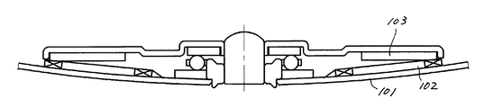
フレキシブルディスクドライブ(FDD)用のスピンドルモータには、回転軸と概ね直交する平面上に駆動用マグネットと駆動用コイルとを対向するように配置させて薄型化したいわゆるアキシャルギャップ型の偏平モータを好適に用いることができる。この偏平モータの従来例を図8に示す。 As a spindle motor for a flexible disk drive (FDD), a so-called axial gap type flat motor that is thinned by arranging a driving magnet and a driving coil so as to face each other on a plane substantially orthogonal to the rotation axis is suitable. Can be used. A conventional example of this flat motor is shown in FIG.
図8において、バックヨーク101上にはシャフト105を回転自由に支持する軸受106が固定され、この回転軸を中心にしてコイル102が同心状に複数配置されている。
シャフト105には、ロータヨーク104が固定されており、ロータヨーク104の内面にはコイル102と間隙Gを有して対向するようにマグネット103が固定されている。
この構成においてコイル102へ通電することによって、シャフト105,ロータヨーク104及びマグネット103からなるロータは、バックヨーク101に対して回転する。
In FIG. 8, a
A
In this configuration, when the
この従来の偏平モータの他の例として、本願出願人が出願した特許文献1や特許文献2に記載されたものがある。
ところで、近年、市場からの情報機器の小型化要求は一段と強く、FDDに搭載されるモータに対しても、その要求が及んでいる。特に、薄型化については顕著である。
上述した偏平モータをより薄型化する方法の1つとして、コイルとマグネットとの間の間隙Gを可能な限り小さくすることが追求されている。
By the way, in recent years, the demand for downsizing of information equipment from the market has become stronger, and the demand has also reached the motor mounted on the FDD. In particular, the reduction in thickness is remarkable.
As one of the methods for making the above flat motor thinner, it has been pursued to make the gap G between the coil and the magnet as small as possible.
モータを薄型化しつつ動作効率上げるためには、マグネットの材料として、強い磁力を発揮するNd−Fe−B(ネオジウム−鉄−ボロン)系等の希土類マグネットが用いられる。
そのため、図9に示すように、バックヨーク101がマグネット103に吸引され、そのマグネット103側に向かって変形する。
従って、コイル102とマグネット103との間隙Gは、バックヨーク101の外周側で狭くなり、場合によっては当図のように間隙がなくなり両者が接触してしまうという状態が発生していた。
In order to increase the operation efficiency while reducing the thickness of the motor, a rare earth magnet such as an Nd—Fe—B (neodymium-iron-boron) system that exhibits a strong magnetic force is used as a magnet material.
Therefore, as shown in FIG. 9, the
Accordingly, the gap G between the
これを解決するために、本願出願人は、上述した特許文献1において、バックヨークを回転中心から遠ざかるに従ってマグネットから離れるように椀状に変形させた偏平モータを提案する一方、特許文献2において、バックヨークの軸受取り付け部とその外周側のコイル取り付け部との境界に屈曲部を設け、コイル取り付け部をマグネットから離れる方向に傾斜させる形状にした偏平モータを提案している。
これらの偏平モータによれば、間隙をより小さくすることができ、モータの薄型化が効果的に可能となる。
In order to solve this, the applicant of the present application proposes a flat motor in which the back yoke is deformed in a bowl shape so as to be separated from the magnet as it moves away from the rotation center in Patent Document 1 described above. A flat motor has been proposed in which a bent portion is provided at the boundary between the bearing mounting portion of the back yoke and the coil mounting portion on the outer peripheral side, and the coil mounting portion is inclined in a direction away from the magnet.
According to these flat motors, the gap can be further reduced, and the motor can be effectively reduced in thickness.
しかしながら、バックヨークに、モータを駆動させるための電子部品が半田付けされていたり、また、それらの電子部品の電気的接続のために銅箔パターンが印刷により形成しなければならない場合があり、これらの場合に、予め変形させた非平面のバックヨークに電子部品を半田付けしたり銅箔パターンを印刷したりするのは、極めて難しく、生産性の向上に限界があった。 However, there are cases where electronic parts for driving the motor are soldered to the back yoke, or a copper foil pattern must be formed by printing for electrical connection of these electronic parts. In this case, it is extremely difficult to solder an electronic component or print a copper foil pattern on a non-planar back yoke deformed in advance, and there is a limit to improvement in productivity.
また、平面状のバックヨークに電子部品を半田付けしたり銅箔パターンを印刷した後にこれを変形させると、この変形によって加えられる力によって、電子部品や銅箔パターンが破損し、高い信頼性が得られない可能性があった。 In addition, if an electronic component is soldered on a flat back yoke or a copper foil pattern is printed and then deformed, the force applied by the deformation damages the electronic component or the copper foil pattern, resulting in high reliability. There was a possibility that it could not be obtained.
そこで、本発明が解決しようとする課題は、生産性向上が可能で、高い信頼性が得られ、更なる薄型化が可能な偏平モータを提供することにある。 Therefore, the problem to be solved by the present invention is to provide a flat motor capable of improving productivity, obtaining high reliability, and capable of further thinning.
上記の課題を解決するために、本願発明は手段として次の構成を有する。
即ち、請求項1に係る発明は、平面上に複数の駆動コイル(2)を配置したステータヨーク(1)を有するステータ(51)と、前記駆動コイル(2)に対向するように環状のマグネット(3,3A〜3D)を配置したロータヨーク(4,4B,4D)を有し前記ステータ(51)に対して回転するロータ(52)と、を備え、前記マグネット(3,3A〜3D)の前記駆動コイル(2)と対向する面(3a,3Aa〜3Da)に、回転中心から遠ざかるに従って前記駆動コイル(2)から離れる間隙拡大部(3Aa2,3Ca2)を設けて成ることを特徴とする偏平モータ(55)である。
In order to solve the above problems, the present invention has the following configuration as means.
That is, the invention according to claim 1 is a stator (51) having a stator yoke (1) in which a plurality of drive coils (2) are arranged on a plane, and an annular magnet so as to face the drive coil (2). A rotor yoke (4, 4B, 4D) in which (3, 3A to 3D) is disposed, and a rotor (52) that rotates relative to the stator (51), and the magnet (3, 3A to 3D) A flat surface characterized in that gap expansion portions (3Aa2, 3Ca2) that move away from the drive coil (2) as they move away from the center of rotation are provided on the surfaces (3a, 3Aa-3Da) facing the drive coil (2). It is a motor (55).
本発明によれば、生産性に優れ、信頼性が高く、より薄型にできるという効果を奏する。 According to the present invention, the productivity is excellent, the reliability is high, and the thickness can be reduced.
本発明の実施の形態を、好ましい実施例により図1〜図7を用いて説明する。
図1は、本発明の偏平モータの実施例を示す断面図であり、
図2は、本発明の偏平モータの実施例を説明する断面図であり、
図3は、本発明の偏平モータの第1の変形例を説明する要部断面図であり、
図4は、本発明の偏平モータの第2の変形例を説明する要部断面図であり、
図5は、本発明の偏平モータの第3の変形例を説明する要部断面図であり、
図6は、本発明の偏平モータの第4の変形例を説明する要部断面図であり、
図7は、本発明の偏平モータの実施例における外観を示す斜視図である。
The preferred embodiments of the present invention will be described with reference to FIGS.
FIG. 1 is a cross-sectional view showing an embodiment of the flat motor of the present invention,
FIG. 2 is a sectional view for explaining an embodiment of the flat motor of the present invention.
FIG. 3 is a cross-sectional view of a main part for explaining a first modification of the flat motor of the present invention.
FIG. 4 is a cross-sectional view of a main part for explaining a second modification of the flat motor of the present invention.
FIG. 5 is a cross-sectional view of an essential part for explaining a third modification of the flat motor of the present invention.
FIG. 6 is a cross-sectional view of a main part for explaining a fourth modification of the flat motor of the present invention.
FIG. 7 is a perspective view showing the appearance of an embodiment of the flat motor of the present invention.
実施例の偏平モータ55の外観を図7に示し、その詳細を図1,図2を用いて以下に説明する。
この偏平モータ55は、ステータヨークであるバックヨーク1と、これに固定された軸受6及びコイル2とを有するステータ51と、シャフト5,これに固定されたロータヨーク4及びロータヨーク4に固定されたマグネット3を有するロータ52とを備えている。
The external appearance of the flat motor 55 of an Example is shown in FIG. 7, and the detail is demonstrated below using FIG. 1, FIG.
The flat motor 55 includes a
バックヨーク1は、平板状であり、珪素鋼鈑等の軟質磁性材料からなる。
そのほぼ中央にはシャフト5を軸支する軸受6が固定されている。
バックヨーク1の一面には、銅箔の回路パターン1aが形成され、その回路パターン1aの表面は絶縁処理されている。
回路パターン1a上には、軸受6の軸を中心とした同心状に複数のコイル2が配置されている。
The back yoke 1 has a flat plate shape and is made of a soft magnetic material such as a silicon steel plate.
A
A copper foil circuit pattern 1a is formed on one surface of the back yoke 1, and the surface of the circuit pattern 1a is insulated.
On the circuit pattern 1a, a plurality of
軸受6に軸支されるシャフト5には、略円盤状のロータヨーク4が固定されている。このロータヨーク4は、亜鉛メッキ鋼鈑をプレス成形することにより形成される。
ロータヨーク4の内側面には、コイル2と所定の間隙G(G1〜G2)を有して対向するように平たい環状のマグネット3が固着されている。この間隙Gについては、詳細を後述する。マグネット3は、Nd−Fe−B(ネオジウム−鉄−ボロン)系希土類硬質磁性材料で形成される。
この構成で、コイル2に所定の方法で電流が付与されることで、ロータ52はステータ51に対して回転する。
A substantially disc-
A flat
With this configuration, the
次に、マグネット3とコイル2との間隙G(G1〜G2)について詳述する。
実施例におけるマグネット3は、図1に示すように、断面が台形形状になっている。
具体的には、軸方向の厚さにおいて外周側の厚さの方が内周側の厚さより薄く、コイル2と対向する対向面3aが外周側に向かうに従ってコイル2から離れる方向に傾斜した形状の台形断面とされている。このマグネット3の内周側及び外周側におけるコイル2との間隙Gは、G1及びG2である。
そして、このマグネット3の外周側の厚さと内周側の厚さとの差(以下、厚み差と称する)を図1ではΔgとして示している。
Next, the gap G (G1 to G2) between the
The
Specifically, in the axial thickness, the outer peripheral thickness is thinner than the inner peripheral thickness, and the opposing surface 3a facing the
And the difference (henceforth thickness difference) of the thickness of the outer peripheral side of this
このため、モータを組み立てた状態で、図2に示すように、マグネット3の強い吸引力により、ロータヨーク4とバックヨーク1とは互いに近づく方向に変形するものの、マグネット3の対向面3aが傾斜して厚み差Δg(図1参照)を有していることにより、最も変形量の多い外周側でも僅かな隙間g1を残してマグネット3(またはロータヨーク4)と、コイル2とが接触してしまうことがない。
Therefore, in the assembled state of the motor, as shown in FIG. 2, the
この厚み差Δgは、マグネットの磁力や各部位の寸法等、モータの仕様毎に最適となるように設定することができるが、一例として示せば、マグネット3の外径φ39.5mmに対して概して0.1mm〜0.2mm程度となるものである。 This thickness difference Δg can be set so as to be optimal for each motor specification, such as the magnetic force of the magnet and the size of each part. It is about 0.1 mm to 0.2 mm.
本発明は、マグネットの磁気吸引がないとした状態において、マグネットのコイルと対向する面に、マグネットとコイルとの間隔が外周に向かって広くなる間隙拡大部を設けたものであればよい。この間隙拡大部は、傾斜面であってもよく、その傾斜面が階段状になっていてもよく、また、コイルと平行に対向する面が階段状になって間隙が拡大する部分であってもよい。また、コイルと平行に対向する部分が一部分ある傾斜面でもよい。傾斜面は平面でも曲面でもよい。
以下、変形例のいくつかを説明するが、上述の実施例や以下の変形例に限るものではなく、要旨を逸脱しない範囲において種々の変形が可能である。
In the present invention, it is only necessary to provide a gap expanding portion on the surface of the magnet that faces the coil in a state where there is no magnetic attraction of the magnet so that the gap between the magnet and the coil becomes wider toward the outer periphery. The gap enlarging portion may be an inclined surface, the inclined surface may be stepped, and the surface facing in parallel with the coil is stepped to expand the gap. Also good. Further, it may be an inclined surface with a portion facing in parallel with the coil. The inclined surface may be a flat surface or a curved surface.
Hereinafter, some of the modifications will be described. However, the present invention is not limited to the above-described embodiments and the following modifications, and various modifications can be made without departing from the scope of the invention.
第1の変形例を図3に示す。
この例は、マグネット3Aの対向面3Aaが、磁気吸引がないとした場合に、コイルと一定の間隙を有する内周部3Aa1と、コイル2から離れる方向に傾斜する傾斜部3Aa2とを有するものである。
A first modification is shown in FIG.
In this example, the opposing surface 3Aa of the magnet 3A has an inner peripheral portion 3Aa1 having a certain gap from the coil and an inclined portion 3Aa2 inclined in a direction away from the
従って、この内周部3Aa1は、コイル2のマグネット3Aと対向する対向面2aが軸CLと直交する面で形成されていれば、それと平行な面となる。
この形状のマグネット3Aは、マグネット単体で保管する場合に安定して重ねられ、また、内周部3Aa1と傾斜部3Aa2との境界線3Acが明瞭に形成されるので、表裏の判別が容易となるものである。
Therefore, if the opposing surface 2a facing the magnet 3A of the
When the magnet 3A having this shape is stored as a single magnet, the magnet 3A is stably stacked, and the boundary line 3Ac between the inner peripheral portion 3Aa1 and the inclined portion 3Aa2 is clearly formed, so that the front and back can be easily distinguished. Is.
内周部3Aa1を形成したことで、内周部が無いマグネット3を用いた場合より、間隙は広くせざるを得ずトルク定数が若干低下するものの、トルクに寄与するのはマグネットの内周側よりも外周側であるから、顕著なトルク低下とはならない。
実用上は、以下の(式1)の範囲で設定すればマグネット3と同等のトルク性能が発揮されるので望ましい。
即ち、境界線3Acの半径r2は、マグネット3Aの内径r1と外径r3に対して、
r2≦r1+0.7×(r3−r1)…(式1)
の範囲に設定するのが望ましい。
Since the inner peripheral portion 3Aa1 is formed, the gap must be made wider than when the
Practically, it is desirable that the torque performance equivalent to that of the
That is, the radius r2 of the boundary line 3Ac is smaller than the inner diameter r1 and the outer diameter r3 of the magnet 3A.
r2 ≦ r1 + 0.7 × (r3−r1) (Formula 1)
It is desirable to set the range.
第2の変形例を図4に示す。
この例は、マグネット3Bの対向面3Baと、その反対側の面3Bbとを傾斜面とした例である。
従って、ロータヨーク4Bも面3Bbに合わせて外周側をコイル2側に近づく形状に形成してあり、外周部でのモータ全体の厚さを薄くしたい場合に好適である。
この形状のマグネット3Bは、対向面3Baとその反対側の面3Bbの傾斜量Δg1(図4参照)を同じにした場合、取り付けにおいて表裏の方向判別が不要となり作業が極めて容易となる。
A second modification is shown in FIG.
In this example, the opposing surface 3Ba of the
Therefore, the
When the inclination amount Δg1 (see FIG. 4) of the opposing surface 3Ba and the opposite surface 3Bb is the same, the
第3の変形例を図5に示す。
この例は、マグネット3Cを、第2の変形例のマグネット3Bに対して第1の変形例のように、内周部3Ca1と傾斜部3Ca2とを、対向面3Caとその反対側の面3Cbの両方に設けたマグネットとした例である。
この変形例も、第2の変形例と同様に、ロータヨーク4Cも傾斜部3Cb2に合わせて外周側をコイル2側に近づける形状に形成しているので、外周部側のモータ全体の厚さを薄くしたい場合に好適である。
A third modification is shown in FIG.
In this example, the
In this modified example, as in the second modified example, the rotor yoke 4C is also formed in a shape that brings the outer peripheral side closer to the
第4の変形例を図6に示す。
この例は、マグネット3Dの厚みを一定にし、コイル2との間隙が外周側でΔg2だけ広がるように、ロータヨーク4Dをコイル2から離れる方向にΔg2変形させると共に、それに沿った形状にマグネット3Dを形成したものである。従って、マグネット3Dの表面形状は、円錐表面の一部となる。
この変形例は、回転中心近傍のモータの厚みを薄くしたい場合に好適である。
マグネット3Dを、可撓性を有する材料(例えばゴム磁石)で形成すれば、ロータヨーク4Dに沿って変形させて固定できるので、好ましい。
A fourth modification is shown in FIG.
In this example, the thickness of the
This modification is suitable when it is desired to reduce the thickness of the motor near the rotation center.
If the
上述した実施例及び変形例は、シャフトが回転するいわゆる軸回転型の偏平モータについて説明したが、バックヨーク側にシャフトを固定し、ロータヨーク側にこのシャフトを挿通する軸受を備え、この軸受を介してロータが回転するいわゆる軸固定型の偏平モータであってもよいのは言うまでもない。 In the above-described embodiments and modifications, the so-called shaft rotation type flat motor in which the shaft rotates has been described. However, the shaft is fixed on the back yoke side, and the bearing is inserted through the shaft on the rotor yoke side. Needless to say, it may be a so-called shaft-fixed flat motor in which the rotor rotates.
1 バックヨーク(ステータヨーク)
1a 回路パターン
2 コイル
2a 対向面
3,3A〜3D マグネット
3a (3Aa〜3Da) 対向面
3Aa1,3Ca1 内周部
3Aa2,3Ca2 傾斜部(間隙拡大部)
3Ac 境界線
3Bb,3Cb (反対側の)面
(3A〜3D) マグネット
4,4B,4D ロータヨーク
5 シャフト
6 軸受
51 ステータ
52 ロータ
55 偏平モータ
G,G1,G2,g1 間隙
Δg 厚み差
Δg1,Δg2 傾斜量
1 Back yoke (stator yoke)
DESCRIPTION OF SYMBOLS
3Ac Boundary lines 3Bb, 3Cb (opposite side) surfaces (3A-3D)
Claims (1)
前記駆動コイルに対向するように環状のマグネットを配置したロータヨークを有し前記ステータに対して回転するロータとを備え、
前記マグネットの前記駆動コイルと対向する面に、回転中心から遠ざかるに従って前記コイルから離れる間隙拡大部を設けて成ること特徴とする偏平モータ。 A stator having a stator yoke in which a plurality of drive coils are arranged on a plane;
A rotor yoke having an annular magnet disposed so as to face the drive coil, and a rotor that rotates relative to the stator;
A flat motor having a gap expanding portion that is separated from the coil as the distance from the rotation center increases on a surface of the magnet facing the drive coil.
Priority Applications (1)
| Application Number | Priority Date | Filing Date | Title |
|---|---|---|---|
| JP2004178198A JP4342380B2 (en) | 2004-06-16 | 2004-06-16 | Flat motor |
Applications Claiming Priority (1)
| Application Number | Priority Date | Filing Date | Title |
|---|---|---|---|
| JP2004178198A JP4342380B2 (en) | 2004-06-16 | 2004-06-16 | Flat motor |
Publications (2)
| Publication Number | Publication Date |
|---|---|
| JP2006006003A true JP2006006003A (en) | 2006-01-05 |
| JP4342380B2 JP4342380B2 (en) | 2009-10-14 |
Family
ID=35773929
Family Applications (1)
| Application Number | Title | Priority Date | Filing Date |
|---|---|---|---|
| JP2004178198A Expired - Fee Related JP4342380B2 (en) | 2004-06-16 | 2004-06-16 | Flat motor |
Country Status (1)
| Country | Link |
|---|---|
| JP (1) | JP4342380B2 (en) |
Cited By (6)
| Publication number | Priority date | Publication date | Assignee | Title |
|---|---|---|---|---|
| JP2007330025A (en) * | 2006-06-07 | 2007-12-20 | Daikin Ind Ltd | Motor |
| JP2008295284A (en) * | 2007-04-26 | 2008-12-04 | Seiko Epson Corp | Brushless electrical machine |
| JP2011125213A (en) * | 2009-12-08 | 2011-06-23 | Siemens Ag | Apparatus for ensuring air gap in electric machine |
| US8319469B2 (en) | 2007-04-26 | 2012-11-27 | Seiko Epson Corporation | Brushless electric machine |
| JP2020522970A (en) * | 2017-06-05 | 2020-07-30 | イー−サーキット モーターズ, インコーポレイテッド | Prestrained rotor for control of magnet/stator clearance in axial flux machines |
| CN114731078A (en) * | 2019-11-12 | 2022-07-08 | 电路电机有限公司 | Rotor assembly for axial flux machine |
Families Citing this family (1)
| Publication number | Priority date | Publication date | Assignee | Title |
|---|---|---|---|---|
| CN105006898B (en) * | 2015-07-30 | 2017-10-03 | 浙江西子富沃德电机有限公司 | A kind of disc-type permanent magnet motor and its magnet steel |
-
2004
- 2004-06-16 JP JP2004178198A patent/JP4342380B2/en not_active Expired - Fee Related
Cited By (8)
| Publication number | Priority date | Publication date | Assignee | Title |
|---|---|---|---|---|
| JP2007330025A (en) * | 2006-06-07 | 2007-12-20 | Daikin Ind Ltd | Motor |
| JP2008295284A (en) * | 2007-04-26 | 2008-12-04 | Seiko Epson Corp | Brushless electrical machine |
| US8319469B2 (en) | 2007-04-26 | 2012-11-27 | Seiko Epson Corporation | Brushless electric machine |
| US8581459B2 (en) | 2007-04-26 | 2013-11-12 | Seiko Epson Corporation | Brushless electric machine |
| JP2011125213A (en) * | 2009-12-08 | 2011-06-23 | Siemens Ag | Apparatus for ensuring air gap in electric machine |
| JP2020522970A (en) * | 2017-06-05 | 2020-07-30 | イー−サーキット モーターズ, インコーポレイテッド | Prestrained rotor for control of magnet/stator clearance in axial flux machines |
| JP7369382B2 (en) | 2017-06-05 | 2023-10-26 | イー-サーキット モーターズ, インコーポレイテッド | Prestrained rotor for magnet/stator gap control in axial flux machines |
| CN114731078A (en) * | 2019-11-12 | 2022-07-08 | 电路电机有限公司 | Rotor assembly for axial flux machine |
Also Published As
| Publication number | Publication date |
|---|---|
| JP4342380B2 (en) | 2009-10-14 |
Similar Documents
| Publication | Publication Date | Title |
|---|---|---|
| US7321178B2 (en) | Spindle motor | |
| US6346759B1 (en) | Stator structure of highspeed motor | |
| JP2004015906A (en) | Permanent magnet motor | |
| US8878416B2 (en) | Stator core and motor device including the same | |
| US20060255677A1 (en) | Magnetic member, motor device, magnetizing method and storage device | |
| JP2012217320A (en) | Permanent magnet motor | |
| JP4342380B2 (en) | Flat motor | |
| EP1202430A1 (en) | Brushless motor | |
| US20050006965A1 (en) | Rotational driving device | |
| JP2001061240A (en) | Motor that rotates in one direction | |
| JPH07245926A (en) | Brushless motor | |
| JP5311020B2 (en) | Spindle motor | |
| JP4959389B2 (en) | motor | |
| JP2010035268A (en) | Axial gap type motor | |
| JP2004289881A (en) | Motor and recording medium driving gear | |
| JP2002204542A (en) | Permanent magnet for axial direction gap type motor, magnetizing method and apparatus for the magnet, axial direction gap type motor provided with the magnet | |
| JPH09285092A (en) | Thin dc brushless motor | |
| JP2006325365A (en) | Stator partially formed of non-magnetic body and brushless motor using same | |
| JP2009268168A (en) | Motor and method of manufacturing the same | |
| JPH07123672A (en) | Motor | |
| JP2005080344A (en) | Permanent magnet type rotor | |
| JP2005253164A (en) | Motor | |
| JP2002204542A5 (en) | ||
| JP5163341B2 (en) | Axial gap type motor | |
| JP2003299266A (en) | Small winding core for high performance rotating machine |
Legal Events
| Date | Code | Title | Description |
|---|---|---|---|
| A621 | Written request for application examination |
Free format text: JAPANESE INTERMEDIATE CODE: A621 Effective date: 20060630 |
|
| A711 | Notification of change in applicant |
Free format text: JAPANESE INTERMEDIATE CODE: A711 Effective date: 20080401 |
|
| RD02 | Notification of acceptance of power of attorney |
Free format text: JAPANESE INTERMEDIATE CODE: A7422 Effective date: 20080428 |
|
| A977 | Report on retrieval |
Free format text: JAPANESE INTERMEDIATE CODE: A971007 Effective date: 20090415 |
|
| A131 | Notification of reasons for refusal |
Free format text: JAPANESE INTERMEDIATE CODE: A131 Effective date: 20090421 |
|
| A521 | Written amendment |
Free format text: JAPANESE INTERMEDIATE CODE: A523 Effective date: 20090528 |
|
| TRDD | Decision of grant or rejection written | ||
| A01 | Written decision to grant a patent or to grant a registration (utility model) |
Free format text: JAPANESE INTERMEDIATE CODE: A01 Effective date: 20090630 |
|
| A01 | Written decision to grant a patent or to grant a registration (utility model) |
Free format text: JAPANESE INTERMEDIATE CODE: A01 |
|
| A61 | First payment of annual fees (during grant procedure) |
Free format text: JAPANESE INTERMEDIATE CODE: A61 Effective date: 20090707 |
|
| FPAY | Renewal fee payment (event date is renewal date of database) |
Free format text: PAYMENT UNTIL: 20120717 Year of fee payment: 3 |
|
| R150 | Certificate of patent or registration of utility model |
Free format text: JAPANESE INTERMEDIATE CODE: R150 |
|
| FPAY | Renewal fee payment (event date is renewal date of database) |
Free format text: PAYMENT UNTIL: 20130717 Year of fee payment: 4 |
|
| S533 | Written request for registration of change of name |
Free format text: JAPANESE INTERMEDIATE CODE: R313533 |
|
| R350 | Written notification of registration of transfer |
Free format text: JAPANESE INTERMEDIATE CODE: R350 |
|
| R250 | Receipt of annual fees |
Free format text: JAPANESE INTERMEDIATE CODE: R250 |
|
| R250 | Receipt of annual fees |
Free format text: JAPANESE INTERMEDIATE CODE: R250 |
|
| R250 | Receipt of annual fees |
Free format text: JAPANESE INTERMEDIATE CODE: R250 |
|
| LAPS | Cancellation because of no payment of annual fees |