JP2005534979A - Fine particle transfer film with improved bead carrier - Google Patents
Fine particle transfer film with improved bead carrier Download PDFInfo
- Publication number
- JP2005534979A JP2005534979A JP2004525995A JP2004525995A JP2005534979A JP 2005534979 A JP2005534979 A JP 2005534979A JP 2004525995 A JP2004525995 A JP 2004525995A JP 2004525995 A JP2004525995 A JP 2004525995A JP 2005534979 A JP2005534979 A JP 2005534979A
- Authority
- JP
- Japan
- Prior art keywords
- carrier
- temporary
- beads
- layer
- bead
- Prior art date
- Legal status (The legal status is an assumption and is not a legal conclusion. Google has not performed a legal analysis and makes no representation as to the accuracy of the status listed.)
- Withdrawn
Links
Images


Classifications
-
- B—PERFORMING OPERATIONS; TRANSPORTING
- B44—DECORATIVE ARTS
- B44C—PRODUCING DECORATIVE EFFECTS; MOSAICS; TARSIA WORK; PAPERHANGING
- B44C1/00—Processes, not specifically provided for elsewhere, for producing decorative surface effects
- B44C1/16—Processes, not specifically provided for elsewhere, for producing decorative surface effects for applying transfer pictures or the like
- B44C1/165—Processes, not specifically provided for elsewhere, for producing decorative surface effects for applying transfer pictures or the like for decalcomanias; sheet material therefor
- B44C1/17—Dry transfer
- B44C1/1712—Decalcomanias applied under heat and pressure, e.g. provided with a heat activable adhesive
- B44C1/1716—Decalcomanias provided with a particular decorative layer, e.g. specially adapted to allow the formation of a metallic or dyestuff layer on a substrate unsuitable for direct deposition
-
- G—PHYSICS
- G02—OPTICS
- G02B—OPTICAL ELEMENTS, SYSTEMS OR APPARATUS
- G02B5/00—Optical elements other than lenses
- G02B5/12—Reflex reflectors
- G02B5/126—Reflex reflectors including curved refracting surface
- G02B5/128—Reflex reflectors including curved refracting surface transparent spheres being embedded in matrix
-
- B—PERFORMING OPERATIONS; TRANSPORTING
- B29—WORKING OF PLASTICS; WORKING OF SUBSTANCES IN A PLASTIC STATE IN GENERAL
- B29D—PRODUCING PARTICULAR ARTICLES FROM PLASTICS OR FROM SUBSTANCES IN A PLASTIC STATE
- B29D11/00—Producing optical elements, e.g. lenses or prisms
-
- B—PERFORMING OPERATIONS; TRANSPORTING
- B29—WORKING OF PLASTICS; WORKING OF SUBSTANCES IN A PLASTIC STATE IN GENERAL
- B29D—PRODUCING PARTICULAR ARTICLES FROM PLASTICS OR FROM SUBSTANCES IN A PLASTIC STATE
- B29D11/00—Producing optical elements, e.g. lenses or prisms
- B29D11/00605—Production of reflex reflectors
- B29D11/00615—Production of reflex reflectors moulded by partially embedding reflective elements, e.g. glass beads, into the surface of a support, e.g. to make prefabricated road markings
-
- Y—GENERAL TAGGING OF NEW TECHNOLOGICAL DEVELOPMENTS; GENERAL TAGGING OF CROSS-SECTIONAL TECHNOLOGIES SPANNING OVER SEVERAL SECTIONS OF THE IPC; TECHNICAL SUBJECTS COVERED BY FORMER USPC CROSS-REFERENCE ART COLLECTIONS [XRACs] AND DIGESTS
- Y10—TECHNICAL SUBJECTS COVERED BY FORMER USPC
- Y10T—TECHNICAL SUBJECTS COVERED BY FORMER US CLASSIFICATION
- Y10T428/00—Stock material or miscellaneous articles
- Y10T428/25—Web or sheet containing structurally defined element or component and including a second component containing structurally defined particles
-
- Y—GENERAL TAGGING OF NEW TECHNOLOGICAL DEVELOPMENTS; GENERAL TAGGING OF CROSS-SECTIONAL TECHNOLOGIES SPANNING OVER SEVERAL SECTIONS OF THE IPC; TECHNICAL SUBJECTS COVERED BY FORMER USPC CROSS-REFERENCE ART COLLECTIONS [XRACs] AND DIGESTS
- Y10—TECHNICAL SUBJECTS COVERED BY FORMER USPC
- Y10T—TECHNICAL SUBJECTS COVERED BY FORMER US CLASSIFICATION
- Y10T428/00—Stock material or miscellaneous articles
- Y10T428/28—Web or sheet containing structurally defined element or component and having an adhesive outermost layer
Landscapes
- Physics & Mathematics (AREA)
- Engineering & Computer Science (AREA)
- General Physics & Mathematics (AREA)
- Ophthalmology & Optometry (AREA)
- Mechanical Engineering (AREA)
- Manufacturing & Machinery (AREA)
- Health & Medical Sciences (AREA)
- Optics & Photonics (AREA)
- Optical Elements Other Than Lenses (AREA)
- Laminated Bodies (AREA)
- Adhesives Or Adhesive Processes (AREA)
- Adhesive Tapes (AREA)
- Decoration Of Textiles (AREA)
Abstract
光学ビーズを基材に転写するよう構成された転写フィルムが開示されている。転写フィルムは、光学ビーズ(68)と、光学ビーズを保持する一時ビーズキャリア層(62)と、光学ビーズを基材に永続的に接合するよう構成された光学接着層(74)とを含んでいる。一時ビーズキャリア層は、キャリアバッキング(64)と、高温で基材への適用中、ビーズを一時的に保持する耐熱キャリアコーティング(66)とを含んでいる。最初に軟化してビーズを保持してから、硬化または熱硬化(架橋による等)して、ビーズの基材への転写中にキャリアコーティングが軟化するのを防ぐようにキャリアコーティングは形成されている。A transfer film configured to transfer optical beads to a substrate is disclosed. The transfer film includes optical beads (68), a temporary bead carrier layer (62) that holds the optical beads, and an optical adhesive layer (74) configured to permanently bond the optical beads to the substrate. Yes. The temporary bead carrier layer includes a carrier backing (64) and a heat resistant carrier coating (66) that temporarily holds the beads during application to the substrate at elevated temperatures. The carrier coating is formed to first soften and hold the beads, and then harden or heat cure (such as by cross-linking) to prevent the carrier coating from softening during transfer of the beads to the substrate. .
Description
本発明は、微粒子を基材に転写するのに用いる転写フィルムに関する。特に、本発明は、透明ビーズまたはその他微粒子の層を布帛のような基材に転写するのに用いる転写フィルム、転写フィルムの製造および使用方法に関する。本発明は、透明ビーズの層がパターン化される再帰反射性転写フィルムに特に有用である。 The present invention relates to a transfer film used for transferring fine particles to a substrate. In particular, the present invention relates to a transfer film used for transferring a layer of transparent beads or other fine particles to a substrate such as a fabric, and a method for producing and using the transfer film. The present invention is particularly useful for retroreflective transfer films in which a layer of transparent beads is patterned.
再帰反射性シートは、交通標識、舗装標識、車両および衣類といった様々な対象物の夜間の顕著性を増大させるのに一般的に用いられている。多くの再帰反射性シートは、シートにおける再帰反射要素としてガラスビースを用いている。ビーズは、ビーズを熱活性接着剤により接着する熱プレスを用いて最終対象物に転写される。接着剤とビーズは、ビーズと、接着層と、接着剤をカバーする任意の剥離ライナと、基材に配置する前にビーズを保持する一時ビーズキャリアとを含む多層フィルムに分配することができる。他のある具体例においては、ビーズ同士を結合およびビーズを接着剤に結合するよう構成されたビーズボンド層、そして反射性を改善するためにビーズの下部にアルミニウム反射層のようなその他の層を用いてもよい。 Retroreflective sheets are commonly used to increase nighttime saliency of various objects such as traffic signs, pavement signs, vehicles and clothing. Many retroreflective sheets use glass beads as retroreflective elements in the sheet. The beads are transferred to the final object using a hot press that bonds the beads with a thermally activated adhesive. The adhesive and beads can be distributed in a multilayer film comprising beads, an adhesive layer, an optional release liner that covers the adhesive, and a temporary bead carrier that holds the beads prior to placement on the substrate. In some other embodiments, a bead bond layer configured to bond the beads together and bond the beads to the adhesive, and other layers such as an aluminum reflective layer at the bottom of the bead to improve reflectivity. It may be used.
特許文献1(ベルグ(Berg))には、かかるシートを製造する一つの方法が開示されている。その方法は、非反射ガラスビーズを一時的ビーズキャリアに取り付けることから始まる。一時ビーズキャリアは、紙か、熱により軟化可能な熱可塑性ポリマー、たいていはポリエチレンのコーティングを有するポリマーシートのいずれかとすることができる。ガラスビーズは、軟化したポリマーに、加熱の際に部分的に沈む。続いて、キャリアが冷やされ、基材に取り付けられるまでビーズを保持する。後の処理工程後、一時ビーズキャリアをラミネートから剥がしてビーズを露わにする。 Patent Document 1 (Berg) discloses one method for producing such a sheet. The method begins with attaching non-reflective glass beads to a temporary bead carrier. The temporary bead carrier can be either paper or a polymer sheet with a heat-softening thermoplastic polymer, usually a polyethylene coating. The glass beads partially sink into the softened polymer upon heating. Subsequently, the beads are held until the carrier is cooled and attached to the substrate. After subsequent processing steps, the temporary bead carrier is peeled off the laminate to expose the beads.
シートおよび最終対象物にあるビーズは、レタリングやロゴといった画像やインディシアのパターンで適用してよい。ビーズを衣類に適用するときはパターンは非常に一般的なものである。かかるパターンを形成する一つの方法は、ビーズの均一な層を有する再帰反射シートを一時ビーズキャリアに沿って広げることから始めて、接着層でカバーするものである。ナイフを有するプロッタを用いて、シート片からパターンをキスカットする。レーザーカットまたはダイカットを用いてもよい。接着層およびビーズを貫いてカットされるが、一時ビーズキャリアまではカットされないようにキスカットを行う。「ウィード」と呼ばれることの多い廃棄材料を除去すると、一時キャリアにビーズの所望のパターンと接着剤だけが残る。除去したウィードには、ビーズと接着剤、さらに接着剤剥離ライナのような他の層が含まれている。一時ビーズキャリアは、通常、元のサイズと形状を保持しており、プロッタによりカットされなかったため、ビーズのパターンを保持する。 The beads on the sheet and final object may be applied in an image or lettering pattern such as lettering or logo. The pattern is very common when applying beads to clothing. One way to form such a pattern is to start with spreading a retroreflective sheet having a uniform layer of beads along the temporary bead carrier and cover it with an adhesive layer. Using a plotter with a knife, kiss cut the pattern from the sheet piece. Laser cut or die cut may be used. Kiss cutting is performed so as to cut through the adhesive layer and the beads, but not to the temporary bead carrier. Removal of waste material, often referred to as “weed”, leaves only the desired pattern of beads and adhesive on the temporary carrier. The removed weed contains beads and adhesive, as well as other layers such as an adhesive release liner. Temporary bead carriers usually retain their original size and shape and are not cut by the plotter, thus retaining the bead pattern.
形成されたパターンの衣類や布帛といった基材への取り付けは、以下の工程により行うことができる。第1に、パターンを基材の所望の位置に配置して、熱活性接着剤を基材に対向させ、一時ビーズキャリア面を外側に向ける。第2に、熱プレスを用いて接着剤を活性化させて、層を併せてプレスする。冷却後、一時ビーズキャリアを除去すると、基材に取り付けられた再帰反射性インディシアが残る。
これらの従来のシートのカットおよびラミネーションプロセス中には2つの問題が起こり得る。第1は、プロッタによる層のカット動作によって、転写フィルムが一時ビーズキャリアから早期に分離してしまい、後の適用工程での取扱いが非常に難しくなってしまうことである。第2に、一時ビーズキャリアに用いる熱可塑性コーティング材料が、部分的に溶融して、ラミネーション工程中に基材に転写されて、一時ビーズキャリアを完全に除去することが困難または不可能となり、所望の再帰反射性パターンを囲む領域が残ってしまうことである。従って、これらの問題を解消する改善が求められている。 Two problems can occur during the cutting and lamination processes of these conventional sheets. The first is that the transfer film is separated from the temporary bead carrier at an early stage by the layer cutting operation by the plotter, and the handling in the subsequent application process becomes very difficult. Second, the thermoplastic coating material used for the temporary bead carrier is partially melted and transferred to the substrate during the lamination process, making it difficult or impossible to completely remove the temporary bead carrier, as desired. The region surrounding the retroreflective pattern remains. Therefore, there is a need for improvements that eliminate these problems.
本出願は、微粒子を基材に転写するべく構成された転写フィルムを開示している。ある具体例において、微粒子はビーズを含む。かかる具体例において、転写フィルムは、少なくとも以下の材料または層、すなわち、ビーズと、ビーズを保持する一時ビーズキャリアとを含む。一時ビーズキャリア層は、一般的に、基材への適用中、ビーズを一時的に保持する耐熱キャリアコーティング材料を含んでいる。最初に軟化してビーズを一時的に保持してから、硬化または熱硬化(架橋による等)して、ビーズの基材への転写中にキャリアコーティングが溶融するのを防ぐようにキャリアコーティングは形成されている。このキャリアコーティングは、紙やプラスチックフィルムのようなキャリアバッキングへ接着される。 This application discloses a transfer film configured to transfer fine particles to a substrate. In certain embodiments, the microparticles include beads. In such embodiments, the transfer film comprises at least the following materials or layers: beads and a temporary bead carrier that holds the beads. The temporary bead carrier layer generally includes a heat resistant carrier coating material that temporarily holds the beads during application to the substrate. The carrier coating is formed to soften first to temporarily hold the beads and then harden or heat cure (such as by crosslinking) to prevent the carrier coating from melting during the transfer of the beads to the substrate. Has been. This carrier coating is adhered to a carrier backing such as paper or plastic film.
たいていの具体例において、転写フィルムはまた、ビーズに適用された反射コーティングと、ビーズを基材に固定する接着剤と、ビーズを互いに、そして接着剤に固定するビーズボンド層とを含んでいる。好適な反射コーティングとしては、アルミニウムのような金属コーティングが挙げられる。好適なビーズボンド層としては、例えば、フェノール樹脂およびニトリルブタジエンゴム(NBR)が挙げられる。 In most embodiments, the transfer film also includes a reflective coating applied to the beads, an adhesive that secures the beads to the substrate, and a bead bond layer that secures the beads to each other and to the adhesive. Suitable reflective coatings include metal coatings such as aluminum. Suitable bead bond layers include, for example, phenolic resin and nitrile butadiene rubber (NBR).
ある実施形態においては、一時キャリア層のキャリアコーティングは、照射すると熱硬化性となる熱可塑性材料から形成される。例えば、熱硬化性キャリアコーティングは、熱可塑性材料を電子ビーム源に露光することにより形成することができる。上述した通り、キャリアコーティングは製造中熱可塑性で、ビーズが一時的にそこに固定されるが、ビーズを基材に適用する間露出したキャリアコーティングが基材に結合しないよう後には熱硬化性に変化するのが有利である。 In some embodiments, the carrier coating of the temporary carrier layer is formed from a thermoplastic material that becomes thermosetting upon irradiation. For example, a thermosetting carrier coating can be formed by exposing a thermoplastic material to an electron beam source. As noted above, the carrier coating is thermoplastic during manufacture, and the beads are temporarily secured thereto, but later become thermoset so that the exposed carrier coating does not bond to the substrate during application of the beads to the substrate. It is advantageous to change.
本明細書において、「熱硬化性」という用語は、高温、特に、ビーズまたはその他微粒子が基材に転写される適用温度まで昇温したときに大幅に軟化しない組成物のことを指す。大量の軟化とは、例えば、ビーズの基材への転写中に、組成物が基材に容易に、かつ著しく転写されるほど軟化することをいう。このように、通常の適用温度で基材に容易に、かつ著しく転写する材料は「熱硬化性」とは考えられない。有用な熱硬化性材料は、一般的に、元々熱可塑性の材料から形成される。すなわち、高温で繰り返し軟化されるが、本明細書に記載した架橋反応により熱硬化性へと変化する。 As used herein, the term “thermosetting” refers to a composition that does not soften significantly when elevated to high temperatures, particularly application temperatures at which beads or other particulates are transferred to a substrate. A large amount of softening means, for example, that the composition is softened easily and remarkably transferred to the substrate during the transfer of the beads to the substrate. Thus, materials that easily and significantly transfer to a substrate at normal application temperatures are not considered “thermosetting”. Useful thermoset materials are generally formed from originally thermoplastic materials. That is, although it is repeatedly softened at a high temperature, it changes to thermosetting by the crosslinking reaction described in this specification.
また、パターン形成プロセスによって、ビーズ層が一時ビーズキャリアから意図せずに剥がれないよう、ビーズはキャリアコーティングに十分に強固なボンドを形成するのが望ましい。この問題は、自動プロッタカッターを用いるときに特に顕著であるため、自動高度製造施設においては重要である。 It is also desirable that the beads form a sufficiently strong bond to the carrier coating so that the patterning process does not unintentionally peel the bead layer from the temporary bead carrier. This problem is particularly noticeable when using an automatic plotter cutter, and is therefore important in automated advanced manufacturing facilities.
接着層を用いて、布帛のような基材へビーズを永続的に接着させる。接着剤層はまた、例えば、熱可塑性接着組成物とすることもできる。接着組成物は異なる用途において異なるが、通常は、目的の基材に容易に接着して、ビーズ(またはビーズボンド層)を基材に対して耐久性のあるボンドを提供するようなものを選択するものとする。好適な接着剤としては、例えば、ポリエステル型熱可塑性ポリウレタンが挙げられる。 An adhesive layer is used to permanently adhere the beads to a substrate such as a fabric. The adhesive layer can also be, for example, a thermoplastic adhesive composition. Adhesive compositions vary in different applications, but are usually selected to easily adhere to the target substrate and provide a durable bond for the beads (or bead bond layer) to the substrate It shall be. Suitable adhesives include, for example, polyester type thermoplastic polyurethane.
本発明の構造に有用なビーズは、通常、光学ガラスビーズ、通常は、再帰反射性光学ビーズである。ビーズは様々なサイズおよび形状としてよいが、一般的には球状で、直径が約60〜120ミクロンである。非光学ビーズまたはその他微粒子材料も用いてよい。 The beads useful in the structure of the present invention are usually optical glass beads, usually retroreflective optical beads. The beads may be of various sizes and shapes, but are generally spherical and have a diameter of about 60-120 microns. Non-optical beads or other particulate materials may also be used.
さらに、微粒子転写フィルムの作成方法が開示されている。かかる方法の一つは、熱により軟化する熱可塑性層を提供して、光学ビーズのような微粒子材料を含浸させ、架橋させて高い軟化または分解温度を有する熱硬化性層を形成するものである。このように、熱可塑性材料は、架橋により熱硬化性となる。 Furthermore, a method for producing a fine particle transfer film is disclosed. One such method is to provide a heat-softening thermoplastic layer that is impregnated with a particulate material such as optical beads and crosslinked to form a thermosetting layer having a high softening or decomposition temperature. . Thus, the thermoplastic material becomes thermosetting by crosslinking.
上記概要は限定するためのものでもなく、例示の各実施形態または本開示内容のそれぞれの実施を説明することを意図するものではない。独占権が求められる本発明は、補正されてもよい、添付の全請求の範囲により定義される。 The above summary is not intended to be limiting and is not intended to describe each exemplary embodiment or each implementation of the present disclosure. The invention for which exclusivity is sought is defined by the appended claims, which may be amended.
本発明を以下の図面を参照してより詳細に説明する。同じ番号は同じ要素を指す。 The present invention will be described in more detail with reference to the following drawings. The same number refers to the same element.
図面および詳細な説明に例示のために示された具体例は、本発明を特定の実施形態に限定するためのものではないものと考えられる。添付の請求の範囲に含まれる修正、等価物および変形例は全て包含されるものとする。 The illustrations shown for purposes of illustration in the drawings and detailed description are not to be construed as limiting the invention to the specific embodiments. All modifications, equivalents, and variations that fall within the scope of the appended claims are intended to be embraced.
プロッタカッターおよびダイカッターのような様々な機械式カッターを用いることのできる転写フィルムをはじめとする本明細書に記載された転写フィルムは、望ましくないキャリアコーティング残渣を最終基材に残すことなく、基材にビーズまたはその他微粒子を転写するよう構成されているのが好ましい。転写フィルムは、通常、以下の材料または層、すなわち、光学ビーズと、接着層と、光学ビーズを保持する熱硬化性コーティングを有する一時ビーズキャリアとを含んでいる。多くの具体例において、転写フィルムはまた、ビーズに適用された反射コーティングと、ビーズを互いに、そして接着剤に固定するビーズボンド層とを含んでいる。 Transfer films described herein, including transfer films that can use a variety of mechanical cutters such as plotter cutters and die cutters, can be made without leaving undesirable carrier coating residues on the final substrate. It is preferred to be configured to transfer beads or other particulates to the material. Transfer films typically include the following materials or layers: optical beads, an adhesive layer, and a temporary bead carrier having a thermosetting coating that holds the optical beads. In many embodiments, the transfer film also includes a reflective coating applied to the beads and a bead bond layer that secures the beads to each other and to the adhesive.
一時ビーズキャリアは転写フィルムの製造後、基材に適用されるまでビーズを保持する。このように、一時ビーズキャリアは、反射パターンを有する衣類物品のような、ビーズを機能的に含む最終製品または基材に、通常は存在しない点で、一時的と考えられる。「一時的」と考えられるものの、一時ビーズキャリアは、使用前キャリアおよびビーズを出荷および倉庫管理している間など長い期間にわたってビーズを保持することができる。このように、ビーズを数週間、数ヶ月または数年にわたって一時的に保持するが、最終的にはこの一時ビーズキャリアの一部が、ビーズを最終基材または表面に適用中または適用後に除去される。 The temporary bead carrier retains the beads after manufacture of the transfer film until applied to the substrate. Thus, temporary bead carriers are considered temporary in that they are not normally present in the final product or substrate that functionally includes the beads, such as clothing articles having a reflective pattern. Although considered “temporary”, the temporary bead carrier can hold the beads for a long period of time, such as while shipping and warehousing the carrier and beads before use. In this way, the beads are temporarily held for weeks, months or years, but eventually some of this temporary bead carrier is removed during or after application of the beads to the final substrate or surface. The
ある実施形態において、ビーズは熱可塑性キャリアコーティングに含浸されて、電子ビーム(E−ビーム)放射線によってキャリアコーティングが熱可塑性から熱硬化性材料へと変換される。その結果、キャリアコーティングは容易に軟化しなくなり、熱転写プロセス中に高温に晒したときに流れる。また、このE−ビームを照射したキャリアコーティングは、接着剤を軟化するのに必要な高温でビーズを転写するときに、基材に過剰に転写されない。 In certain embodiments, the beads are impregnated with a thermoplastic carrier coating and the carrier coating is converted from a thermoplastic to a thermoset material by electron beam (E-beam) radiation. As a result, the carrier coating does not soften easily and flows when exposed to high temperatures during the thermal transfer process. In addition, the carrier coating irradiated with the E-beam is not excessively transferred to the substrate when the beads are transferred at a high temperature necessary to soften the adhesive.
転写フィルムを用いると、基材に再帰反射性ビーズのパターンを形成することができる。一時ビーズキャリアを貫いて切断することなく、ナイフを用いてビーズおよび接着剤中にパターンの輪郭を書くことにより、パターンをビーズ中に形成することができる。このプロセスはキスカットとして知られている。キスカットの後、所望の最終転写の一部ではないビーズおよび接着剤の領域を一時ビーズキャリアから除去(「ウィード」)する。これによって、接着剤と露出したキャリアコーティングの分離領域とによりカバーされたビーズのパターンが残る。 When a transfer film is used, a pattern of retroreflective beads can be formed on the substrate. A pattern can be formed in the beads by using a knife to delineate the pattern in the beads and adhesive without cutting through the temporary bead carrier. This process is known as kiss cutting. After the kiss cut, the bead and adhesive areas that are not part of the desired final transfer are removed ("weed") from the temporary bead carrier. This leaves a bead pattern covered by the adhesive and the exposed carrier coating separation region.
本明細書に記載した転写フィルムには、フィルムを切断してパターンを形成する場合に生じる層剥離がない。ビーズおよび周囲のコーティング(反射性アルミニウムコーティング等)をキャリアコーティングの接着力が低すぎるときに、プロッタ切断中の層剥離が生じる。層剥離は、ナイフがフィルムを貫いて動いたところで生じることが多い。ビーズと転写ビーズキャリア間の転写フィルムの剥離力を増大することによって、本明細書に記載した転写フィルムは、ナイフドラッギング欠陥を減じて、プロッタカッタに用いるのにより好適とすることができる。本明細書で用いる剥離力とは、一時ビーズキャリアをビーズ層から分離するのに必要な力である。理論に拘束されることは望むところではないが、少なくとも一部は、電子ビーム放射線によりキャリアコーティング表面を酸化して、ビーズまたはその反射コーティングのキャリアコーティングへの接着力を増大することによりこの改善がなされるものと考えられる。ただし、この接着力は、一時ビーズキャリアが除去できないほど強いものではない。 The transfer film described herein has no delamination that occurs when the film is cut to form a pattern. Delamination during plotter cutting occurs when the bead and surrounding coatings (such as reflective aluminum coatings) have too low a carrier coating adhesion. Delamination often occurs where the knife moves through the film. By increasing the peel force of the transfer film between the beads and the transfer bead carrier, the transfer film described herein can be made more suitable for use in a plotter cutter with reduced knife dragging defects. As used herein, peel force is the force required to separate the temporary bead carrier from the bead layer. While not wishing to be bound by theory, at least in part, this improvement can be achieved by oxidizing the carrier coating surface with electron beam radiation to increase the adhesion of the bead or its reflective coating to the carrier coating. It is thought to be made. However, this adhesion is not so strong that the temporary bead carrier cannot be removed.
新規かつ有用な転写フィルムの構成および製造について、フィルムの様々な構成要素の特定の態様に沿ってより詳細に記載していく。 The construction and manufacture of new and useful transfer films will be described in more detail along with specific aspects of the various components of the film.
A.全体的な構成
微粒子転写フィルムを図1に部分断面で示す。微粒子転写フィルム20には、キャリアバッキング24とキャリアコーティング26とを有する一時ビーズキャリア22が含まれる。微粒子転写フィルム20にはまた、ビーズ28のような微粒子層と、ビーズ28上に反射コーティング30と、ビーズボンド層32とが含まれる。ビーズボンド層32はビーズを併せてボンドして、接着層34を接合する表面も提供する。通常、一時剥離ライナ36は、接着層34を覆うように配置される。
A. Overall Configuration The fine particle transfer film is shown in partial cross section in FIG. The
図1の微粒子転写フィルム20は、一般的に顧客に提供されるようなフィルムである。顧客は、ビーズ28、その反射コーティング30、ビーズボンド層32、接着層34および剥離ライナ36の一部を除去することによりビーズパターンを形成することができる。かかる層の一部が除去されたフィルム20を図2に示す。一部38、40のみが完全に無傷のままで残っている。除去した材料は、一般的にウィードと呼ばれ、部分空隙領域46が残る。図2に示すように、「ウィード」として知られた材料は除去されて領域46が作成される。一般的にキャリアコーティング26およびキャリアバッキング24の大半または全ては除去されないことに注意されたい。ただし、特定の具体例においては除去することができる。一部ビーズキャリア22のキャリアコーティング26およびキャリアバッキング24を適所に残す利点は、フィルム20の残りの部分38、40の適所で適正な互いの配向を保つということである。ライナ、ビーズおよびビーズボンド層の切断中に、キャリアコーティング26およびキャリアバッキング24が完全に除去されなければならない場合だと、フィルムは完全性を失い、適正に配置することが困難となる。
The fine
例証のために、「ウィード」領域46と非ウィード領域38、40間の端部42、44を示してある。キャリアコーティング26とビーズ層28の間のボンドは、切断およびウィーディング中ビーズ層28の移動および変形を防ぐほど端部が十分に強度を有するようなものとすると有利である。
For purposes of illustration, the ends 42, 44 between the “weed”
図2に、一時キャリアコーティング26の露出部分50も示す。この露出部分50は、適用中に基材と接触して、キャリアコーティング26のこの部分が熱硬化性となって、意図しない基材への接着および/または転写を防いで有利である。
Also shown in FIG. 2 is an exposed
図3、4および5に、図1および2に示したものを180度回転させたフィルムを示す。この配向は、ウィード領域および剥離ライナ36の除去後の処理工程を示すように図示されている。図3に、任意の剥離ライナ36を除去した後の転写フィルム20を示す。図3にまた、キャリアバッキング24と共に露出した接着剤34およびキャリアコーティング26も示す。
3, 4 and 5 show a film obtained by rotating the film shown in FIGS. 1 and 2 by 180 degrees. This orientation is illustrated to show the processing steps after removal of the weed region and
図4および5に、基材52に転写フィルム20を重ねてキャリアバッキング24を上げることにより、ビーズの基材52への転写のやり方を示す。熱をキャリアバッキング24に適用して、接着剤34を活性化させ、ビーズ層の残りのビーズ28を基材52に接合する。キャリアコーティング26は熱硬化性であり、このプロセス中、露出した領域50において基材52に実質的に軟化したり接合しない。キャリアコーティング26のこの熱硬化性によって、基材52に残ったキャリアコーティング26からの残渣の形成が減少したり、排除される。
4 and 5 show how the beads are transferred to the
ビーズ層28はキャリアコーティング26によく接合するが、ビーズ28はキャリアコーティング26よりもビーズボンド層32により容易にボンドするため、接着剤34を基材52にボンドしたらキャリアコーティング26は容易に分離することができる。図5に、転写フィルムおよび基材を部分的に冷却した後に一時ビーズキャリア22を引張り剥がすことにより、一時ビーズキャリア22を除去した後に基材52に積層された転写フィルム20に残るものを示す。
The
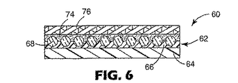
図6〜10に、図1〜5の実施形態のビーズボンド層または反射コーティングのない他の微粒子転写フィルム60を示す。図6に、キャリアバッキング64とその上のE−ビーム照射キャリアコーティング66との2つの構成要素を含む一時ビーズキャリア62を有する転写フィルム60を示す。ビーズ68がキャリアコーティング66(E−ビーム照射前)に含浸され、接着剤74が光学剥離ライナ76と共にビーズ68に適用されている。
FIGS. 6-10 illustrate another
図7においては、フィルム60の一部が除去されて、キャリアコーティング66の露出面90を含む除去領域86が形成されている。上述した通り、キャリアコーティングは熱硬化性であるため、光学ビーズの転写中、この露出面90は実質的に基材に転写されない。図8および9に、回転させて基材92上にボンドされ配置されたフィルム60を示す。図10に、一時ビーズキャリア62の除去(具体的には、キャリアコーティング66とキャリアバッキング64の除去)後に、接着剤74により定位置に保持されたビーズ68を含む基材92を示す。
In FIG. 7, a portion of the
本明細書で挙げた層の他に、様々な追加の層を本発明の開示内容の範囲内で任意で追加することができる。 In addition to the layers listed herein, various additional layers can optionally be added within the scope of the present disclosure.
B.一時ビーズキャリア
一時ビーズキャリアは、通常、紙やポリエステルのような任意の好適な材料であるキャリアバッキングと、元々熱可塑性であるが、光学ビーズまたはその他微粒子で含浸させた後は変性して熱硬化性となるキャリアコーティングとの2層からできている。このように、キャリアコーティングは、様々な具体例において、一般的に熱硬化性材料である、または熱硬化性材料から実質的になる、または主に熱硬化性材料である。透明なポリエステルフィルムが望ましいバッキングであり、次の3つの理由から好適である。第1に、紙より引裂き抵抗性があることである。これは、一時ビーズキャリアを除去したときの熱転写後に重要である。ポリエステルの引裂き抵抗性によって、一時ビーズキャリアを除去したときに均一かつ即時の動きが可能となり、時間、温度および圧力をはじめとする熱転写条件について広い処理ウィンドウが使えるようになる。第2に、ポリエステルキャリアの半透明性によって、基材へのフィルムのより正確な配置が可能となり、転写フィルムの基材への位置合せを容易に視認できるようになる。第3に、ポリエステルフィルムは、キャリアコーティングよりかなり高い軟化点を有しているため、一時ビーズキャリアが、キャリアコーティングを軟化するのに必要な温度で完全性を保持することができる。
B. Temporary bead carriers Temporary bead carriers are usually thermoplastic with any suitable material, such as paper and polyester, and are inherently thermoplastic, but are impregnated with optical beads or other particulates and then modified and thermoset. It consists of two layers with a carrier coating that makes it easier. Thus, the carrier coating, in various embodiments, is generally a thermoset material, consists essentially of or is primarily a thermoset material. A transparent polyester film is a desirable backing and is preferred for the following three reasons. First, it is more tear resistant than paper. This is important after thermal transfer when the temporary bead carrier is removed. The tear resistance of the polyester allows for uniform and immediate movement when the temporary bead carrier is removed, allowing a wider processing window for thermal transfer conditions including time, temperature and pressure. Secondly, the translucency of the polyester carrier allows for more accurate placement of the film on the substrate and allows easy alignment of the transfer film to the substrate. Third, because the polyester film has a much higher softening point than the carrier coating, the temporary bead carrier can maintain integrity at the temperature required to soften the carrier coating.
キャリアコーティング材料は、架橋して、熱硬化材を形成できる任意の好適な熱可塑性ポリマーとすることができ、任意の好適な厚さでコートすることができる。照射に際して架橋することが知られているポリマーとしては、ポリエチレンおよびその他ポリオレフィン、ポリアクリレートおよびその誘導体、ならびにポリスチレンが挙げられる。ある具体例において、キャリアコーティングは約1ミル(25μm)の厚さでポリエチレンコートされている。通常、キャリアコーティング材料は、加熱に際して最初は軟化しなければならないが、後に加熱の際にあまり軟化しないよう変性される、例えば、熱硬化性へと変換される。また、キャリアコーティングのキャリアバッキングへの適切な接着力もなければならない。これを行わないと、一時ビーズキャリアを除去するときにこれらの2枚の層は分離してしまい、転写フィルムの表面にキャリアコーティングが残ってしまう。 The carrier coating material can be any suitable thermoplastic polymer that can be crosslinked to form a thermoset, and can be coated at any suitable thickness. Polymers known to crosslink upon irradiation include polyethylene and other polyolefins, polyacrylates and derivatives thereof, and polystyrene. In one embodiment, the carrier coating is polyethylene coated with a thickness of about 1 mil (25 μm). Usually, the carrier coating material must first soften upon heating, but is later modified to be less softened upon heating, for example, converted to thermosetting. There must also be adequate adhesion of the carrier coating to the carrier backing. If this is not done, these two layers will separate when the temporary bead carrier is removed, leaving a carrier coating on the surface of the transfer film.
C.接着層
接着層は、一般に、再帰反射性転写フィルムが適用される基材と適合性があり、また用いている場合にはビーズボンドまたはビーズ/反射コーティングとも適合性のある任意の熱可塑性組成物とすることができる。好適な接着層としては、ポリエステル型熱可塑性ポリウレタン樹脂が挙げられる。接着剤は、様々なコーティングやラミネーション方法をはじめとする様々なやり方で適用することができる。例えば、一つの適用方法は、樹脂をシクロヘキサノンおよびメチルエチルケトンに溶解するものである。そしてロールコーティングを用いてコーティングを行って、1平方メートル当たり約30グラムの乾燥重量を有するコーティング厚さまたは約25ミクロンの厚さとする。接着層を適用する他の方法は、乾燥フィルムタイプのポリエステル型熱可塑性ポリウレタン樹脂をビーズボンド層に熱ラミネートすることである。一般的に、接着剤の融解温度は摂氏205度未満、より一般的には摂氏約90〜205度である。キャリアは、この接着温度より高い温度、通常は摂氏210度を超える温度で溶融する。
C. Adhesive Layer The adhesive layer is generally any thermoplastic composition that is compatible with the substrate to which the retroreflective transfer film is applied and, if used, compatible with bead bonds or bead / reflective coatings. It can be. A suitable adhesive layer includes a polyester-type thermoplastic polyurethane resin. The adhesive can be applied in various ways, including various coating and lamination methods. For example, one application method is to dissolve the resin in cyclohexanone and methyl ethyl ketone. The coating is then performed using roll coating to a coating thickness having a dry weight of about 30 grams per square meter or a thickness of about 25 microns. Another method of applying the adhesive layer is to heat laminate a dry film type polyester-type thermoplastic polyurethane resin to the bead bond layer. Generally, the melting temperature of the adhesive is less than 205 degrees Celsius, more typically about 90-205 degrees Celsius. The carrier melts at a temperature above this bonding temperature, usually above 210 degrees Celsius.
D.ビーズ
様々な種類のビーズを本発明で用いてよく、光学および非光学ガラスビーズおよび球、非球面または球でないその他小微粒子材料が挙げられる。平均サイズは、一般的に、40ミクロンを超え、120ミクロン未満であるが、この範囲外のサイズを用いることもできる。再帰反射性転写フィルムに用いるガラスビーズの屈折率は約1.9、直径の中心サイズは60ミクロンである。目的の用途に応じてその他の材料、サイズおよび屈折率を用いることもできる。これらの変数は、通常、熱転写に大幅に影響することはない。
D. Beads Various types of beads may be used in the present invention, including optical and non-optical glass beads and spheres, aspherical or other small particulate materials that are not spheres. The average size is generally greater than 40 microns and less than 120 microns, but sizes outside this range can also be used. The glass beads used for the retroreflective transfer film have a refractive index of about 1.9 and a central diameter size of 60 microns. Other materials, sizes and refractive indices can be used depending on the intended application. These variables usually do not significantly affect thermal transfer.
E.追加の層
多くの具体例において、転写フィルムはまた、ビーズに適用された反射コーティングと、ビーズを互いに、そして接着剤に固定するビーズボンド層のような追加の層および材料も含んでいる。ビーズに適用された反射コーティングは、大幅に反射性を改善することができる。好適な反射コーティングとしては、スパッタされたアルミニウムその他金属のような金属コーティングが挙げられる。フレーキ(真珠光沢)反射層または透明鏡(誘電体スタック)も組み込むことができる。ビーズボンド層および反射コーティングは、ビーズを互いに固定し、接着剤に基材も提供する。ビーズボンド層は、ビーズ(金属コートビーズを含む)を固定し、接着剤にボンドして、高温で劣化しないようなものを選択しなければならない。ビーズボンド層は、例えば、フェノール樹脂およびニトリルブタジエンゴムとすることができる。
E. Additional Layers In many embodiments, the transfer film also includes additional layers and materials such as a reflective coating applied to the beads and a bead bond layer that secures the beads to each other and to the adhesive. A reflective coating applied to the beads can significantly improve reflectivity. Suitable reflective coatings include metal coatings such as sputtered aluminum and other metals. A flake (pearlescent) reflective layer or a transparent mirror (dielectric stack) can also be incorporated. The bead bond layer and the reflective coating secure the beads to each other and also provide a substrate for the adhesive. The bead bond layer must be selected such that it fixes the beads (including metal coated beads), bonds to the adhesive and does not degrade at high temperatures. The bead bond layer can be, for example, phenol resin and nitrile butadiene rubber.
米国特許第3,172,942号明細書(ベルグ(Berg))に教示されるようなものをはじめとする、業界に公知の様々なその他の材料および方法を本発明で用いてよい。 Various other materials and methods known in the industry may be used with the present invention, including those taught in US Pat. No. 3,172,942 (Berg).
F.微粒子転写フィルムの作成方法
本明細書にはまた、微粒子転写フィルムの作成方法も開示されている。様々な方法、特に、ビーズを熱可塑性キャリアコーティングに結合して、キャリアコーティングを熱硬化性または実質的に熱硬化性の材料に変換する方法を用いることができる。熱硬化性キャリアコーティングは、キャリアコーティングを基材へ転写させることなく、高温でのビーズの基材への適用を促進する。
F. Method for Producing Fine Particle Transfer Film The present specification also discloses a method for producing a fine particle transfer film. Various methods can be used, particularly methods in which the beads are bonded to a thermoplastic carrier coating to convert the carrier coating into a thermoset or substantially thermoset material. A thermoset carrier coating facilitates application of the beads to the substrate at high temperatures without transferring the carrier coating to the substrate.
一具体例において、キャリアバッキング材料(ポリエステルや紙)は、ポリエチレンの層のような熱可塑性層でコートされて、一時ビーズキャリアを形成する。従来のコーティング方法を用いて、バッキング材料と熱可塑性コーティング層とを有するこの一時ビーズキャリアを形成することができる。透明ガラスビーズを一時ビーズキャリアにコートして、キャリアコーティングに埋め込む。このコーティングおよび含浸プロセスの一つの目標は、密に充填されたビーズの単層を得ることである。 In one embodiment, the carrier backing material (polyester or paper) is coated with a thermoplastic layer, such as a layer of polyethylene, to form a temporary bead carrier. This temporary bead carrier having a backing material and a thermoplastic coating layer can be formed using conventional coating methods. Transparent glass beads are coated on a temporary bead carrier and embedded in the carrier coating. One goal of this coating and impregnation process is to obtain a monolayer of closely packed beads.
ビーズをコーティングするプロセスは、キャリアバッキングを熱缶と接触させながら熱缶に通して、一時ビーズキャリアの加熱により行うことができる。熱缶は、熱可塑性キャリアコーティングが粘着性となるのに十分な温度まで加熱する。ある具体例においては、一時ビーズキャリアの温度は75℃まで上げる。透明ガラスビーズを粘着性のキャリアコーティングに適用する。キャリアベースのキャリアコーティングの粘着性によって、ガラスビーズの単層がキャリアフィルムにより持ち上げられる。次に、ガラスビーズ単層を備えた一時ビーズキャリアを加熱する。一時ビーズキャリアおよびガラスビーズは、通常、キャリアコーティングを軟化してビーズをそこに沈める温度まで加熱される。ビーズをキャリアコーティングにどの位深く沈めるかを制御するのに用いることのできる時間および温度は可変である。ビーズを高温でキャリアフィルムに維持するのが長ければ長いほど、キャリアコーティングにより深く沈む。同様に、キャリアコーティングの軟化を増大させる高温の結果、キャリアコーティングへより深くビーズは沈む。 The process of coating the beads can be performed by heating the temporary bead carrier by passing the carrier backing through the heat can while in contact with the heat can. The heat can is heated to a temperature sufficient for the thermoplastic carrier coating to become tacky. In certain embodiments, the temperature of the temporary bead carrier is raised to 75 ° C. Transparent glass beads are applied to the sticky carrier coating. The adhesion of the carrier-based carrier coating causes the monolayer of glass beads to be lifted by the carrier film. Next, the temporary bead carrier provided with the glass bead monolayer is heated. Temporary bead carriers and glass beads are typically heated to a temperature at which the carrier coating is softened and the beads are submerged therein. The time and temperature that can be used to control how deep the beads are submerged in the carrier coating are variable. The longer the beads are kept on the carrier film at higher temperatures, the deeper they sink into the carrier coating. Similarly, the high temperature that increases the softening of the carrier coating results in the beads sinking deeper into the carrier coating.
最終製品の輝度半値角は、キャリアコーティングに沈むビーズの量によって制御することができる。沈めるのを多くすると、輝度半値角は増大し、沈めるのを少なくすると減少する。一時ビーズキャリアを除去しにくくなる恐れがあるため、ビーズを沈めすぎないよう注意を要する。適正なレベルの沈み(ビーズ直径の約半分)を行った後、キャリアコーティングを固化し、ビーズが動かないようにするために、ガラスビーズと共に一時ビーズキャリアを室温まで冷やす。 The luminance half-value angle of the final product can be controlled by the amount of beads that sink into the carrier coating. Increasing sinking increases the luminance half-value angle, and decreasing sinking decreases it. Care must be taken not to submerge the beads, as it may be difficult to remove the temporary bead carrier. After the proper level of sinking (about half the bead diameter), the temporary bead carrier is cooled to room temperature with the glass beads to solidify the carrier coating and keep the beads from moving.
半球反射コーティングを一時ビーズキャリアのビーズ側に任意で適用する。これは、光を反射する任意の好適な材料、例えば、銀、アルミニウムまたは真珠光沢顔料により行うことができる。例えば、アルミニウムは蒸着により適用することができる。アルミニウムは、ビーズの露出面およびビーズ間の領域にあるキャリアコーティングをカバーする。次に、フィルム(ウェブであることが多い)を放射線に露光して、熱可塑性キャリアコーティングを架橋し、熱硬化性材料に変換する。高エネルギー電子を用いる電子ビーム放射線がこの工程を実施する一つのやり方である。電子ビームは、ビーズの一時ビーズキャリアへの接着力を増大して、ビーズおよび接着剤を一時ビーズキャリアから剥がすことなく、折り畳まれたり引裂かれることにより欠陥を生じることなく、キスカットを行う。他の架橋の方法としては、ガンマまたはx線、過酸化物架橋またはシラン架橋のような高エネルギー放射線が挙げられる。 A hemispherical reflective coating is optionally applied to the bead side of the temporary bead carrier. This can be done with any suitable material that reflects light, such as silver, aluminum or pearlescent pigments. For example, aluminum can be applied by vapor deposition. The aluminum covers the carrier coating on the exposed surface of the beads and the area between the beads. The film (often a web) is then exposed to radiation to crosslink the thermoplastic carrier coating and convert it to a thermoset material. Electron beam radiation using high energy electrons is one way of performing this process. The electron beam increases the adhesion of the beads to the temporary bead carrier and kiss-cuts without peeling the beads and adhesive from the temporary bead carrier and without causing defects by folding or tearing. Other crosslinking methods include high energy radiation such as gamma or x-ray, peroxide crosslinking or silane crosslinking.
ある具体例において、架橋工程は、反射コーティングを適用した後に行う。ビーズを適用する前にE−ビーム照射を行う場合には、熱可塑性ではなく熱硬化性となるためキャリアコーティングはビーズを持ち上げ沈ませない。ビーズを一時ビーズキャリアに適用した後であるが、反射コーティングを適用する前にE−ビーム照射を行う場合には、最終製品の熱ラミネーション後、図12に示すように、一時ビーズキャリアを除去するのに必要な剥離力が非常に増大する。大量のE−ビーム照射は、ビーズボンド層または接着層を適用した後は行わない方が好ましい。E−ビームプロセスは、これらの層を劣化する可能性があり、キャリアコーティングを透過して所望の効果を必ずしも与えないためである。 In certain embodiments, the crosslinking step is performed after applying the reflective coating. If E-beam irradiation is performed before the beads are applied, the carrier coating does not lift and sink the beads because it is thermoset rather than thermoplastic. If E-beam irradiation is performed after the beads are applied to the temporary bead carrier but before the reflective coating is applied, the temporary bead carrier is removed as shown in FIG. 12 after thermal lamination of the final product. The peel force required for this is greatly increased. It is preferable not to perform a large amount of E-beam irradiation after applying the bead bond layer or the adhesive layer. This is because the E-beam process can degrade these layers and does not necessarily provide the desired effect through the carrier coating.
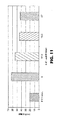
線量と呼ばれ、ラドまたはメガラド(Mrad)で測定されるE−ビーム放射線の量またはレベルは、露光時間、電圧および電流の変数により制御される。図11に、E−ビーム処理によって、一時ビーズキャリアを転写フィルムから分離するのに必要な剥離力がE−ビーム処理をしない場合と比べて増大するのが示されている。線量がさらに増大すると、一時キャリアを転写フィルムから除去する力が減少する。 The amount or level of E-beam radiation, called dose and measured in rads or megarads (Mrad), is controlled by exposure time, voltage and current variables. FIG. 11 shows that the E-beam treatment increases the peel force required to separate the temporary bead carrier from the transfer film compared to the case without E-beam treatment. As the dose increases further, the force to remove the temporary carrier from the transfer film decreases.
図13に、線量と、一時ビーズキャリアを布帛基材から除去するのに必要な剥離力との関係を示す。これは、一時ビーズキャリアが無傷のままキスカットおよびウィードされた転写フィルムが基材に熱ラミネートされるときに生じる状況である。一時ビーズキャリアの露出領域を熱ラミネーション工程中に基材にボンドすることができる。一般的に、キャリアコーティング(架橋されていなかった場合)の軟化点は、接着層の活性温度より低い。しかしながら、層が熱硬化性であれば、大幅に軟化せず、基材に接合したり、キスカットおよびウィードされた転写フィルムの露出領域において基材に残渣が残らない。 FIG. 13 shows the relationship between the dose and the peel force required to remove the temporary bead carrier from the fabric substrate. This is the situation that occurs when the kiss cut and weed transfer film is heat laminated to the substrate while the temporary bead carrier is intact. The exposed area of the temporary bead carrier can be bonded to the substrate during the thermal lamination process. In general, the softening point of the carrier coating (if not crosslinked) is below the activation temperature of the adhesive layer. However, if the layer is thermosetting, it will not soften significantly, leaving no residue on the substrate in the exposed areas of the transfer film that have been joined or kiss cut and weeded.
次に、ビーズボンド層を任意で適用する。ビーズボンド層の機能は、コートされたビーズ(またはその他微粒子)を使用中適所に保持することである。洗浄、ドライクリーニング、摩耗等に耐えられるよう、通常、適正な接着力が得られる必要がある。ビーズボンド層は、ニトリルブタジエンゴム、フェノール樹脂、ステアリン酸および可塑剤またはその他材料を含む混合物から構成することができる。これらの成分をコートするには、メチルイソブチルケトンとトルエンのような溶剤を用いて溶液を作成する。 Next, a bead bond layer is optionally applied. The function of the bead bond layer is to hold the coated beads (or other particulates) in place during use. In order to withstand washing, dry cleaning, abrasion, etc., it is usually necessary to obtain an appropriate adhesive force. The bead bond layer can be composed of a mixture comprising nitrile butadiene rubber, phenolic resin, stearic acid and plasticizer or other materials. To coat these components, a solution is made using a solvent such as methyl isobutyl ketone and toluene.
次に、接着層を様々な従来の方法を用いてビーズボンド層を覆うように適用する。接着剤は、再帰反射性転写フィルムが適用される基材と適合性のある任意の熱可塑材とする。好適な接着層としては、ポリエステル型熱可塑性ポリウレタン樹脂が挙げられる。 The adhesive layer is then applied over the bead bond layer using a variety of conventional methods. The adhesive is any thermoplastic that is compatible with the substrate to which the retroreflective transfer film is applied. A suitable adhesive layer includes a polyester-type thermoplastic polyurethane resin.
一時接着剥離ライナも追加することができる。通常、剥離ライナと接着層間の接着力のレベルは、一時ビーズキャリアコーティングと再帰反射性転写フィルムのビーズ表面間の接着力のレベルより小さくなければならない。そうしないと、剥離ライナを除去しようとしたときに、ビーズ層が一時ビーズキャリアから分離されてしまう。剥離ライナの接着剤への接着力を制限するために、ライナはポリエチレンのような低表面エネルギー材料としなければならない。 A temporary adhesive release liner can also be added. Typically, the level of adhesion between the release liner and the adhesive layer should be less than the level of adhesion between the bead surface of the temporary bead carrier coating and the retroreflective transfer film. Otherwise, the bead layer will be separated from the temporary bead carrier when attempting to remove the release liner. In order to limit the adhesion of the release liner to the adhesive, the liner must be a low surface energy material such as polyethylene.
G.実施例
さらなる実施形態を以下の実施例により例証する。実施例に挙げた特定の材料およびその量、ならびにその他条件および詳細は、限定するものとは考えられず、例証の目的で与えられているものとする。特に断りのない限り、部は全て重量基準である。
G. Examples Further embodiments are illustrated by the following examples. The specific materials and amounts listed in the examples, as well as other conditions and details, are not considered to be limiting and are given for illustrative purposes. Unless otherwise noted, all parts are by weight.
試験を行って、転写フィルムをプロッタで切断した際の次の2つの関連した特性を測定した。(1)ラミネーションの前に一時ビーズキャリアを転写フィルムの残りの部分から除去するのに必要な剥離力、(2)直接ラミネーション後に一時ビーズキャリアを基材材料から除去するのに必要な剥離力。第1の特性は、プロッタ切断後にウィード材料を効率的に除去するのに重要である。適用プロセスにおいて、剥離力がこの時点で高すぎる場合には、廃棄材料を除去するのが困難であるためウィーディングが非常に遅くなり、不十分となる。剥離力が適用プロセスのこの時点で低すぎる場合には、プロッタ切断中、一時ビーズキャリアからビーズの早期の層剥離が生じる恐れがある。基材にラミネートされた一時ビーズキャリアを除去する第2の特性は、キャリアコーティングの基材への転写を減じる、または排除するのに重要である。かかる転写によって、転写された図形やインディシアの周囲領域に残渣が残り、化粧用としては受け入れられない。さらに、かかる転写によって、一時ビーズキャリアを基材から除去するのが難しくなる。 Tests were conducted to measure the following two related properties when the transfer film was cut with a plotter. (1) Peeling force required to remove the temporary bead carrier from the rest of the transfer film before lamination, (2) Peeling force required to remove the temporary bead carrier from the substrate material after direct lamination. The first property is important for efficiently removing the weed material after cutting the plotter. In the application process, if the peel force is too high at this point, weeding becomes very slow and inadequate because it is difficult to remove the waste material. If the peel force is too low at this point in the application process, premature delamination of the beads from the temporary bead carrier may occur during plotter cutting. The second property of removing the temporary bead carrier laminated to the substrate is important to reduce or eliminate transfer of the carrier coating to the substrate. Such transfer leaves a residue in the area around the transferred graphic or indicia and is not acceptable for cosmetic purposes. Furthermore, such transfer makes it difficult to remove the temporary bead carrier from the substrate.
インストロン社(Instron Corporation)(マサチューセッツ州カントン(Canton,Massachusetts))より入手可能な、2,000グラムのロードセル、ピールバック低摩擦ジグを含むローラと、幅2.5cmの両面テープのロールを備えたインストロン(Instron)5565力測定システムにより材料を試験した。アルミニウムと試験試料に適切に接合するものであれば他の両面テープも用いることができる。さらに、アルミニウムパネルとHIX社(HIX Corporation)(カンザス州ピッツバーグ(Pittsburgh,Kansas))より入手可能なHIXラミネーションプレス型番N−800を用いた。 Includes a roller with a 2,000 gram load cell, peelback low friction jig available from Instron Corporation (Canton, Massachusetts) and a roll of double-sided tape 2.5 cm wide The material was tested with an Instron 5565 force measurement system. Other double-sided tapes can be used as long as they are appropriately bonded to aluminum and the test sample. Furthermore, an aluminum panel and HIX lamination press model number N-800 available from HIX Corporation (Pittsburgh, Kansas) were used.
以下の試験手順を行って、第1の特性、転写フィルムを基材にラミネーションする前の、転写フィルムの残りの部分から一時ビーズキャリアを除去するのに必要な剥離力を測定した。剥離力は製造後最初の数時間は大幅に変化して、その後安定するため、シートを作成した後少なくとも12時間、剥離力を測定した。インストロン(Instron)システムを2,000グラムのロードセルを用いて較正した。剥離ライナをフィルムから除去し、2.5cm×18cmの試料をシートから切断した。幅2.5cmの両面テープ片を、長手方向に、5cm×23cmのアルミニウムパネルの中心に適用することによりアルミニウムパネルを作成した。テープを強圧力でゴムロールに巻き付けた。ライナを両面テープから除去し、2.5cm×18cmのフィルム試料を両面テープに配置して、一時ビーズキャリアと対面させた。試料を適用して、両面テープの左右を完全にカバーした。試料も強圧力でゴムロールに巻き付けた。約5cmの一時ビーズキャリアを試料から剥がして、試料が一時ビーズキャリアと転写フィルムの残りの部分との間で確実に分離されるようにした。アルミニウムパネル/試料を、ピールバック低摩擦ジグを含むローラに配置して、試料を上げた。部分的に剥がれた一時ビーズキャリアをインストロン(Instron)の上部ジョーに配置した。1分当たり30cmのクロスヘッド速度を用いて、一時ビーズキャリアを試料全体から剥がした。記録の3つの最高ピークを求めた。試験の最初と最後の0.6cmは無視した。3つのピークの平均を計算し、この平均値を記録した。図11に示すデータについては、各データ点は試験した3つの試料の平均であり、図12に示すデータについては、各データ点は試験した2つの試料の平均である。 The following test procedure was performed to measure the first property, the peel force required to remove the temporary bead carrier from the remaining portion of the transfer film before lamination of the transfer film to the substrate. The peel force changed significantly during the first few hours after production and then stabilized, so the peel force was measured for at least 12 hours after making the sheet. The Instron system was calibrated using a 2,000 gram load cell. The release liner was removed from the film and a 2.5 cm x 18 cm sample was cut from the sheet. An aluminum panel was made by applying a 2.5 cm wide double-sided tape piece in the longitudinal direction to the center of an aluminum panel of 5 cm × 23 cm. The tape was wound around a rubber roll with high pressure. The liner was removed from the double-sided tape, and a 2.5 cm x 18 cm film sample was placed on the double-sided tape to face the temporary bead carrier. The sample was applied to completely cover the left and right sides of the double-sided tape. The sample was also wound around a rubber roll with high pressure. Approximately 5 cm of the temporary bead carrier was peeled from the sample to ensure that the sample was separated between the temporary bead carrier and the rest of the transfer film. The aluminum panel / sample was placed on a roller containing a peelback low friction jig to raise the sample. The partially peeled temporary bead carrier was placed in the upper jaw of the Instron. The temporary bead carrier was peeled from the entire sample using a crosshead speed of 30 cm per minute. The three highest peaks in the record were determined. The first and last 0.6 cm of the test was ignored. The average of the three peaks was calculated and this average value was recorded. For the data shown in FIG. 11, each data point is the average of three samples tested, and for the data shown in FIG. 12, each data point is the average of two samples tested.
第2の特性、基材材料にラミネートされた一時ビーズキャリアを除去するのに必要な剥離力も測定した。この剥離力を基材へのラミネーション後即時にあるいは直後に測定した。インストロン(Instron)5565システムを2,000グラムのロードセルを用いて較正した。剥離ライナを微粒子転写フィルムから除去して、試料を2.5cm×18cmの片に切断した。一時ビーズキャリアを転写フィルムの残り部分から除去して分離した。一時ビーズキャリアの2.5cm×18cmの試料を、試料布帛基材として選択したエクセラレート(Excellarate)布帛にHIXプレスを用いて、キャリアコーティング側を基材に向けてラミネートした。エクセラレート(Excellerate)布帛は、重量が105g/m2、白色、縦糸数が約115、横糸数が約76の65%ポリエステルと35%綿ブレンドであった。この材料はスプリングスインダストリーズ(Springs Industries)(サウスカロライナ州ロックヒル(Rock Hill,South Carolina))より購入できる。ラミネーションに用いる条件は、流路圧力2.1kg/cm2、時間20秒、温度は試料によって104℃〜210℃まで変えた。ラミネートされた2.5cm×18cmの一時ビーズキャリアから布帛を鋏またはその他適切な切断器具を用いてトリミングした。幅2.5cmの両面テープ片を、長手方向に、5cm×23cmのアルミニウムパネルの中心に適用することによりアルミニウムパネルを作成した。テープを強圧力でゴムロールに巻き付けた。 The second property, the peel force required to remove the temporary bead carrier laminated to the substrate material, was also measured. This peel force was measured immediately or immediately after lamination to the substrate. The Instron 5565 system was calibrated using a 2,000 gram load cell. The release liner was removed from the particulate transfer film and the sample was cut into 2.5 cm × 18 cm pieces. The temporary bead carrier was removed from the rest of the transfer film and separated. A 2.5 cm x 18 cm sample of a temporary bead carrier was laminated to an Excellarate fabric selected as the sample fabric substrate using a HIX press with the carrier coating side facing the substrate. The Excellerate fabric was a 65% polyester and 35% cotton blend with a weight of 105 g / m 2 , white, about 115 warp yarns and about 76 weft yarns. This material can be purchased from Springs Industries (Rock Hill, South Carolina). The conditions used for lamination were a channel pressure of 2.1 kg / cm 2 , a time of 20 seconds, and the temperature varied from 104 ° C. to 210 ° C. depending on the sample. Fabrics were trimmed from the laminated 2.5 cm x 18 cm temporary bead carrier using scissors or other suitable cutting instrument. An aluminum panel was made by applying a 2.5 cm wide double-sided tape piece in the longitudinal direction to the center of an aluminum panel of 5 cm × 23 cm. The tape was wound around a rubber roll with high pressure.
剥離ライナを両面テープから除去し、2.5cm×18cmの試料を両面テープに適用して、一時ビーズキャリア側を上にした。試料を適用して、両面テープの左右を完全にカバーした。試料を強圧力でゴムロールに巻き付けた。約5cmの一時ビーズキャリアを試料から剥がして、試料が一時ビーズキャリアと布帛との間で確実に分離されるようにした。アルミニウムパネル/試料を、ピールバック低摩擦ジグを含むローラに配置して、試料を上げた。1分当たり30cmのクロスヘッド速度を用いて、一時ビーズキャリアを試料全体から剥がした。記録の3つの最高ピークを求めた。試験の最初と最後の0.6cmは無視した。3つのピークの平均を計算し、この平均値を記録した。図13の各データ点は試験した3つの試料の平均である。剥離力が強くなると、両面テープを、より攻撃的で、一時ビーズキャリアを剥がす間布帛を定位置に保持する他の好適な両面テープに変える必要がある。 The release liner was removed from the double-sided tape and a 2.5 cm x 18 cm sample was applied to the double-sided tape with the temporary bead carrier side up. The sample was applied to completely cover the left and right sides of the double-sided tape. The sample was wound around a rubber roll with high pressure. Approximately 5 cm of the temporary bead carrier was peeled from the sample to ensure that the sample was separated between the temporary bead carrier and the fabric. The aluminum panel / sample was placed on a roller containing a peelback low friction jig to raise the sample. The temporary bead carrier was peeled from the entire sample using a crosshead speed of 30 cm per minute. The three highest peaks in the record were determined. The first and last 0.6 cm of the test was ignored. The average of the three peaks was calculated and this average value was recorded. Each data point in FIG. 13 is an average of three samples tested. As the peel force increases, the double-sided tape needs to be changed to another suitable double-sided tape that is more aggressive and holds the fabric in place while peeling the temporary bead carrier.
実施例1
本実施例は、有利な特性を与えるのに必要なおおよそのE−ビーム線量を求めるために行った。
Example 1
This example was done to determine the approximate E-beam dose necessary to give the advantageous properties.
一時ビーズキャリアは、ポリエチレン(25μm)でコートされたポリエチレンテレフタレート(PET)フィルム(95μm)から構成されていた。平均直径60μm、屈折率1.9のビーズを一時ビーズキャリアに適用し、続いて、厚さ約90nmのアルミニウム層を適用した。フィルムにE−ビーム照射し、ビームをまず、PETでなくビーズに通過させた。ビーズボンド材料(ニトリルブタジエンゴム、フェノール樹脂、ステアリン酸および可塑剤)を、アルミナイズドビーズと一時キャリアに約34グラム/1平方メートルの重量でコートした。ビーズボンドコートフィルムを、約60℃で始め、約166℃まで6分間にわたって上げながら乾燥および硬化させた。 The temporary bead carrier consisted of a polyethylene terephthalate (PET) film (95 μm) coated with polyethylene (25 μm). Beads with an average diameter of 60 μm and a refractive index of 1.9 were applied to a temporary bead carrier followed by an aluminum layer of about 90 nm thickness. The film was irradiated with E-beam and the beam was first passed through the beads, not PET. Bead bond materials (nitrile butadiene rubber, phenolic resin, stearic acid and plasticizer) were coated on aluminized beads and temporary carrier at a weight of about 34 grams per square meter. The bead bond coat film was dried and cured starting at about 60 ° C. and raised to about 166 ° C. over 6 minutes.
接着剤は、ポリエステル型熱可塑性ポリウレタン樹脂であり、1平方メートル当たり約31グラムの重量でコートし、約71℃で始め、約118℃まで6.5分間にわたって上げながら乾燥した。接着剤を、シクロヘキサノンおよびメチルエチルケトンに樹脂を溶融することにより適用した。ロールコーターを用いてコーティングを行って、1平方メートル当たり約31グラムの乾燥重量を有するコーティング厚さまたは約25ミクロンの厚さを得た。 The adhesive was a polyester type thermoplastic polyurethane resin, coated at a weight of about 31 grams per square meter, dried at about 71 ° C. and raised to about 118 ° C. over 6.5 minutes. The adhesive was applied by melting the resin in cyclohexanone and methyl ethyl ketone. Coating was performed using a roll coater to obtain a coating thickness having a dry weight of about 31 grams per square meter or a thickness of about 25 microns.
ライン速度27m/分で線量計を用いてE−ビーム線量を測定した。他のライン速度での線量をその値から計算した。E−ビーム条件は175kV、140mAであり、ライン速度を変えて、フィルムを放射線に露光した時間の量および線量を変更した。図11に、E−ビームの線量レベルによって、一時ビーズキャリアからビーズを分離するのにどのくらい剥離力が必要であるかを示す。ライン速度が減少すると、線量が増大した。16.2Mradで許容される結果が得られたが、27Mradでの結果が優れていた。27Mradでは、線速度は約9.1m/分であった。約40Mradの線量に対応する6.1m/分のライン速度では、適用された線量だとPETキャリアバッキングが破損した。これらの結果によれば、E−ビーム照射線量が、キャリアバッキングの引張り強度に結びついていて、放射線への露光によりいかに変化するかが分かる。この結果に基づいて、例証の本実施例の条件下では、好ましい線量は約27メガラドであると結論される。E−ビーム照射試料を、E−ビーム照射しなかった試料と比べると、プロッタ切断により問題がなかったことも分かり、キスカットプロセス中、より高い剥離力が有効であることが確認された。 E-beam dose was measured using a dosimeter at a line speed of 27 m / min. Dose at other line speeds was calculated from that value. The E-beam condition was 175 kV, 140 mA, and the line speed was varied to change the amount of time and dose that the film was exposed to radiation. FIG. 11 shows how much peel force is required to separate the beads from the temporary bead carrier, depending on the dose level of the E-beam. As the line speed decreased, the dose increased. Results acceptable at 16.2 Mrad were obtained, but results at 27 Mrad were excellent. At 27 Mrad, the linear velocity was about 9.1 m / min. At a line speed of 6.1 m / min, corresponding to a dose of about 40 Mrad, the PET carrier backing was damaged at the applied dose. These results show how the E-beam irradiation dose is linked to the tensile strength of the carrier backing and how it changes with exposure to radiation. Based on this result, it is concluded that the preferred dose is about 27 megarads under the conditions of this illustrative example. Comparing the E-beam irradiated sample with the sample not subjected to E-beam irradiation, it was also found that there was no problem due to the plotter cutting, and it was confirmed that a higher peeling force was effective during the kiss cutting process.
実施例2
本実施例は、E−ビーム照射をアルミニウム蒸気コートをビーズに適用する前または後に行うべきであるかを判断するために行った。図12に、再帰反射コーティングをビーズに適用した後と、ガラスビーズを一時ビーズキャリアコートした後だが再帰反射コーティングの前のE−ビーム照射の差を示す。実施例1と同じ方法および材料を用いた。この例のE−ビーム照射は18メガラド(12m/分、175kVおよび108mA)の線量で行った。この結果の結果によれば、この試験条件下では、アルミニウム蒸気コートをビーズに適用した後にE−ビーム照射を行うと有利であることが分かる。
Example 2
This example was performed to determine whether E-beam irradiation should be performed before or after applying the aluminum vapor coat to the beads. FIG. 12 shows the difference in E-beam irradiation after the retroreflective coating is applied to the beads and after the glass beads are temporarily bead carrier coated but before the retroreflective coating. The same methods and materials as in Example 1 were used. The E-beam irradiation in this example was performed at a dose of 18 megarads (12 m / min, 175 kV and 108 mA). The results of this result show that under this test condition, it is advantageous to perform E-beam irradiation after the aluminum vapor coat is applied to the beads.
118g/cm未満の剥離力であれば顧客に許容されることが多いが、118g/cmを超える剥離力だと、問題が発生し始め、197g/cmを超えると許容されなくなることが多い。E−ビーム照射をしていない試料に比べて、E−ビーム工程を再帰反射コーティング後に行うと剥離力が僅かに増大することが本発明の利点の一つである。転写フィルムのキスカット性を改善すると、持ち上げ、折り畳みおよび引裂きを排除するのに役立つ。放射線工程を、ビーズコーティング操作の後、蒸気コーティング操作の前に実施するときの非常に高レベルの剥離力は、この工程でE−ビーム照射を実施するのはあまり望ましくないことを示している。 If the peel force is less than 118 g / cm, it is often acceptable for customers. However, if the peel force exceeds 118 g / cm, problems start to occur, and if it exceeds 197 g / cm, it is often not acceptable. One advantage of the present invention is that the peel force slightly increases when the E-beam process is performed after retroreflective coating as compared to a sample that has not been irradiated with E-beam. Improving the kiss cut properties of the transfer film helps eliminate lifting, folding and tearing. The very high level of peel force when the radiation process is performed after the bead coating operation and before the vapor coating operation indicates that it is less desirable to perform E-beam irradiation in this process.
実施例3
本実施例は、図13に示すように、基材への露出したキャリアコーティングラミネーションの接着レベルに与えるE−ビーム照射の影響を示すものである。実施例1と同じ方法および材料を用いた。試料を65%ポリエステル、35%綿の布帛に熱プレスを用いてラミネートした。熱プレスの圧力を2.1kg/cm2、ラミネーション時間を20秒に設定した。温度を変えた。図示するように、高線量レベルのE−ビーム放射線は、基材からラミネートされた露出一時ビーズキャリアを除去するのに必要な力を減じる。剥離力は、E−ビーム照射した材料はE−ビーム照射していない材料に比べて凡そ1〜2小さい。この剥離力はまた、様々な好適なラミネーション温度について非常に一致しており、本発明により得られる利点である。
Example 3
This example shows the effect of E-beam irradiation on the adhesion level of the exposed carrier coating lamination to the substrate, as shown in FIG. The same methods and materials as in Example 1 were used. The sample was laminated to a 65% polyester, 35% cotton fabric using a hot press. The pressure of the hot press was set to 2.1 kg / cm 2 and the lamination time was set to 20 seconds. Changed temperature. As shown, high dose levels of E-beam radiation reduce the force required to remove the laminated exposed temporary bead carrier from the substrate. The peel force is approximately 1-2 smaller for the material irradiated with E-beam than for the material not irradiated with E-beam. This peel force is also very consistent for various suitable lamination temperatures and is an advantage obtained by the present invention.
本発明は、その技術思想および本質的な特性から逸脱することなく、他の特定の形態で実施してよい。記載した実施形態は全ての点において、例証のためであり、限定するものとは考えられない。従って、本発明の範囲は、前述の説明よりも、添付の特許請求の範囲により示される。 The present invention may be embodied in other specific forms without departing from its technical spirit and essential characteristics. The described embodiments are in all respects illustrative and are not to be considered limiting. The scope of the invention is, therefore, indicated by the appended claims rather than by the foregoing description.
Claims (22)
前記一時キャリアバッキングに配置された一時キャリア組成物と、
前記一時キャリア組成物に部分的に埋め込まれた微粒子と
を含み、前記一時キャリア組成物が熱硬化性組成物を含む、一時微粒子キャリアフィルム。 Temporary carrier backing,
A temporary carrier composition disposed in the temporary carrier backing;
A temporary particulate carrier film comprising fine particles partially embedded in the temporary carrier composition, wherein the temporary carrier composition comprises a thermosetting composition.
前記一時キャリアバッキングに配置された一時キャリア組成物と、
前記一時キャリア組成物に部分的に埋め込まれた微粒子と
を含み、前記一時キャリア組成物が架橋熱可塑性ポリマーを含む、一時微粒子キャリアフィルム。 Temporary carrier backing,
A temporary carrier composition disposed in the temporary carrier backing;
A temporary particulate carrier film comprising fine particles partially embedded in the temporary carrier composition, wherein the temporary carrier composition comprises a crosslinked thermoplastic polymer.
前記光学ビーズを基材に永続的に接合するよう構成された、軟化温度が90〜205℃の接着層と、
前記ビーズを保持する一時キャリア層であって、軟化温度が210℃を超える架橋ポリオレフィンを含む一時キャリア層と
を含み、前記ビーズを前記基材に永続的に接合する際に前記一時キャリア層が前記ビーズを放出するよう構成されている、ビーズを基材に転写するよう構成された、微粒子転写フィルム With optical beads,
An adhesive layer having a softening temperature of 90-205 ° C. configured to permanently bond the optical beads to a substrate;
A temporary carrier layer for holding the beads, the temporary carrier layer comprising a crosslinked polyolefin having a softening temperature exceeding 210 ° C., and the temporary carrier layer when the beads are permanently bonded to the substrate. Particulate transfer film configured to transfer beads to a substrate configured to release beads
前記バッキングフィルムに熱可塑性組成物を適用する工程と、
前記熱可塑性層に微粒子材料を含浸する工程と、
前記熱可塑性組成物を架橋して熱硬化性組成物を形成する工程と
を含む、微粒子転写フィルムの製造方法。 Providing a backing film;
Applying a thermoplastic composition to the backing film;
Impregnating the thermoplastic layer with a particulate material;
And a step of forming a thermosetting composition by crosslinking the thermoplastic composition.
The method of claim 21, wherein the adhesive comprises a thermoplastic composition.
Applications Claiming Priority (2)
| Application Number | Priority Date | Filing Date | Title |
|---|---|---|---|
| US10/210,924 US20040023019A1 (en) | 2002-08-02 | 2002-08-02 | Particulate transfer film with improved bead carrier |
| PCT/US2003/018321 WO2004013665A1 (en) | 2002-08-02 | 2003-06-10 | Particulate transfer film with improved bead carrier |
Publications (2)
| Publication Number | Publication Date |
|---|---|
| JP2005534979A true JP2005534979A (en) | 2005-11-17 |
| JP2005534979A5 JP2005534979A5 (en) | 2006-08-03 |
Family
ID=31187466
Family Applications (1)
| Application Number | Title | Priority Date | Filing Date |
|---|---|---|---|
| JP2004525995A Withdrawn JP2005534979A (en) | 2002-08-02 | 2003-06-10 | Fine particle transfer film with improved bead carrier |
Country Status (9)
| Country | Link |
|---|---|
| US (1) | US20040023019A1 (en) |
| EP (1) | EP1525495A1 (en) |
| JP (1) | JP2005534979A (en) |
| KR (1) | KR20050026096A (en) |
| CN (1) | CN1688903A (en) |
| AU (1) | AU2003239227A1 (en) |
| CA (1) | CA2494202A1 (en) |
| TW (1) | TW200402370A (en) |
| WO (1) | WO2004013665A1 (en) |
Cited By (3)
| Publication number | Priority date | Publication date | Assignee | Title |
|---|---|---|---|---|
| WO2018003824A1 (en) * | 2016-06-30 | 2018-01-04 | ユニチカスパークライト株式会社 | Retroreflective tape |
| JP2018067012A (en) * | 2017-12-28 | 2018-04-26 | ユニチカスパークライト株式会社 | Retroreflective tape |
| KR20190139867A (en) * | 2017-04-21 | 2019-12-18 | 도판 인사츠 가부시키가이샤 | Prints with hot stamping foil and laminated optical ornaments |
Families Citing this family (21)
| Publication number | Priority date | Publication date | Assignee | Title |
|---|---|---|---|---|
| US20030148024A1 (en) * | 2001-10-05 | 2003-08-07 | Kodas Toivo T. | Low viscosity precursor compositons and methods for the depositon of conductive electronic features |
| US20030108664A1 (en) * | 2001-10-05 | 2003-06-12 | Kodas Toivo T. | Methods and compositions for the formation of recessed electrical features on a substrate |
| US6951666B2 (en) * | 2001-10-05 | 2005-10-04 | Cabot Corporation | Precursor compositions for the deposition of electrically conductive features |
| WO2003035279A1 (en) * | 2001-10-19 | 2003-05-01 | Superior Micropowders Llc | Tape compositions for the deposition of electronic features |
| US8022013B2 (en) * | 2003-08-29 | 2011-09-20 | Illumina, Inc. | Method of forming and using solid-phase support |
| US7453634B2 (en) * | 2005-03-07 | 2008-11-18 | Avery Dennison Corporation | Discontinuous or variable thickness gain modification coating for projection film and method for making same |
| JP2009542006A (en) * | 2006-06-19 | 2009-11-26 | キャボット コーポレイション | Photovoltaic conductive functional material and method for forming the same |
| US7808538B2 (en) * | 2007-01-22 | 2010-10-05 | Omnivision Technologies, Inc. | Image sensors with blooming reduction mechanisms |
| WO2009042118A1 (en) * | 2007-09-24 | 2009-04-02 | Reflexite Corporation | Retroreflective structure with fabric face |
| DE102008047095A1 (en) * | 2008-09-12 | 2010-03-18 | Leonhard Kurz Stiftung & Co. Kg | Transfer film for use in a cold foil transfer process |
| US9073033B2 (en) | 2010-01-19 | 2015-07-07 | Illumina, Inc. | Methods and compositions for processing chemical reactions |
| US8663416B2 (en) * | 2010-06-09 | 2014-03-04 | Neenah Paper, Inc. | Heat transfer methods and sheets for applying an image to a substrate |
| KR101329641B1 (en) * | 2011-10-18 | 2013-11-14 | 한국생산기술연구원 | A self-adhesive protection film having improved release property and an article attached with the same |
| US9328366B2 (en) * | 2011-10-27 | 2016-05-03 | Snu R & Db Foundation | Method for mass production of high-purity oligonucleotides |
| CN102778381A (en) * | 2012-08-20 | 2012-11-14 | 浙江道明光学股份有限公司 | Method used for detecting retroreflection performance of glass microbeads |
| CN102943400A (en) * | 2012-11-23 | 2013-02-27 | 吴江东旭纺织布行 | Pearl fabric |
| CN106029363B (en) | 2014-02-13 | 2018-01-16 | 3M创新有限公司 | Dual cure resistant microsphere product |
| EP3548292B1 (en) * | 2016-11-30 | 2024-02-21 | Landa Labs (2012) Ltd. | Improvements in thermal transfer printing |
| CN110007552B (en) * | 2018-12-14 | 2021-07-20 | 北京宝江科技有限公司 | Transparent film for projection and projection system |
| CN111607917B (en) * | 2020-05-20 | 2023-08-15 | 浙江信胜科技股份有限公司 | Deviation-preventing sheet feeding structure for material belt and sheet ironing machine |
| KR20220076972A (en) * | 2020-12-01 | 2022-06-08 | 김현대 | Retroreflection member comprising color glass beads |
Family Cites Families (13)
| Publication number | Priority date | Publication date | Assignee | Title |
|---|---|---|---|---|
| US2961389A (en) * | 1957-12-10 | 1960-11-22 | Du Pont | Process for modifying polymers and products obtained thereby |
| NL133265C (en) * | 1959-11-02 | |||
| US3242159A (en) * | 1961-11-27 | 1966-03-22 | Pullman Inc | Treatment of linear polyethylene |
| US4025159A (en) * | 1976-02-17 | 1977-05-24 | Minnesota Mining And Manufacturing Company | Cellular retroreflective sheeting |
| US4725494A (en) * | 1982-09-02 | 1988-02-16 | Minnesota Mining And Manufacturing Co. | Retroreflective sheeting |
| US5066098A (en) * | 1987-05-15 | 1991-11-19 | Minnesota Mining And Manufacturing Company | Cellular encapsulated-lens high whiteness retroreflective sheeting with flexible cover sheet |
| CA2107783C (en) * | 1991-05-08 | 2002-05-14 | Wu-Shyong Li | Launderable retroreflective applique |
| CN1119672C (en) * | 1994-11-23 | 2003-08-27 | 美国3M公司 | Retroreflective article containing polyether polyurethane binder layer |
| US5645938A (en) * | 1995-09-15 | 1997-07-08 | Minnesota Mining And Manufacturing Company | Retroreflective article containing a polyester polyurethane binder layer |
| JP3037139B2 (en) * | 1996-06-12 | 2000-04-24 | 恵和株式会社 | Process film for bead transfer |
| US6156436A (en) * | 1997-04-04 | 2000-12-05 | 3M Innovative Properties Company | Use of a crystalline bead bond layer in a retroreflective article |
| US5959775A (en) * | 1997-12-23 | 1999-09-28 | 3M Innovative Properties Company | Urethane/acrylate bead bond for retroreflective articles |
| US6548164B1 (en) * | 1999-06-30 | 2003-04-15 | 3M Innovative Properties Company | Removable sheeting |
-
2002
- 2002-08-02 US US10/210,924 patent/US20040023019A1/en not_active Abandoned
-
2003
- 2003-06-10 AU AU2003239227A patent/AU2003239227A1/en not_active Abandoned
- 2003-06-10 KR KR1020057001828A patent/KR20050026096A/en not_active Application Discontinuation
- 2003-06-10 EP EP03734529A patent/EP1525495A1/en not_active Withdrawn
- 2003-06-10 JP JP2004525995A patent/JP2005534979A/en not_active Withdrawn
- 2003-06-10 CN CNA038185687A patent/CN1688903A/en active Pending
- 2003-06-10 CA CA002494202A patent/CA2494202A1/en not_active Abandoned
- 2003-06-10 WO PCT/US2003/018321 patent/WO2004013665A1/en not_active Application Discontinuation
- 2003-07-04 TW TW092118375A patent/TW200402370A/en unknown
Cited By (5)
| Publication number | Priority date | Publication date | Assignee | Title |
|---|---|---|---|---|
| WO2018003824A1 (en) * | 2016-06-30 | 2018-01-04 | ユニチカスパークライト株式会社 | Retroreflective tape |
| JP2018004899A (en) * | 2016-06-30 | 2018-01-11 | ユニチカスパークライト株式会社 | Retroreflective tape |
| KR20190139867A (en) * | 2017-04-21 | 2019-12-18 | 도판 인사츠 가부시키가이샤 | Prints with hot stamping foil and laminated optical ornaments |
| KR102485172B1 (en) * | 2017-04-21 | 2023-01-06 | 도판 인사츠 가부시키가이샤 | Printed body with hot stamping foil and laminated optical decoration |
| JP2018067012A (en) * | 2017-12-28 | 2018-04-26 | ユニチカスパークライト株式会社 | Retroreflective tape |
Also Published As
| Publication number | Publication date |
|---|---|
| CN1688903A (en) | 2005-10-26 |
| US20040023019A1 (en) | 2004-02-05 |
| KR20050026096A (en) | 2005-03-14 |
| EP1525495A1 (en) | 2005-04-27 |
| TW200402370A (en) | 2004-02-16 |
| AU2003239227A1 (en) | 2004-02-23 |
| CA2494202A1 (en) | 2004-02-12 |
| WO2004013665A1 (en) | 2004-02-12 |
Similar Documents
| Publication | Publication Date | Title |
|---|---|---|
| JP2005534979A (en) | Fine particle transfer film with improved bead carrier | |
| US8147907B2 (en) | Retroreflective sheeting with security and/or decorative image | |
| US5112423A (en) | Method of making and applying alignment-maintaining plastic lettering material | |
| EP0997750B1 (en) | Retroreflective sheeting containing a validation image and methods of making the same | |
| JP6385924B2 (en) | Functional sheet with protective film | |
| SE459695B (en) | CAMO FLAG MATERIAL WITH SEMI-CONDUCTIVE LAYERS AND PROCEDURES FOR PREPARING THE CAMO FLAG MATERIAL | |
| KR20090033455A (en) | Retroreflective article comprising a copolyester ether composition layer and method of making same | |
| JPWO2019131496A1 (en) | Graphic sheet, its manufacturing method and its use | |
| JPH11510534A (en) | Radiation-crosslinkable thermoplastic composition and preparation of graphic articles using the same | |
| JP2960478B2 (en) | Retroreflective sheeting | |
| AU699901B2 (en) | Encapsulated-lens retroreflective sheeting | |
| TW574278B (en) | Rolled laminate | |
| JP6277798B2 (en) | Release film for double-sided pressure-sensitive adhesive sheet | |
| KR100891901B1 (en) | Cube-corner type Reflective material and the method for producing the same | |
| JP5492292B2 (en) | Security label with authenticity and tamper detection system | |
| JP2003132593A (en) | Production method of optical disk | |
| EP1489439B1 (en) | Method of making a retroreflective sheeting containing a validation image | |
| KR102512030B1 (en) | A Shoe Upper Member With Design and A Manufaturing Method That | |
| JP2009229942A (en) | Capsule lens type retroreflective sheet | |
| JP2021105085A (en) | Adhesive sheet | |
| MXPA97010076A (en) | Retroreflector of lenses-encapsula | |
| JPH085810A (en) | Production of capsule lens type reflection sheet |
Legal Events
| Date | Code | Title | Description |
|---|---|---|---|
| A521 | Written amendment |
Free format text: JAPANESE INTERMEDIATE CODE: A523 Effective date: 20060608 |
|
| A621 | Written request for application examination |
Free format text: JAPANESE INTERMEDIATE CODE: A621 Effective date: 20060608 |
|
| A761 | Written withdrawal of application |
Free format text: JAPANESE INTERMEDIATE CODE: A761 Effective date: 20070105 |