JP2005517115A - Internal combustion engine having a cylinder that can be stopped - Google Patents
Internal combustion engine having a cylinder that can be stopped Download PDFInfo
- Publication number
- JP2005517115A JP2005517115A JP2003566387A JP2003566387A JP2005517115A JP 2005517115 A JP2005517115 A JP 2005517115A JP 2003566387 A JP2003566387 A JP 2003566387A JP 2003566387 A JP2003566387 A JP 2003566387A JP 2005517115 A JP2005517115 A JP 2005517115A
- Authority
- JP
- Japan
- Prior art keywords
- cylinders
- load operating
- internal combustion
- combustion engine
- operating point
- Prior art date
- Legal status (The legal status is an assumption and is not a legal conclusion. Google has not performed a legal analysis and makes no representation as to the accuracy of the status listed.)
- Abandoned
Links
Images
Classifications
-
- F—MECHANICAL ENGINEERING; LIGHTING; HEATING; WEAPONS; BLASTING
- F02—COMBUSTION ENGINES; HOT-GAS OR COMBUSTION-PRODUCT ENGINE PLANTS
- F02D—CONTROLLING COMBUSTION ENGINES
- F02D17/00—Controlling engines by cutting out individual cylinders; Rendering engines inoperative or idling
- F02D17/02—Cutting-out
-
- F—MECHANICAL ENGINEERING; LIGHTING; HEATING; WEAPONS; BLASTING
- F02—COMBUSTION ENGINES; HOT-GAS OR COMBUSTION-PRODUCT ENGINE PLANTS
- F02M—SUPPLYING COMBUSTION ENGINES IN GENERAL WITH COMBUSTIBLE MIXTURES OR CONSTITUENTS THEREOF
- F02M26/00—Engine-pertinent apparatus for adding exhaust gases to combustion-air, main fuel or fuel-air mixture, e.g. by exhaust gas recirculation [EGR] systems
- F02M26/02—EGR systems specially adapted for supercharged engines
- F02M26/08—EGR systems specially adapted for supercharged engines for engines having two or more intake charge compressors or exhaust gas turbines, e.g. a turbocharger combined with an additional compressor
-
- Y—GENERAL TAGGING OF NEW TECHNOLOGICAL DEVELOPMENTS; GENERAL TAGGING OF CROSS-SECTIONAL TECHNOLOGIES SPANNING OVER SEVERAL SECTIONS OF THE IPC; TECHNICAL SUBJECTS COVERED BY FORMER USPC CROSS-REFERENCE ART COLLECTIONS [XRACs] AND DIGESTS
- Y10—TECHNICAL SUBJECTS COVERED BY FORMER USPC
- Y10S—TECHNICAL SUBJECTS COVERED BY FORMER USPC CROSS-REFERENCE ART COLLECTIONS [XRACs] AND DIGESTS
- Y10S123/00—Internal-combustion engines
- Y10S123/07—Convertible
Abstract
本発明は、複数のシリンダを具備する内燃機関に関し、このシリンダの少なくともいくつかは、運転中に停止状態にすることができる。運転中に停止状態にされるシリンダは、高負荷を有する運転点用に設計され、残りのシリンダは、低負荷を有する運転点用に設計される。The present invention relates to an internal combustion engine comprising a plurality of cylinders, at least some of which can be stopped during operation. Cylinders that are stopped during operation are designed for operating points with high loads, and the remaining cylinders are designed for operating points with low loads.
Description
本発明は、複数のシリンダを有し、そのシリンダの少なくともいくつかは運転中に停止状態にすることができる内燃機関に関する。 The present invention relates to an internal combustion engine having a plurality of cylinders, at least some of which can be stopped during operation.
一般タイプの内燃機関は、特許文献1または特許文献2から既知である。いくつかのシリンダを停止状態にすると、内燃機関の一部の負荷範囲において燃料を節約できる。 A general type of internal combustion engine is known from US Pat. By stopping some cylinders, fuel can be saved in some load ranges of the internal combustion engine.
本発明の目的は、運転中に一層大きな利点を実現できるように従来の内燃機関を改良することである。 It is an object of the present invention to improve conventional internal combustion engines so that greater advantages can be realized during operation.
本目的は、本発明に従って、請求項1に記載の特徴により達成される。 This object is achieved according to the invention by the features of claim 1.
運転中に停止状態にすることができるシリンダは、高負荷運転点用に構成されるという事実の結果として、低負荷運転点において少ない数のシリンダだけで運転することが可能であり、それまで停止状態にされているシリンダは、最大負荷時または少なくともより高い負荷に対する要求がある場合にのみ回路に接続され、このようにして、所望の負荷要求を満足させることができる。比較的高い負荷領域では、ある状況下において、低負荷用に構成されるシリンダの方をパワーダウンさせることも可能である。 As a result of the fact that cylinders that can be stopped during operation are configured for high-load operating points, it is possible to operate with only a small number of cylinders at low-load operating points and until then stop A cylinder that is brought into a state is connected to the circuit only at maximum load or at least when there is a demand for higher loads, and in this way the desired load demand can be met. In a relatively high load region, the cylinder configured for low load can be powered down under certain circumstances.
少ない数のシリンダは低負荷運転点用に構成されるので、前記シリンダは、排気ガスの排出量を低減するすべてのシステムを、前記システムが部分的にパワー低減効果を有している場合においても、装備することができる。高負荷運転点用に構成されるシリンダの場合は、そのような対応策を省くことができ、内燃機関の一層の高出力が可能となり、具体的には、高負荷運転点用のシリンダを停止状態にすることにより、適切でより低い燃料消費量およびより低い汚染物質排出量がもたらされる。 Since a small number of cylinders are configured for low load operating points, the cylinders can be used for all systems that reduce exhaust gas emissions, even when the system has a partial power reduction effect. Can be equipped. In the case of a cylinder configured for a high-load operating point, such countermeasures can be omitted, enabling a higher output of the internal combustion engine. Specifically, the cylinder for the high-load operating point is stopped. Conditioning results in adequate lower fuel consumption and lower pollutant emissions.
本発明の1つの有利な開発は、高負荷運転点用に構成されるシリンダが、低負荷運転点用に構成されるシリンダより低い圧縮比を有することである。低負荷運転点用に構成されるこれらのシリンダのそのようなより高い圧縮比は、炭化水素および一酸化炭素の低排出量という結果をもたらすことができる。特に、コールドスタートモードでは、そうである。一方、高負荷運転点用に構成されるシリンダの低圧縮比は、内燃機関が運転により温まっているときに、窒素酸化物排出量を確実に減少させ、その結果すべての運転点において汚染物質の濃度を低下させることができ、同時にパワー、トルクが増加する。 One advantageous development of the invention is that the cylinder configured for the high load operating point has a lower compression ratio than the cylinder configured for the low load operating point. Such higher compression ratios of these cylinders configured for low load operating points can result in low emissions of hydrocarbons and carbon monoxide. This is especially true in the cold start mode. On the other hand, the low compression ratio of the cylinders configured for high load operating points will reliably reduce nitrogen oxide emissions when the internal combustion engine is warmed by operation, so that pollutants are eliminated at all operating points. The density can be lowered, and at the same time, power and torque are increased.
また、高負荷運転点用に構成されるシリンダのパワーの増加は、低負荷運転点用に構成されるシリンダの噴射ノズルより高い燃料流量を有する噴射ノズルを、高負荷運転点用に構成されるシリンダに設けることにより達成することもできる。 Also, an increase in the power of the cylinder configured for the high load operating point will cause the injection nozzle having a higher fuel flow rate for the high load operating point than the injection nozzle of the cylinder configured for the low load operating point. It can also be achieved by providing the cylinder.
高負荷運転点用に構成されるシリンダと低負荷運転点用に構成されるシリンダとを分類する実際に満足できる可能性のある1つの方法は、2列のシリンダが設けられ、高負荷運転点用に構成されるシリンダがシリンダの一方の列に配置され、低負荷運転点用に構成されるシリンダが他方の列に配置される。特に、排気ガスの排出量を低減するための高価な対策が、低負荷運転点用に構成されるシリンダに設けられ、前記対策が、高負荷運転点用に構成されるシリンダでは省略することができる場合は、これは、構造的に互いに独立している2列のシリンダの場合、非常に有利に実施でき、また、それに相応しいコストが節約できる。 One method that may actually be satisfactory to classify a cylinder configured for a high load operating point and a cylinder configured for a low load operating point is that two rows of cylinders are provided and the high load operating point is provided. Cylinders configured for use are arranged in one row of cylinders, and cylinders configured for low load operating points are arranged in the other row. In particular, expensive measures for reducing exhaust gas emissions may be provided in cylinders configured for low load operating points, and the measures may be omitted in cylinders configured for high load operating points. If possible, this can be carried out very advantageously in the case of two rows of cylinders that are structurally independent from one another, and the corresponding costs can be saved.
本発明のさらなる有利な改良点と開発は、残りの従属請求項および図面による基本形で以下に説明する例示的な実施形態とから明らかになる。 Further advantageous improvements and developments of the invention emerge from the remaining dependent claims and the exemplary embodiments described below in basic form according to the drawings.
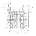
本件では、内燃機関1は、V型に配置されている2つのシリンダ列2、3を、それ自体既知の方法で有する。2つのシリンダ列2、3の各列には、それぞれ、4つのシリンダ2a、2b、2c、2d、および3a、3b、3c、3dがある。もちろん、各シリンダ列2、3は他のシリンダ数であってもよく、同様にシリンダ列の数も他の数であってもよい。
In this case, the internal combustion engine 1 has two
吸気配管4、5は、それぞれ、2つのシリンダ列2、3に通じ、吸気配管に連結する吸入ダクト4a、4b、4c、4d、および5a、5b、5c、5dをそれぞれ通じて、それぞれのシリンダ2a、2b、2c、2dおよび3a、3b、3c、3dに、それぞれ吸気を供給する。燃焼中にシリンダ2a、2b、2c、2dおよび3a、3b、3c、3d内で発生する排気ガスは、排気ガス配管6および7を通して排出され、これらの配管6、7は、それぞれ排気ダクト6a、6b、6c、6dおよび7a、7b、7c、7dを通じて、それぞれシリンダ2a、2b、2c、2dおよび3a、3b、3c、3dに連結される。
The
シリンダ列3のシリンダ3a、3b、3c、3dは、内燃機関1が運転中に停止状態にすることができ、高負荷運転点用に構成されるシリンダである。対照的に、シリンダ列2のシリンダ2a、2b、2c、2dは、低負荷運転点用に構成されるシリンダであり、シリンダ2a、2b、2c、2dも、ある状況下、たとえば、高いが最大ではない負荷要求のある運転時点において停止状態にできるように構成しても良い。このように、シリンダ2a、2b、2c、2dは、排気ガスに関して最適化され、低燃料消費及び低汚染物質排出のために構成されるかまたは最適化される。一方、停止状態にすることができるシリンダ3a、3b、3c、3dは、高負荷に関して最適化され、高出力、または高トルクを出力するために構成される。
The
シリンダ3a、3b、3c、3dを、比較的高い負荷の運転点用に組込むために、前記シリンダは、たとえば、シリンダ2a、2b、2c、2dより低い圧縮比εを有すると良い。そのような低圧縮比εは、たとえば、他のピストンまたはコネクティングロッドを使用することによりもたらすことができるが、内燃機関1が温まっているときに、内燃機関1の窒素酸化物排出量が減少するという状況をもたらす。一方、低負荷運転点用に構成されるシリンダ2a、2b、2c、2dが高い圧縮比εであると、炭化水素および一酸化炭素の排出量が低減されるが、これは、特にコールドスタートモードにおいて、問題を引き起こすことがある。さらに、より低い圧縮比εの結果生じるより低いピーク圧力により、シリンダ3a、3b、3c、3d側により高い負荷を掛けることが可能である。
In order to incorporate the
噴射ノズル8a、8b、8c、8dが、シリンダ2a、2b、2c、2dの吸入ダクト4a、4b、4c、4d内に配置され、前記噴射ノズル8a、8b、8c、8dは、シリンダ3a、3b、3c、3dの吸入ダクト5a、5b、5c、5d内に配置される噴射ノズル9a、9b、9c、9dより低い燃料流量を有する。その結果、シリンダ2a、2b、2c、2dより、シリンダ3a、3b、3c、3dに多くの燃料流量が供給でき、その結果、前記シリンダは、より高いトルクを発生できる。噴射ノズル9a、9b、9c、9dのより高い燃料流量は、たとえば、より大きなノズル孔または噴射器の変更によりもたらすことができる。
The
さらに、本例示的実施形態のシリンダ2a、2b、2c、2dは、シリンダ3a、3b、3c、3dより少ない数、具体的には、各2個の摺動バルブ10a、10b、10c、10dを有し、本件では、シリンダ3a、3b、3c、3dには、それぞれ4個の摺動バルブ11a、11b、11c、11dが設けられる。また、これは、シリンダ2a、2b、2c、2dに比較して、シリンダ3a、3b、3c、3dがより高いパワーを発生することに貢献する。
Furthermore, the
給気は、排気ガスターボチャージャ12によりシリンダ2a、2b、2c、2dに、さらなる排気ガスターボチャージャ13によりシリンダ3a、3b、3c、3dに、それ自体既知の方法で供給される。シリンダ3a、3b、3c、3dのパワーをさらに増加させることができるように、排気ガスターボチャージャ13は、低負荷運転点用に構成されるシリンダ2a、2b、2c、2dの排気ガスターボチャージャ12より高い空気流量を有する。これは、シリンダ3a、3b、3c、3dのより高いパワーによる高回転速度における内燃機関1の比較的高いパワーレベルをもたらす。一方、シリンダ2a、2b、2c、2dによる比較的高いトルクは、排気ガスターボチャージャ12のより低い空気流量による低回転速度においても可能である。さらに、排気ガスターボチャージャ13には、それ自体既知のいわゆるウェイストゲートを装備することもでき、ある状況下では、調節可能なタービン構造を装備することもできる。
The supply air is supplied to the
内燃機関1の汚染物質排出量をできるだけ低く維持するために、シリンダ2a、2b、2c、2dは、それ自体既知の方法で動作可能な排気ガス再循環装置14を装備する。適切である場合は、排気ガス再循環装置14に排気ガス循環冷却器(図示せず)を装備することもできる。
In order to keep the pollutant emissions of the internal combustion engine 1 as low as possible, the
さらに、また、それ自体既知の吸入ダクトを停止状態にする装置15a、15b、15c、15dが、たとえば、バルブなどの形で吸入ダクト4a、4b、4c、4d内に設けられる。また、この対策は、シリンダ2a、2b、2c、2dの排気を減少させるためにも使用されるが、そのような対策は、シリンダ3a、3b、3c、3dには省略でき、また、上記の排気ガス循環装置14も省略できる。
Furthermore,
高負荷運転点用に構成されるシリンダ3a、3b、3c、3dにおける、排気ガスの後処理または混合物の調整に使用される様々な対策の省略の結果として、内燃機関1のコスト削減のかなりの可能性が出てくる。たとえば、これに関連して、シリンダ2a、2b、2c、2dには、シリンダ3a、3b、3c、3dとは異なった排気ガスシステムが使用できる。
As a result of the omission of various measures used for exhaust gas aftertreatment or mixture adjustment in the
内燃機関1は、ディーゼルエンジンとしてまたは火花点火機関として実施でき、電子制御装置(図示せず)により、それぞれのシリンダが確実に静かに作動および停止状態になる。シリンダ2a、2b、2c、2dおよび3a、3b、3c、3dの2グループの熱管理が、それ相応に組込まれている場合は、内燃機関1のより早い加熱をもたらすこともできる。
The internal combustion engine 1 can be implemented as a diesel engine or as a spark ignition engine, and an electronic control unit (not shown) ensures that each cylinder is quietly activated and stopped. If the two groups of thermal management of the
V型の内燃機関1は、特に、汚染物質を削減するための各構成部品の異なる用途の結果として、図示された形が適切であるが、直列型(図示せず)内燃機関1において高負荷運転点用の各シリンダおよび低負荷運転点用のその他のシリンダを組込むことも可能である。 The V-type internal combustion engine 1 is suitable in the illustrated form, particularly as a result of the different uses of the components for reducing pollutants, but the series-type (not shown) internal combustion engine 1 is heavily loaded. It is also possible to incorporate each cylinder for operating points and other cylinders for low load operating points.
さらに、高負荷運転点用に組込まれ、運転中に停止状態にすることのできるシリンダ3a、3b、3c、3dの数を、低負荷運転点用に構成されるシリンダ2a、2b、2c、2dの数と違えることも可能であり、これは、具体的には、シリンダ3a、3b、3c、3dが、高負荷運転点用に構成される結果としてのパワーの増加がどのくらい大きいか、またはどの排気ガス制限値が適合し得るかによって決まる。
Furthermore, the number of
Claims (10)
運転中に停止状態にできる前記シリンダ(3a、3b、3c、3d)が、高負荷運転点用に構成され、残りの前記シリンダ(2a、2b、2c、2d)が、低負荷運転点用に構成されることを特徴とする内燃機関。 In an internal combustion engine having a plurality of cylinders, at least some of which can be stopped during operation,
The cylinders (3a, 3b, 3c, 3d) that can be stopped during operation are configured for high load operating points and the remaining cylinders (2a, 2b, 2c, 2d) are for low load operating points. An internal combustion engine characterized by being configured.
Applications Claiming Priority (2)
| Application Number | Priority Date | Filing Date | Title |
|---|---|---|---|
| DE10204482A DE10204482A1 (en) | 2002-02-05 | 2002-02-05 | Internal combustion engine |
| PCT/EP2002/014453 WO2003067059A1 (en) | 2002-02-05 | 2002-12-18 | Internal combustion engine comprising deactivatable cylinders |
Publications (2)
| Publication Number | Publication Date |
|---|---|
| JP2005517115A true JP2005517115A (en) | 2005-06-09 |
| JP2005517115A5 JP2005517115A5 (en) | 2005-12-22 |
Family
ID=27588340
Family Applications (1)
| Application Number | Title | Priority Date | Filing Date |
|---|---|---|---|
| JP2003566387A Abandoned JP2005517115A (en) | 2002-02-05 | 2002-12-18 | Internal combustion engine having a cylinder that can be stopped |
Country Status (5)
| Country | Link |
|---|---|
| US (1) | US7028678B2 (en) |
| EP (1) | EP1472448A1 (en) |
| JP (1) | JP2005517115A (en) |
| DE (1) | DE10204482A1 (en) |
| WO (1) | WO2003067059A1 (en) |
Cited By (2)
| Publication number | Priority date | Publication date | Assignee | Title |
|---|---|---|---|---|
| JP2013249747A (en) * | 2012-05-30 | 2013-12-12 | Isuzu Motors Ltd | Internal combustion engine |
| JP2015021402A (en) * | 2013-07-17 | 2015-02-02 | 三菱自動車工業株式会社 | Control device for engine |
Families Citing this family (32)
| Publication number | Priority date | Publication date | Assignee | Title |
|---|---|---|---|---|
| US7552583B2 (en) * | 2004-11-08 | 2009-06-30 | Caterpillar Inc. | Exhaust purification with on-board ammonia production |
| DE102004040925A1 (en) * | 2004-08-24 | 2006-03-02 | Robert Bosch Gmbh | Method and device for operating an internal combustion engine having at least two cylinder banks |
| DE102005014789A1 (en) * | 2005-03-31 | 2006-10-05 | Nonox B.V. | Method for controlling the present in the combustion chamber of an internal combustion engine combustible air-fuel mixture |
| US7167792B1 (en) | 2006-01-23 | 2007-01-23 | Ford Global Technologies, Llc | Method for stopping and starting an internal combustion engine having a variable event valvetrain |
| US7240480B1 (en) * | 2006-02-17 | 2007-07-10 | Ford Global Technologies, Llc | Dual Combustion Mode Engine |
| US7621126B2 (en) * | 2006-04-05 | 2009-11-24 | Ford Global Technoloigies, LLC | Method for controlling cylinder air charge for a turbo charged engine having variable event valve actuators |
| US7458346B2 (en) * | 2006-04-05 | 2008-12-02 | Ford Global Technologies, Llc | Method for controlling valves of an engine having a variable event valvetrain during an engine stop |
| US7562530B2 (en) * | 2006-04-05 | 2009-07-21 | Ford Global Technologies, Llc | Method for controlling an internal combustion engine having a variable event valvetrain |
| US8230684B2 (en) * | 2007-04-20 | 2012-07-31 | Borgwarner Inc. | Combustion engine breathing system including a compressor valve for a biturbo with cylinder deactivation |
| US7770393B2 (en) * | 2007-07-13 | 2010-08-10 | Ford Global Technologies, Llc | Control of turbocharger imbalance |
| US8209109B2 (en) * | 2007-07-13 | 2012-06-26 | Ford Global Technologies, Llc | Method for compensating an operating imbalance between different banks of a turbocharged engine |
| CN102713213B (en) * | 2009-12-04 | 2015-01-14 | 丰田自动车株式会社 | Spark ignition type internal combustion engine |
| DE102010047795A1 (en) * | 2010-10-07 | 2012-04-12 | Daimler Ag | Operating method for an internal combustion engine |
| US8631646B2 (en) * | 2011-05-12 | 2014-01-21 | Ford Global Technologies, Llc | Methods and systems for variable displacement engine control |
| DE102011090160B4 (en) * | 2011-12-30 | 2023-02-23 | Dr.Ing.H.C. F. Porsche Ag | Internal combustion engine with an arrangement for routing exhaust gas and charge air |
| EP2657485B1 (en) * | 2012-04-24 | 2015-08-05 | Ford Global Technologies, LLC | Method for operating an externally ignited combustion engine with partial shut-down |
| EP2657487B1 (en) * | 2012-04-24 | 2019-04-03 | Ford Global Technologies, LLC | Self-ignited combustion engine with partial shut-down and method for operating such a combustion engine with optimised emissions |
| EP2657486A1 (en) | 2012-04-24 | 2013-10-30 | Ford Global Technologies, LLC | Self-ignited combustion engine with partial shut-down and method for operating such a combustion engine with optimised consumption |
| EP2657484B1 (en) * | 2012-04-24 | 2015-03-04 | Ford Global Technologies, LLC | Externally ignited combustion engine with partial shut-down and method for operating such a combustion engine |
| DE202015001995U1 (en) | 2014-03-14 | 2015-06-30 | Ferrari S.P.A. | Internal combustion engine with partial cylinder deactivation during operation in the lower load range |
| JP6011576B2 (en) | 2014-04-24 | 2016-10-19 | トヨタ自動車株式会社 | Control device for internal combustion engine |
| GB2528259B (en) * | 2014-07-14 | 2020-06-03 | Ford Global Tech Llc | Selectively deactivatable engine cylinder |
| JP6135693B2 (en) | 2015-02-20 | 2017-05-31 | トヨタ自動車株式会社 | Supercharged engine control device |
| CN106065809B (en) | 2015-04-24 | 2020-12-25 | 福特环球技术公司 | Engine with two-stage supercharging and exhaust gas aftertreatment and method for operating the same |
| DE102015208538B3 (en) * | 2015-05-07 | 2016-10-06 | Ford Global Technologies, Llc | motor vehicle |
| DE102015214616B4 (en) * | 2015-07-31 | 2018-08-23 | Ford Global Technologies, Llc | Method for operating a exhaust-gas-charged internal combustion engine with partial deactivation |
| US10066559B2 (en) * | 2015-10-27 | 2018-09-04 | Ford Global Technologies, Llc | Method and system for engine control |
| AT517716B1 (en) * | 2015-10-28 | 2017-04-15 | Avl List Gmbh | MORE CYLINDER internal combustion engine |
| ITUB20155457A1 (en) * | 2015-11-11 | 2017-05-11 | Fpt Ind Spa | INTERNAL COMBUSTION ENGINE AND METHOD OF CONTROL OF THE SAME ENGINE |
| US11199162B2 (en) | 2016-01-19 | 2021-12-14 | Eaton Intelligent Power Limited | In-cylinder EGR and VVA for aftertreatment temperature control |
| DE102016218544A1 (en) | 2016-09-27 | 2018-03-29 | Bayerische Motoren Werke Aktiengesellschaft | Reciprocating internal combustion engine and method for operating a reciprocating internal combustion engine |
| GB2559186B (en) * | 2017-01-31 | 2020-06-03 | Delphi Automotive Systems Lux | Fuel injector and combustion chamber design for cylinder-on-demand (COD) technology |
Family Cites Families (21)
| Publication number | Priority date | Publication date | Assignee | Title |
|---|---|---|---|---|
| DE2325060A1 (en) * | 1972-05-24 | 1973-12-13 | Saviem | MULTI-CYLINDER DIESEL ENGINE |
| FR2252762A5 (en) * | 1973-11-28 | 1975-06-20 | Saviem | |
| JPS5569736A (en) * | 1978-11-17 | 1980-05-26 | Nissan Motor Co Ltd | Multi-cylinder internal combustion engine |
| JPS5591754A (en) * | 1978-12-28 | 1980-07-11 | Nissan Motor Co Ltd | Exhaust reflux device under controlling working cylinder number |
| JPS5853178B2 (en) * | 1979-12-12 | 1983-11-28 | 日産自動車株式会社 | cylinder number control engine |
| JPS56118532A (en) * | 1980-02-22 | 1981-09-17 | Nissan Motor Co Ltd | Cylinder number controllable engine |
| JPS57186036A (en) * | 1981-05-13 | 1982-11-16 | Nissan Motor Co Ltd | Cylinder quantity controlled engine |
| US4411230A (en) * | 1981-06-17 | 1983-10-25 | Lee John K | Master cylinder internal combustion engine |
| IT1149700B (en) * | 1982-02-26 | 1986-12-03 | Alfa Romeo Auto Spa | MODULAR TYPE MULTI-CYLINDER ENGINE |
| JPS59200037A (en) * | 1983-04-26 | 1984-11-13 | Daihatsu Motor Co Ltd | Multicylinder internal-combustion engine |
| US4473044A (en) * | 1984-01-09 | 1984-09-25 | Kenneth Hudson | Mileage improvement system for internal combustion engines |
| JPS61192822A (en) * | 1985-02-21 | 1986-08-27 | Toyota Motor Corp | Variable cylinder number type internal-combustion engine equipped with supercharger |
| DE3631284C1 (en) * | 1986-09-13 | 1987-04-16 | Mtu Friedrichshafen Gmbh | Multi-cylinder diesel internal combustion engine with a low compression ratio in the cylinders |
| JPH03275949A (en) * | 1990-03-23 | 1991-12-06 | Mazda Motor Corp | Diesel engine |
| US5826563A (en) * | 1997-07-28 | 1998-10-27 | General Electric Company | Diesel engine cylinder skip firing system |
| DE19812090C2 (en) | 1998-03-19 | 2000-03-09 | Daimler Chrysler Ag | Multi-cylinder piston internal combustion engine with at least two cylinder banks |
| DE19831251C2 (en) * | 1998-07-11 | 2000-04-27 | Daimler Chrysler Ag | Rechargeable internal combustion engine with cylinder deactivation |
| US6318310B1 (en) * | 1999-08-05 | 2001-11-20 | Caterpillar Inc. | Internal combustion engine |
| BE1013791A5 (en) * | 2000-10-26 | 2002-08-06 | Gerhard Schmitz | FIVE-TIME INTERNAL COMBUSTION ENGINE. |
| US6640543B1 (en) * | 2001-09-21 | 2003-11-04 | Western Washington University | Internal combustion engine having variable displacement |
| US6786190B2 (en) * | 2002-11-25 | 2004-09-07 | General Motors Corporation | Compact turbocharged cylinder deactivation engine |
-
2002
- 2002-02-05 DE DE10204482A patent/DE10204482A1/en not_active Withdrawn
- 2002-12-18 JP JP2003566387A patent/JP2005517115A/en not_active Abandoned
- 2002-12-18 EP EP02796670A patent/EP1472448A1/en not_active Withdrawn
- 2002-12-18 WO PCT/EP2002/014453 patent/WO2003067059A1/en not_active Application Discontinuation
-
2004
- 2004-08-05 US US10/911,906 patent/US7028678B2/en not_active Expired - Fee Related
Cited By (2)
| Publication number | Priority date | Publication date | Assignee | Title |
|---|---|---|---|---|
| JP2013249747A (en) * | 2012-05-30 | 2013-12-12 | Isuzu Motors Ltd | Internal combustion engine |
| JP2015021402A (en) * | 2013-07-17 | 2015-02-02 | 三菱自動車工業株式会社 | Control device for engine |
Also Published As
| Publication number | Publication date |
|---|---|
| US20050034701A1 (en) | 2005-02-17 |
| US7028678B2 (en) | 2006-04-18 |
| DE10204482A1 (en) | 2003-08-14 |
| EP1472448A1 (en) | 2004-11-03 |
| WO2003067059A1 (en) | 2003-08-14 |
Similar Documents
| Publication | Publication Date | Title |
|---|---|---|
| JP2005517115A (en) | Internal combustion engine having a cylinder that can be stopped | |
| JP4161974B2 (en) | Control device for diesel internal combustion engine | |
| EP1710423A1 (en) | Exhaust gas purifying apparatus for internal combustion engine | |
| US20130019593A1 (en) | Secondary air injection system and method | |
| WO2009050534A1 (en) | An engine unit with dedicated compressor, heating device and turbine on the intake air circuit and automotive vehicle incorporating such engine unit | |
| US20060053786A1 (en) | Control device for supercharged engine | |
| CN114930007B (en) | Exhaust gas recirculation control in dynamic skip fire engines | |
| JP5093407B2 (en) | Combustion control device for internal combustion engine | |
| JP2002317640A (en) | Supercharged gas engine | |
| JP2007162481A (en) | Internal combustion engine with supercharger | |
| JP4803056B2 (en) | Premixed compression ignition internal combustion engine | |
| JP4858647B2 (en) | Fuel injection pressure control device for internal combustion engine | |
| JP2004124744A (en) | Turbocharged engine | |
| JP2008121494A (en) | Controller of internal combustion engine | |
| JP2005201074A (en) | Controller of internal combustion engine | |
| JP2003113730A (en) | INTERNAL COMBUSTION ENGINE WITH NOx STORAGE CATALYST, AND COMBUSTION CONTROL METHOD FOR THE SAME | |
| JP2001159311A (en) | Exhaust emission control device for engine | |
| JP2013119838A (en) | Exhaust gas recirculating device of multicylinder internal combustion engine with turbocharger | |
| JP3344334B2 (en) | Internal combustion engine | |
| JP2004132318A (en) | Exhaust emission control device for internal combustion engine | |
| JP3684968B2 (en) | Fuel injection device for internal combustion engine | |
| JP4305194B2 (en) | Exhaust air-fuel ratio control device for internal combustion engine | |
| JP4325517B2 (en) | Fuel injection control method for internal combustion engine | |
| JP2003293750A (en) | Exhaust emission control device for multicylinder internal combustion engine | |
| JP5083156B2 (en) | Control device for variable cylinder internal combustion engine |
Legal Events
| Date | Code | Title | Description |
|---|---|---|---|
| A762 | Written abandonment of application |
Free format text: JAPANESE INTERMEDIATE CODE: A762 Effective date: 20060823 |